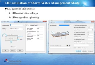
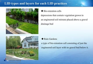
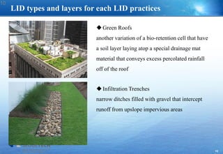
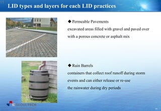
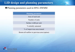
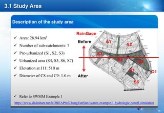
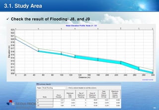
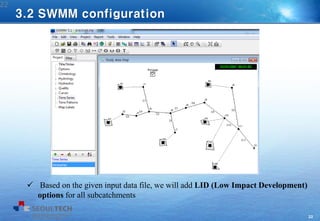
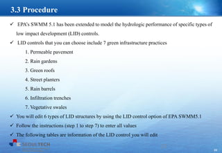
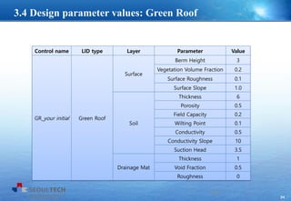
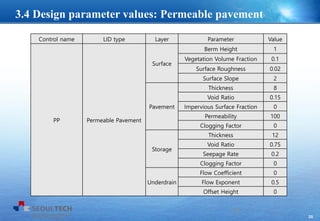
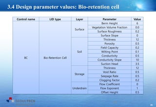
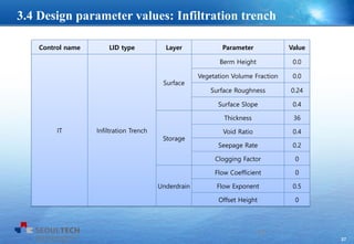
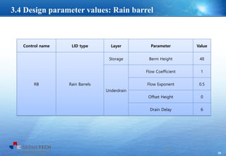
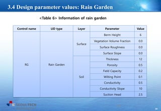
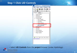
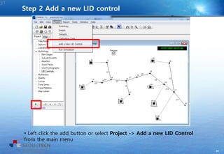
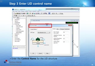
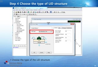
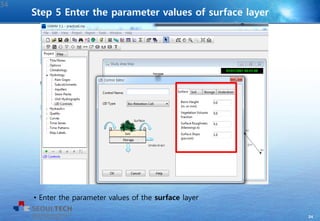
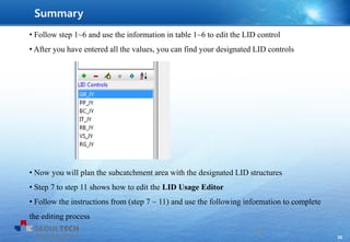
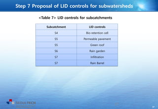
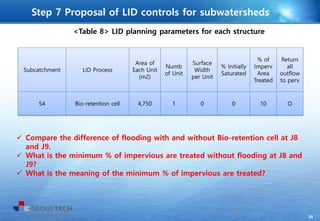
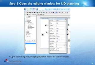
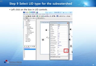
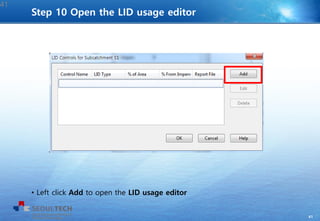
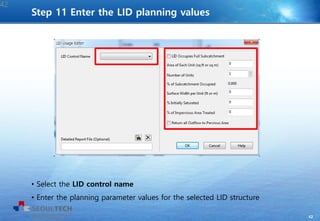
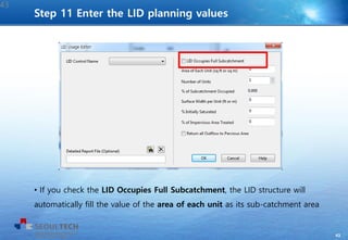
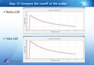
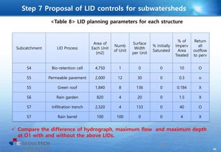
3. 2
1. Introduction
Floods and Droughts
Imperviousness in urban areas are increasing due to climate change and urbanization
Flood, drought, water quality problems are occurring and urged to be managed
2
4. 3
1. Introduction
With the late experience of flood in China, Sponge City became a great issue
< Flood in China, 2010 >
< Concept of Sponge City >
Flood and Sponge City
3
5. 4
1. Introduction
Water Sensitive Cities (WSC), a land planning and engineering design approach which
integrates the urban water cycle started in Australia
< Concept of Water Sensitive City >
Water Sensitive Cities (WSC)
4
6. 5
1. Introduction
Low Impact Development (LID)
Low Impact Development (LID) (Prince George’s County, 1999)
Best Management Planning (BMP), Green Infrastructure (GI)
Maintain and capture stormwater to reduce negative effects on receiving water
LID can be a method to mitigate water related problems
LID concepts can be used as basic principles for the achievement of Sponge
Cities and Water Sensitive Cities
Several hydrological models that can simulate the performance of LIDs
5
8. 7
SWMM (Storm Water Management Model)
Developed by EPA (Environmental Protection Agency), US
Dynamic rainfall-runoff simulation model, used for simulation of runoff and qua
lity from urban areas
Used in thousands of sewer and stormwater studies throughout the world
Recently extended to model the hydrologic performance of specific types of LID
controls
Eight types of LIDs: bio-retention cells, rain gardens, green roofs, rain barrels,
infiltration trenches, permeable pavements,
rooftop disconnections, vegetative swales
Storm Water Management Model
7
9. 8
LID editors in EPA SWMM
LID control editor - design
LID usage editor - planning
LID simulation of Storm Water Management Model
8
10. 9
LID types and layers for each LID practices
Bio-retention cells
depressions that contain vegetation grown in
an engineered soil mixture placed above a gravel
drainage bed
Rain Gardens
a type of bio-retention cell consisting of just the
engineered soil layer with no gravel bed below it.
9
11. 10
LID types and layers for each LID practices
Green Roofs
another variation of a bio-retention cell that have
a soil layer laying atop a special drainage mat
material that conveys excess percolated rainfall
off of the roof
Infiltration Trenches
narrow ditches filled with gravel that intercept
runoff from upslope impervious areas
10
12. 11
LID types and layers for each LID practices
Permeable Pavements
excavated areas filled with gravel and paved over
with a porous concrete or asphalt mix
Rain Barrels
containers that collect roof runoff during storm
events and can either release or re-use
the rainwater during dry periods
11
13. 12
LID types and layers for each LID practices
Vegetative Swales
channels or depressed areas with sloping sides
covered with grass and other vegetation
Rooftop Disconnection
downspouts discharge to pervious landscaped areas
and lawns instead of directly into storm drains
12
14. 13
LID types and layers for each LID practices in SWMM
Layers used to model different types of LID units (Rossman, 2010)
(X: required, O: optional)
Performance of the water move by divided layers
13
15. 14
Representation of the water pathway in LIDs of SWMM
Representation of the water pathway in LIDs of SWMM (Rossman, 2010)
14
16. 15
Layer Parameter
Storage Height
Void ratio
Seepage rate
Clogging factor
Drain Flow coefficient
Flow exponent
Offset height
Drain delay
Drainage
mat
Thickness
Void fraction
Roughness
LID design and planning parameters
Layer Design parameter
Surface Storage depth
Vegetative volume fraction
Surface roughness
Surface slope
Swale side slope
Pavement Thickness
Void ratio
Impervious surface fraction
Permeability
Clogging factor
Soil Thickness
Porosity
Field capacity
Wilting point
Conductivity
Conductivity slope
Suction head
Design parameters used in EPA’s SWMM
15
17. 16
LID design and planning parameters
Planning parameter
Area of each unit
Number of units
Surface width per unit
% initially saturated
% of impervious area treated
Return all outflow to pervious area (option)
Planning parameters used in EPA’s SWMM
16
23. 22
Based on the given input data file, we will add LID (Low Impact Development)
options for all subcatchments
22
3.2 SWMM configuration
24. 23
EPA’s SWMM 5.1 has been extended to model the hydrologic performance of specific types of
low impact development (LID) controls.
LID controls that you can choose include 7 green infrastructure practices
1. Permeable pavement
2. Rain gardens
3. Green roofs
4. Street planters
5. Rain barrels
6. Infiltration trenches
7. Vegetative swales
You will edit 6 types of LID structures by using the LID control option of EPA SWMM5.1
Follow the instructions (step 1 to step 7) to enter all values
The following tables are information of the LID control you will edit
23
3.3 Procedure
25. 24
Control name LID type Layer Parameter Value
GR_your initial Green Roof
Surface
Berm Height 3
Vegetation Volume Fraction 0.2
Surface Roughness 0.1
Surface Slope 1.0
Soil
Thickness 6
Porosity 0.5
Field Capacity 0.2
Wilting Point 0.1
Conductivity 0.5
Conductivity Slope 10
Suction Head 3.5
Drainage Mat
Thickness 1
Void Fraction 0.5
Roughness 0
24
3.4 Design parameter values: Green Roof
26. 25
Control name LID type Layer Parameter Value
PP Permeable Pavement
Surface
Berm Height 1
Vegetation Volume Fraction 0.1
Surface Roughness 0.02
Surface Slope 2
Pavement
Thickness 8
Void Ratio 0.15
Impervious Surface Fraction 0
Permeability 100
Clogging Factor 0
Storage
Thickness 12
Void Ratio 0.75
Seepage Rate 0.2
Clogging Factor 0
Underdrain
Flow Coefficient 0
Flow Exponent 0.5
Offset Height 0
25
3.4 Design parameter values: Permeable pavement
27. 26
Control name LID type Layer Parameter Value
BC Bio-Retention Cell
Surface
Berm Height 6
Vegetation Volume Fraction 0.0
Surface Roughness 0.2
Surface Slope 0
Soil
Thickness 12
Porosity 0.5
Field Capacity 0.2
Wilting Point 0.1
Conductivity 0.5
Conductivity Slope 10
Suction Head 3.5
Storage
Thickness 12
Void Ratio 0.5
Seepage Rate 0.5
Clogging Factor 0.2
Underdrain
Flow Coefficient 0
Flow Exponent 1
Offset Height 0.5
26
3.4 Design parameter values: Bio-retention cell
28. 27
Control name LID type Layer Parameter Value
IT Infiltration Trench
Surface
Berm Height 0.0
Vegetation Volume Fraction 0.0
Surface Roughness 0.24
Surface Slope 0.4
Storage
Thickness 36
Void Ratio 0.4
Seepage Rate 0.2
Clogging Factor 0
Underdrain
Flow Coefficient 0
Flow Exponent 0.5
Offset Height 0
27
3.4 Design parameter values: Infiltration trench
29. 28
Control name LID type Layer Parameter Value
RB Rain Barrels
Storage Berm Height 48
Underdrain
Flow Coefficient 1
Flow Exponent 0.5
Offset Height 0
Drain Delay 6
28
3.4 Design parameter values: Rain barrel
30. 29
<Table 6> Information of rain garden
Control name LID type Layer Parameter Value
RG Rain Garden
Surface
Berm Height 6
Vegetation Volume Fraction 0.0
Surface Roughness 0.0
Surface Slope 0.0
Soil
Thickness 12
Porosity 0.5
Field Capacity 0.2
Wilting Point 0.1
Conductivity 0.5
Conductivity Slope 10
Suction Head 2.5
29
3.4 Design parameter values: Rain Garden
31. 30
• Select LID Controls from the project browser (under Hydrology)
Step 1 Click LID Controls
30
32. 31
• Left click the add button or select Project -> Add a new LID Control
from the main menu
Step 2 Add a new LID control
31
33. 32
• Enter the Control Name for the LID structure
Step 3 Enter LID control name
32
34. 33
• Choose the type of the LID structure
Step 4 Choose the type of LID structure
33
35. 34
• Enter the parameter values of the surface layer
Step 5 Enter the parameter values of surface layer
34
36. 35
• To enter the parameter values of the Soil, Storage, and Underdrain layer
click the tab of the layer
Step 6 Enter the parameter values of the Soil, Storage and underdrain
35
37. 36
• Follow step 1~6 and use the information in table 1~6 to edit the LID control
• After you have entered all the values, you can find your designated LID controls
• Now you will plan the subcatchment area with the designated LID structures
• Step 7 to step 11 shows how to edit the LID Usage Editor
• Follow the instructions from (step 7 ~ 11) and use the following information to complete
the editing process
36
Summary
38. 37
Subcatchment LID controls
S4 Bio-retention cell
S5 Permeable pavement
S5 Green roof
S6 Rain garden
S7 Infiltration
S7 Rain Barrel
<Table 7> LID controls for subcatchments
37
Step 7 Proposal of LID controls for subwatersheds
39. 38
Subcatchment LID Process
Area of
Each Unit
(m2)
Numb
of Unit
Surface
Width
per Unit
% Initially
Saturated
% of
Imperv
Area
Treated
Return
all
outflow
to perv
S4 Bio-retention cell 4,750 1 0 0 10 O
<Table 8> LID planning parameters for each structure
38
Step 7 Proposal of LID controls for subwatersheds
Compare the difference of flooding with and without Bio-retention cell at J8
and J9.
What is the minimum % of impervious are treated without flooding at J8 and
J9?
What is the meaning of the minimum % of impervious are treated?
40. 39
• Open the editing window (properties) of one of the subcatchments
Step 8 Open the editing window for LID planning
39
41. 40
• Left click on the box in LID controls
Step 9 Select LID type for the subwatershed
40
42. 41
• Left click Add to open the LID usage editor
41
Step 10 Open the LID usage editor
43. 42
• Select the LID control name
• Enter the planning parameter values for the selected LID structure
42
Step 11 Enter the LID planning values
44. 43
• If you check the LID Occupies Full Subcatchment, the LID structure will
automatically fill the value of the area of each unit as its sub-catchment area
43
Step 11 Enter the LID planning values
46. 45
Subcatchment LID Process
Area of
Each Unit
(m2)
Numb
of Unit
Surface
Width
per Unit
% Initially
Saturated
% of
Imperv
Area
Treated
Return
all
outflow
to perv
S4 Bio-retention cell 4,750 1 0 0 10 O
S5 Permeable pavement 2,000 12 30 0 0.3 o
S5 Green roof 1,840 8 136 0 0.184 X
S6 Rain garden 820 4 20 0 1.5 X
S7 Infiltration trench 2,320 4 133 0 40 O
S7 Rain barrel 100 100 0 0 4 X
<Table 8> LID planning parameters for each structure
45
Step 7 Proposal of LID controls for subwatersheds
Compare the difference of hydrograph, maximum flow and maximum depth
at O1 with and without the above LIDs.
47. 46
Summarize all comparative results for your previous simulations.
You had found the conduit sizes of C8 and C9 with no flooding at J8 and
J9 (1.1 m and 1.2 m). You can resize the conduit considering 20% safety
margin. Can you present the main function of LID plan through this
example.
Describe your planning specification of Bio-retention cell for S4 without
flooding at J8 and J9.
Describe the general benefits of LID practices. You can use various
websites and documents.
Additional Exercise
46