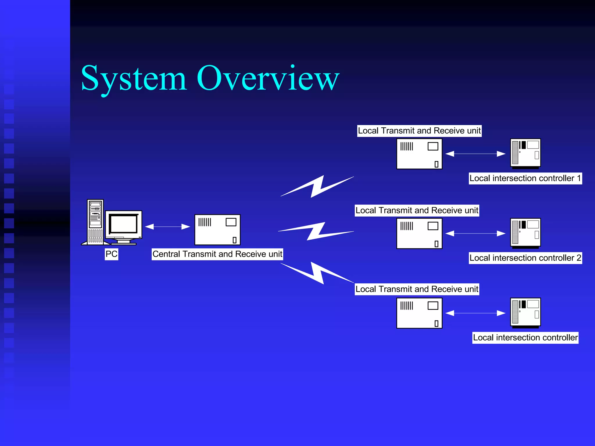
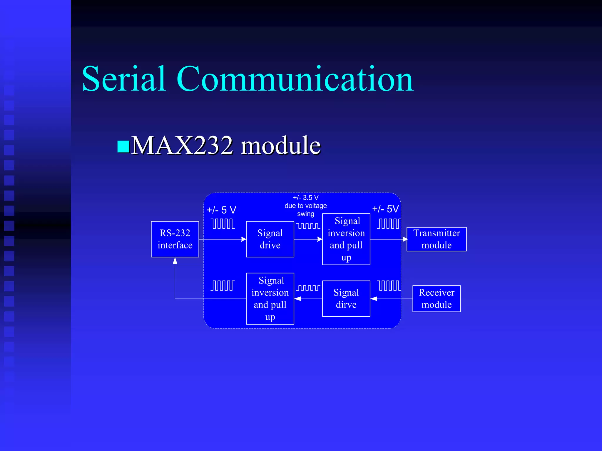
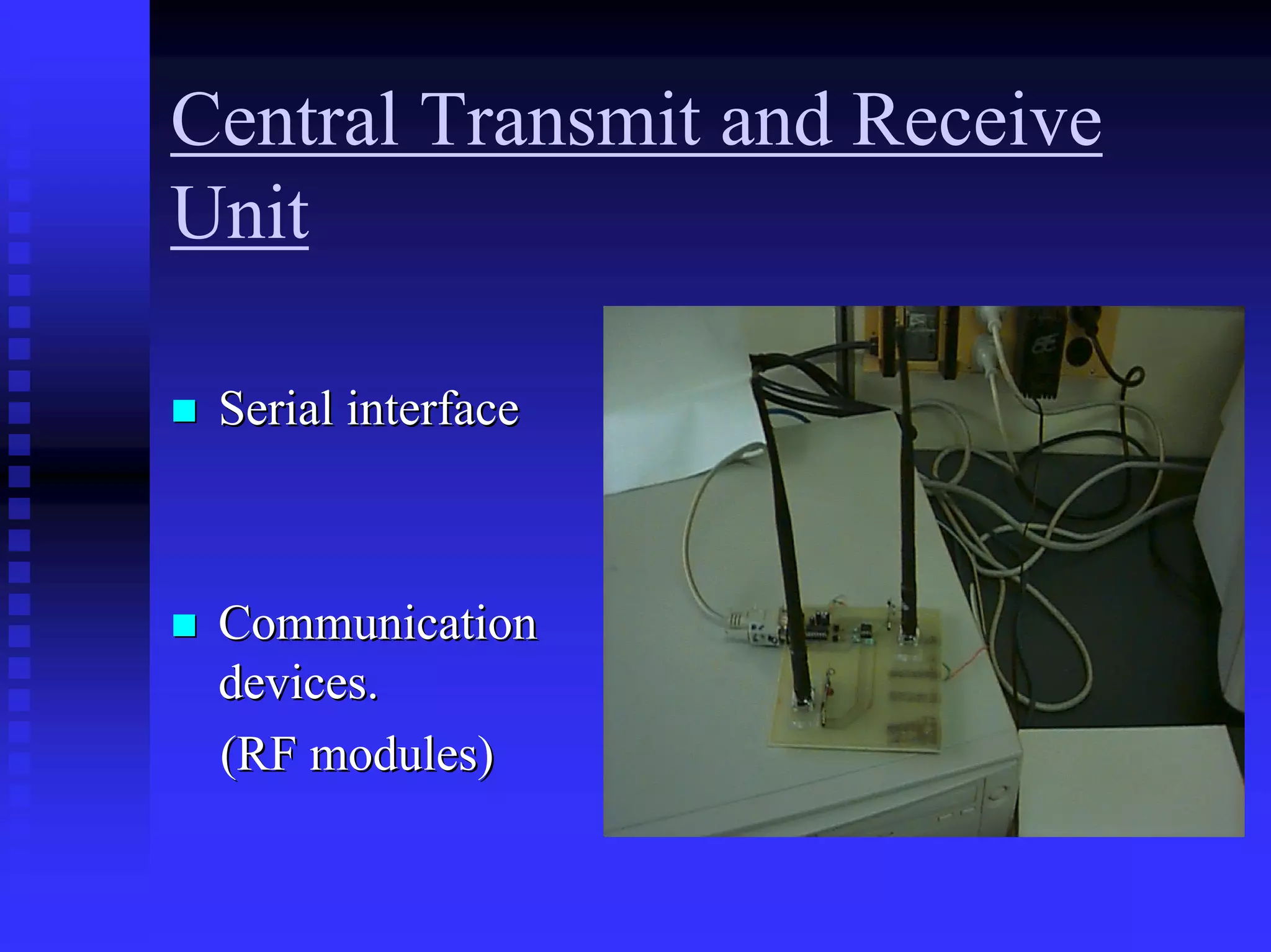
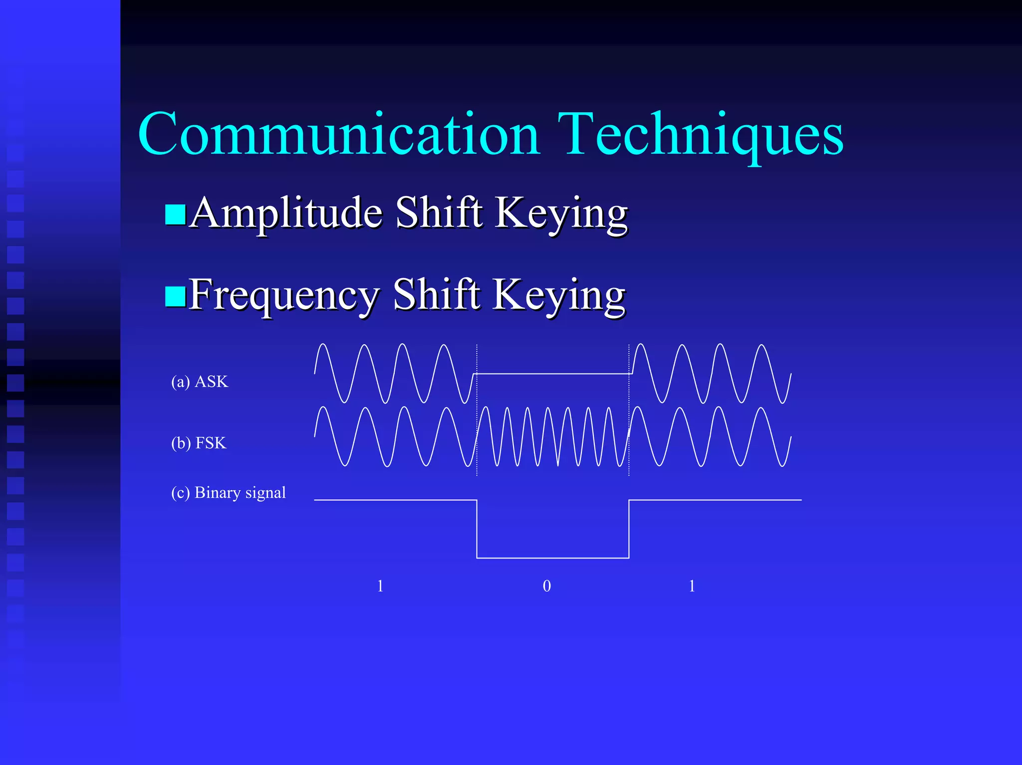
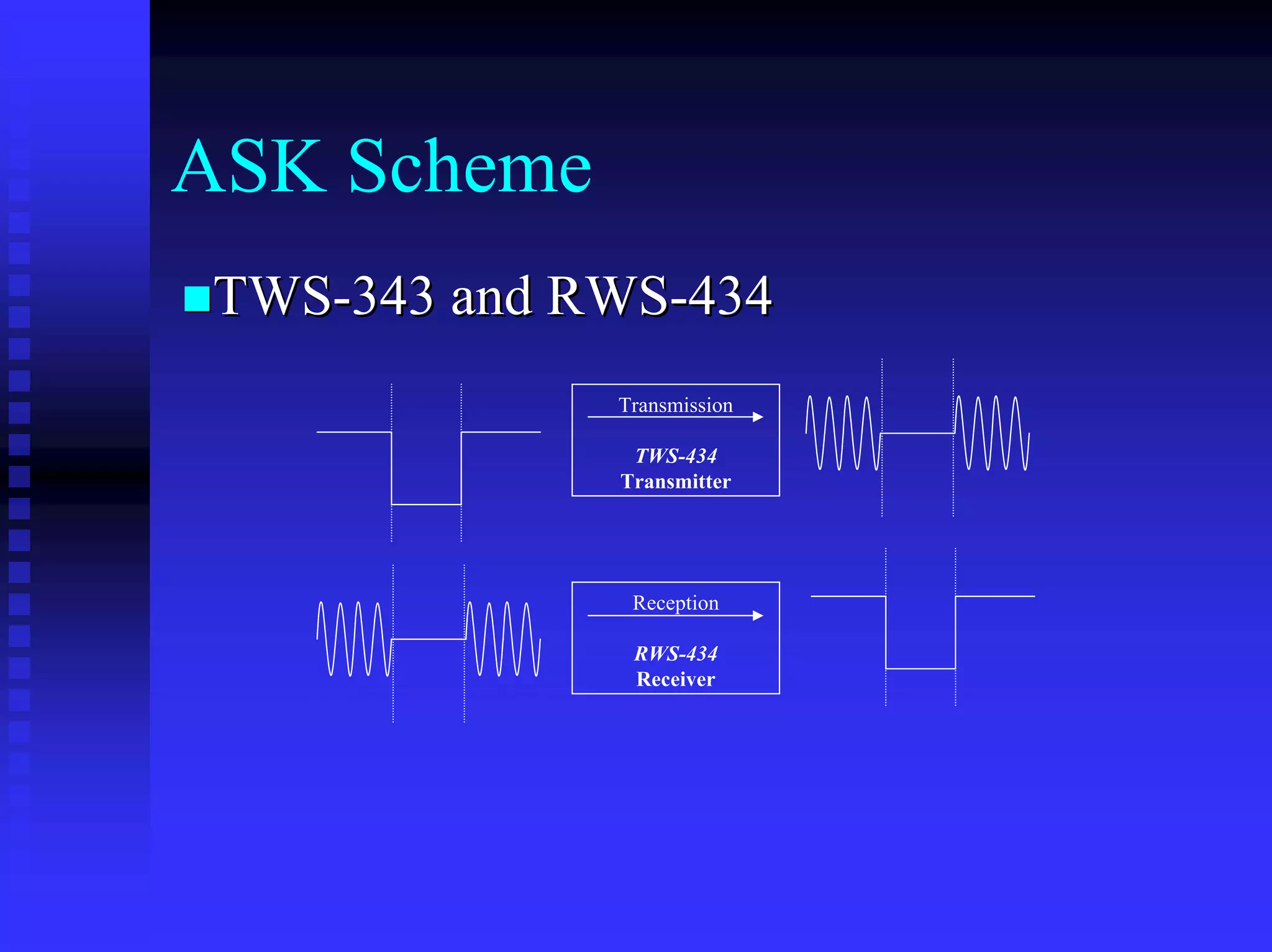
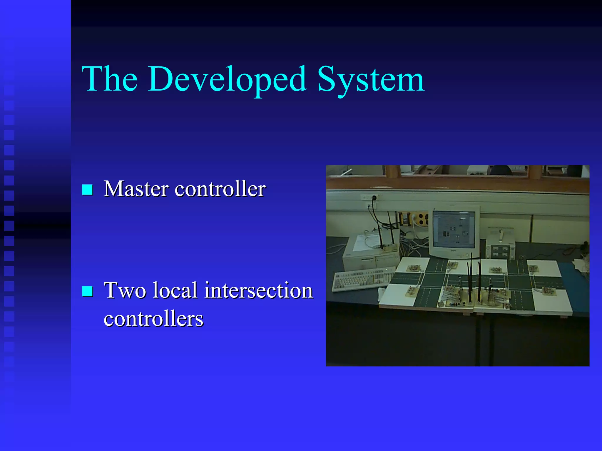
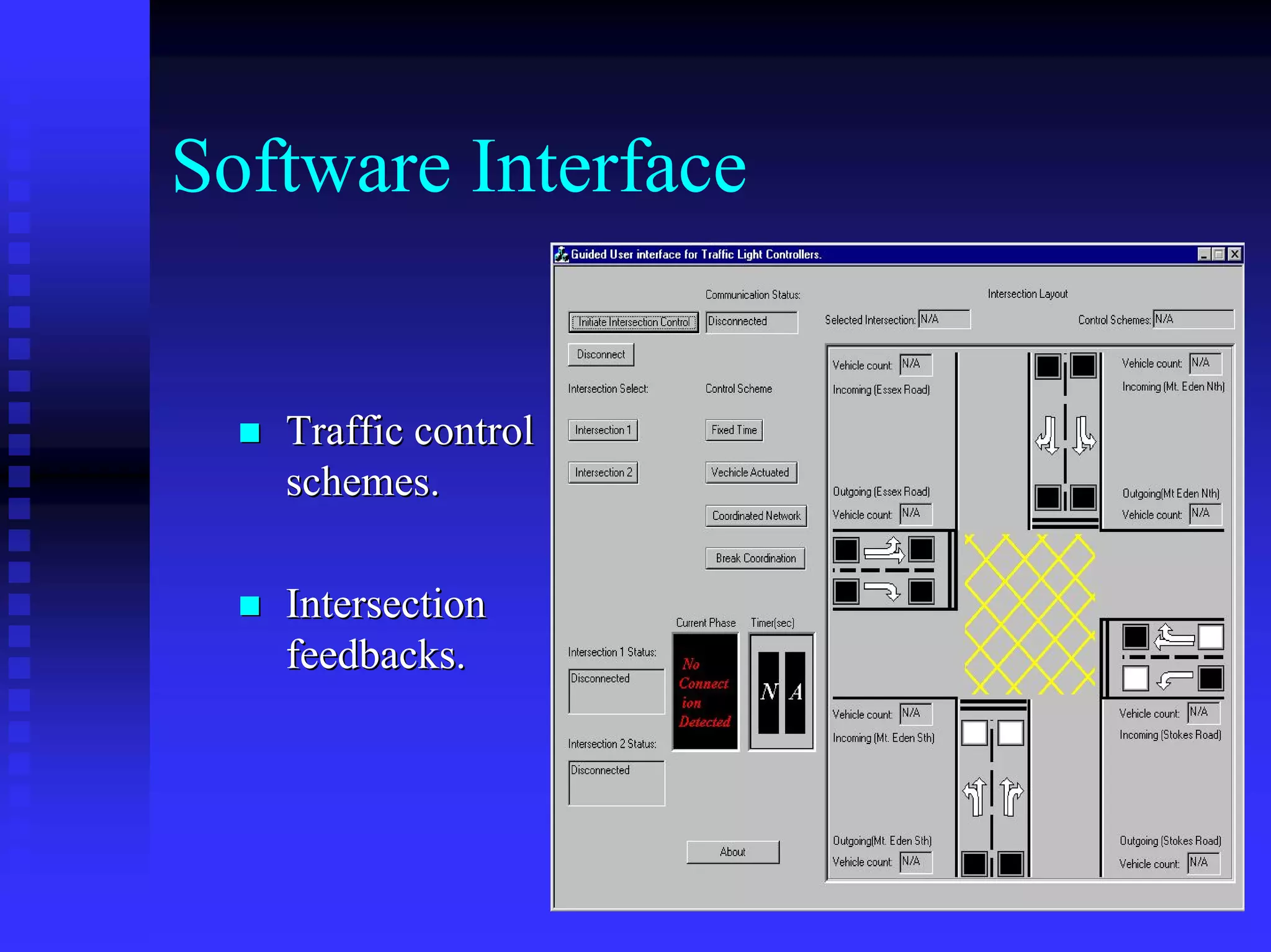
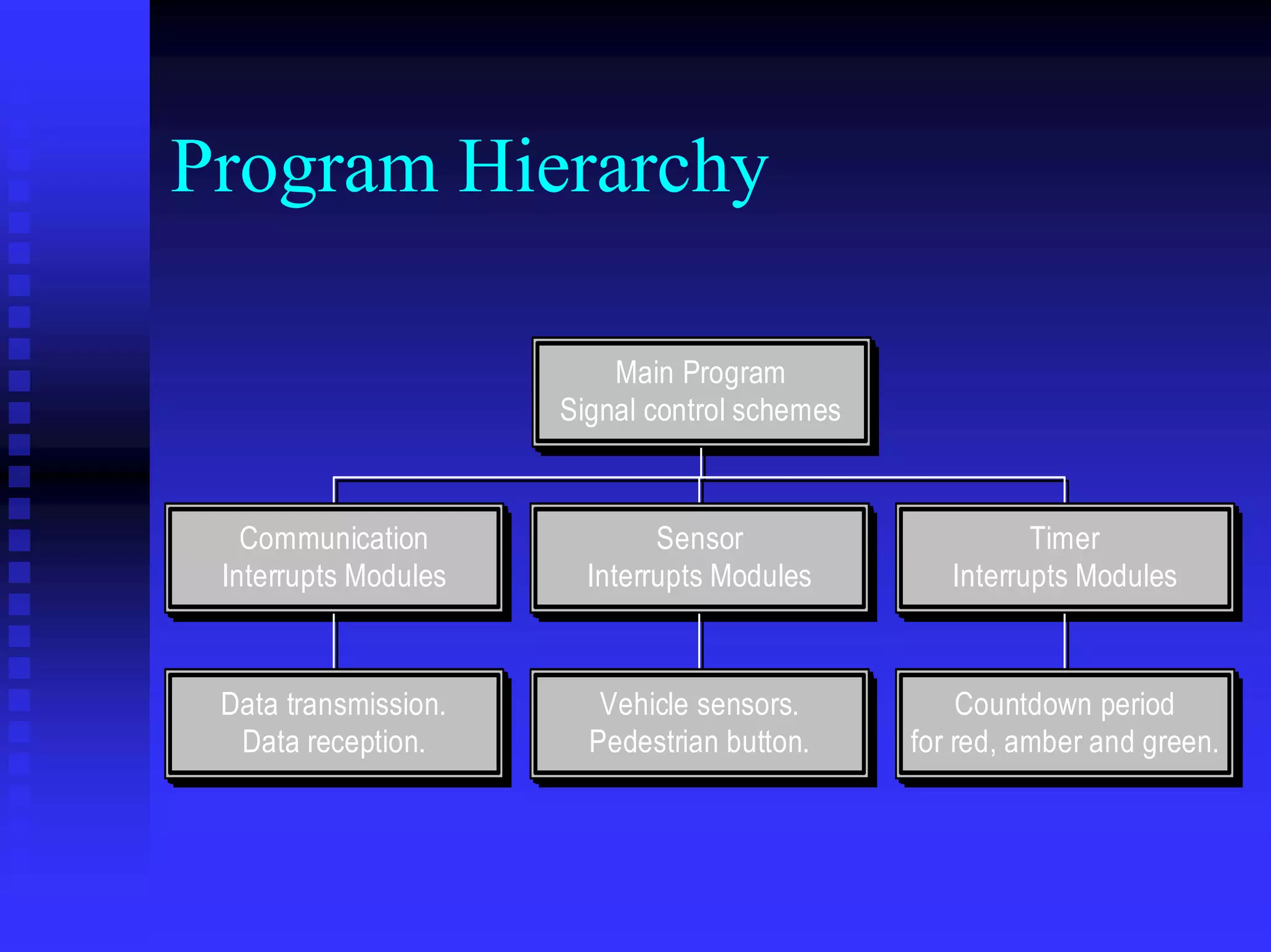
Traffic Light Controller

      Department of Electrical &
       Electronic Engineering

Tiong Bing                          Yuhao Huang

Supervisor: Dr. Waleed H. Abdulla
Project Goals

 Design an independent traffic light controller.

 Implement network coordination

 Design of central controller
System Overview
                                          Local Transmit and Receive unit


                                                                      Local intersection controller 1


                                          Local Transmit and Receive unit


 PC   Central Transmit and Receive unit                               Local intersection controller 2


                                          Local Transmit and Receive unit


                                                                       Local intersection controller
Traffic Control Schemes

 Pre-Timed

 Vehicle Actuated

 Coordinated Network
Serial Communication
   MAX232 module
                                      +/- 3.5 V
                                    due to voltage
                +/- 5 V                 swing
                                                                 +/- 5V
                                                       Signal
     RS-232                Signal                    inversion            Transmitter
    interface              drive                      and pull              module
                                                        up

                            Signal
                          inversion                   Signal               Receiver
                           and pull                   dirve                module
                             up
Central Transmit and Receive
Unit

 Serial interface


 Communication
 devices.
 (RF modules)
Communication Techniques
   Amplitude Shift Keying
   Frequency Shift Keying
 (a) ASK


 (b) FSK

 (c) Binary signal


                     1   0   1
ASK Scheme
 TWS-343 and RWS-434
              Transmission

               TWS-434
              Transmitter


               Reception

               RWS-434
               Receiver
Micro-processor M16
 87 I/O ports

 5 UART channels for serial communication

 Technical support
Case Study
Phase Diagram
                                       INTERSECTION LAYOUT
                                                                                                       N          Phase Group        A           B            C           D
                                                                      5
                                       MT. EDEN                                                                   1                  OFF         GAN          OFF         OFF
                                                                                                                  2                  R           R            GAR         R
                                                                      6
                                                                                      3       7
                                                                                                                  3                  GAR         R            R           R
                                                          8                                                       4                  R           R            GAR         R
  ESSEX
           ROAD                4
                                                                                                  STOKES ROAD
                                                                                                                  5                  SGGA        SGAR         R           R
                                                                                                                  6                  SOFF        GAR          R           R
 3


                   4


                                                                                                                  7                  SGAR        OFF          OFF         OFF
                                                                                      8
                                   8
                                                                                                                  8                  R/OFF       R/OFF        R/OFF       GR
                                                                                              8


                                                                                                           7
                                                                  8                           2
                                                                                                                A preceding S means some form of special control of signal group.
                               5       6
                                                      2                                       1
                                                                                  Control Box
                                                                                                                GAR – Green Amber Red               GAN – Green Amber Off
                                                                                                                R – Red                             R/OFF – Red or Off
                                                      1

                                                      Layout Info:
                                                                                                                Start Phase : A
                       2                                          5       6
                                                                                                                Phase sequences: BACD
Phase Groups:
                                                      4                                       Pedestrian
                                                                                                  8
                       1
                                                                                  3       7

Vehicle Sensors:           1                      2           3               4
                           5                      6           7               8
The Developed System

 Master controller


 Two local intersection
 controllers
Software Interface


   Traffic control
   schemes.

   Intersection
   feedbacks.
Communication Protocol
Between GUI – Local Controllers
 Error control (maintain data integrity)


 Access control (eliminates data collision)
Protocol Basics
 Error Control : Checking digits on data
 packet.

   Parity bit & block sum check : Can only
   detect single bit errors.

   CRC : Cyclic Redundancy check, capable
   of detecting burst errors.
Protocol Basics (continue..)
 Access Control : Allocate link usage to the
 communicating parties.

   Token access control : Circulate data
   transmission token to eliminate data
   collisions
Token passing: operation
principles

   Token
    Data                                     Data
Transmission                             Transmission
Equipment A                              Equipment B

DTE A wishes to send a data to the DTE B, it must first
wait for the receipt of the control token.
Token passing: operation
principles

   Token                Token
    Data                                     Data
                   Token passed
Transmission                             Transmission
                   with data-frame
Equipment A                              Equipment B

On receipt of the token, DTE A initiated transmission of
the frame and then passes the token to DTE B.
Token passing: operation
principles

                                            Token
    Data                                    Data
Transmission                            Transmission
Equipment A                             Equipment B

DTE B has the token and therefore able to reply to DTE
A.
Token passing: operation
principles

                        Token                 Token
    Data                                     Data
                   Token passed
Transmission                             Transmission
                   back to DTE A
Equipment A                              Equipment B

On receipt of the token, DTE B initiated transmission of
the frame and then passes the token to DTE A.
Token passing: operation
principles

   Token
    Data                                    Data
Transmission                            Transmission
Equipment A                             Equipment B

The process repeats itself whenever a data frame is
successfully passed between the two communicating
parties.
GUI-Local Controllers Protocol
 Idle RQ ( idle repeat request )
    Wait for acknowledgements from last
    transmissions before sending another
    frame.

 Token access control
   Enforce one party transmission rule.
Protocols Data Format
      Sender                           Sender                       Sender


     End of                           End of                       End of
     message                          message                      message

   Error control                    Error control                Error control
     message                          message                      message

    Action/Data                         ACK                          NAK
     Receiver       Frame_size        Receiver       Data_Flow     Receiver
   identification                   identification               identification
      number                           number                       number

      Sender                           Sender                       Sender
      address                          address                      address

     Start of                         Start of                     Start of
     message                          message                      message


     Receiver                         Receiver                     Receiver

                                 b) acknowledgement              c) negative
a) Data frame
                                        frame               acknowledgement frame
The Local Controller

 Local transmit and receive
 unit,

 I/O ports and,

 MCU (micro-controller.
MCU software implementation

 Recognizing control commands.

 Manages control of traffic signal.

 Reporting intersection status.
Program Hierarchy

                          Main Program
                          Main Program
                      Signal control schemes
                      Signal control schemes


   Communication
   Communication              Sensor
                               Sensor                    Timer
                                                         Timer
 Interrupts Modules
 Interrupts Modules     Interrupts Modules
                        Interrupts Modules        Interrupts Modules
                                                  Interrupts Modules


 Data transmission.
 Data transmission.      Vehicle sensors.
                         Vehicle sensors.          Countdown period
                                                    Countdown period
  Data reception.
  Data reception.       Pedestrian button.
                        Pedestrian button.     for red, amber and green.
                                               for red, amber and green.
Signal Control Method
                                Starts control                                                      Phase Begin


                        d                            Pha                          Phase Terminate                 Gre
                     ire                                 se T                                                         en
                   xp                                         ime                                      Group               Tim
                 eE                        Phase B                  Exp                                Signal
                                                                                                                              e   Exp
            im                                                          ir   ed                                                       i   red
         eT                                                                                            Green
       as
  Ph
                                eque red
                                    sted


                                                                                          red
                                    pi
                     Walk Time Ex


                                                                                      Expi
                                                                                                                                   Group
                         No t R


 Phase D                                                                                                                           Signal


                                                                                    Time
                                                                    Phase A
pedestrian                                                                                                                         Amber
                         e
                     Phas


                                                                                   Red
  Ph
     as                                                                                                                                  d
  Wa e Ti                                                                                              Group                          ire
                                                                          ed                                                        xp
      lk R me                                                         xpir                                                        eE
          eq Exp                           Phase C                  eE                                 Signal
            ue                                             e Ti
                                                               m                                                              Ti m
              ste ired                                Ph as                                             Red          b   er
                 d                                                                                                Am
Testing of the system

 Communication range 45cm, with the miniature
 model intersection.

 Reliable data communication between the local
 controllers and the GUI master modules.
Limitations
 Operating range and, (1-3 meters with line
 of sight)

 Speed of the communication devices. (3000
 bits per second or 300 bytes per seconds)
Future Improvements
 Network class protocols.

 Better data transmission devices.

 Sophisticated software interface for the
 local controllers.
Conclusions
 An independent Traffic light controller
 based on the case study.

 Final traffic control system is fully
 operational.

 Main project objectives are achieved.

Traffic light controller

  • 1.
    Traffic Light Controller Department of Electrical & Electronic Engineering Tiong Bing Yuhao Huang Supervisor: Dr. Waleed H. Abdulla
  • 2.
    Project Goals Designan independent traffic light controller. Implement network coordination Design of central controller
  • 3.
    System Overview Local Transmit and Receive unit Local intersection controller 1 Local Transmit and Receive unit PC Central Transmit and Receive unit Local intersection controller 2 Local Transmit and Receive unit Local intersection controller
  • 4.
    Traffic Control Schemes Pre-Timed Vehicle Actuated Coordinated Network
  • 5.
    Serial Communication MAX232 module +/- 3.5 V due to voltage +/- 5 V swing +/- 5V Signal RS-232 Signal inversion Transmitter interface drive and pull module up Signal inversion Signal Receiver and pull dirve module up
  • 6.
    Central Transmit andReceive Unit Serial interface Communication devices. (RF modules)
  • 7.
    Communication Techniques Amplitude Shift Keying Frequency Shift Keying (a) ASK (b) FSK (c) Binary signal 1 0 1
  • 8.
    ASK Scheme TWS-343and RWS-434 Transmission TWS-434 Transmitter Reception RWS-434 Receiver
  • 9.
    Micro-processor M16 87I/O ports 5 UART channels for serial communication Technical support
  • 10.
  • 11.
    Phase Diagram INTERSECTION LAYOUT N Phase Group A B C D 5 MT. EDEN 1 OFF GAN OFF OFF 2 R R GAR R 6 3 7 3 GAR R R R 8 4 R R GAR R ESSEX ROAD 4 STOKES ROAD 5 SGGA SGAR R R 6 SOFF GAR R R 3 4 7 SGAR OFF OFF OFF 8 8 8 R/OFF R/OFF R/OFF GR 8 7 8 2 A preceding S means some form of special control of signal group. 5 6 2 1 Control Box GAR – Green Amber Red GAN – Green Amber Off R – Red R/OFF – Red or Off 1 Layout Info: Start Phase : A 2 5 6 Phase sequences: BACD Phase Groups: 4 Pedestrian 8 1 3 7 Vehicle Sensors: 1 2 3 4 5 6 7 8
  • 12.
    The Developed System Master controller Two local intersection controllers
  • 13.
    Software Interface Traffic control schemes. Intersection feedbacks.
  • 14.
    Communication Protocol Between GUI– Local Controllers Error control (maintain data integrity) Access control (eliminates data collision)
  • 15.
    Protocol Basics ErrorControl : Checking digits on data packet. Parity bit & block sum check : Can only detect single bit errors. CRC : Cyclic Redundancy check, capable of detecting burst errors.
  • 16.
    Protocol Basics (continue..) Access Control : Allocate link usage to the communicating parties. Token access control : Circulate data transmission token to eliminate data collisions
  • 17.
    Token passing: operation principles Token Data Data Transmission Transmission Equipment A Equipment B DTE A wishes to send a data to the DTE B, it must first wait for the receipt of the control token.
  • 18.
    Token passing: operation principles Token Token Data Data Token passed Transmission Transmission with data-frame Equipment A Equipment B On receipt of the token, DTE A initiated transmission of the frame and then passes the token to DTE B.
  • 19.
    Token passing: operation principles Token Data Data Transmission Transmission Equipment A Equipment B DTE B has the token and therefore able to reply to DTE A.
  • 20.
    Token passing: operation principles Token Token Data Data Token passed Transmission Transmission back to DTE A Equipment A Equipment B On receipt of the token, DTE B initiated transmission of the frame and then passes the token to DTE A.
  • 21.
    Token passing: operation principles Token Data Data Transmission Transmission Equipment A Equipment B The process repeats itself whenever a data frame is successfully passed between the two communicating parties.
  • 22.
    GUI-Local Controllers Protocol Idle RQ ( idle repeat request ) Wait for acknowledgements from last transmissions before sending another frame. Token access control Enforce one party transmission rule.
  • 23.
    Protocols Data Format Sender Sender Sender End of End of End of message message message Error control Error control Error control message message message Action/Data ACK NAK Receiver Frame_size Receiver Data_Flow Receiver identification identification identification number number number Sender Sender Sender address address address Start of Start of Start of message message message Receiver Receiver Receiver b) acknowledgement c) negative a) Data frame frame acknowledgement frame
  • 24.
    The Local Controller Local transmit and receive unit, I/O ports and, MCU (micro-controller.
  • 25.
    MCU software implementation Recognizing control commands. Manages control of traffic signal. Reporting intersection status.
  • 26.
    Program Hierarchy Main Program Main Program Signal control schemes Signal control schemes Communication Communication Sensor Sensor Timer Timer Interrupts Modules Interrupts Modules Interrupts Modules Interrupts Modules Interrupts Modules Interrupts Modules Data transmission. Data transmission. Vehicle sensors. Vehicle sensors. Countdown period Countdown period Data reception. Data reception. Pedestrian button. Pedestrian button. for red, amber and green. for red, amber and green.
  • 27.
    Signal Control Method Starts control Phase Begin d Pha Phase Terminate Gre ire se T en xp ime Group Tim eE Phase B Exp Signal e Exp im ir ed i red eT Green as Ph eque red sted red pi Walk Time Ex Expi Group No t R Phase D Signal Time Phase A pedestrian Amber e Phas Red Ph as d Wa e Ti Group ire ed xp lk R me xpir eE eq Exp Phase C eE Signal ue e Ti m Ti m ste ired Ph as Red b er d Am
  • 28.
    Testing of thesystem Communication range 45cm, with the miniature model intersection. Reliable data communication between the local controllers and the GUI master modules.
  • 29.
    Limitations Operating rangeand, (1-3 meters with line of sight) Speed of the communication devices. (3000 bits per second or 300 bytes per seconds)
  • 30.
    Future Improvements Networkclass protocols. Better data transmission devices. Sophisticated software interface for the local controllers.
  • 31.
    Conclusions An independentTraffic light controller based on the case study. Final traffic control system is fully operational. Main project objectives are achieved.