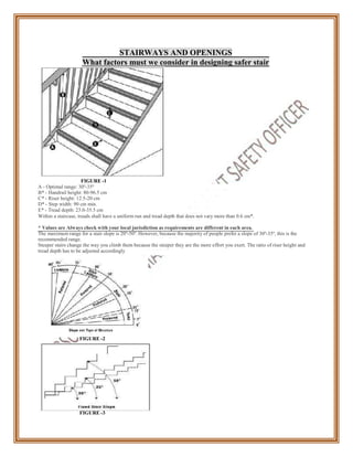
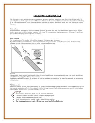
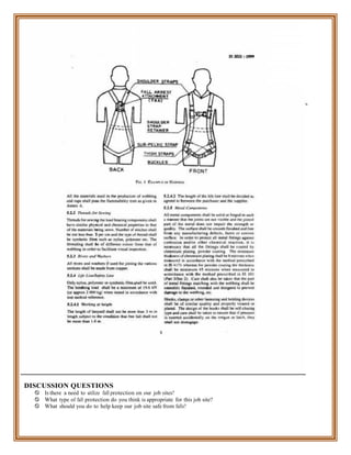
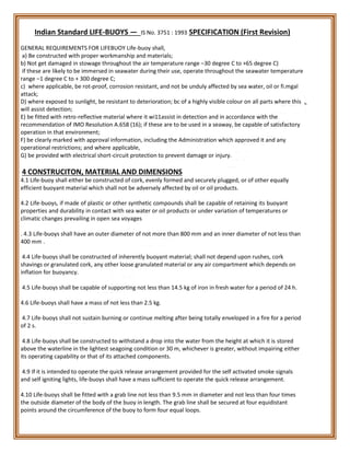
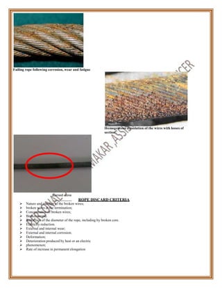
This handbook serves as a workplace s a f e t y and health Tool Box Talk
resource for our team members who are involved in marine construction. This
book highlights general safety precautions to ensure safe practice of our site
oriented operations. This handbook is being developed to assist our team
members and workers to gain and to better understand of our daily
work related safety precautions, their roles and responsibilities, good and bad
practices for daily operations.
This handbook is prepared for awareness and informational purposes.
SAFETY IS A VERY FRAGILE THING.
1
2
TOOLBOX TALKS
TABLE OF CONTENTS
Cold-Related Safety Precautions............................................................................................................5
Driver Safety...............................................................................................................................................6
Ear Protection ............................................................................................................................................8
Electrical Hazards ......................................................................................................................................9
Extension Cord Safety..............................................................................................................................10
Eye Protection ............................................................................................................................................11
Fall Protection ............................................................................................................................................13
Forklift Safety...............................................................................................................................................14
General Safety is Everyone’s Responsibility..........................................................................................16
Hand Held Tools.........................................................................................................................................17
Handling Compressed Gases/Gas Cylinders........................................................................................18
Explosive Act and Gas cylinder Rules......................................................................................19
Heat-Related Illnesses.................................................................................................................................21
Importance of Fire Extinguishers .............................................................................................................22
Basic fire flow formula..............................................................................................................23
Ladder Safety ................................................................................................................................................25
Lockout/Tagout............................................................................................................................................26
Maintaining a Clean Job-Site......................................................................................................................27
Overhead Power Lines...............................................................................................................................28
Personal Protective Equipment ................................................................................................................29
Portable Electric Tools...............................................................................................................................30
Preventing Back Injuries.............................................................................................................................31
Scaffolding......................................................................................................................................................32
Silica Precautions .........................................................................................................................................33
Stairways and Openings .............................................................................................................................34
Short cuts...................................................................................................................................37
Trenching Safety...........................................................................................................................................38
Portable Grinding Operations...............................................................................................39
Horse Play................................................................................................................................40
Signalling Techniques............................................................................................................ .41
Barrication Tape......................................................................................................................43
Horizontal Life Line.................................................................................................................44
Industrial safety belt and harness specification.............................................46
Life Buoy....................................................................................................................................48
Suggested earthing Specification..............................................................................................50
Diving /Under water survey.......................................................................................................51
Tri Pod Rig/PVD Rig..................................................................................................................55
Illumination...................................................................................................................................57
Welding and Cutting......................................................................................................................58
The inspection of wire rope............................................................................................................62
Injury resulting from slip/trip/fall..................................................................................................70
Banksman and signallers...............................................................................................................73
How to read your tyre size ..........................................................................................................75
Basic Information of Marine piling................................................................................................78
Calculation of pp rope breaking strength and SWL........................................................................86
Schedule charges for Disabilities.....................................................................................................87
Accident Investigation 6wh Questions............................................................................................89
PEP Talk Format...............................................................................................................................90
3
COLD-RELATED SAFETY PRECAUTIONS
During the winter months construction workers face an additional occupational hazard - exposure to the cold.
Some health problems can arise including frostbite, trench foot and hypothermia.
Frostbite
Occurs when skin tissue actually freezes and cell damage results. Fingers, toes, cheeks, nose, and ears are primarily
affected. The symptoms of frostbite include an uncomfortable sensation of coldness; there may be a tingling,
stinging, or aching feeling followed by numbness. First aid includes treating affected areas with warm water, Be
careful to avoid rubbing frostbitten areas because this can lead to greater tissue injury. If there is a chance for
refreezing, do not rewarm the affected areas.
Trench foot
Trench foot may be caused by long and continuous exposure to a wet and cold environment or immersion in
water. Symptoms include a tingling and/or itching sensation, pain, and swelling. Blisters may form and be followed
by death of skin tissue and ulceration. First aid treatment for trench foot is similar to the treatment for frostbite,
and includes: moving the victim to a warm area; treating the affected part with warm water (102°-110°F) or warm
packs; arranging bed rest in a warm environment; and obtaining medical assistance as soon as possible.
Hypothermia
The progressive loss of body heat with prolonged exposure to cold defines hypothermia. Body heat loss is
accelerated more rapidly when a person is wet because of sweat or working in a damp environment. The first
symptoms are uncontrollable shivering and feeling of cold. As the body's temperature continues to drop, an
individual can become confused, careless, and disoriented. Individuals experiencing mild hypothermia should be
moved to a warm, dry shelter. Removing wet clothing and applying warm blankets for insulation minimizes further
heat loss. Warm, nonalcoholic, caffeine-free drinks may be offered. More severe cases of hypothermia require
intensive medical care.
Preventing Cold-Related Disorders
 Dress appropriately. Wear s w e a t e r . m o n k y c a p , F u l l s l e e v e w i n t e r j a c k e t , w e a r
a middle layer of wool, and suitable warmest garments. Keep a change of clothes available.
 Protect your feet, hands, head, and face. Keep the head covered (up to 40 percent of body heat can be
lost when the head is exposed).
 Wear footgear that protects against cold and dampness.
 Avoid wearing dirty or greasy clothing because such garments have poor insulating properties.
 Provide a heated shelter for workers who experience prolonged exposure to the equivalent wind-chill
temperature of 20°F or less and shield work areas from windy conditions.
 Use thermal insulating material on the handles of equipment when temps drop below 30°F.
 Allow individuals to set their own pace, work in pairs and take extra work breaks when needed.
 Avoid activities, whenever possible, that lead to heavy perspiration.
 Shift as many outdoor activities as feasible to the inside; select the warmest hours of the day to work
outside.
 Minimize activities requiring sitting or standing in a cold environment for long periods of time.
 Keep energy levels up and prevent dehydration by consuming warm, sweet, caffeine-free, nonalcoholic
drinks and soup.
 Seek warm shelter following these symptoms: heavy shivering, an uncomfortable sensation of coldness,
severe fatigue, drowsiness, or euphoria.
DISCUSSION QUESTIONS
 What are some steps you can take to stay warm and safe when working in cold temperatures?
 What should you do if you have any symptoms of cold related illnesses?
4
ns, s
tivity
s (car
in th
n
DRIVER SAFETY
Many motorists falsely assume that trucker drivers can see the road better because they sit twice as high as the
driver of a car. While trucker drivers do enjoy a better forward view and have bigger mirrors, they still have
serious blind spots.
Rear blind spots
Unlike cars, trucks have deep blind spots directly behind them. The truck driver can't see your car in this position
and your own view of traffic flow is severely reduced. Following too closely greatly increases the chance of a rear-
end collision with a truck.
Side blind spots
Trucks have much larger blind spots on both sides of their vehicles than passenger vehicle
in these blind spots for any length of time, truck drivers can’t see you. Motorists lingering
s). When you drive
ese blind spots
increase the chances of a crash. An excellent rule of thumb for motorists sharing the road with a truck is, "If you
can't see the truck driver in his side mirror, he can't see you."
Truck and van drivers
 Check to see that your mirrors are properly adjusted and clean before you leave. Get help, if necessary.
 Add blind spot mirrors where possible.
 When backing, always get out and scout the area for obstructions, pedestrians, etc. Again, get help where
possible. Try not to rely solely on your mirrors.
 Always remembers three driving hazards a}Roll Over b}Parking Hazards C}Maintena ce Hazards
Top ten tips for driving in a work zone
1. Slowdown! Slower speeds save lives.
2. Turn on your headlights, beacon light,
3. Put your cell phone down.
4. Turn o vehicles back light, parking light, reverse horn which is required.
5. Don’t drink or drive with influence of alcohol.
6. Keep both hands on the wheel.
7. Don’t drive aggressively.
8. Obey work zone directio
9. Watch for work zone ac
afety rules, traffic rules and directions and merge early.
, surroundings workers, machinery ,and other vehicles movement.
10. Pay extra attention driving through work zones after dark, fog, heavy rain and dust full areas.HT tower lines,
Gas pipe lines.
DISCUSSION QUESTIONS
 Where are blind spots on larger trucks located?
 What are some things to keep in mind when driving a truck or van?
 What are three safety tips to follow when driving in a work zone?
5
per
Inside the Vehicle
1. Check Seat Belts
2. Check Mirrors
3. Check horn, head lights, blinkers, and emergency flashers & wipers, reverse horn.
4. Verify backup alarm is working
5. Check fuel gauges.
Pre-Trip & Post Trip Inspection
Take a walk around your vehicle.
1. Windows clean?
2. Lights/signals clean & working.
3. Tires properly inflated / tread wear.0
4. Fluid leaks on the ground.
5. Check the level of coolant in radiator.
6. Check engine oil, steering fluid and hydraulic fluid.
7. Check the battery.
8. Report any broken or defective equipment.
9. Verify back up alarm is audible!.
10. Check belts! Report any worn or loose belts.
At 60 kph one travels 17 meters
• At 80 kph, 22 meters per second.
• At 100 kph, 28 meters per second.
second;
NB: Alcohol, drugs, fatigue, food, illness can affect your Reaction Time thus increasing your stopping
distances.
Maintain Safety distance should not be less than 2 seconds in a light vehicle and 4 SECONDS for
logistics vehicle;
Speed Stopping distance
40 kph 28 m
60 kph 58 m
80 kph 100 m
Motor Vehicles Act, 1988 (Sec: 3) Necessity for driving license.
6
EAR PROTECTION
Imagine what it would be like to live without being able to hear! Hearing enables you to carry on a conversation,
to enjoy your favourite music on your CD player at home or on your truck or car radio. On the job you can
hear the back-up alarms on bi-directional earthmoving equipment, or the warning sound of a crane horn.
More than twenty million INDIANS suffer some measurable hearing loss and sixteen million workers are exposed
to noise on the job that could damage their hearing.Employers to take measures to reduce exposure to noise
levels at or above 90 decibels. The intensity of a sound is measured in decibels (DB). A whisper measures about 20
dB, our average speaking voice is 60 dB, a shop saw is 100 dB and a jet plane is 140 dB.
Many areas around the job site have high noise levels and everyone needs to take the proper steps in preventing
injury to their hearing. First we can try to engineer the noise away by putting up sound barriers or enclosing
certain processes. Second, the company can schedule workers so they spend less time around high noise
operations. Depending on the circumstances, these two options may not be possible to implement but the third
thing we can do anywhere, anytime -- wear hearing protection. Different shapes sizes are available -- ear plugs will
give you some protection, ear muffs provide you with better protection. To achieve maximum protection you
should use both.
Your employer is responsible for requiring the wearing of hearing protection in all operations where there is
exposure to high noise levels. As an employee, your responsibility is to obey warning signs that tell you hearing
protection is required - use common sense -- if the noise is loud, use protection.
Both loud and impulse noise can slowly destroy your hearing. Wearing protection is your best bet against hearing
loss.
DISCUSSION QUESTIONS
 Are there instances on this job site where noises seem particularly loud?
 What types of hearing protection are available to you?
7
System Voltage 11-66 kV 110-132 kV 220 kV 400 kV 800 kV
Low & medium 2.44 3.05 4.58 5.49 7.94
11-66 kV 2.44 3.05 4.58 5.49 7.94
110 – 132kV 3.05 3.05 4.58 5.49 7.94
220 kV 4.58 4.58 4.58 5.49 7.94
400 kV 5.49 5.49 5.49 5.49 7.94
800 kV 7.94 7.94 7.94 7.94
ELECTRICAL HAZARDS
Many people mistakenly think that 110 volts or electricity can't seriously injure or kill a person. However, low
voltage electricity can be extremely dangerous, particularly if you use portable electric tools. One cause of electric
shock when using portable electric tools is the failure of the insulation between the current-carrying part and the
frame of the tool. When insulation fails, fatal electric shock, severe burns or even a fall from one level to another
may result.
Electricity always tries to reach a ground potential and will always take the path of least resistance. If the outer
metal shell of a defective tool becomes energized, the operator sets up a direct path through his own body
between the energized tool and the ground itself. The ground can be the earth or it could be pipes or steel
building structures that are in contact with the earth. Body resistance is lowered when you work in wet areas or
sweat heavily; electricity can then flow easily through vital regions of the body.
When you work in a wet area, near a water pipe, grounded tank, or reinforcing rods that may be grounded, be
extra careful to keep yourself as dry as possible. Stand on a wooden platform or use rubber boots. In places where
tools may become wet, only use tools that are designed especially for that type of service.
Keep portable electric tools in good condition through the use of a regular inspection program. It is your
responsibility to inspect your tools prior to use. Check tools and cords and turn in any that needs repair as soon
as you see a defect.
Inspections
 Ensure all tools and equipment are in good condition.
 Prohibit work on energized electrical circuits.
 Prohibit the use of frayed or worn electrical cords or cables.
 Check portable electric tools before use to ensure that the cord and plug are in good condition.
 Ensure that broken or damaged tools and equipment are removed from service.
 Ensure that portable electrical tools and equipment are either grounded or of the double
insulated type.
 Ensure that each 15 or 20 ampere, 120 volt AC receptacle, not part of the permanent
wiring of the building, is protected by either ground-fault circuit interrupters or an assured
equipment grounding program.
 Ensure that electrical equipment and cords used in wet or damp locations are approved for wet
and damp locations.
 Ensure that listed, labelled or certified equipment is used in accordance with the instructions
included in the listing, labelling or certification.
 Ensure that when a circuit breaker is removed from a circuit breaker panel, it is replaced
with either a breaker or a blank.
 Ensure that unused openings in electrical boxes are effectively closed.
 Prohibit bypassing any protective system or device designed to protect employees from
contact with electrical current.
 Ensure that electrical cords are protected from physical damage.
 Ensure electrical equipment is used only as approved and listed.
DISCUSSION QUESTIONS
 What path does electricity usually take?
 What should you do if you work in a wet area with power tools?
 What are three inspections that are recommended?
STATUTORY CLEARNCES
Minimum Clearances (in meters) between Lines when crossing each other
EXTENSION CORD SAFETY
Nothing about an extension cord suggests danger - there are no moving parts, no flames, no noise. It is harmless
looking, yet it can be extremely dangerous if misused.
Good extension cords should be used all the time - heavy duty rated cords that are approved and tested
by Underwriters Laboratories. Cords that show wear should be repaired or thrown out.
There are some hazards in using extension cords that only you can control. First of all, no extension cord can
stand rough usage. If you kink it, knot it or crush it and even bend it, you can break the insulation, which may cause
a short circuit and a fire or even an electric shock.
Most cords used carry regular 110-volt electricity. Now, no doubt at some time you have received a shock from a
110-volt line without serious harm - just a great tingling sensation. But even a 10-volt current can
kill. It is not harmless. The conditions, however, must be right. The right conditions may consist of making a good
connection with a live wire carrying a 110 voltage with wet or sweaty hands, and standing or lying on the
ground, a wet floor, a water pipe or another electrical connection.
So, protect the extension cords you use. Coil them in large loops, not in close kinked coils. Don’t bend them
unnecessarily. Don't repair them yourself.
In special situations, special types of cords are needed. Some cords are water-resistant, others are not. Some are
insulated for heat resistance; others are designed to stand the action of solvents and other chemicals that may be
present.
These rules should be applied for the safe use of extension cords:
 Inspect all extension cords at the beginning of each workday for any signs of wear or damage. Remove any
worn or damaged cords from service immediately.
 Before each use, check the cord for the presence of a ground blade on the male end of the cord.
 Handle the cord gently, avoiding strain, kinking, crushing or cutting.
 String it where it will not be hit or tramped on.
 If moisture, heat or chemicals are present, be sure your cord is the proper type to resist the conditions
that are present.
 Extension cords should not be used as ropes to raise and lower tools and materials.
DISCUSSION QUESTIONS
 Where do our tagged and unused tools and extension cords go?
 Do you know what the proper storage is for extension cords?
EYE PROTECTION.
Take time to select the right kind
To protect the eyes from nails, wood chips, metal shavings, dusts, acids, and construction related
flying particles and chemicals, wear the appropriate eye protection. Depending on the job, you might
wear safety glasses, goggles or a full-face shield. Today, we have eye protection available that will suit
every type of exposure. People who wear glasses with corrective lenses may need prescription safety glasses or
goggles that can be worn over their regular glasses for protection against damage or breakage.
Basically, there are four types of particles that cause eye injuries on the job:
Unidentified flying objects - These microscopic objects consist of dust and particles floating around in the
air, generally by wind, equipment or cleaning operations. When working in dusty conditions,
(CementGodown,cement feeding point) wear eye protection. Even a small speck in the eye can lead
to trouble.
Particles resulting from chipping, grinding, sawing, brushing, hammering or using
power tools - These particles move at an amazing speed and strike with the force of a bullet.
Wear eye protection any time overhead operations are performed. Some jobs may require safety goggles under
a full face shield.
Invisible Hazards - You can’t see the injurious light rays generated by welding operations or laser
beams and their effects are often not felt until hours later. Wear the appropriate eye protection required when
using this equipment; if you happen to be working nearby, don't look in the direction of welding arcs or
where a laser beam is being used.
Liquids - Hot liquids, such as tar or asphalt, solvents, paint and solutions for cleaning masonry or metal can
cause serious eye injury if splashed in your face. The use of proper eye protection, possibly a full face shield, is
essential when transferring liquids between containers and when using caustic or acid cleaners.
When to use eye protection
There are many operations on construction projects where it's mandatory for workers to wear eye protection.
The following is only a partial list:
 Cutting construction materials with any type of power tool.
 Using pneumatic and powder-actuated nailguns.
 Using of manual impact tools, such as hammers.
 Chipping, sledging and hammering on metal, stone and concrete.
 Caulking, brushing, and grinding.
 Drilling, scaling and scraping.
 Gas welding, cutting, brazing, soldering.
 Electric arc welding and cutting, and other operations which subject the eyes to flying
particles, dust, hot liquids, molten substances, gases, fumes and liquids.
 Handling of acids, caustics and creosoted materials.
 Handling of hot tar.
EYE PROTECTION (con’t)
Some workers object to eye protection because it fogs up. Fogging occurs because sweat vaporizes and coats the
inside of the lens. Wear a handkerchief or sweatband around your forehead to keep perspiration off your eye
protection or use anti-fog eye protection or an anti-fog liquid coating.
DISCUSSION QUESTIONS
 Are there any operations on this construction project that would require safety glasses, goggles, or other
eye protection?
 Do you personally know of anyone who has had an eye injurybecause they were not wearing eye
protection?
 From which person in this company do we obtain our eye protection devices when needed?
FALL PROTECTION
Falls are one of the most devastating types of injuries on a job site. When fall protection is in place and used
properly, falls and fall-related injuries can be prevented. There are several types of fall protection available;
guardrail systems also aid in fall prevention.
Fall prevention practices
 Assess the jobsite to determine if the walking and working surfaces have the strength and structural
integrity to safely support workers.
 Workers exposed to falling six feet or more from an unprotected side or edge should be protected
by a guardrail system, safety net system or personal fall arrest system.
o A personal fall arrest system consists of an anchorage, connectors, body harness, and may
include a lanyard, deceleration device, lifeline or a suitable combination.
 Workers in a hoist area exposed to falls of six feet or more should be protected by either a guardrail
system or personal fall arrest system.
 Employees exposed to a floor opening more than six feet above lower levels should be protected by
personal fall arrest systems, covers or guardrail systems.
 Employees using ramps, runways and other walkways should be protected from falling six feet or more by
a guardrail system.
 Employees engaged in roofing activities on low-slope roofs with unprotected sides and edges six feet or
more above the lower level should be protected from falling by a guardrail system, safety net, personal fall
arrest system, or a combination warning line system and guardrail system, warning line system and safety
net system, warning line system and personal fall arrest system, or warning line system and safety
monitoring system.
 Employees engaged in roofing activities on steep roofs with unprotected sides and edges six feet or more
above the lower level should be protected from falling by a guardrail system with toeboards, safety net or
personal fall arrest system.
Guardrails
Guardrails protect you from falls that can seriously injure or even kill. The amount of protection guardrails provide
depends on how they are constructed and maintained. Most guardrails are built of strong materials and are usually
solid when first put up. However, guardrails often are abused, weakened, broken or removed and not replaced.
Weakened guardrails are sometimes more dangerous than no guardrails at all because they give a false sense of
security.
As you go about your job
 Get into the habit of checking guardrails.
 If you discover a weakened or a missing rail or section, correct the situation if you can or report it so that
the hazard can be eliminated.
 If you bump a rail with material or equipment, check to see if it is weakened.
 If you discover a broken rail, upright or toeboard, repair it if you can. Otherwise, report it so that it can
be repaired.
 When repairing or replacing guardrails, use caution as you are exposed to the very danger that you are
providing protection against.
DISCUSSION QUESTIONS
 Is there a need to utilize fall protection on our job sites?
 What type of fall protection do you think is appropriate for this job site?
 What should you do to help keep our job site safe from falls?
FORKLIFT SAFETY
Training and certification requirements
Only trained and certified forklift operators are allowed to operate the forklift. The employer may create and
implement a written forklift operator training program and perform training internally (operating rules should be
posted and enforced). Operator recertification is required every 3 years.
Picking up a load
 "Square up" on the center of the load and approach it straight on with the forks in the travel position;
stop when the tips of your forks are about a foot from the load.
 Level the forks and slowly drive forward until the load is resting against the backrest of the mast.
 Lift the load high enough to clear whatever is under it.
 Back up about one foot, then slowly and evenly tilt the mast backwards to stabilize the load.
Putting a load down
 "Square up" and stop about one foot from the desired location.
 Level the forks and drive to the loading spot; slowly lower the load to the floor.
 Tilt the forks slightly forward so that you do not hook the load.
 When the path behind you is clear of obstructions, back straight out until the forks have cleared the
pallet.
Stacking one load on top of another
 Stop about one foot away from the loading area and lift the mast high enough to clear the top of the
stack.
 Slowly move forward until the load is squarely over the top of the stack.
 Level the forks and lower the mast until the load is no longer supported by the forks.
 Look over both shoulders for obstructions and back straight out if the path is clear.
Lifting
 Do not exceed the lift capacityof the forklift; read the lift capacityplate on the forklift if you are unsure.
Follow the manufacturer's guidelines concerning changes in the lift capacity before adding an attachment.
 Lift the load an inch or two to test for stability; if the rear wheels are not in firm contact with the floor,
take a lighter load or use a forklift that has a higher lift capacity.
 Do not raise or lower a load while you are en route; wait until you are in the loading area and have
stopped before raising or lowering the load.
 After picking up a load, adjust the forks so that the load is tilted slightly backward for added stability.
Raise the forks an additional two inches to avoid hitting or scraping the ramp surface as you approach the
ramp.
Loading docks
 Keep the forklift clear of the dock edge while vehicles are backing up to the dock.
 Do not begin loading or unloading until the supply truck has come to a complete stop, the engine has
been turned off, the dock lock has been engaged and the wheels have been chocked.
 Do not drive the forklift into the truck until the bridge or dock plate has been attached.
 Do not drive the forklift into a truck bed or onto a trailer that has "soft" or loose decking or other
unstable flooring.
 Drive straight across the bridge plates when entering or exiting the trailer and use dock lights or
headlights when working in a dark trailer.
FORKLIFT SAFETY (con’t)
Safe Practices
 Ensure substantial overhead protective equipment is provided on high lift rider equipment.
 Ensure each industrial truck has a warning horn, whistle or other device that can be
clearly heard above the normal noise in the area.
 Ensure the brakes on each industrial truck are capable of bringing the vehicle to a
complete and safe stop when fully loaded.
 Ensure the truck’s parking brake will prevent the vehicle from moving when unattended.
 Ensure that industrial trucks operating in hazardous areas (e.g., where flammable
gases or vapors, combustible dust or ignitable fibers may be present) are approved
for such locations.
 If industrial trucks with internal combustion engines operate in buildings or enclosed areas,
carefully check to ensure such operations do not cause harmful concentration of dangerous
gases or fumes.
 Prohibit employees from riding on the lift truck unless a seat is provided; use seatbelts.
Each rider must have a seat and not ride on sides or forks.
 Do not remove passenger compartment guards or rollover protection devices; do not
use people as counterweights.
 Do not use bare forks as a man-lift platform. Utilize a manufactured man-lift basket,
securely attached to the forklift for the lifting of workers. Never move the forklift with
personnel in the basket. The worker is to wear a harness secured to the basket at all
times during the lift.
 Approach railroad tracks at a 45° angle when driving the forklift.
 Steer the forklift wide when making turns and sound the forklift horn when
approaching blind corners, doorways or aisles to alert other operators and
pedestrians.
DISCUSSION QUESTIONS
 Where are our forklift operating rules and procedures posted?
 Who is certified as a forklift operator on this jobsite?
GENERAL SAFETY IS EVERYONE’S RESPONSIBILITY
Safety is everyone's responsibility! As an employee, you should:
Learn to work safely and take all rules seriously.
Recognize hazards and avoid them.
Report all accidents, injuries and illness to your supervisor immediately.
Inspect tools before use to avoid injury.
Wear all assigned personal protective equipment.
On the other hand, it is management's responsibility to:
Provide a safe and healthy workplace.
Provide personal protective equipment.
Train employees in safe procedures and in how to identify hazards.
Everyone must be aware of potential hazards on the job:
Poor housekeeping results in slips, trips and falls.
Electricity can cause shocks, burns or fire if not handled properly.
Poor material handling may cause back problems or other injuries.
Tools and equipment can cause injuries if guards or protective devices are disengaged.
Always use the protections that are provided on the job:
Guards on machines and tools keep body parts from contacting moving equipment.
Insulation on electrical equipment prevents burns, shock and fire.
Lockout/tagout assures equipment is de-energized before it is repaired.
Personal protective equipment shields your body from hazards you may face on the job.
In case of emergency:
Understand alarms and evacuation routes.
Know how to notify emergency response personnel.
Implement a procedure for leaving the scene safely so emergency personnel can do their job.
Wipe up spills promptly and correctly.
Safety benefits everyone! By incorporating safety rules, employees avoid injuryas well as illness from exposure to
hazardous substances. With fewer injuries, a business can be more productive and profitable.
The welfare of the community is also enhanced by providing cleaner air and water and less chance of dangerous
accidents that can put lives and property at risk.
DISCUSSION QUESTIONS
What are three things you can do to make our job site safer?
What are three things management should do to make our job site safer?
What are several potential job site hazards you should be aware of?
HAND HELD TOOLS
Keep all hand tools in good condition. Check to be sure that safety devices are in place and in proper working
order. Lubricate your tools on a regular schedule. Keep them sharp and they will help you perform your job safely.
Typical hand tools include hammers, wrenches, screwdrivers, hand saws, axes, hacksaws, shovels, rakes, come-a-
longs, picks, sledge hammers, wheelbarrows, levels, knives, punches, chisels, pliers, etc. Each has a particular job to
do and it's your responsibility to use the tool as the manufacturer designed it. Short cuts using the wrong tool will
often cause an accident. A perfect example of this is using a screwdriver to pry with when the right tool is a pry
bar.
When using hand tools remember to wear the proper personal protective equipment. If there is any potential for
an eye injury, safety glasses are a must. Protect your hands by wearing gloves. Watch out for sharp pointed tools
as well as sharp edges on saws -- both will cause a nasty cut if handled improperly. If you have any question about
what to wear ask your supervisor.
After you're done with a hand tool return it to the place it belongs. This may be your own tool box or belt, or it
may be back in the tool trailer or gang box. When you return it, place it properly so that the next person can pick
it up without the possibility of injury. Should a tool get damaged take it out of service for repairs, and if it can't be
repaired, dispose of it. Defective tools are dangerous and should not be used.
Inspections
 Replace hand tools, such as chisels and punches,that develop mushroomed heads.
 Replace hammers, axes and similar tools that have broken or fractured handles.
 Ensure tool handles are wedged tightly in the head of all tools.
 Ensure tool’s cutting edges are kept sharp.
 Ensure appropriate safety glasses, face shields, etc. are used while using hand or powered tools or
equipment that might produce flying materials or is subject to breakage
Hand tools make your job much easier. Care for them properly and use them wisely.
DISCUSSION QUESTIONS
 Have you checked your toolbox recently for damaged tools?
 Do you always use the right tool for the job, even if the job takes only a few seconds?
HANDLING COMPRESSED GASES/GAS CYLINDERS
You probably can’t find many job areas where oxygen and acetylene cylinders are not on hand for cutting and
welding. In manycases, these cylinders aren’t properly stored and handled all the time. They are used so often that
it's easy to be careless with them.
To help prevent accidents
 Use a cradle or cage when hoisting cylinders with a crane.
 Close valve and release gas from the regulator before a regulator is removed.
 Be sure the regulators are removed and valve protection caps are on before moving cylinders and while
the cylinders are in storage.
 Keep cylinders upright and secured at all times.
 Close the valve on empty cylinders, put on the cap, and mark them "MT."
 Store oxygen cylinders at least 20 feet away from any fuel/gas cylinders, such as
acetylene.
 Do not store propane cylinders inside any building.
 Do not use cylinders for rollers or supports.
 Do not tamper with the valves or safety devices
 Keep all cylinders, cylinder valves, couplings, regulators, hoses and apparatuses free of oilyor greasy
substances.
 Never crack a fuel gas cylinder valve near sources of ignition.
 Examine compressed gas cylinders regularly for signs of defects, deep rusting or leakage.
 Only use pressure-reducing regulators for the gas and pressures for which they are intended.
 Open cylinder valves slowly and carefully.
 When a cylinder wrench is needed on the valve, keep the wrench nearby to turn off the valve quickly if
necessary.
 Use red to identify the acetylene (and other fuelgas) hose, green for oxygen hose,
and black for inert gas and air hose.
 Only qualified technicians should clean or repair a regulator.
 Do not tamper with the relief valve or remove it from a regulator.
 Read MSDS’s and train about fuel gases.
 Never allow oxygen to contact oil, grease or other flammable substances.
 Never use oxygen as a substitute for compressed air.
 Never use oxygen to dust off clothing, in pneumatic tools or for ventilation.
DISCUSSION QUESTIONS
 What is the procedure to prepare to move or store a gas cylinder?
 When gas cylinders are empty, how do we mark them and where are they stored?
 What colors identify the different hoses?
EXPLOSIVE ACT 1884 AND GAS CYLINDER RULES 2004 “Dissolved
acetylene cylinder” means a cylinder having a valve and with or without safety devices containing a
porous mass, a solvent for the storage of dissolved acetylene and at least sufficient acetylene to saturate the
solvent at atmospheric pressure and at a temperature of +15Degre C;
Explanation.-Acetone or any other solvent used shall not be capable of chemical reaction with the acetylene
gas or with the porous mass or with the metal of the cylinder or valve;
“Poisonous (toxic) gas” a gas which has a maximum allowable concentration in air for human respiration
not exceeding 100 mg/m absolute pressure;
Additional requirements for dissolved acetylene gas cylinders— Dissolved acetylene gas cylinder
shall comply with following additional provisions, namely:-
(i) The porous substance shall fill as completely as possible the cylinder into which the acetylene is
compressed.
(ii) The porosity of the substance shall not exceed 92 per cent and in no case shall be less than 75 per cent.
(iii) Any solvent used shall not be capable of chemical reaction with the acetylene gas or with the porous
substance or with the metal of the cylinder.
(iv) If acetone is used as a solvent it shall comply with the requirements of IS: 170, the quantity of acetone
including the gas in solution shall be such that the cylinder meets the requirements of additional tests
specified in IS: 7312.
(v) The valves of the cylinders shall not contain more than 70 per cent copper in their composition.
(vi) The pressure in the cylinder shall not exceed 16 kgf/cm2 at a temperature of15DegreeC.
(vii) Every cylinder shall before being filled with porous mass be tested by hydrostatic pressure to a pressure
of not less than 60 kgf/cm2. This pressure may be reduced to 53 kgf/cm2 if the cylinder is fitted with fusible
plug. No cylinder which shows a permanent stretch in excess of 7½ per cent of the total stretch suffered
during hydrostatic stretch test shall be allowed.
(viii) The safety relief devices if fitted, shall operate at a pressure of 53 kgf/cm or at a temperature of 100
Degree + 4degreeC/–2degreeC.
(ix) Every cylinder shall have permanently and conspicuously marked upon it or upon a brass plate soldered
to it the name of the manufacturer and the words
“Acetylene properly compressed into porous substance” and shall bear the following markings, namely:-
(a) Serial number and identification of manufacturer;
(b) Number of the standard;
(c) Test pressure;
(d) The date of hydrostatic stretch test with code mark of the place where the test was carried out;
(e) Date of filling of porous mass;
(f) Water capacity’;
(g) A symbol to indicate the nature of heat treatment;
(h) Identification of porous mass and porosity percentage;
(i) Tare weight (inclusive of valve);
(j) Inspector’s official mark;
(k) Maximum gas capacity.
Examination of dissolved acetylene cylinders before filling: —Whenever a cylinder is charged with
acetylene, it shall be subjected to a thorough visual examination in accordance with IS:8433, if the history
of the cylinder shows that it has not been subjected to such an examination within the previous two years
and at the same time the valves shall be removed and the conditions of the porous substance at the neck of
the cylinder ascertained:
Provided that this period of periodical examination shall be one year in case the cylinders are filled with
loose porous mass.
No licence needed for filling and possession in certain cases: —In Rule 43, no licence
shall be necessary for
- (i) liquified petroleum gas when the total quantity of gas does not exceed 100 kg at a time;
(ii) any other flammable but non-toxic gas when the total number of cylinders containing such gas does
not exceed 25 or the total weight of gas does not exceed 200 kg., whichever is less, at a time;
(iii) any non-flammable non-toxic gas when the total number of such cylinders does not exceed 200 at a
time;
(iv) any toxic gas when the total quantity of such cylinders does not exceed 5 at atime;
(v) acetylene gas contained in cylinders in dissolved state when the total quantity of such
cylinder does not exceed 50 at a time
The following distances shall be kept clear at all times, between any building, public place,
public road or any adjoining property which may be built upon and the storage shed used for
the storage of liquefied petroleum gas cylinder:
Quantity of compressed gas in Cylinder Minimum distance to be kept clear
Kg. Metres
0 --101 --
101 -- 2000 3
2001 -- 3000 4
3001 -- 4000 5
4001 -- 6000 6
6001 -- 8000 7
8001 -- 10000 8
10001-- 12000 9
1200 -- 20000 12
over 20000 15
Calibration. —Calibration of equipment shall be carried out at periods not exceeding the
following—
(i) Working pressure gauge -1 month.
(ii) Master pressure gauge- 6 months.
(iii) Weighing equipment-checked by test weight daily when in service.
(iv) Test weights – 2 years.
Identification colours specified in IS:4379 for industrial cylinders and IS:3933 for medical cylinders.
INDIAN ORIGIN-
(a) Cylinders
Welded low carbon steel cylinders for low pressure liquefiable gases manufactured to
IS:3196 Part 1, Part 2 & Part 4, IS:7142, auto LPG containers to IS:14899, DA cylinders
to IS:7312 certified by Bureau of Indian Standards.
HEAT RELATED ILLNESS
There are a number of heat related illnesses including heat stroke, heat exhaustion and heat cramps.
Heat stroke
The most serious health problem for workers in hot environments is caused by the failure of the body's internal
mechanism to regulate its core temperature. Sweating stops and the body can no longer rid itself of excess heat.
Signs include mental confusion, delirium, loss of consciousness, convulsions or coma; body temperature of 106°F
or higher; hot dry skin which may be red, mottled or bluish. Victims may die unless treated promptly. Medical help
should be called and the victim must be moved immediately to a cool area and his or her clothing soaked with cool
water. He or she should be fanned vigorously to increase cooling.
Heat exhaustion
Develops as a result of fluid loss through sweating when a worker has failed to drink enough fluids, take in enough
salt or both. A worker with heat exhaustion still sweats, but experiences extreme weakness or fatigue, giddiness,
nausea or headache. The skin is clammy and moist, the complexion pale or flushed, and the body temperature
normal or slightly high. The victim should rest in a cool place and drink salted liquids.
Heat cramps
Painful spasms of the bone muscles, are caused when workers drink large quantities of water but fail to replace
their body’s salt loss. Cramps may occur during or after working hours and may be relieved by taking salted liquids
by mouth or saline solutions intravenously for quicker relief, if medically determined to be required.
First aid for most heat illnesses
 Act quickly and move the victim to a cool, shaded area to rest. Don’t leave the person alone.
 If symptoms include dizziness or light-headedness, lay the victim on his or her back and raise
his or her legs six inches to eight inches.
 If symptoms include nausea or upset stomach, lay the victim on his or her side.
 Loosen and remove heavy clothing.
 Have the person drink cool water (a cup every 15 minutes) unless sick to the stomach.
 Cool the person’s body by fanning and spraying with a cool mist of water or applying a wet cloth to the
person’s skin.
 Call emergency help if the person does not feel better in a few minutes.
Safe Practices
 Do heaviest work during coolest part of day and work people in pairs.
 Build up tolerance to the heat and the work activity slowly. Most people need two weeks to adjust.
 Drink plenty of cool water, about a cup every 15 minutes.
 Wear light, loose-fitting, breathable clothing.
 Take frequent short breaks in cool shaded areas to allow the body to cool down.
 Avoid eating large meals and drinking alcoholic or caffeinated beverages before hot work.
Risk Factors
 Taking certain medications. Check with your pharmacist to see if any medicines you are taking affect you
during hot work.
 A previous heat-induced illness.
 Personal protective equipment that can add to physical stress.
DISCUSSION QUESTIONS
 What are our company procedures for working in hot conditions?
 What are you supposed to do if you have symptoms of a heat related illness while working?
IMPORTANCE OF FIRE EXTINGUISHERS
In the event of a fire, the correct use of a fire extinguisher could mean the difference between suffering a minor
loss or a major one. There are several things to consider when using fire extinguishers. You must know the class
of fire involved and the correct type of fire extinguisher to use.
Classes of fires and fire extinguishers
Class A fire: Involves ordinary combustibles such as paper, wood, cloth, rubber or plastics. The
common extinguishing media is water or dry chemical. These types of extinguishers are usually placed in
and around buildings.
Class B fire: Flammable liquids, grease or gases are covered under this category.
Common extinguishing media are foam, carbon dioxide or dry chemical. These types of extinguishers are usually
found in vehicles or mounted to or placed beside machinery, equipment and containers of flammable liquid.
Class C fire: Live electrical fires are class C fires. CO2 or dry chemical extinguishers should be used.
However, the actual burning product may be class A items.
Class D fire: Burning materials include combustible metals such as magnesium and sodium. Special
extinguishing agents, approved by recognized testing laboratories, are needed when working with these metals.
Responding to fires
When responding to a fire:
 Sound the fire alarm
 Call the local fire department immediately
 Follow your company's procedures on responding to fires
Attempt to fight the fire only if:
 You know the type of combustible material burning
 You have been trained to use the fire extinguisher correctly
 If the fire is still in the beginning stage. If the fire gets too large or out of control, evacuate immediately.
Remember P-A-S-S when using an extinguisher
P - Pull. Pull the locking pin before using the fire extinguisher.
A - Aim. Aim the fire extinguisher at the base of the fire; not at the flames or smoke.
S - Squeeze. Squeeze the lever of the fire extinguisher to operate and discharge.
S - Sweep. Sweep the fire extinguisher back and forth at the base of the fire to extinguish.
(Most extinguishers will only allow about 10-seconds of extinguishing media.)
Prevention is the key when it comes to fire fighting. Good housekeeping, proper storage procedures and safe work
practices will go a long way toward reducing the likelihood that a fire will destroy valuable property or injure
either you or a fellow employee.
DISCUSSION QUESTIONS
 What type(s) of fire extinguishers are located in your work area?
 How do you operate them?
 What is your company's policy on sounding an alarm and contacting the fire department?
 What kinds of flammables are most likely to create a fire danger at your jobsite?
 What type of fire extinguisher should be used on those flammables or combustibles?
Basic Formula:
BASIC FIRE FLOW FORMULA
Needed Fire Flow (NFF) = Length X Width X Percentage of fire involvement
3
Example:
1. To calculate the total fire flow for an entire building involved in fire:
2.To calculate the needed fire flow for a portion of the building involved in fire. In this
example 25% of the entire structure is involved in fire:
1 For additional floors, multiply the percent involved times the number of floors involved.
BASIC FIRE FLOW FORMULA
Exposures
Exposures are classified as internal (additional floors above the fire) or external (buildings
adjacent to the involved structure).
1. For internal exposures (additional floors), a constant factor of 25% is added for each
exposure (to a maximum of 5 floors) to Needed Fire Flow. Therefore the Exposure
Formula is:
Length X Width+ 25% for each floor above the fire (maximum of 5 floors)
3
This example shows the exposure of 2 additional floors
above the fire (add 25% for each floor) to the NFF
2. For External Exposures (building adjacent to the involved structure), a constant factor of 25% is
added for each side that has an exposure. Therefore the Exposure Formula is:
Length X Width + 25% for each side with an exposure
3
This example shows exposures on the B and C side of the structure (add 25% for each side with an
exposure) to the NFF
LADDER SAFETY
One of the most commonly used, often abused, and least noticed piece of equipment on the josite may present a
major hazard – the ladder. Out of 150 construction accidents involving ladders, the following were principal
contributing factors:
 Climbing or descending improperly
 Failure to secure the ladder at top and/or bottom
 Carrying objects while climbing or descending
 Structural failure of the ladder
Commercial ladders are constructed properly and are of sound material. However, after they have been in use for
a while they may become damaged through abuse, rough handling while moving, being struck by heavy objects, etc.
Basic Ladder Safety Information
Hazards - Be aware of broken or missing parts, energized electrical lines or equipment, ladders too short for
work height, weight limit rating too low, not the correct equipment for job.
Loads - Self-supporting (foldout) and non-self-supporting (leaning) portable ladders must support four times the
maximum intended load; extra-heavy duty metal or plastic ladders must sustain 3.3 times the maximum intended
load.
Angle - Ladders should be set at the proper angle 75 degree. The base of a non-self-supporting commercially
manufactured ladder should be one-quarter its length away from the wall or supporting structure.
Rung - Rungs, cleats or steps must be parallel, level and uniformly spaced and must be spaced between 10 inches
and 14 inches apart; spacing for extension trestle ladders must be 8 inches to 18 inches for the base, and 6 inches
to 12 inches on the extension section, shaped so that an employee’s foot cannot slide off. .
Length of ladder (feet) over lap (feet)
Up to and including 36 3
Over 36 upto and including 48 4
Over 48 and up to 60 5
Storage - Store ladders so they will not warp, sag or be damaged and secure them during transport.
Inspection - Check to ensure shoes and ladder are free of oil, grease, wet paint and other slipping hazards;
warning labels are legible; spreader device can be locked in place and ensure area around the top and bottom of
ladder is cleared of material.
Safe Practices
 Face ladder and hold on with both hands when climbing
 Carry tools on belt or use hand line to move tools and materials to your work area
 Hold on with one hand when performing work
 Never reach too far to either side or rear
 Do not climb higher than second step from top on a stepladder or third from the top on a straight ladder
 Never attempt to move, shift or extend ladder while in use
 Secure ladders at either the top or the bottom or use a spotter (someone at the bottom) to keep the
ladder stable
DISCUSSION QUESTIONS
 Have all workers been trained in the proper setup and use of ladders?
 Are the ladders on this job in good condition and are they properly used?
 Is the ground where the ladder is to be used stable?
 Are there ropes available on the site for securing the ladders and for use as hand lines?
LOCKOUT/TAGOUT
Lockout/Tagout (LOTO) is a way to ensure that electricity or other energy is not turned on (or released) while
someone is working on machinery. Simply turning off a power switch is not enough. You must de-energize
(prevent equipment from starting or moving), lock it out, release stored energy (for instance, bleed air from a
pneumatic hose), and test to make sure the energy is offbefore working on the piece of equipment.
Lockout/Tagout Procedures
 Each piece of equipment or machinery should have its own LOTO procedures.
 Notify operators and supervisors that power is being disconnected or isolated.
 Prepare for isolation by checking for specific written procedures that state the shutdown and restart
process.
 Shut down by turning off the equipment.
 Separate all energy sources using proper isolating devices—like manual circuit breakers or disconnect
switches.
 Pushbuttons or selector switches cannot be the only wayto de-energize. Equipment may have more than
one type of energy that needs to be isolated.
 Each worker who can be exposed to hazardous energy must be part of the LOTO process.
 Control stored energy (e.g., discharge capacitors or drain hydraulic lines).
 Verify equipment has been de-energized by trying to restart and using testing equipment (such as an
electric circuit tester).
 Only the worker who puts on a lockout or tagout device may remove it.
 When the work is finished, inspect to ensure all tools, mechanical restraints, and electrical devices have
been removed before you turn on power. Warn affected employees that power will be restored.
 If the LOTO job is interrupted for testing or positioning equipment, the procedures must start over from
the beginning.
DISCUSSION QUESTIONS
 Do you know what our lockout/tagout procedures are?
 Do you know how to complete the lockout/tagout procedure for equipment that you are individually
responsible for?
LOCK OUT LOCK OUT AND TAG OUT TAG OUT AND LOCK OU
MAINTAINING A CLEAN JOB-SITE
Maintaining a neat and clean jobsite means different degrees of cleanliness and neatness to different people. What
one person accepts as proper “housekeeping” may not be acceptable to someone else.
Clean job sites are influenced by two things: What we do or neglect to do and the weather. We can control most
conditions; others, we can be on the lookout for and guard against or remove. While we can't prevent bad
conditions caused by the weather, we can often foresee them and plan the necessary action.
A general cleanup once a week won’t guarantee safety on a construction site. You've seen jobs where it wasn’t safe
to turn around or even put your foot down without looking twice to be sure there wasn't something that might
cause an accident. A job like this is poorly run. Not only is it unsafe, it also makes for poor relations with the
owner and the public.
Safe Practices
 Keep trash and loose materials picked up and disposed of properly; put scrap in its proper place
 Secure materials to prevent shifting or rolling.
 Remove tripping hazards.
 Store materials so there is always a clean path around and between work areas and in and out of the
jobsite. Do not place objects in ways of exits.
 Keep floors, ladder rungs and stairways dry and free from oil and grease.
 Put tools and equipment in areas where they belong.
 Do not store loose materials on scaffolds./walk way/work platform/unguarded edge .
 Do not store more than one shift of material (e.g., block or brick) on scaffolds.
 Store material for stable removal.
 Leave space for workers and equipment to load and unload stored materials.
 Ensure the platform, scaffold or support has adequate strength for the weight of material.
 Keep the height of stored material low for stability and line of sight.
 Clear scrap lumber with protruding nails from work areas, passageways and stairs in and around buildings
or other structures.
 Remove combustible scrap and debris regularly.
 Provide containers for the collection of waste, trash, oily and used rags, and other refuse.
 Ensure containers for oily, flammable or hazardous wastes (such as caustics and acids) are equipped with
covers.
 Do not drop material outside the exterior walls of the building or structure.
 Enclose material chutes.
 Guard openings and discharge of material chutes.
 Don't leave open containers of flammables: gasoline, paint, oil, grease, adhesives, etc.
 Ensure the site has good lighting. Replace lights immediately when they burn out.
 Remember if waste is allowed to accumulate for just a few days, the job becomes messy and unsafe.
REMEMBER 5S PRACTIVE IS THE BEST KEY OF MAINTAINING A CLEAN JOB SITE
DISCUSSION QUESTIONS
 Is there any area on this job that presently needs a clean-up?
 Are the trash containers on this job adequate and are they being used?
 Is there a designated area on the jobsite for construction debris to be placed?
OVERHEAD POWER LINES
Contact between crane booms and power lines cause more fatalities each year than any other type of electrical
accident in the construction industry. Examples of these types of accidents include:
 A framer hooked onto a bundle of material stored under a power line and was guiding the load when the
boom hit the line.
 A foreman walking backward pulling the hook when the load line contacted an overhead power line.
 A worker was leaning against the side of the crane when the boom hit a power line causing the current to
ground through his body.
It is difficult for the boom operator to be sure of the exact location of the boom tip. The operator doesn't have
good distance judgment looking up along the boom and is usually paying attention to the load.
The best way to avoid contact is to keep the boom at least 10 feet awayfrom any overhead line. This
may mean storing material in a location that is less convenient than the empty ground under the wires, that
someone has to be assigned to watch the boom tip when work approaches a power line or that the power
company should de- energize a line or protect it with rubber sleeves.
Safe practices
 Survey the site for overhead power lines—LOOK UP!
 Locate and identify overhead electrical power lines.
 Remember when using a crane or high reaching equipment near energized power lines of 50,000 volts
(50 Kv) or more, the minimum distance between the lines and any part of the crane/equipment
must be10 feet plus ½ inch for each 1,000 volts over 50,000 volts.
 Request an observer when you do not have a clear view of the power line from your operating station.
The observer’s only job should be ensuring that the operator maintains a safe distance from overhead
power lines.
 Always treat overhead power lines as if they are energized.
 When in doubt, contact the electric company to determine what voltage is on the lines.
 Always ask the electric company to either de-energize and ground the lines or install insulation while you
are working near the lines.
 Even with insulation, a minimum safe clearance must be maintained from the power lines.
 Always make sure ladders and tools used near power lines are nonconductive.
DISCUSSION QUESTIONS
 Do we have any material stored, or work to be done, close to a power line on this job?
 Is there anyone here qualified to give CPR to a worker rendered unconscious by electric
Voltage(Phase to Phase) Minimum Clearance(Feet)
< - 50,000 10
50,000 - 75,000 11
75,000 - 125,000 13
125,000 - 175,000 15
175,000 - 250,000 17
250,000 - 370,000 21
370,000 - 550,000 27
550,000 - 1,000,000 42
PERSONAL PROTECTIVE EQUIPMENT
Hazards should be avoided through engineering or administrative controls. If those controls are not available or
are unfeasible, personal protective equipment should be used to put a barrier between you and the hazards.
Types of Personal Protective Equipment
Hearing protection – Use when exposed to noise at or above, 90 decibels (dB)TWA. If you have to yell to
communicate, you need hearing protection.
Hard hats – Wear when exposed to bumping into or struck-by hazards.
Gloves and arm protection – Cover hands and arms when exposed to chemicals, heat, cold, radiation agents
or abrasive surfaces.
Respirators – Should be used when exposed to harmful inhalation hazards due to chemicals. Respirators have
intended uses; ensure the respirator you are using is properly selected for the hazard to which you are exposed.
For example, dust respirators are used for silica exposure when cutting block; organic cartridge respirators are
appropriate for trichloroethylene found in paints and resins.
Safety harnesses with lanyards – Should be implemented when exposed to fall hazards.
Eye and face protection - Glasses are intended to be used to protect from impact hazards; e.g., when using
saws. Goggles protect the eyes from splash hazards. Face shields are intended to protect the face from splash
hazards and should
be worn with safety glasses or goggles.
Welding hoods – Should be worn when performing cutting, welding or brazing.
Airline sand blasting hoods /Cupper blasting – Should be used when sandblasting. Ensure helper is protected
also.
Steel-toe shoes – Should be worn when moving or working around potential falling heavy objects.
DISCUSSION QUESTIONS
 In your current job, are there instances when you should wear personal protective equipment?
 What type of equipment do you need to safely complete your tasks?
 When should you wear this equipment?
PORTABLE ELECTRIC TOOLS
Each year many workers on construction sites suffer electric shock using portable electrical tools and equipment.
The nature of the injuries, including those caused by ground faults, ranges from minor injuries to serious secondary
injuries. A secondary injuryoccurs when a worker recoils from an electric shock and, as a result, sustains an
injury. Depending on the surrounding conditions, such an accident can result in a bruise, a broken bone or a fatal
fall.
Methods of protection
One method of protection against injury caused by an electrical fault is the use of an equipment grounding
conductor commonly known as the third – or green – wire. This equipment grounding conductor grounds the
exposed, noncurrent-carrying metal parts of tools or equipment and carries off the leakage and fault currents, thus
limiting the voltage on the tool frame by providing a low resistance path to ground.
Another method of protection is the utilization of a ground-fault circuit interrupter (GFCI). GFCI protection is
required for ALL jobsite electrical outlets, including outlets at existing homes and businesses. This device
continually monitors the current and conductors. If the leakage current to ground (either through the equipment-
grounding conductor or through a person) exceeds the trip level, the circuit is interrupted quickly enough to
prevent electrocution.
Tips to remember
 Before using any portable electrical power tool, inspect the plug, cord, on-off switch and housing. Look
for cracked, broken or frayed insulation, exposed wires or connections and any evidence of damage in
general.
 Properly tag damaged tools and turn in for repairs. Do not use.
 Inspect extension cords and the GFCI protected outlets you plug into. Look for evidence of damage and
exposed conductors.
 Check the outlet, extension cord, tool and work area to determine if they are clean and dry.
 Ensure grinders, saws and similar equipment are provided with appropriate safety guards.
 Ensure power tools are used with the correct shield, guard or attachment.
 Ensure all cord-connected, electrically operated equipment is effectively grounded or of the approved
double insulated type.
 Ensure effective guards are over belts, pulleys, chains, sprockets, pinch points and points of operation.
 Ensure ground-fault circuit interrupters are provided on all temporary electrical 15
and 20 ampere circuits.
 Check pneumatic and hydraulic hoses on power-operated tools for deterioration.
 Ensure the work rest is adjusted to within 1/8 inch to the wheel and the tongue is adjusted to within 1/4
inch to the wheel on abrasive wheel grinders.
 Ensure side guards cover the spindle, nut, flange and 75 percent of the wheel diameter on abrasive wheel
grinders.
 Ensure the maximum RPM rating of each abrasive wheel is compatible with the RPM rating of the grinder
motor.
 Ensure new abrasive wheels are visually inspected and ring-tested before use.
 Ensure appropriate safety glasses, face shields, etc. are used while using hand or powered tools or
equipment that might produce flying materials or is subject to breakage.
DISCUSSION QUESTIONS
 Have you noticed any of our tools that appear to be defective?
 Do you know why GFCI protection is important on the jobsite?
PREVENTING BACK INJURIES
Preventing a back injury is much easier than repairing one. Because your back is critically important to your ability
to walk, sit, stand, and run, it's important to take care of it. Most back pain arises from using your back improperly,
so learning a few basic rules about lifting, posture and proper exercise can help keep your back in good shape.
Exercise
Having strong back and stomach muscles is important in order to ease the work your back is put through each
day. By doing simple back-toning exercises, you not only strengthen your back but also reduce stress and improve
your appearance, too! Check with your doctor to see which exercises are best for you.
Stay in good physical shape
Excess weight exerts extra force on back and stomach muscles. Your back tries to support the weight out in front
by swaying backwards, causing excess strain on the lower back muscles. By losing weight, you can reduce strain
and pain in your back. Check with your doctor for the most sensible diet plan for you.
Maintain good posture
You can prevent many back pains by learning to sit, stand and lift items correctly. When you sit down, don't
slouch. Slouching makes the back ligaments, not the muscles, stretch and hurt, thus putting pressure on the
vertebrae. The best way to sit is straight, with your back against the back of the chair, feet flat on the floor and
your knees slightly higher than your hips. Learn to stand tall with your head up and shoulders back.
When lifting objects
 Plan your lift
 Position yourself correctly in front of the load with your feet straddling the load, one foot slightly in front
of the other for balance. Slowly squat down by bending your knees, not your waist, back or stomach.
Using both hands, firmly grab the load and bring it as close to your body as you can.
 Lift with your legs, not your back. Slowly straighten out your legs until you are standing upright. Make
sure the load isn't blocking your vision as you begin to walk slowly to your destination. If you need to turn
to the side, turn by moving your feet around and not by twisting at your stomach.
 Set the load down correctly. Reverse the lifting procedures to reduce the strain on your back and
stomach muscles. If you set the load on the ground, squat down by bending your knees and position the
load out in front of you. If the load is set down at table height, set the load down slowly and maintain
your contact with it until you are sure the load is secure and will not fall when you leave.
 Get help if the load is too heavy, bulky or awkward for you to lift alone.
DISCUSSION QUESTIONS
 What three things aid in preventing strain on your back?
 What is the process of properly lifting an object?
 Why is a strong back important to your job and your life?
ight o
e sta
esign
SCAFFOLDING
Over 40% of the serious injuries to workers in the building trades are caused by falls from one level to another.
These falls usually occur because the worker did not have a safe place to stand while working. A good rule of
thumb: don't work from anything that was not designed for that purpose. Manufactured scaffolds should be
utilized whenever possible.
Safe Practices
 Construct scaffolds according to the manufacturer’s instructions.
 Use screw jacks, base plates and mudsills to ensure adequate support.
 Install a guardrail system or fall arrest system for scaffolds more than 10 feet above a lower level.
 Install guardrails on all open sides and the ends of platforms.
 Provide safe access to scaffold platform.
 Prohibit employees from climbing the cross bracing to access the platform.
 Prohibit the use of unstable objects to support scaffolds.
 Do not use front-end loaders, forklifts and similar equipment for support unless d
 Ensure that platforms do not deflect more than 1/60 of span when loaded.
 Prohibit moving a scaffold while employees are on the scaffold.
ed for use.
 Prohibit working from scaffold during storms or high winds unless the competent person approves work
and wind screens or fall arrest systems are used. A windscreen may only be used when the scaffold is
secured against anticipated wind forces.
 Inspect scaffolding before each shift. Inspection should be completed by a competent
capable of identifying scaffold hazards and has the authority to correct the hazards.
person who is
 Employees working on scaffolds should be trained by a person qualified to recognize hazards associated
with the type of scaffold and understand the procedures to control or minimize hazards.
 Employees erecting, dismantling, moving or inspecting the scaffolds must be trained by a competent
person to recognize any hazards.
 Require employees to be retrained when employees demonstrate a lack of skill or understanding in the
scaffolding requirements.
Additionally for rolling scaffolds
 Do not ride rolling scaffolds.
 Remove all material and equipment from platform before moving scaffold.
 Apply caster brakes at all times when scaffolds are not being moved.
 Do not attempt to move a rolling scaffold without sufficient help. Watch out for holes in the floor and
overhead obstructions.
 The working platform he
unless guyed or otherwis
of a rolling scaffold must not exceed four times the smallest base dimension
bilized.
DISCUSSION QUESTIONS
 Is the time used in setting up a safe scaffold saved by providing a place where a worker can work without
worrying about every move he makes?
 What is the maximum number of sets of our scaffolding which can be used without going above a safe
height?
screw jacks Base collars Standards Ledgers Diagonal braces Toeboards scaffolding
SILICA PRECAUTIONS
What is crystalline silica?
Crystalline silica is a basic component of soil, sand, granite and many other minerals. Quartz is the most common
form of crystalline silica. The dust may become respirable particles when workers chip, cut, drill or grind objects
that contain crystalline silica.
Hazards
Crystalline silica has been classified as a human lung carcinogen. Breathing crystalline silica dust can cause silicosis,
which can cause severe shortness of breath, weakness, weight loss, fatigue, chest pain, and in severe cases can be
disabling or even fatal. Smoking adds to the damage caused by silica dust.
Who is at risk?
Working in any dusty environment where crystalline silica is present can potentially increase a person's chances of
getting silicosis. Workers who remove paint and rust from buildings, bridges, tanks, and other surfaces; clean
foundry castings; work with stone or clay; etch or frost glass; and work in construction are at risk of overexposure
to crystalline silica.
Controls
 Use engineering controls, such as local exhaust ventilation and blasting cabinets.
 Use protective equipment or other protective measures to reduce exposures.
 Use work practices controls, such as water sprays, when cutting bricks and blocks.
 Wear only certified respirators, if respiratory protection is required and do not alter the respirator.
 Respirators cannot be worn by workers with facial hair, such as beards. It prevents a good seal between
the respirator and the face.
 Shower if facilities are available and vacuum the dust from your clothes or change into clean clothing
before leaving the worksite.
 Participate in training, exposure monitoring, and health screening and surveillance programs to monitor
any adverse health effects caused by crystalline silica exposures.
 Do not eat, drink, apply cosmetics or smoke in areas where crystalline silica dust is present.
DISCUSSION QUESTIONS
 Do you know of instances or can you think of examples where we work in areas containing silica?
 Do you know how to properly use respirators for this type of work?
STAIRWAYS AND OPENINGS
Providing good protection of wall and floor openings is one way to prevent falls. Make sure that all wall and floor
openings are properly guarded and if you have to remove guardrails to work, put the protection back when you
are done. Guardrails are required to be placed at 42" and mid-rails at 21". Make sure that you understand the
applicable rules regarding when wall and floor openings must be guarded.
Safe Practices
 Stairways or ladders should be provided at worker points of access where there is a break in elevation of
19 inches.
 Ensure stair rails (not less than 36 inches in height) are installed on all stairways with four or more risers,
or rising more than 30 inches.
 Guardrails should be installed on all stairs prior to use.
 Ensure that stairways are not used to store materials.
 Except during construction of the actual stairway, skeleton metal frame structures and steps must not be
used, unless the stairs are filled and secured with temporary treads and landings.
 Mid-rail screens, mesh, intermediate vertical members or equivalent intermediate structural members
should be provided between the top rail and the stair rail system.
 Temporary handrails should have a minimum clearance of three inches between the handrail and the
walls, stair rail system and other objects.
 The unprotected sides and edges of stairway landings should be protected by a standard guardrail system.
 Stairways should be installed at least 30 degrees, and not more than 50 degrees, from the horizontal.
 A platform must be provided at all locations where doors or gates open directly into a stairway.
 The swing of gates and doors should not reduce the effective width of the platform to less than 20 inches.
DISCUSSION QUESTIONS
 Has the jobsite been inspected (by the competent person) as to the fall hazards present and appropriate
measures taken, before work begins?
 Is the jobsite inspected at the beginning of each workday, and as the day proceeds, for new fall hazards?
 Do you know of any locations on this job where wall/floor opening protection is either lacking or
defective?
STAIRWAYS AND OPENINGS
What factors must we consider in designing safer stair
FIGURE -1
A - Optimal range: 30º-35º
B* - Handrail height: 80-96.5 cm
C* - Riser height: 12.5-20 cm
D* - Step width: 90 cm min.
E* - Tread depth: 23.0-35.5 cm
Within a staircase, treads shall have a uniform run and tread depth that does not vary more than 0.6 cm*.
* Values are Always check with your local jurisdiction as requirements are different in each area.
The maximum range for a stair slope is 20º-50º. However, because the majority of people prefer a slope of 30º-35º, this is the
recommended range.
Steeper stairs change the way you climb them because the steeper they are the more effort you exert. The ratio of riser height and
tread depth has to be adjusted accordingly
FIGURE -2
FIGURE -3
STAIRWAYS AND OPENINGS
The dimension of risers or treads in a stairway should not vary more than 1 cm. When doors open directly into the stairwell, a 50
cm-wide platform should be provided beyond the swing of the door. The recommended maximum number of steps between landings
is 18, with no more than two flights without a change of direction. The depth of any landing should be at least equal to the width of
the stairs.
Stair surface
To reduce the risk of slipping on stairs, non-slippery surface on the whole steps or at least on the leading edges is crucial. Such a
surface can be made of rubber, or metal or painted with special slip-resistant paint. Regular maintenance of the stairs in good repair
plus good housekeeping can reduce hazards for tripping.
Stair handrails
The prime function of the handrail is for holding as support while going up or down stairs.
Figure 4 shows the recommended cross-section and dimensions of a good handrail. Ideally the cross-section should be round
(diameter 4-5 cm, with circumference of 12-14 cm) to allow for a good firm grip.
Figure 4
You should be able to run your hand smoothly along the entire length without having to adjust your grip. You should apply the so-
called "tennis-racket grip" at all times when possible.
Guardrails of at least 40 cm above the surface of the stairs are needed to prevent falls off the side of the stairs that are not equipped
with a banister.
Visibility on stairs
Improving visibility on stairs significantly reduces the risk for common mishaps caused by misjudging distances. Otherwise you can
trip on a step or miss it completely. You can catch a heel on the edge of a step. Such mishaps are a routine cause of twisted ankles,
sprained knees or more serious injuries incurred by a total fall.
 Recommended illumination should be at the minimum 50 lux level.
 Use angular lighting and colour contrast to improve depth perception.
 Use matte finishes on the treads to avoid glare.
 Avoid patterned carpeting that may visually hide differences in depth.
 Be very cautious on stairs if you are wearing bifocal glasses
Short Cuts
Question: (Yes/No answer) Nearly everyone we know uses short cuts to get the job done?
Answer: Generally yes.
However, there are some reasons not to use short cuts. As we all know, a project is completed
by use of certain construction methods. Short cuts usually modify methods and as a result,
decrease the safety built into proven methods.
Guide for Discussion
What are some ideas to keep in mind when doing short cuts?
Everyone uses short cuts
They can be dangerous
Sometimes they are deadly
Our company is willing to take the time necessary to do a job properly
Heights increase the dangers of short cuts
Excavation and tunnels increase the dangers of short cuts
Warn those using unsafe short cuts of the hazards associated with short cuts.
Additional Discussion Notes:
Short cuts can really hurt our customers and our profits. Name some examples you have seen
on the job.
Remember: Although we all use short cuts in our daily routines, we must be aware of the
dangers that short cuts expose us to. There are two ways to perform a work task. Often the safe
way is not the fastest or easiest way.
DISCUSSION QUESTIONS
 how do you p ro tect t he short cu t?
Trenching/Excavation
Trenching operations are common to many types of construction and maintenance projects and are
inherently dangerous. Due to the great exposure, numerous accidents in connection with trenching occur
every year. A few simple precautions, if observed, can serve to take most of the risk out of trench
construction.
Safe Practices
 Ensure that the competent person received specific training in, and is knowledgeable about, soil
analysis, use of protective systems, and the requirements of BOCW ACT 1996 and BOCW central rules
Excavations and Trenches.
 Ensure that the competent person has classified the soil using one manual and one visual test.
 In soils other than solid rock, shale or cemented sand and gravel, the trench should be shored and/or
braced, or terraced if over five feet in depth.
 The trench should be shored and braced, regardless of length of time it will be open.
 Ensure that excavations, adjacent areas and protective systems are inspected by a competent person
before the start of work, as needed throughout the shift, and after rainstorms or other occurrences that
could increase the hazard.
 Place spoils, materials and equipment a minimum of two feet from the edge of the excavation.
 Prohibit employees from walking or working under suspended loads.
 Ensure that utilities companies are contacted and underground utilities are located as required by local,
state r u l e s .
 Ensure that workers inside an excavation are within 25 feet of a means of access/egress.
 Workers working in trenches should be separated to avoid being struck by fellow workers’ tools: 12-
foot spacing is recommended.
 Ensure that ladders used in excavations are secured and extend at least three feet above
the edge of the excavation.
 Ensure that employees are protected from cave-ins when entering or exiting from an excavation.
 Ensure that precautions are taken to protect employees from water accumulation.
 Ensure that the atmosphere inside the excavation is tested when there is reasonable possibility of an
oxygen-deficient, oxygen-enriched, combustible or toxic atmosphere or any other harmful
contaminants.
 Ensure employees are trained to use personal protective equipment and other rescue equipment.
 Require workers to wear hard hats in trenches.
 Ensure that materials and equipment used for protective systems are inspected and in good condition.
DISCUSSION QUESTIONS
 What are some basic safety measures when working in a trench or excavation area?
 Who should be trained about soil analysis and inspect the excavation area
acki
Before starting
ANGLE GRINDER OPERATIONS
• Is the grinder outer body free of visible defects, missing parts or damage?
• Is the power cord/plug or air hose free of visible damage?
• Is the power supply (electric or pneumatic) compatible with the requirements of the grinder?
• Are guards and handles in place and secure?
• Does the guard cover a minimum of 50 percent of the abrasive wheel circumference between the
wheel and the user?
• Is the grinder equipped with a functioning automatic cut off or "dead man" switch?
• Is the abrasive wheel rated for the maximum possible speed (RPM) of the grinder?
• Is the abrasive wheel free of visible damage?
• Does the abrasive wheel fit tightly around the grinder spindle?
• Is the abrasive wheel attached to the grinder spindle with the correct flanges, b
locking nut?
Safe Grinder Operations
• Wear the correct personal protective equipment.
• Allow the grinder to "run up to speed" before applying it to the work surface.
ng plate and
• Hold the grinder with two hands applying minimum pressure against the work surface.
• Apply the correct face of the abrasive wheel to the work surface.
• To prevent kickback don't bump the grinder onto the work surface or let the abrasive wheel contact
adjacent surfaces while grinding.
• Adopt a comfortable stance with feet apart, well balanced and with a clear view of the work surface.
• Stop the grinder at regular intervals to rest your arms.
• Do not lay the grinder down while the abrasive wheel is still rotating.
• Replace abrasive wheels made to small by use. (Never wear an abrasive wheel to its backing
flange/plate.)
• Install new abrasive wheels in accordance with the manufacturer's instructions.
• Unplug the power cord or disconnect the air hose before changing abrasive wheels.
• Position the power cord or air hose in a manner that prevents damage to the hose from the grinding
operation and prevents tripping hazards.
• Make sure that the surface to be ground is secure and will not move as the result of he rotation of
the grinding wheel.
DISCUSSION QUESTIONS
 What are some basic safety measures when working with a angle grinder?
Horseplay
Introduction: Nearly everyone has heard a practical joker say “This one is gonna kill ya.” Well,
Hopefully it never will. However, practical jokes invite danger. The construction industry is
Potentially dangerous and anything that unnecessarily increases the chance of an injury must be
Eliminated. Horseplay benefits no one and usually only builds up bitterness and fosters
Retaliation. Practical jokes should be discouraged. At some point, if they continue they need to
Be reported.
Guide for Discussion
Examples of Horseplay
 scaring someone.
Air hosing someone.
Wrestling with someone.
Boxing.
 Goosing.
Dropping objects next to someone.
Throwing water on someone.
Throwing objects or tools at someone.
Placing tacks under someone.
Remember: Practical jokers can not guarantee the success of their jokes. They can guarantee
that they increase the chance of an accident occurring. Imagine a joke that backfires, resulting in
an injury or death to a co-worker. Do you want any part of that? It’s easy enough to get hurt on
the job as it is. Let’s not increase anyone’s chance
DISCUSSION QUESTIONS
Can you think of other examples?
What are the adverse (bad) consequences of horseplay?
When is it appropriate to report horseplay to supervisors?
.
Signalling Techniques
Proper signalling can greatly increase the
efficiency and productivity of a construction
project
Whether it is guiding a delivery vehicle, a forklift
or a crane. Improper signalling can kill or injure
Workers as well as cause severe property
damage on a project. The following points are
Recommended discussion points when dis
cussing signalling.
Always be in a position to see both the
operator and the work area.
Always watch the load; the operator must
watch the signal person.
Not move a suspended load over workers.
Always warn workers when loads are being
moved in their area.
Watch for overhead power lines and any
other obstructions. Remember the proper type
of signaling operation – for a truck, forklift or
crane.
Remember: It only takes one small mistake on
the part of the signal person to cause a severe
injury or major property damage. Make sure
you and the operator understand each other
and the signals to be used.
NOTE: Always promote a discussion of any of the
topics covered in the Tool Box Talks. Should
any question arise that you cannot answer, don’t
hesitate to contact your senior(S).
Discussion Question
.How many person to give signals.
Be sure the operator knows who the signal person
and his signal techniques.
Put on the proper attire and PPE at all times
Helmet
Reflective
Vest
Safety
Boots
Figure-
1:Signalman
Attire
Identification
Tag
Gloves
Helmet
Reflective
Vest
Safety
Boots
Figure-
2:Rigger
Attire
Identification
Tag
scen
aid y
on
BARRICADING TAPE
1. Yellow/Black Barricade Tape serves as CAUTION and POTENTIAL HAZARD from:
 Excavation less than 1.2 meters (4 feet) in depth
 Identification of trip hazards and low hanging objects
 Material storage on site
2. Red Barricade Tape indicates DANGER and SERIOUS HAZARD from:
 Overhead work
 Live electrical components
 Scaffold under construction
 Around swing radius of equipment with a rotating superstructure
3. Magenta (Purple)/Yellow Tape denotes DANGER and POSSIBLE RADIATION EXPOSURE
 Red / white for Fire Prevention and Protection Equipment
 Black / white for Housekeeping and Aisle Marking
 Magenta / yellow for Radiation Hazards
 Green / white for Safety and First Aid
 Blue / white for Defective Machinery
 Orange / white for Traffic and Caution Warning
 Black / yellow for Physical Hazards
While the colors have been chosen for you, the wording on your barricade tape has not. Hundreds of
versions of barricade tape messages have been produced in dozens of languages. You can even buy
barricade tape without wording or markings at all. (Special orders of barricade tape are no problem, but
like anything, you'll need to order a certain volume to bring the cost down.)
The marketplace seems to have standardized on three-inch-wide tape by 1,000 feet long for disposable
tapes. Other sizes exist, such as two, four and six-inch.
The normal tape configuration is two to four mil thick, non-adhesive and made from polyethylene.
Dispensers, boxes and clips are some of the accessories for these tapes.
Reusable tapes are normally much thicker (up to 10 mil thick) and made from either polypropylene or
nylon.
Certain industries have their own needs for special tape, such as heavy paper tape used in paper and
chemical plants.
Biodegradable tapes are increasing in use for those hard-to-reach places.
Tape variations exist for special situati
Whether reflective or normal, fluore
likely the most cost-effective safety
s or industry-specific problems, such as the police or military.
t or plain, sticky-backed or non-adhesive - barricade tapes are
you will ever buy.
HORIZONTAL LIFELINE SYSTEMS GUIDELINE
Definitions (in this guideline):
“Anchor” means a permanent or temporary structure or component of a structure to which fall protection
components are attached.
“Fall Arresting System” means a permanent or temporary assembly of components designed to arrest the fall
of one or more users.
“Travel Restraint System” means a permanent or temporary assembly of components capable of preventing a
worker from reaching a location from which he or she could fall.
“Free Fall” means the vertical distance from the onset of a fall to the point where the fall arresting system
begins to apply force to arrest the fall. For example, distance from the carabiner before the fall to the
carabiner at the first instant of arrest.
“Full Body Harness” means a body support device consisting of leg and shoulder straps and an upper dorsal
assembly that will distribute and reduce the impact force of any fall. A harness may, in addition to its primary
fall arresting function, have other functions such as work positioning, ladder climbing, rescue and controlled
descent.
“Horizontal Lifeline” means a rope made of synthetic fibre or wire, a rail or other similar systems that are
attached horizontally to two or more anchors, and to which a fall arresting system or travel restraint system
may be attached.
“Lanyard” means a flexible line used to attach a full body harness or safety belt to a vertical lifeline, a
horizontal lifeline or an anchor point.
“Personal Fall Protection System” means the components of a fall protection system for which the user has
responsibility and includes some of the following fall protection components: a full body harness, a safety belt,
a shock absorbing lanyard (or a lanyard and a separate shock absorber), a fall arrester, a self-retracting device
and the connecting hardware.
“Shock Absorber” means a component of a fall arresting system that dissipates energy by creating or
extending the deceleration distance.
I. SYSTEMS FOR TRAVEL RESTRAINT
A horizontal lifeline system for travel restraint must
(a) be rigged to prevent the worker from falling off the unguarded edge, and
(b) be attached to secure anchors in a manner, and with components capable of supporting at least two times
the maximum load likely to be applied to it (approximately 800 lbs). On a roof with a slope greater then 3 in
12, the horizontal lifeline system must be designed for fall arrest.
II. SYSTEMS FOR FALL ARREST
1. Design and certified by a professional engineer A horizontal lifeline system used for fall arrest that is
designed and certified by a professional engineer1 can be used if the professional engineer supplies to the
workplace signed and dated drawings and instructions for the horizontal lifeline system showing:
(a) The layout in plan and elevation, including anchor locations, installation, specifications, anchor design and
detailing,
very
e f
he w
r co
n
(b) Horizontal lifeline system specifications, which includes:
• Permissible free fall distance→please note the maximum arrest force must not exceed 8 kN (1800 lbs),
• Clearance to obstructions below,
• Cable size, breaking strength, and termination details, and
• Initial sag or tension,
(c) The number of workers permitted to connect to the lifeline.
2 (a) When using the horizontal lifeline system, a full body harness that complies with IS 3521 Standard “Full
Body Harness” must be worn.
(b) The wire rope must have a diameter of a minimum of 12 mm (1/2 in) with a breaking stre
by the manufacturer, of at least 89 kN (20 000 lbs). The fasteners reduce the strength of t
25%, therefore the strength requirement for the wire rope is greater than that of the othe
fall arrest system.
gth, specified
ire rope by
mponents of the
(c) Connecting hardware such as shackles and turnbuckles must have an ultimate load capacity of at least 71
kN (16 000 lbs).
(d) End anchors must have an ultimate load capacity of at least 71 kN (16 000 lbs). It is not possible to tell the
load capacity of an anchor just by looking at it, therefore the employer must provide proof (an engineer’s
certificate) that the end anchor is capable of supporting the load capacity indicated above. (f) The horizontal
lifeline must be free of splices except at the termination.
(e) The span must be at least 6 m (20 ft) and not more than 18 m (60 ft). If the length of horizontal lifeline
needed for a job exceeds 18 m (60 ft), a second system with its own independent anchors must be installed or
a multi span system must be designed by an engineer and meet the requirements for the “systems certified by
a professional engineer”.
(f) The horizontal lifeline must have an unloaded sag no greater than one in 60. (E.g. one foot in a 60-foot
span) The greater the sag, the greater th
of injury to the worker. Therefore it is
orce on the worker when a fall occurs. This increases the likelihood
important not to exceed this sag.
(g) The elevation of the horizontal lifeline at any point must be a minimum of 1 m (39 in) above the working
surface.
(h) The free fall distance must be limited to 1.2 m (4 ft). (k) A minimum of 5.5 m (18 ft) of unobstructed
clearance must be available below the working surface.
(l) No more than 3 workers may be secured to the horizontal lifeline.
(j) The horizontal lifeline must be positioned so it does not impede the safe movement of workers.
INDUSTRIAL SAFETY BELTS AND HARNESSES SPECIFICATION
IS 3521 (Third Revision)
CLASSIFICATION
This standard covers the following types of belts and harnesses. All full body harnesses shall be classified as
Class A - Fall Arresting.
Class A harnesses are designed to support the body during and after the arrest of a fall. Class A harnesses shall
have one D-ring for fall arrest attachment affixed to both shoulder straps at the back or at the front.
Optionally, FULL body harnesses could be classified underone or moreclasses. The identifications of these classes
are:
Class D- Controlled descent
Class E - Confined entry and exit (raising and lowering)
Class L – Ladder climbing (frontal attachment)
Class P - Work positioning
Class D - Controlled Descent
Class D harnesses are those which meet the require• mentsfor Class A harnesses and which are also designed for
controlled descent from a height. Class D harnesses shall have front- or side-mounted D-rings, but they shall not be
mounted at waist level.
Class E - Vertical Entry and Exit
Class E harnesses are those which meet the requirements for Class A harnesses and which are also designed to
support the user during entry into and exit from confined spaces, usually involving the lowering and raising of
the user. Class E harnesses shall have a sliding D-ring on each shoulder strap.
Class L - Ladder Climbing
Class L harnesses are those which meet the requirements for Class A harnesses and which are designed for use
With a fall arrest system mounted on or adjacent to ladders or towers. Class L harnesses shall have one or two O-rings
attached to the front of the harness.
Class P - Work Positioning
Class P harnesses are those which meet the requirements for Class A harnesses and which are designed to position the
user during a work operation. Class P harnesses shall have O-rings mounted at waist level.
Width and Strength of the Straps
The minimum width and thickness of webbing for waist straps shall be 40 mm and 3 mm respectively. The
waist belts shoulder straps, hoisting straps, sole straps and all types of belts and harnesses shall not break under a
minimum tensile load of 19.6 Kn (2 000 kg).
Full body harness
DISCUSSION QUESTIONS
 Is there a need to utilize fall protection on our job sites?
 What type of fall protection do you think is appropriate for this job site?
 What should you do to help keep our job site safe from falls?
Indian Standard LIFE-BUOYS — IS No. 3751 : 1993 SPECIFICATION (First Revision)
GENERAL REQUIREMENTS FOR LIFEBUOY Life-buoy shall,
a) Be constructed with proper workmanship and materials;
b) Not get damaged in stowage throughout the air temperature range –30 degree C to +65 degree C)
if these are likely to be immersed in seawater during their use, operate throughout the seawater temperature
range –1 degree C to + 300 degree C;
c) where applicable, be rot-proof, corrosion resistant, and not be unduly affected by sea water, oil or fi.mgal
attack;
D) where exposed to sunlight, be resistant to deterioration; bc of a highly visible colour on all parts where this
will assist detection;
E) be fitted with retro-reflective material where it wi11assist in detection and in accordance with the
recommendation of IMO Resolution A.658 (16); if these are to be used in a seaway, be capable of satisfactory
operation in that environment;
F) be clearly marked with approval information, including the Administration which approved it and any
operational restrictions; and where applicable,
G) be provided with electrical short-circuit protection to prevent damage or injury.
4 CONSTRUCITON, MATERIAL AND DIMENSIONS
4.1 Life-buoy shall either be constructed of cork, evenly formed and securely plugged, or of other equally
efficient buoyant material which shall not be adversely affected by oil or oil products.
4.2 Life-buoys, if made of plastic or other synthetic compounds shall be capable of retaining its buoyant
properties and durability in contact with sea water or oil products or under variation of temperatures or
climatic changes prevailing in open sea voyages
. 4.3 Life-buoys shall have an outer diameter of not more than 800 mm and an inner diameter of not less than
400 mm .
4.4 Life-buoys shall be constructed of inherently buoyant material; shall not depend upon rushes, cork
shavings or granulated cork, any other loose granulated material or any air compartment which depends on
inflation for buoyancy.
4.5 Life-buoys shall be capable of supporting not less than 14.5 kg of iron in fresh water for a period of 24 h.
4.6 Life-buoys shall have a mass of not less than 2.5 kg.
4.7 Life-buoys shall not sustain burning or continue melting after being totally enveloped in a fire for a period
of 2 s.
4.8 Life-buoys shall be constructed to withstand a drop into the water from the height at which it is stored
above the waterline in the lightest seagoing condition or 30 m, whichever is greater, without impairing either
its operating capability or that of its attached components.
4.9 If it is intended to operate the quick release arrangement provided for the self activated smoke signals
and self igniting lights, life-buoys shall have a mass sufficient to operate the quick release arrangement.
4.10 Life-buoys shall be fitted with a grab line not less than 9.5 mm in diameter and not less than four times
the outside diameter of the body of the buoy in length. The grab line shall be secured at four equidistant
points around the circumference of the buoy to form four equal loops.
5.LIFE-BUOY SELF IGNITING LIGHTS
Self igniting lights for life-buoy, where provided by rules, shall,
a) be such that these cannot be extinguished by water;
b) be of white colour and capable of either burning continuously with a luminous intensity of not less than 2
cd in all directions of the upper hemisphere or flashing (discharge flashing) at a rate of not less than 50
flashes and not more than 70 flashes per minute with at least the corresponding effective luminous intensity;
c) for a period of at least 2 h; and d) be capable of withstanding the drop test specified in 4.8.
6 LIFE-BUOY SELF ACTIVATING SMOKE SIGNALS Self activating smoke signals required by rules
shall,
a) emit smoke of a highly visible colour at a uniform rate for a period of at least 15 min when floating in calm
water
b) not ignite explosively or emit any flame during the entire smoke emission time of, the signal;
c) not be swamped in a seaway;
d) continue to emit smoke when filly submerged in water for a period of at least 10 s and
e) be capable of withstanding the drop test as specified in 4.8
. 7 BUOYANT LIFELINES Buoyant
lifelines shall,
a) be buoyant even after being wet for 24 h
b) be non-sinking ;
c) have a diameter of not less than 8 mm, and
d) have a breaking strength of not less than 5 kN.
Life Buoy Self Igniting lamp
Suggested earthing specifications
1. Size of the copper plate - 600x600x3mm
2.GI (galvanized) pipe of 40 mm diameter is to be used
3. The earth pit to be dug for a depth of 3.75 mts.
4. Copper plate is to be properly fastened with nuts and bolts to the Copper wire of size
14 SWG. This copper strip/copper wire is Laid up to the main distribution board of
the centre.
5. The copper strip/copper wire is to pass through the GI pipe.
6. 19 mm GI pipe to be laid for watering purposes. This will have a funnel at the top
of the earth pit chamber.
7. 50 Kg. of salt and approx. 100 Kg. of coal are to be filled in the pit, In layers, after
the plate and the pipes are laid in the pit.
8. Measure the earth resistance at the pit which has to be less than 5 Ohms.
DIVING WORKS /UNDER WATER SURVEY WORKS
PLANNING:

Designate a team leader who should coordinate planning
Allocate personal gear to users’ individual responsibility
Establish a work plan and discuss with team Members
Designate a contact person who knows the work plan
Study the survey location using maps and local information
Ensure you have effective communication by radio or mobile phone
Arrange secure packing of gear and materials.
Ensure the boat operator knows the where abuts of all divers and Be alert for others swimmers
and fishers in the water.
Stay away from ascending divers (10m at least) move in when they have surfaced.
Position the boat into the wind and swells in all operations.
Ensure there is an assistant on board to help divers back into the boat
Do not leave boat unattended or move away from work site.
Ensure that enough food and water is onboard in case of delayed return.
DIVING CREDENTIALSAND INSURANCE:
 Check that all divers have a minimum open water level certification.
Only allow active divers who have dived in the last 6 months to participate
Check that all divers have insurance and a valid annual medical clearance to dive
Ensure you can contact the local emergency agency.
Ensure someone in the group knows relevant first aid procedures.
DIVE EQUIPMENT
Ensure all equipment is serviced regularly.
Pack any additional set of equipment.
Check gear for proper fit and leakage replace with spare set if faulty
Ensure divers know their weight system.
Check regulator leaks and trapped hose.
Be familiar with your equipment .
Keep fragile equipment in cases out of sun and salt water when not in use.
WEATHER AND GENERAL CONDITIONS:
Monitor daily weather forecasts
Seek local advice where necessary
Plan activities according to daily weather conditions and tidal changes.
Avoid diving in rough seas and strong tidal currents.
Always dive in the same direction as the current.
In channels always dive into the lagoon.
Avoid areas of poor visibility.
BEFORE DIVE CHECKS:
Check that our buddy’s gear is in good order
Secure, within easy reach, spare octopus, regulator and dive computer.
Test air supply, check weight system and gauge before and on descent.
Be clear on your dive plan before entering water ask if you are unsure
Ensure all divers have basic understanding of standard dive sign language.
HEALTH

Do not dive if you have a head cold or are not feeling well.
Change daily plans to suit the needs of the team if necessary.
Keep a medical kit on board.
Ensure at least two team members have basic first aid skills.
Don’t dive under influence of alcohol or drugs, even the night before.
Have oxygen equipment on board when diving to depths of 40m.
UNDER WATER
 Never dive alone Maintain the same depth as your buddy
and stay within view of each other.
Stay focused and do not stray from the dive plan.
Signal immediately if you sense a problem (e.g. tiredness, air running low, gear failure)
Adjust our weight belt and buoyancy system.
Fix problems as soon as they happen, don’t let them build up
If you lose your buddy, stop work and look around the area for 2 minutes if you cannot
locate your buddy ascend safely and alert the boat operator.
BOAT SAFETY
Ensure the boat is a suitable size and design for the work plan.
Check that all basic safety gear is onboard.
Check engine and keep additional fuel onboard, cross check with operator.
USING A COMPRESSOR:

A person should be in charge of the compressor.
Ensure the machine is serviced before going into the field.
Secure sufficient fuel to run the compressor
Check for clean air before refilling
Take care of the machine and keep a spare one if necessary.
AFTER DIVE CHECKS:

Remove gear and safely.
Put fragile equipment GPS, computers, mask, camera in cases
Turn off device tanks onboard and keep tanks secure when the boat is moving
Avoid free diving immediately after a deep dive.
Wear a wind breaker on cold and windy days.
Check that all data are recorded before leaving a site.
Ensure safe keeping of completed record sheets.
Do not travel by plane within 24 hours of completing a dive.
Personnel Monitoring
TRI POD RIG/PVD RIG
• Maintain Personal Hygiene – Hair – Clothing – Jewellery.
• Implement a Drug and Alcohol testing program – Work related accidents – Pre-Employment
screening
•Operator Knowledge – Make sure operator has been trained to use specific piece of equipment and
can operate it safely.
Safe Drilling Operation
Start-up Check List – Lubrication – Filter Condition – General Inspection of Wires, Hoses, Cables etc.
• Rig Set-up • Safety Check – Fire extinguisher – Emergency
• Site Condition • Rig Walk Around • Check Fluids and Filters • Loose Objects – Tree branches – Tools
• Leaks – Air – Fluid • Safety Check
Rig Lubrication
• Check oil level daily -engine oil & coolant -compressor air/oil tank -hydraulic tank -pump oil (water injection,
mud, etc.) -pump drive gearboxes • Grease daily (must purge dirt) – Floating Sub – Rollers – Air Swivel –
Rotation gear box seals – Chain/Cable Sheaves – Fan Bearing
Site Set-up
• Safe Location • Soil Stability (geological conditions, • Weather (rain, snow, frost etc) • Cribbing • Overhead
Obstructions
The following safety requirements should be adhered to while
performing drilling activities:
1. All drilling personnel should wear safety hats, safety glasses, and steel toed boots.Ear plugs ,eye gadget,
reflective vest which are required.
2. Work gloves (cotton, leather, etc.) should be worn when working around or while handling drilling
equipment.
3. All personnel directly involved with the drilling rig(s) should know where the emergency switch (s) is located
in case of emergencies.
4. All personnel should stay clear of the drill rods or augers while in motion, and should not grab or attempt to
attach a tool to the drill rods or augers until they have completely stopped rotating. Rod wipers, rather than
gloves or bare hands should be used to remove mud, or other material, from drill stem as it is withdrawn from
the borehole.
5. Do not hold drill rods or any part of the safety hammer assembly while taking standard penetration tests or
while the hammer is being operated?
6. Do not lean against the drill rig or place hands on or near moving parts at the rear of the rig while it is
operating.
7. Keep the drilling area clear of any excess debris, tools, or drilling equipment.
8. The driller will direct all drilling activities. No work on the rig or work on the drill site will be conducted
outside of the driller’s direction. Overall drill site activities will be in consultation with the site geologist or
engineer, if present.
9. Each drill rig will have a first-aid kit and a fire extinguisher located on the rig in a location quickly accessible
for emergencies. All drilling personnel will be familiarized with their location.
10. Work clothes will be firm fitting, but comfortable and free of straps, loose ends, strings etc., that might
catch on some moving part of the drill rig. Rings, watches, or other jewellery will not be worn while working
around the drill rig.
12. The drill rig should not be operated within a minimum distance of 20 feet of overhead electrical power
lines and/or buried utilities that might cause a safety hazard. In addition, the drill rig should not be operated
while there is lightening in the area of the drilling site. If an electrical storm moves in during drilling activities,
the area will be vacated until it is safe to return.
Operation Tripod
TRI POD RIG
Checked the allocated area was safe prior to setting up for bore works.
Positioned the tri pod accurately for bored works.
Ensured the tri pod was level and secured prior to bored works.
Carried out full pre-start, running, safety and operational checks on the tripod
Checked the allocated area was safe prior to setting up for bore works.
Positioned the tri pod accurately for bored works.
Ensured the tri pod was level and secured prior to bored works.
Carried out full pre-start, running, safety and operational checks on the tripod
PVD RIG
Illumination
Construction areas, ramps, runways, corridors, offices, shops, and storage areas must be lighted to not
less than the minimum illumination intensities listed in below.
Minimum Illumination Intensities in Foot-candles
5 Footcandles -- General construction area lighting.
3 Footcandles -- concrete placement, excavation, waste areas, access ways, active
storage areas, loading platforms, refueling, and field maintenance areas.
5 Footcandles -- Indoor warehouses, corridors, hallways, and exitways.
5 Footcandles -- Tunnels, shafts, and general under-ground work areas. (Exception:
minimum of 10 footcandles is required at tunnel and shaft heading during drilling,
mucking, and scaling. Bureau of Mines approved cap lights must be acceptable for use in
the tunnel heading).
10 Footcandles -- General construction plant and shops (e.g., batch plants, screening
plants, mechanical and electrical equipment rooms, carpenters shops, rigging lofts and
active store rooms, barracks or living quarters, locker or dressing rooms, mess halls,
indoor toilets, and workrooms).
30 Footcandles -- First-aid stations, infirmaries, and offices.
NB:1 foot candle is equal to 1 lumen per square foot,OR-10.764 lux (Approximately)
WELDING AND CUTTING
Welding and burning operations provide the potential for fires and injuries. The precautions listed below must be observed:
Welding
a. Before starting to weld or burn, inspect work area to assure that sparks or molten metal will not fall on
flammable or combustible materials.
b. A suitable, approved fire extinguisher shall be ready for instant use in any location where welding is done.
Screens, shields, or other safeguards should be provided for the protection of employees or materials, below or
otherwise exposed to sparks, slag, falling objects, or the direct rays of the arc.
c. The welder shall wear approved eye and head, hand protection. Employees assisting the welder shall also wear
protective glasses.
d. Electrical welding equipment, including cable shall meet the requirements of the National Electrical Code.
Welding practices shall comply with all applicable regulations.
e. When welding brass, bronze, galvanized iron or cadmium plated metals, adequate ventilation shall be provided to
carry off vapors. A metal fume respirator should be used if the ventilation is not adequate.
f. For local exhaust suction devices to be effective, the exhaust hood entrance should be within nine (9") inches of
the weld or cut.
g. Place all welding leads and gas hoses so they do not create a tripping hazard
Burning or Cutting
a. When gas cylinders are stored, moved or transported, the valve protection cap shall be in place
b. When cylinders are hoisted, they shall be secured in an approved cage basket, sling-board or pallet. Cylinders
shall never be lifted by caps.
c. All cylinders shall be stored, transported and used in an upright position. If the cylinder is not equipped with a
valve wheel, a key shall be kept on the valve stem while in use.
d. An approved fire extinguisher shall be readily available in the event of fire
e. Appropriate personal protective equipment, such as burning glasses, shields and/or gloves must be used.
f. Ventilation - Precautions must be taken to see that fumes and dust are not breathed when cutting lead, lead alloys,
painted iron or steel, lead-coated iron or steel, load-bearing steels of cadmium plated metals. Mechanical ventilation
should be used to provide protection against breathing these materials. When this is not provided, a metal fume
respirator or supplied-air respirator should be used.
g. Oxygen and acetylene cylinders shall be separated by 20 feet while in storage or be divided by a one hour fire
rated divider at least 5 feet in height. "NO SMOKING" signs shall be posted and appropriate fire extinguishers
shall be located 25 to 75 feet from the storage area.
h. Turn off all cylinder valves when not in use
i. Make sure that oxygen/acetylene hoses are equipped with flash-back arrestors at the regulator end.
Welding side effects
Prolonged exposure to welding fumes and gases at high concentrations can cause:
 siderosis (iron oxide)
 metal fume fever (zinc oxide, magnesium oxide, copper, aluminum)
 nervous system disorders (manganese)
 irritation of respiratory system
 eye, nose and throat irritation
 chest pain
 kidney damage (cadmium oxide, fluorides)
 cancer (cadmium oxide, nickel, chromium (VI))
 fluid in the lungs (cadmium oxide, fluorides, ozone, nitrogen oxide)
 haemorrhage (ozone)
 dermatitis, eczema (nickel, chromium (VI))
 bone and joint problems (fluorides)
 headaches and dizziness
Table I: Welding fumes and gases and their potential health effects
Fumes Source Health effects & symptoms
Cadmium
oxide
Stainless steel containing cadmium,
plating
Pulmonary edema, nose irritation and ulceration;
chronic effects include kidney damage and emphysema,
cancer (prostate, lung), pulmonary fibrosis
Chromium
(VI)
Stainless steel, plating, chromium
pigment manufacturing, electrode
Skin irritation, respiratory tract irritation, effects on
nose, eyes and ears; chronic effects include lung
cancer, kidney and liver damage
Copper Coating on filler wire, sheaths on air
carbon arc gouging electrodes,
nonferrous alloys
Metal fume fever, eyes, nose and throat irritation
Iron oxide All iron or steel welding processes Acute effects are nose and lung irritation; siderosis
(pulmonary deposition of iron dust)
Magnesium
oxide
Magnesium or aluminum alloys Eyes and nose irritation, metal fume fever
Manganese Most welding processes, high-tensile
steel
Chemical pneumonitis; chronic effects include nervous
system disorders
Nickel Stainless steel, nickel-clad steel,
plating
Dermatitis, asthma-like lung disease; chronic effects
include cancer (nose, larynx, lung), respiratory tract
irritation, renal dysfunction
Zinc oxide Galvanized and painted metals Metal fume fever
Fluorides Electrode coating, flux material Eye, nose and throat irritation, gastro-intestinal
symptoms; chronic effects include bone and joint
problems, fluid in the lungs, kidney dysfunction
Ozone Formed in the welding arc Acute effects include fluid in the lungs and
haemorrhage; chronic effects include changes in lung
function
Nitrogen
oxide
Formed in the welding arc Pneumonitis, pulmonary edema; chronic bronchitis,
emphysema; pulmonary fibrosis
Carbon
monoxide
Carbon dioxide shielded metal-arc
welding, electrode coatings
Headache, nausea, dizziness, collapse, death; chronnic
cardiovascular effects
The concentration of welding fumes to which welders are exposed depends on the type of welding
process, work area, existing ventilation, personal protective equipment, as well as, a welder's
position and posture.
Hot environments
Hot environmental conditions include air temperature, radiant heat, humidity and air movement.
Welding and cutting operations, and in particular plasma arc cutting, are known to produce heat, the
exposure to which in combination with the internal body heat due to physical activity and clothing
requirements may lead to some health disorders or even heat-related illnesses.
The most common signs and symptoms of the body response to heat include:
 Sweating
 Discontinued sweating
 Increased heart rate
 Increased body temperature
 Urinating less frequently than normal
 Small volume of dark-colored urine
 Irritability
 Lack of coordination
 Lack of judgement
Excessive and prolonged exposure to hot work environment can cause heat-related illnesses such as:
 Heat rush
 Heat edema
 Heat cramp
 Heat exhaustion
 Heat syncope (fainting)
 Heat stroke.
Signs and symptoms of heat illnesses include:
 Excessive sweating
 Rapid breathing
 Weaknesses
 Tiredness
 Headache
 Confusion
Noise
Air carbon arc cutting, gouging and plasma arc processes generate significantly high noise levels.
Excessive exposure to noise among welders can cause noise-induced hearing losses.
Radiation
The plasma arc emits intense ultraviolet, visible light and infrared radiation. Laser beam and
electron beam welding and cutting processes also produce visible and/or invisible radiation. In
addition, whenever the high voltage is on, an electron beam system is capable of generating X-rays.
Musculoskeletal injuries
Musculoskeletal injuries, such as strains and sprains, can occur when a welder is welding in a static
awkward or horizontal position with a heavy face shield. The extra weight of the shield can cause
strain on the welder's neck. Neck problems are also associated with prolonged use of a combination
of a hard hat and a welding helmet. In addition, long and repetitive duration of exposure and high
force generation may have cumulative effects that contribute to the increased risk of injury.
DISCUSSION QUESTIONS
 Is there a need to utilize CIRCUIT BREAKER protection on our job sites?
 What type of HOT WORKS protection do you think is appropriate for this job site?
 What should you do to help keep our job site safe from CUTTING AND WELDING WORKS?
FOR MORE DETAILS FOLLOW IS CODE:814:2004
WIRE ROPE
The Inspection of Wire Ropes
Wire rope is a group of strands laid helically and symmetrically, with uniform pitch and direction
around a central core of natural or synthetic fiber, or wire. Fig-1
Many types of machines and structures use wire ropes, including draglines, cranes, elevators, shovels,
drilling rigs, Gantry, winch, suspension bridges and cable-stayed towers.
WIRE ROPE INSPECTION
A).Visual inspection;
Fig-1
B).Electromagnetic method of evaluation of abrasive wear, corrosion and detection of the wire-breaks;
C).Radiographic methods;
D).Acoustic emission method (detection of the shock wave emitted during the brutal broken wire).
Internal inspection of damage rope: The opening of this cable has revealed that there are actually five internal
wire breaks in one section and 10 internal wire breaks in total
Corkscrew-type deformation in rotation-resistant hoisting rope
Broken aluminum sleeve during
a tensile and torsion test
of rotation-resistant hoisting rope
Bird caging caused by a sudden release of
tension in rotation-resistant hoisting rope:
Strand protrusion/distortion
Rope deformed forming a
hull with hernia of the fiber
core.
Wire rope subjected to internal and external
corrosion. Wire rope with indication of crack wires.
Failing rope following corrosion, wear and fatigue
Homogeneous dissolution of the wires with losses of
section .
Burned zone
ROPE DISCARD CRITERIA
 Nature and number of the broken wires;
 broken wires at the termination;
 Concentration of broken wires;
 Broken strand.
 Reduction of the diameter of the rope, including by broken core.
 Elasticity reduction.
 External and internal wear;
 External and internal corrosion.
 Deformation;
 Deterioration produced by heat or an electric
 phenomenon;
 Rate of increase in permanent elongation
coili
f nec
syste
PROBLEM CAUSE/ACTION
Mechanical damage caused by the rope contacting the
structure of the installation on which it is operating or an
external structure - usually of a localised nature.
• Generally results from operational conditions.
• Check sheave guards and support/guide sheaves
to ensure that the rope has not “jumped out” of the
intended reeving system.
• Review operating conditions.
Opening of strands in rotation resistant, low rotation and
parallel closed ropes - in extreme circumstances the
rope may develop a “birdcage distortion” or protrusion
of inner strands.
•Check sheave and drum groove radius using sheave
gauge to ensure that they are no smaller than nominal
rope radius +5% -.The sheave and drum groove
radious are checked prior to any rope installation.
Note - rotation resistant and low rotation ropes are • Repair or replace drum/sheaves i essary.
designed with a specific strand gap which may be •Check fleet angles in the reeving m - a fleet
apparent on delivery in an off tension condition.
These gaps will close under load and will have no
effect on the operational performance of the rope.
angle in excess of 1.5 degrees may cause distortion.
• Check installation method - turn induced during
installation can cause excessive rope rotation
resulting in distortion.
• Check if the rope has been cut “on site “ prior to
installation or cut to remove a damaged portion from the
end of the rope. If so, was the correct cutting procedure
used? Incorrect cutting of rotation resistant, low rotation
and parallel closed ropes can cause distortion in
operation.
• Rope may have experienced a shock load
Broken wires or crushed or flattened rope on lower • Check tension on underlying layers.An installation
layers at crossover points in multi - layer ng
situations.
Wire breaks usually resulting from crushing or abrasion.
tension of between 2% and 10% of the minimum
breaking force of the wire rope. Care should be taken
to ensure that tension is retained in service.
Insufficient tension will result in these lower layers
being more prone to crushing damage.
• Review wire rope construction. Dyform wire ropes
are more resistant to crushing on underlying layers
than conventional rope constructions.
•Do not use more rope than necessary.
• Check drum diameter. Insufficient bending ratio
increases tread pressure
Wires looping from strands. *Insufficient service dressing.
• Consider alternative rope construction.
*Check for areas of rope crushing or distortion.
*If wires are looping out of the rope underneath a
crossover point, there may be insufficient tension on
the lower wraps on the drum.
“Pigtail” or severe spiralling in rope •Check that the sheave and drumdiameteris large
enough – a minimum ratio of the drum/sheave to
nominal rope diameter of 18:1.
acte
pe d
Two single axial lines of broken wires running along
the length of the rope approximately 120 degrees
apart indicating that the rope is being “nipped” in a
tight sheave
• Indicates that the rope has run over a small radius
or sharp edge.
•Check to see if the rope has “jumped off” a sheave
and has run over a shaft
•Check sheave and drum groove radius using sheave
gauge to ensure that they are no smaller than
nominal rope radius + 5%.
T he sheave/drum groove radii are checked prior to
any rope installation.
• Repair or replace drum/sheaves if necessary.
One line of broken wires running along the length of
the rope indicating insufficient support for the rope,
Check to see if the groove diameter is no greater
than
generally caused by oversize sheave or drum
grooving.
15% greater than the nominal ro iameter.
• Repair or replace drum/sheaves if necessary.
•Check for contact damage
Short rope life resulting from evenly/randomly
distributed bend fatigue wire breaks caused by
bending through the reeving system.
Fatique induced wire breaks are characterised by
flat ends on the broken wires.
Bending fatigue is accelerated as the load increases
and as the bending radius decreases.
•Check wire rope construction - Dyformropes are
capable of doubling the bending fatigue life of a
conventional steel wire rope
Short rope life resulting from localised bend
wire breaks.
fatigue •Bending fatigue is accelerated as the load increases
and as the bending radius decreases. Consider
whether either factor can be improved.
Fatique induced wire breaks are char
flat ends on the broken wires.
rised by
•Check wire rope construction - Dyformropes are
capable of doubling the bending fatigue life of a
conventional steel wire rope.
• Localised fatigue breaks indicate continuous
repetitive bends over a short length. Consider
whether it is economic to periodically shorten the rope
in order to move the rope through the system and
progressively expose fresh rope to the severe
bending zone. In order to facilitate this procedure it
may be necessary to begin operating with a slightly
longer length of rope
Broken rope - ropes are likely to break when subjected to
substantial overload or misuse particularly when a rope
has already been subjected to mechanical
damage.Corrosion of the rope both internally and/or
externally can also result in a significant loss in metallic
area. The rope strength is reduced to a level where it is
unable to sustain the normal working load
•Review operating conditions
Wave or corkscrew deformations normally associated with multistrand
ropes.
•Check sheave and drum groove radius using sheave gauge to
ensure that they are no smaller than nominal rope radius +5% .
•Repair or replace drum/sheaves if necessary.
•Check fleet angles in the reeving system - a fleet angle in excess of
1.5 degrees may cause distortion.
•Check that rope end has been secured in accordance with
manufacturer’s instructions.
•Check operating conditions for induced turn.
Rotation of the load in a multi - fall system resulting in “cabling” of the
rope falls.
Possibly due to induced turn during installation or
operation.
•Review rope selection.
•Consider use of rotation resistant or low rotation rope.
•Review installation procedure.
or operating procedures
Core protrusion or broken core in single layer six or eight strand •Caused by repetitive shock loading - review operating conditions
rope.
Rope accumulating or “stacking” at drum flange - due to insufficient Review drum design with original equipment manufacturer -
fleet angle. consider rope kicker, fleeting sheave etc
Sunken wraps of rope on the drum normally associated with
insufficient support from lower layers of rope or grooving.
•Check correct rope diameter.
•If grooved drum check groove pitch.
•Check tension on underlying layers an installation tension of
between 2% and 10% of the minimum breaking force of the wire
rope - Care should be taken to ensure that tension is retained in
service. Insufficient tension will result in these lower layers being
more prone to crushing damage.
•Make sure that the correct rope length is being used. Too much
rope (which may not be necessary) may aggravate the problem
.Short rope life induced by excessive wear and abrasion •Check fleet angle to drum.
d (PI
r
•Check general alignment of sheaves in the reeving system.
•Check that all sheaves are free to rotate.
•Review rope selection. The smooth surface of Dyform wire ropes
gives better contact with drum and sheaves and offers improved
resistance to “interference” betweeen adjacent laps of rope.
External corrosion
•Consider selection of galvanised rope.
•Review level and type of service dressing
Internal corrosion •Consider selection of galvanised rope.
•Review frequency amount and type of service d essing.
•Consider selection of plastic impregnate ) wire rope
Wrong sheavs groove too narrow and too wide
RIGHT
Sheave groove correctly supporting the rope for WRONG; Note kinks
33% of its circumference
forming
Right Wrong
FOR MORE DETAILS FOLLOW WIRE ROPES AS PER INDIAN
STANDARD SPECIFICATIONS
( 1855,1856,2266,2365,2581,2762,13156 )
Good Practice When Ordering a Rope
Basic information to be supplied;
Application or intended use: Boom / luffing rope
Nominal rope diameter: 22mm
Diameter tolerance (if applicable): +2% to +4%
Nominal rope length: 245 metres
Length tolerance (if applicable): -0% to +2%
Construction (Brand or Name): Dyform 6x36ws
Type of core: IWRC (Independent wire rope core)
Rope grade: 1960N/mm2
Wire finish: B (Drawn galvanised)
Rope Lay: zZ (Right hand Lang’s)
Level of lubrication: Lubricated internally, externally dry
Minimum breaking force: 398kN (40.6tonnes)
Rope standard: BS EN 12385-4:2004
Supply package: Wood compartment reel
Rope terminations - Inner end: DIN 3091 solid thimble with 43mm pin hole
Outer Fused and tapered
Third party authority (if required): Lloyd’s Register
Identification / markings: Part number XL709 – 4567
Useful additional information;
Equipment manufacturer: J Bloggs, Model XYZ crawler crane
Drum details - Grooved: Yes or No
If Yes: Helical or Lebus
Pitch of grooving: 23.10mm
20. Spooling – Number of wraps per layer: 32
Number of layers: Approximately 3 ½
Conversion Factors S.I. Units
Force Mass
1 kN = 0.101 972 Mp 1 UK tonf = 9964.02N 1 kg = 2.204 62 lb 1 lb = 0.453 592 kg
1 N = 0.101 972 kgf 1 lbf = 4.448 22N 1 tonne (t) = 0.984 207 UK ton 1 UK ton = 1.01605 tonnes (t)
1 kgf = 9.806 65 N 1 lbf = 0.453 592 kgf 1 kg/m = 0.671 970 lb/ft 1 lb/ft = 1.488 kg/m
1 kgf = 1 kp 1 UK tonf = 1.01605 tonne 1 kg = 1000 g 1 kip (USA) = 1000 lb
1 N = 1.003 61 x 104
UK tonf 1 UK tonf = 9.964 02 kN 1 Mp = 1 x 10⁶
g
1 N = 0.2244 809 lbf 1 UK tonf = 2240 lbf 1 tonne (t) = 9.80665 kN
1 kgf = 2.204 62 lbf 1 short tonf
1 t = 0.984 207 UK tonf (USA) = 2000 lbf Length
1 kN = 0.100 361 UK tonf 1 kip (USA) = 1000 lbf 1 m = 3.280 84 ft 1 ft = 0.304 8 m
1 kN = 0.101 972 tonne (t) 1 kip = 453.592 37 kgf 1 km = 0.621 371 miles 1 mile = 1.609 344 km
Pressure/Stress Area
1 N/mm2
= 0.101972 kgf/mm2
1 mm2
= 0.001 55 in2
1 in2
= 645.16 mm2
1 kgf/mm2
= 9.806 65 N/mm2
1 m2
= 10.763 9ft2
1 ft2
= 0.092 903 0 m2
1 N/mm2
= 1 MPa
1 kgf/mm2
= 1 422.33 lbf/in2
1 lbf/in2
= 7.030 x 10⁻⁴
kgf/mm2
1 kgf/mm2
= 0.634 969 tonf/in2
1 tonf/in2
= 1.57488 kgf/mm2
Volume
1 N/m2
= 1.450 38 x 10-4
lbf/in2
1 lbf/in2
= 6894.76 N/m2
1 cm3
= 0.061 023 7 in3
1 in3
=16.387 1 cm3
1 N/m2
= 1 x 10⁻⁶
N/mm2
1 tonf/in2
= 1.544 43 x 108
1 litre (1) = 61.025 5 in3
1 in3
= 16.386 6 ml
dyn/cm2
1 m3
= 6.102 37 x 104 in3
1 yd3
= 0.764 555 m3
1 bar = 14.503 8 lbf/in2
1 hectobar = 10N/mm2
1 hectobar = 107
N/m2
INJURY RESULTING FROM SLIP, TRIP, FALL
construction industry employees, injuries resulting from a slip, trip or fall (STF) are the most common
exposures on any jobsite. STF related injuries are often the most frequent, most severe and have the greatest
overall impact on workplace efficiency of any jobsite exposure.
Slips
Slips happen where there is too little friction or traction between the footwear and the walking surface.
Common causes of slips are:
 wet or oily surfaces
 occasional spills
 weather hazards
 loose, unanchored rugs or mats
 flooring or other walking surfaces that do not have same degree of traction in all areas.
Trips
Trips happen when your foot collides (strikes, hits) an object causing you to lose the balance
and, eventually fall. Common causes of tripping are:
 obstructed view
 poor lighting
 clutter in your way
 wrinkled carpeting
 uncovered cables
 bottom drawers not being closed
 uneven (steps, thresholds) walking surfaces
Trip potential triangle
How to prevent falls due to slips and trips?
Both slips and trips result from some a kind of unintended or unexpected change in the contact
between the feet and the ground or walking surface. This shows that good housekeeping, quality of
walking surfaces (flooring), selection of proper footwear, and appropriate pace of walking are critical
for preventing fall accidents.
INJURY RESULTING FROM SLIP, TRIP, FALL
What can you do to avoid falling at work?
You can reduce the risk of slipping on wet flooring by:
 taking your time and paying attention to where you are going
 adjusting your stride to a pace that is suitable for the walking surface and the tasks you are
doing
 walking with the feet pointed slightly outward
 making wide turns at corners.
You can reduce the risk of tripping by:
 Keeping walking areas clear from clutter or obstructions.
 Keeping flooring in good condition.
 always using installed light sources that provide sufficient light for your tasks
 using a flashlight if you enter a dark room where there is no light
 Ensuring that things you are carrying or pushing do not prevent you from seeing any
obstructions spills, etc.
Pre-plan:  Establish safe access and egress routes to and from, in and around construction sites  Mark
access routes clearly and keep workers informed of changing routes or conditions  Designate individuals to
regularly inspect and maintain access routes  Establish dedicated material lay down areas, debris and snow
removal plans
Develop Housekeeping
(e.g., spill cleanup, daily debris/scrap removal, spill cleanup)
Good housekeeping is the first and the most important (fundamental) level of preventing falls due to
slips and trips. It includes:
 cleaning all spills immediately
 marking spills and wet areas
 mopping or sweeping debris from floors
 removing obstacles from walkways and always keeping them free of clutter
 securing (tacking, taping, etc.) mats, rugs and carpets that do not lay flat
 always closing file cabinet or storage drawers
 covering cables that cross walkways
 keeping working areas and walkways well lit
 replacing used light bulbs and faulty switches
 equipment maintenance
 stairs/ramps and handrails
 fencing
 walking surfaces, floor and walls openings
 visitor PPE
 signage
 routine inspections of ladders
 Lighting
INJURY RESULTING FROM SLIP, TRIP, FALL
– degrades as walls are put in place
 Inspect for issues before assigning work
 Use portable stand lights
 Use high intensity temporary lighting in larger areas
 Daily, continuous maintenance of temporary lighting
 Establish a process for any subcontractor to contact request assistance with lighting
Debris on floor
– staged construction material, scrape and trash etc.
 Require frequent trash/scrap removal
 Designate trash/scrap collection points clear of walkways and work areas.
 Do not stage piping or other rolling material in walkways.
Scaffolding
 Elevation changes on stairs and stairwell platforms critical
– identify and mark if non-repairable
 Maintain dust/dirt/debris free work platforms
 Ensure handrails are available in stairwells and changes of elevation requiring a step or more
 Provide boot cleaning stations at access points to scaffolding where mud is an issue
 Ensure adequate lighting, especially at elevation change areas, stairwells and access points
 Ensure workers are trained to recognize STF hazards
 Ladders
 Use the correct size, type and capacity ladder for the intended work
 Inspect ladders regularly to ensure they are in good physical condition
 Ensure ladders are set up properly and anchored to prevent movement
 Keep access points clear of scrap, debris, hoses, cords, etc.
 Keep rungs clear of all tools, cords, etc..
What is a banksman?
Banksmen and signallers
Banksmen are operatives trained to direct vehicle movement on or around site. They are often called traffic marshals
Banksmen should only be used in circumstances where other control measures are not possible.
What is a signaller?
Signallers are operatives who are trained to direct crane drivers during lifting operations.
How can we keep signallers safe?
 ensure that they are trained and competent to direct lifting operations.
 provide a protected position from which they can work in safety.
 provide distinctive ‘hi viz’ clothing for identification
 tell drivers that if they cannot see the signaller they should stop immediately
 agree on the use of standard signals
Banksmans signals
To control reversing operations can put the Banksman in the potential danger area of a reversing vehicle. Make sure they
are trained to carry out their duties safely. There must be a safe system of work that ensures the Banksman and driver are
using standard signals, so that they are easily understood, and that the driver knows to stop the vehicle immediately if the
Banksman disappears from view.
What's the Reversing problem?
Deaths involving vehicles at work occur during reversing. Many other reversing accidents do not result in injury but cause
costly damage to vehicles, equipment and premises.
Most of these accidents can be avoided by taking simple precautions, such as those below.
Guidance
A) Setting up one-way systems, for example drive-through loading and unloading positions.
B) Where reversing is unavoidable, routes should be organised to minimise the need for reversing.
C) Ensure visiting drivers are familiar with the layout of the workplace, and with any site rules.
D) Banksmans are well equipped with PPEs and high visible reflective vest.
E) Ensure that vehicles are fitted with reverse horn, beacon light, blind spot mirror.
In locations where reversing cannot be avoided:
 'Reversing areas' should be planned out and clearly marked.
 People who do not need to be in reversing areas should be kept well clear.
 Consider employing a trained signaller (a banksman), both to keep the reversing area free of pedestrians and to guide drivers.
 Be aware: The use of signallers is not allowed in some industries due to the size of vehicles involved,
and the difficulty that drivers have in seeing them.
 A signaller:
o Will need to use a clear, agreed system of signalling.
o Will need to be visible to drivers at all times.
o Will need to stand in a safe position, from which to guide the reversing vehicle without being in its way.
o Should wear very visible clothing, such as reflective vests, and ensure that any signals are clearly seen.
 If drivers lose sight of the signallers they should know to stop immediately.
 Consider whether portable radios or similar communication systems would be helpful.
The following steps might help to reduce the risk of reversing accidents.
Site layouts can be designed (or modified) to increase visibility for drivers and pedestrians, for example:
o By increasing the area allowed for reversing.
o By installing fixed mirrors in smaller areas.
 Reducing the dangers caused by 'blind-spots':
o Most vehicles already have external side-mounted and rear-view mirrors fitted. These need to be kept clean and in good repair.
o Refractive lenses fitted to rear windows or closed-circuit television systems can be used to help drivers to see behind the vehicle.
o If drivers cannot see behind the vehicle, they should leave their cab and check behind the vehicle before reversing
.
 Reversing alarms can be fitted:
o These should be kept in working order.
o Audible alarms should be loud and distinct enough that they do not become part of the background noise.
 Other safety devices can be fitted to vehicles:
o where an audible alarm might not stand out from the background noise, flashing warning lights can be used.
 Where vehicles reverse up to structures or edges, barriers or wheel stops can be used to warn drivers that they need to stop.
 White lines on the floor can help the driver position the vehicle accurately.
Construction dust: Specific tasks
Many common construction tasks can produce high levels of dust.
Vehicle movent on dry earth/
Loading /Unloadin of crusher dust /dry sand
Batching plant/cement feeding point/cement loading unloading/cement store
 Cutting paving blocks,
 Chasing concrete and raking mortar
 Cutting roofing tiles
 Scabbling or grinding.
 Soft strip demolition
 Dry sweeping
 Cutting and sanding wood
 Concrete breaking/pile breaking
HOW TO READ YOUR TYRE SIZE
Along with the manufacturer's name and the name of the tyre there’s always a set of numbers and letters that relate
to the size of the tyre.
.
TYRE BASIC INFORMATION
There are numerous other markings on a typical tire, these may include:
 M+S, or M&S: Mud and Snow;
 Spike tires have an additional letter, "E" (M+SE).
 M+T, or M&T: Mud and Terrain; Designed to perform in mud or on other
terrain that requires additional traction such as on rocks, in deeper snow,
and in loose gravel.
205/65R15 95H
205 indicates the nominal section width of the tyre in millimetres (205mm).
65 indicates its aspect ratio, a comparison of the tyre's section height with its section width
(65 indicates the height is 65% of its width).
R indicates radial ply construction.
15 indicates the nominal diameter of the wheel rim (15 inches).
95H is a symbol indicating the maximum load capacity and speed at which the tyre can be
safely operated, subject to the tyre being in sound condition, correctly fitted, and with
recommended inflation pressures (95 represents a maximum load of 690kg per tyre; H
represents a maximum speed of 210km/h).
DOT code:Department of Transportation (DOT). It specifies the company, factory, mold, batch, and date of
production (two digits for week of the year plus two digits for year;
Tire manufactured in 10th week of 2001
Tyre Speed rating
code
mph Km/h Code mph km/h
A1 3 5 L 75 120
A2 6 10 M 81 130
A3 9 15 N 87 140
A4 12 20 P 94 150
A5 16 25 Q 100 160
A6 19 30 R 106 170
A7 22 35 S 112 180
A8 25 40 T 118 190
B 31 50 U 124 200
C 37 60 H 130 210
D 40 65 V 149 240
E 43 70 Z over 149 over 240
F 50 80 W 168 270
G 56 90 (W) over 168 over 270
J 62 100 Y 186 300
K 68 110 (Y) over 186 over 300
BASIC INFORMATION OF MARINE PILING
BASIC INFORMATION OF MARINE PILING & COMPONENTS
Pile Foundations
Pile foundations are the part of a structure used to carry and transfer the load of the structure to the bearing ground
located at some depth below ground surface. The main components of the foundation are the pile cap and the
piles. Piles are long and slender members which transfer the load to deeper soil or rock of high bearing capacity
avoiding shallow soil of low bearing capacity The main types of materials used for piles are Wood, steel and
concrete. Piles made from these materials are driven, drilled or jacked into the ground and connected to pile caps.
Depending upon type of soil, pile material and load transmitting characteristic piles are classified accordingly.
Classification of piles
Classification of Pile with respect to Load Transmission and Functional Behaviour.
 End bearing piles (point bearing piles)
 Friction piles (cohesion piles )
 Combination of friction and cohesion piles
Classification of Pile with respect to type of material. Timber
 Concrete
 Steel
 Composite Piles
Classification of Pile with respect to effect on the soil.
 Driven Pile ( Displacement pile)
 Bored Pile ( Non Displacement pile)
Classification of Pile with respect to Shore.
 On Shore ( Land Pile)
 Off Shore (Marine Pile)
Marine Piling
Marine piling work differs from land piling work in many respects.
 Distance from land
 Depth of water
 Hydrostatic pressure and buoyancy
 Underwater currents
 Wave and swells
 Tidal variation
 Wind and storm
 Cyclone
 Existing navigation and possibility of diversion etc.
 Marine Piling
Offshore Piling Works:
This kind of piling works are mostly carried out in construction of various marine structures like jetties, harbours, ports,
wharfs and bridges on river/sea that are away from land.
Marine Piles can be installed by
 Tripod Rig.
 Rotary Rig ( Wirth Rig or Ordinary Crawler Mounted Hydraulic Rig)
Tripod Rig
Marine Piling
Different methods commonly used for advancing the bore holes.
End on Piling Gantry ( Temporary movable gantry )
Self elevated Platform ( Jack-up platform )
Temporary fixed platform supported on temporary/ permanent piles
Jack-up platform Temporary movable gantry Temporary movable gantry
PILING WITH RCD AND JACK UP LINER TRANSPORTING Fixed Platform with Bailer & Chisel
• Fabrication
A. Fabrication of Gantry
B. Fabrication of Bracings
C. Fabrication of casing
D. Fabrication of Reinforcement
• Transportation of Liner casing and Reinforcement cage.
• Driving of Temporary Piles
• Bracing of Temporary Piles
• Placing of Wheel Chair and Wheel Blocks.
SEQUENCE OF WORK
• Erection of Gantry and Components with equipments.
• Guide Frame Fixing.
• Installation of Casing.
• Pile Boring and Chiseling.
• Lowering of Reinforcement cage.
• Tremie Lowering and Flushing.
• Concreting of Pile.
• Shifting of Gantry.
• Recording of Data.
SEQUENCE OF WORK
• Floating barge/ Pontoon ( 60t -200t)
• Crane (capacity 40t-80t)
• Vibro-Hammer (Static line pull 360 kN/400 kN)
• Tug/Boat (500HP/160H.P.)
• Material barge (100 ton capacity)
• Gantry platform (complete structural steel assembly).
• 5 t Capacity D/D winch with 6YDA Engine/ 3.5 t Capacity D/D winch with 4YDA Engine.
Major Equipments are Required
• Piling booms
• Bailors & chisels
• Flushing system.
• 200mm/250mm inner diameter tremie pipes
• Concrete funnel (capacity 1cum)
• Welding transformer -18 KVA
• 40KVA/75KVA & 125KVA D.G. sets
• Compressor (300 cfm.)
• Fixed Platform fabricated on land.
• A’ Frame and winch machine mounted.
• If required, counter weight shall be placed.
• Fixed Platform will be placed in position by the help of land based crane.
• Piles required for erection of gantry shall be done by crane barge using Vibro-hammer.
• The crane barge shall be shifted and positioned at an accuracy of half meter.
• The fabricated liners shall be held in position with help of Vibro-hammer & crane mounted on crane barge, which
later shall drive the liner in the seabed.
• Balance piles shall be done by gantry platform mounted on wheels.
FABRICATION OF BRACING LINER ROLLLING WELDING LINER PLATE
REINFORCEMENT CAGE WITH COVER BLOCK PILING WITH VIBRO HAMMER
WHEEL BLOCK AND CHAIR SINGLE LAYER PILE BRACING
SETTING OUT OF PILE POINTS
The pile point shall be marked from approved reference points and bench marks provided by the Client.
Surveyor shall mark the exact pile point with the help of Total Station and accordingly guide frame shall be
fixed accurately to Fixed Platform / Gantry.
INSTALLATION OF PERMANENT CASINGS
• M.S casings are fabricated on land.
• Transported to the piling location through material handling barges.
• Lifted by Crane & lowered into the guide frame until it rests on the sea bed.
• Thereafter driven into the seabed by drop hammer up to the refusal, maintaining the verticality &
position.
• If found beyond the tolerance then it is retrieved and re-driven in position.
• No boring commences until they are checked to be within tolerance.
• The top and toe level of the installed permanent casing is recorded.
Liner Placing Liner Inside the Guide Box
DRILLING OF BORE HOLE
• Bailers and chisel mechanism is used for boring.
• Boring in soil will be done using bailer till the rock level.
• Chisel of appropriate weight is used for boring in hard rock.
• Bailer is used for removing the muck from the pile bore.
• Boring in hard rock is done until the depth in hard rock reaches two times the diameter of pile.
• Throughout boring operations the excavated material is monitored and sampled as far as practical, for
any visible changes in material make up.
Sr. No Dia. Of Pile in mmDia of Chisel in
mm
Weight of
Chisel in tons
Dia of Bailor in
mm
Weight of Bailor
in tons
1 900 825 Above 2 .0 825 About 1.5
2 1000 925 2.0- 2.5 925 1.4-1.7
3 1100 1025 2.5-2.8 1025 1.7-1.9
4 1200 1125 2.8-3.0 1125 1.9-2.0
5 1300 1225 3.0- 3.3 1225 2.0-2.2
Boring by bailor Boring by chisel
REINFORCEMENT CAGE INSTALLATION
• The reinforcement cage is fabricated in the cage fabrication yard.
• Cover blocks of 75mm diameter are fixed at 4 no. per level at 3m vertical intervals throughout the pile
length.
• Reinforcement cage are fed to the ‘A’ frame from the barge with the help of crane.
• These cages are lap welded/coupled at site and lowered up to the actual founding level.
• An inspection is carried out as per the check list.
Reinforcement cage lowering in pile casing
PILE CONCRETING
• Concrete is poured by Tremie Method
• After placing the reinforcement cage, Tremie pipe (200mm dia, 1.5m long) elements are assembled and lowered
inside the pile.
• Tremie pipe connected to a hopper is held by ‘A’ frame.
• Borehole is cleaned by air/ water flushing method till clear water is obtained.
• The concreting shall be done by using the crane and bucket arrangement from the transit mixture to pile.
• The concrete shall be poured into the tremie pipe hopper without interruption.
PILE CONCRETING
• The bottom of tremie pipe shall at all be embedded at least 3 m into the concrete as being cast into the pile the
tremie segment will be progressively withdrawn during the process of concreting. The window (150 mm X 100 mm)
shall be provided at pile cut-off level. As concrete is placed into the pile, a cross check shall be carried out
comparing the actual vertical build up of the concrete in the pile, against the theoretical calculated build up concrete
for the cast volume of concrete. The contaminated concrete shall be allowed to overflow till the good quality
concrete is obtained (By visual inspection).
PILE CONCRETING
• Concrete pour register shall be maintained for all piles.The reinforcement cage is fabricated in the cage
fabrication yard.
• Cover blocks of 75mm diameter are fixed at 4 no. per level at 3m vertical intervals throughout the pile length.
• Reinforcement cage are fed to the ‘A’ frame from the barge with the help of crane.
• These cages are lap welded/coupled at site and lowered up to the actual founding level.
• An inspection is carried out as per the check list.
TREMIE LOWERING
SEQUENCE OF WORK (JACK UP)
•Positioning of Jack Up.
• Setting out of Pile Points.
• Installation of Casing.
• Pile Boring and Chiselling.
• Lowering of Reinforcement cage.
• Tremie Lowering and Flushing.
• Concreting of Pile.
• Shifting of Jack Up.
• Recording of Data.
Piling By Self Elevated Platform ( Jack-Up)
• Surveyor shall approximately mark the pile location by marker buoy with the help of total station.
• The Jack up platform shall be shifted to the required location/position of the proposed pile location by a tug/ power
boat.
• Then the Jack-Up shall be positioned at an accuracy of half meter to the marked location with help of boats/tugs.
• Then the Jack up anchors shall be released from Jack up and Jack up shall be placed in position by tug.
Positioning of Jack Up.
• Once the Jack up anchors are placed, the spuds of the jack-up
shall be lowered till the sea bed level. Jack up shall be jacked up
to appropriate level usually above the cut off level of pile
• Survey points shall be marked on the projected guide platform,
fixed on to the jack-up platform.
• Piling Boom along with Winch shall be centred & installed on
the Jack – up platform.
Positioning of Jack-Up Platform with help of tug
Calculating Breaking Strength, Safe Work Load and Weight of Hawserlaid Ropes
CALCULATION OF APPROXIMATE BREAKING STRENGTH (B.S) AND SAFE WORKING LOAD (S.W.L) FOR MANILA ROPE
Method of finding the Breaking Strength (B.S) is to divide the square of the diameter of the rope in millimetres by 200.
Example of a diameter 24mm Manila Rope:
Breaking strength = diameter² / 200
= 24² / 200
= 576 / 200
= 2.88 tonnes (approx. 3 tonnes)
Safe Working Load (S.W.L)
Method of finding the Safe Working Load (S.W.L) is to divide the Breaking Strength by factor of safety.
The following factors of safety for ropes are used generally:
Lifts and hoist - 12
Running rigging and slings - 8
Other purposes - 6
Safe Working Load = Breaking Strength / Safety Factor
= 3 tonnes / 6
= 0.5 tonnes
CALCULATION OF APPROXIMATE BREAKING STRENGTH (B.S) AND SAFE WORKING LOAD (S.W.L) FOR POLYPROPYLENE ROPE
Method of finding the Breaking Strength (B.S) is to divide the square of the diameter of the rope in millimetres by 77 tonnes.
Example of a diameter 24mm Polypropylene Rope:
Breaking strength = diameter² / 77
= 24² / 77
= 576 / 77
= 7.48 tonnes (approx. 7 tonnes)
Method of finding the Safe Working Load (S.W.L) is to divide the Breaking Strength by a safety factor of 6.
Safe Working Load = Breaking Strength / Safety Factor
= 7 tonnes / 6
= 1.18 tonnes( approx. 1 ton)
CALCULATION OF APPROXIMATE BREAKING STRENGTH (B.S) AND SAFE WORKING LOAD (S.W.L) FOR POLYETHYLENE ROPE
Method of finding the Breaking Strength (B.S) is to divide the square of the diameter of the rope in millimetres by 106 tonnes.
Example of a diameter 24mm Polyethylene Rope:
Breaking strength = diameter² / 106
= 24² / 106
= 576 / 106
= 5.43 tonnes (approx. 5 tonnes)
Method of finding the Safe Working Load (S.W.L) is to divide the Breaking Strength by a safety factor of 6.
Safe Working Load = Breaking Strength / Safety Factor
= 5 tonnes / 6
= .83 tonnes
FORMULA TO CALCULATE WEIGHT OF DIFFERENT 3 STRAND ROPES.
220 meter coil of Manila/Sisal - d
2
/6.6 kilograms
220 meter coil of Polyamide(Nylon) - d
2
/7 kilograms
220 meter coil of Polyester - d
2
/5.6 kilograms
220 meter coil of Polyethylene - d
2
/9 kilograms
220 meter coil of Polypropylene - d
2
/10 kilograms
(Reference: Admiralty Seamanship Vol 2, Page 684)
SCHEDULED CHARGES FOR DISABILITIES *
AS PER IS : 3786 - 1983 APPENDIX A
( Clauses 2.8, 2.10 and 6.2. I )
SL NO. DESCRIPTIONOF INJURY PERCENTAGE OF LOSS OF EARNING CAPACITY EQUIVALENT MAN-DAYSLOST
1 2 3 4
Part A Total Disablement
I. Death 100 6000
2. Loss of both hands or 100 6000
amputation at higher sites
3. Loss of a hand and a foot 100 6000
4. Double amputation through leg or 100 6000
thigh, or amputation through
leg or thigh on one side and loss
of other foot.
5. Loss of sight to such an extent as 100 6000
to render the claimant unable
to perform any work for which
eye sight is essential
6. Very severe facial disfigurement 100 6000
7. Absolute deafness 100 6 000
Part B Partial Disablement
a) Amputation Cases -Upper Limbs ( Either Arm )
8. Amputation joint 90 5 400
through shoulder
9. Amputation below 80 4 800
Shoulder with
stump less than 205 mm from tip acromion
10. Amputation from 205 mm from 70 4 200
tip of acromion to less than
115 mm below tip of olecranon
11. Loss of a hand or’thumb and four 60 3600
fingers of one hand or amputation from
115 mm below tip of olecranon
12. Loss of thumb 30 1800
13. Loss of thumb and its metacarpal bone 40 2400
14. Loss of four fingers of one hand 50 3000
15. Loss of three fingers of one hand 30 1800
16. Loss of two fingers of one hand 20 1200
17. Loss of terminal phalanx of thumb 20 1200
b) Amputation Cases - Lower Limbs
18. Amputation of both feet resulting 90 5400
in end-bearing stumps
19. Amputation through both feet pro- 80 4800
ximal to the metatarsophalangeal joint
20. Loss of all toes of both feet through 40 2400
the metatarsophalangeal joint
21. Loss of all toes of both feet proxi- 30 1800
mal inter-phalangeal joint
22. Loss of all toes of both feet proxi- 20 1200
mal inter-phalangeal joint
23. Amputation at hip 90 5400
24. Amputation below hip with stump 80 4800
not exceeding 125 mm in length
measured from tip of great trochanter
25. Amputation below hip with stump 70 4200
exceeding 125 mm in length
measured from tip of great
trochanter but not beyond
middle thigh
*Based on Workmen’s Compensation Act ( India ), 1923 as modified up to 1 February 1962.
DESCRIPTION OF INJURY PERCENTAGE OF LOSS OF EARNING CAPACITY EQUIVALENT MAN DAYSLOST
2 3 4
IS : 3786 - 1983
SL No.
1
Ring OR little Finger
26. Whole 7 420
27. Two phalanges 6 360
28. One phalanx 5 300
29. Guillotine amputation of
tip without loss of bone
2 120
Loss of Toes of Right or Left Foot Great toe
30. Through metatarsophalangeal joint 14 840
31.
32.
Part, with some loss of bone
Through metatarsophalangeal joint
3
Any other toe
3
180
180
33. Part, with some loss of bone 1 160
Two toes of ONE foot excluding great toe
34. Through metatarsophalangeal joint 5 300
35. Part, with some loss of bone 2 120
Three toes of one foot, Excluding great toe
36. Through metatarsophalangeal joint 6 360
37. Part, with some loss of bone 3 180
Four toes of on6 foot, excluding great toe
38. Through metatarsophalangeal joint 9 540
39. Part, with some loss of bone 3 180
NOTE 1 -
Complete and permanent loss of the use of any limb or member
referred to in this appendix shall be deemed to be the equivalent of the loss
of that limb or member.
NOTE 2 - Maximum scheduled charges in case of any injured person shall be
6 000
Question 1: WHO
Accident Investigation – The Six Key Questions
1. Who was injured? Who saw the accident?
2. Who was working with him/her?
3. Who had instructed/assigned him/her?
4. Who else was involved?
5. Who else can help prevent recurrence?
Question 2: WHAT
1. What was the accident?
2. What was the injury?
3. What was he/she doing?
4. What had he/she been told to do?
5. What tools was he/she using?
6. What machine was involved?
7. What operations was he/she performing?
8. What instructions had he/she been given?
9. What specific precautions were necessary?
10. What specific precautions was he/she given? Did he/she use?
11. What protective equipment was he/she using?
12. What had other persons done that contributed to the accident?
13. What problem or question did he/she encounter?
14. What did he/she or witnesses do when accident occurred?
15. What extenuating circumstances were involved?
16. What did he/she or witnesses see?
17. What will be done to prevent recurrence?
18. What safety rules were violated?
19. What new rules are needed?
Question 3: WHEN
1. When did the accident occur?
2. When did he/she start on that job?
3. When was he/she assigned to the job?
4. When were the hazards pointed out to him/her?
5. When had his/her supervisor last checked on job progress?
6. When did he/she first sense something was wrong?
Question 4: WHY
1. Why was he/she injured?
2. Why did he/she do what he/she did?
3. Why did the other person do what he/she did?
4. Why wasn’t protective equipment used?
5. Why weren’t specific instructions given to him/her?
6. Why was he/she in the position he/she was?
7. Why was he/she using the tools or machine he/she used?
8. Why didn’t he/she check with his/her supervisor when he/she noted things weren’t as they should be?
9. Why did he/she continue working under the circumstances?
10. Why wasn’t supervisor there at the time?
Question 5: WHERE
1. Where did the accident occur?
2. Where was he/she at the time?
3. Where was the supervisor at the time?
4. Where were co-workers at the time?
5. Where were other people who were involved at the time?
6. Where were witnesses when accident occurred?
Question 6: HOW
1. How did he/she get hurt?
2. How could he/she have avoided it?
3. How could co-workers have avoided it?
4. Could supervisor have prevented it? How?
---------------------------------------------------------------------------------------------------------------
-----------------------------------------------------------------------------------------------------------------------------------------------
PEP TALK/ TOOL BOX TALK
Date & Topic
Leader
Location
Workers Attending Meeting:
Signature of the engineer.
----------------------------------------------------------------------------------------------------------------
---------==========================================================================-------

Toolbox talks

  • 1.
    This handbook servesas a workplace s a f e t y and health Tool Box Talk resource for our team members who are involved in marine construction. This book highlights general safety precautions to ensure safe practice of our site oriented operations. This handbook is being developed to assist our team members and workers to gain and to better understand of our daily work related safety precautions, their roles and responsibilities, good and bad practices for daily operations. This handbook is prepared for awareness and informational purposes. SAFETY IS A VERY FRAGILE THING. 1
  • 2.
  • 3.
    TOOLBOX TALKS TABLE OFCONTENTS Cold-Related Safety Precautions............................................................................................................5 Driver Safety...............................................................................................................................................6 Ear Protection ............................................................................................................................................8 Electrical Hazards ......................................................................................................................................9 Extension Cord Safety..............................................................................................................................10 Eye Protection ............................................................................................................................................11 Fall Protection ............................................................................................................................................13 Forklift Safety...............................................................................................................................................14 General Safety is Everyone’s Responsibility..........................................................................................16 Hand Held Tools.........................................................................................................................................17 Handling Compressed Gases/Gas Cylinders........................................................................................18 Explosive Act and Gas cylinder Rules......................................................................................19 Heat-Related Illnesses.................................................................................................................................21 Importance of Fire Extinguishers .............................................................................................................22 Basic fire flow formula..............................................................................................................23 Ladder Safety ................................................................................................................................................25 Lockout/Tagout............................................................................................................................................26 Maintaining a Clean Job-Site......................................................................................................................27 Overhead Power Lines...............................................................................................................................28 Personal Protective Equipment ................................................................................................................29 Portable Electric Tools...............................................................................................................................30 Preventing Back Injuries.............................................................................................................................31 Scaffolding......................................................................................................................................................32 Silica Precautions .........................................................................................................................................33 Stairways and Openings .............................................................................................................................34 Short cuts...................................................................................................................................37 Trenching Safety...........................................................................................................................................38 Portable Grinding Operations...............................................................................................39 Horse Play................................................................................................................................40 Signalling Techniques............................................................................................................ .41 Barrication Tape......................................................................................................................43 Horizontal Life Line.................................................................................................................44 Industrial safety belt and harness specification.............................................46 Life Buoy....................................................................................................................................48 Suggested earthing Specification..............................................................................................50 Diving /Under water survey.......................................................................................................51 Tri Pod Rig/PVD Rig..................................................................................................................55 Illumination...................................................................................................................................57 Welding and Cutting......................................................................................................................58 The inspection of wire rope............................................................................................................62 Injury resulting from slip/trip/fall..................................................................................................70 Banksman and signallers...............................................................................................................73 How to read your tyre size ..........................................................................................................75 Basic Information of Marine piling................................................................................................78 Calculation of pp rope breaking strength and SWL........................................................................86 Schedule charges for Disabilities.....................................................................................................87 Accident Investigation 6wh Questions............................................................................................89 PEP Talk Format...............................................................................................................................90 3
  • 4.
    COLD-RELATED SAFETY PRECAUTIONS Duringthe winter months construction workers face an additional occupational hazard - exposure to the cold. Some health problems can arise including frostbite, trench foot and hypothermia. Frostbite Occurs when skin tissue actually freezes and cell damage results. Fingers, toes, cheeks, nose, and ears are primarily affected. The symptoms of frostbite include an uncomfortable sensation of coldness; there may be a tingling, stinging, or aching feeling followed by numbness. First aid includes treating affected areas with warm water, Be careful to avoid rubbing frostbitten areas because this can lead to greater tissue injury. If there is a chance for refreezing, do not rewarm the affected areas. Trench foot Trench foot may be caused by long and continuous exposure to a wet and cold environment or immersion in water. Symptoms include a tingling and/or itching sensation, pain, and swelling. Blisters may form and be followed by death of skin tissue and ulceration. First aid treatment for trench foot is similar to the treatment for frostbite, and includes: moving the victim to a warm area; treating the affected part with warm water (102°-110°F) or warm packs; arranging bed rest in a warm environment; and obtaining medical assistance as soon as possible. Hypothermia The progressive loss of body heat with prolonged exposure to cold defines hypothermia. Body heat loss is accelerated more rapidly when a person is wet because of sweat or working in a damp environment. The first symptoms are uncontrollable shivering and feeling of cold. As the body's temperature continues to drop, an individual can become confused, careless, and disoriented. Individuals experiencing mild hypothermia should be moved to a warm, dry shelter. Removing wet clothing and applying warm blankets for insulation minimizes further heat loss. Warm, nonalcoholic, caffeine-free drinks may be offered. More severe cases of hypothermia require intensive medical care. Preventing Cold-Related Disorders  Dress appropriately. Wear s w e a t e r . m o n k y c a p , F u l l s l e e v e w i n t e r j a c k e t , w e a r a middle layer of wool, and suitable warmest garments. Keep a change of clothes available.  Protect your feet, hands, head, and face. Keep the head covered (up to 40 percent of body heat can be lost when the head is exposed).  Wear footgear that protects against cold and dampness.  Avoid wearing dirty or greasy clothing because such garments have poor insulating properties.  Provide a heated shelter for workers who experience prolonged exposure to the equivalent wind-chill temperature of 20°F or less and shield work areas from windy conditions.  Use thermal insulating material on the handles of equipment when temps drop below 30°F.  Allow individuals to set their own pace, work in pairs and take extra work breaks when needed.  Avoid activities, whenever possible, that lead to heavy perspiration.  Shift as many outdoor activities as feasible to the inside; select the warmest hours of the day to work outside.  Minimize activities requiring sitting or standing in a cold environment for long periods of time.  Keep energy levels up and prevent dehydration by consuming warm, sweet, caffeine-free, nonalcoholic drinks and soup.  Seek warm shelter following these symptoms: heavy shivering, an uncomfortable sensation of coldness, severe fatigue, drowsiness, or euphoria. DISCUSSION QUESTIONS  What are some steps you can take to stay warm and safe when working in cold temperatures?  What should you do if you have any symptoms of cold related illnesses? 4
  • 5.
    ns, s tivity s (car inth n DRIVER SAFETY Many motorists falsely assume that trucker drivers can see the road better because they sit twice as high as the driver of a car. While trucker drivers do enjoy a better forward view and have bigger mirrors, they still have serious blind spots. Rear blind spots Unlike cars, trucks have deep blind spots directly behind them. The truck driver can't see your car in this position and your own view of traffic flow is severely reduced. Following too closely greatly increases the chance of a rear- end collision with a truck. Side blind spots Trucks have much larger blind spots on both sides of their vehicles than passenger vehicle in these blind spots for any length of time, truck drivers can’t see you. Motorists lingering s). When you drive ese blind spots increase the chances of a crash. An excellent rule of thumb for motorists sharing the road with a truck is, "If you can't see the truck driver in his side mirror, he can't see you." Truck and van drivers  Check to see that your mirrors are properly adjusted and clean before you leave. Get help, if necessary.  Add blind spot mirrors where possible.  When backing, always get out and scout the area for obstructions, pedestrians, etc. Again, get help where possible. Try not to rely solely on your mirrors.  Always remembers three driving hazards a}Roll Over b}Parking Hazards C}Maintena ce Hazards Top ten tips for driving in a work zone 1. Slowdown! Slower speeds save lives. 2. Turn on your headlights, beacon light, 3. Put your cell phone down. 4. Turn o vehicles back light, parking light, reverse horn which is required. 5. Don’t drink or drive with influence of alcohol. 6. Keep both hands on the wheel. 7. Don’t drive aggressively. 8. Obey work zone directio 9. Watch for work zone ac afety rules, traffic rules and directions and merge early. , surroundings workers, machinery ,and other vehicles movement. 10. Pay extra attention driving through work zones after dark, fog, heavy rain and dust full areas.HT tower lines, Gas pipe lines. DISCUSSION QUESTIONS  Where are blind spots on larger trucks located?  What are some things to keep in mind when driving a truck or van?  What are three safety tips to follow when driving in a work zone? 5
  • 6.
    per Inside the Vehicle 1.Check Seat Belts 2. Check Mirrors 3. Check horn, head lights, blinkers, and emergency flashers & wipers, reverse horn. 4. Verify backup alarm is working 5. Check fuel gauges. Pre-Trip & Post Trip Inspection Take a walk around your vehicle. 1. Windows clean? 2. Lights/signals clean & working. 3. Tires properly inflated / tread wear.0 4. Fluid leaks on the ground. 5. Check the level of coolant in radiator. 6. Check engine oil, steering fluid and hydraulic fluid. 7. Check the battery. 8. Report any broken or defective equipment. 9. Verify back up alarm is audible!. 10. Check belts! Report any worn or loose belts. At 60 kph one travels 17 meters • At 80 kph, 22 meters per second. • At 100 kph, 28 meters per second. second; NB: Alcohol, drugs, fatigue, food, illness can affect your Reaction Time thus increasing your stopping distances. Maintain Safety distance should not be less than 2 seconds in a light vehicle and 4 SECONDS for logistics vehicle; Speed Stopping distance 40 kph 28 m 60 kph 58 m 80 kph 100 m Motor Vehicles Act, 1988 (Sec: 3) Necessity for driving license. 6
  • 7.
    EAR PROTECTION Imagine whatit would be like to live without being able to hear! Hearing enables you to carry on a conversation, to enjoy your favourite music on your CD player at home or on your truck or car radio. On the job you can hear the back-up alarms on bi-directional earthmoving equipment, or the warning sound of a crane horn. More than twenty million INDIANS suffer some measurable hearing loss and sixteen million workers are exposed to noise on the job that could damage their hearing.Employers to take measures to reduce exposure to noise levels at or above 90 decibels. The intensity of a sound is measured in decibels (DB). A whisper measures about 20 dB, our average speaking voice is 60 dB, a shop saw is 100 dB and a jet plane is 140 dB. Many areas around the job site have high noise levels and everyone needs to take the proper steps in preventing injury to their hearing. First we can try to engineer the noise away by putting up sound barriers or enclosing certain processes. Second, the company can schedule workers so they spend less time around high noise operations. Depending on the circumstances, these two options may not be possible to implement but the third thing we can do anywhere, anytime -- wear hearing protection. Different shapes sizes are available -- ear plugs will give you some protection, ear muffs provide you with better protection. To achieve maximum protection you should use both. Your employer is responsible for requiring the wearing of hearing protection in all operations where there is exposure to high noise levels. As an employee, your responsibility is to obey warning signs that tell you hearing protection is required - use common sense -- if the noise is loud, use protection. Both loud and impulse noise can slowly destroy your hearing. Wearing protection is your best bet against hearing loss. DISCUSSION QUESTIONS  Are there instances on this job site where noises seem particularly loud?  What types of hearing protection are available to you? 7
  • 8.
    System Voltage 11-66kV 110-132 kV 220 kV 400 kV 800 kV Low & medium 2.44 3.05 4.58 5.49 7.94 11-66 kV 2.44 3.05 4.58 5.49 7.94 110 – 132kV 3.05 3.05 4.58 5.49 7.94 220 kV 4.58 4.58 4.58 5.49 7.94 400 kV 5.49 5.49 5.49 5.49 7.94 800 kV 7.94 7.94 7.94 7.94 ELECTRICAL HAZARDS Many people mistakenly think that 110 volts or electricity can't seriously injure or kill a person. However, low voltage electricity can be extremely dangerous, particularly if you use portable electric tools. One cause of electric shock when using portable electric tools is the failure of the insulation between the current-carrying part and the frame of the tool. When insulation fails, fatal electric shock, severe burns or even a fall from one level to another may result. Electricity always tries to reach a ground potential and will always take the path of least resistance. If the outer metal shell of a defective tool becomes energized, the operator sets up a direct path through his own body between the energized tool and the ground itself. The ground can be the earth or it could be pipes or steel building structures that are in contact with the earth. Body resistance is lowered when you work in wet areas or sweat heavily; electricity can then flow easily through vital regions of the body. When you work in a wet area, near a water pipe, grounded tank, or reinforcing rods that may be grounded, be extra careful to keep yourself as dry as possible. Stand on a wooden platform or use rubber boots. In places where tools may become wet, only use tools that are designed especially for that type of service. Keep portable electric tools in good condition through the use of a regular inspection program. It is your responsibility to inspect your tools prior to use. Check tools and cords and turn in any that needs repair as soon as you see a defect. Inspections  Ensure all tools and equipment are in good condition.  Prohibit work on energized electrical circuits.  Prohibit the use of frayed or worn electrical cords or cables.  Check portable electric tools before use to ensure that the cord and plug are in good condition.  Ensure that broken or damaged tools and equipment are removed from service.  Ensure that portable electrical tools and equipment are either grounded or of the double insulated type.  Ensure that each 15 or 20 ampere, 120 volt AC receptacle, not part of the permanent wiring of the building, is protected by either ground-fault circuit interrupters or an assured equipment grounding program.  Ensure that electrical equipment and cords used in wet or damp locations are approved for wet and damp locations.  Ensure that listed, labelled or certified equipment is used in accordance with the instructions included in the listing, labelling or certification.  Ensure that when a circuit breaker is removed from a circuit breaker panel, it is replaced with either a breaker or a blank.  Ensure that unused openings in electrical boxes are effectively closed.  Prohibit bypassing any protective system or device designed to protect employees from contact with electrical current.  Ensure that electrical cords are protected from physical damage.  Ensure electrical equipment is used only as approved and listed. DISCUSSION QUESTIONS  What path does electricity usually take?  What should you do if you work in a wet area with power tools?  What are three inspections that are recommended? STATUTORY CLEARNCES Minimum Clearances (in meters) between Lines when crossing each other
  • 9.
    EXTENSION CORD SAFETY Nothingabout an extension cord suggests danger - there are no moving parts, no flames, no noise. It is harmless looking, yet it can be extremely dangerous if misused. Good extension cords should be used all the time - heavy duty rated cords that are approved and tested by Underwriters Laboratories. Cords that show wear should be repaired or thrown out. There are some hazards in using extension cords that only you can control. First of all, no extension cord can stand rough usage. If you kink it, knot it or crush it and even bend it, you can break the insulation, which may cause a short circuit and a fire or even an electric shock. Most cords used carry regular 110-volt electricity. Now, no doubt at some time you have received a shock from a 110-volt line without serious harm - just a great tingling sensation. But even a 10-volt current can kill. It is not harmless. The conditions, however, must be right. The right conditions may consist of making a good connection with a live wire carrying a 110 voltage with wet or sweaty hands, and standing or lying on the ground, a wet floor, a water pipe or another electrical connection. So, protect the extension cords you use. Coil them in large loops, not in close kinked coils. Don’t bend them unnecessarily. Don't repair them yourself. In special situations, special types of cords are needed. Some cords are water-resistant, others are not. Some are insulated for heat resistance; others are designed to stand the action of solvents and other chemicals that may be present. These rules should be applied for the safe use of extension cords:  Inspect all extension cords at the beginning of each workday for any signs of wear or damage. Remove any worn or damaged cords from service immediately.  Before each use, check the cord for the presence of a ground blade on the male end of the cord.  Handle the cord gently, avoiding strain, kinking, crushing or cutting.  String it where it will not be hit or tramped on.  If moisture, heat or chemicals are present, be sure your cord is the proper type to resist the conditions that are present.  Extension cords should not be used as ropes to raise and lower tools and materials. DISCUSSION QUESTIONS  Where do our tagged and unused tools and extension cords go?  Do you know what the proper storage is for extension cords?
  • 10.
    EYE PROTECTION. Take timeto select the right kind To protect the eyes from nails, wood chips, metal shavings, dusts, acids, and construction related flying particles and chemicals, wear the appropriate eye protection. Depending on the job, you might wear safety glasses, goggles or a full-face shield. Today, we have eye protection available that will suit every type of exposure. People who wear glasses with corrective lenses may need prescription safety glasses or goggles that can be worn over their regular glasses for protection against damage or breakage. Basically, there are four types of particles that cause eye injuries on the job: Unidentified flying objects - These microscopic objects consist of dust and particles floating around in the air, generally by wind, equipment or cleaning operations. When working in dusty conditions, (CementGodown,cement feeding point) wear eye protection. Even a small speck in the eye can lead to trouble. Particles resulting from chipping, grinding, sawing, brushing, hammering or using power tools - These particles move at an amazing speed and strike with the force of a bullet. Wear eye protection any time overhead operations are performed. Some jobs may require safety goggles under a full face shield. Invisible Hazards - You can’t see the injurious light rays generated by welding operations or laser beams and their effects are often not felt until hours later. Wear the appropriate eye protection required when using this equipment; if you happen to be working nearby, don't look in the direction of welding arcs or where a laser beam is being used. Liquids - Hot liquids, such as tar or asphalt, solvents, paint and solutions for cleaning masonry or metal can cause serious eye injury if splashed in your face. The use of proper eye protection, possibly a full face shield, is essential when transferring liquids between containers and when using caustic or acid cleaners. When to use eye protection There are many operations on construction projects where it's mandatory for workers to wear eye protection. The following is only a partial list:  Cutting construction materials with any type of power tool.  Using pneumatic and powder-actuated nailguns.  Using of manual impact tools, such as hammers.  Chipping, sledging and hammering on metal, stone and concrete.  Caulking, brushing, and grinding.  Drilling, scaling and scraping.  Gas welding, cutting, brazing, soldering.  Electric arc welding and cutting, and other operations which subject the eyes to flying particles, dust, hot liquids, molten substances, gases, fumes and liquids.  Handling of acids, caustics and creosoted materials.  Handling of hot tar.
  • 11.
    EYE PROTECTION (con’t) Someworkers object to eye protection because it fogs up. Fogging occurs because sweat vaporizes and coats the inside of the lens. Wear a handkerchief or sweatband around your forehead to keep perspiration off your eye protection or use anti-fog eye protection or an anti-fog liquid coating. DISCUSSION QUESTIONS  Are there any operations on this construction project that would require safety glasses, goggles, or other eye protection?  Do you personally know of anyone who has had an eye injurybecause they were not wearing eye protection?  From which person in this company do we obtain our eye protection devices when needed?
  • 12.
    FALL PROTECTION Falls areone of the most devastating types of injuries on a job site. When fall protection is in place and used properly, falls and fall-related injuries can be prevented. There are several types of fall protection available; guardrail systems also aid in fall prevention. Fall prevention practices  Assess the jobsite to determine if the walking and working surfaces have the strength and structural integrity to safely support workers.  Workers exposed to falling six feet or more from an unprotected side or edge should be protected by a guardrail system, safety net system or personal fall arrest system. o A personal fall arrest system consists of an anchorage, connectors, body harness, and may include a lanyard, deceleration device, lifeline or a suitable combination.  Workers in a hoist area exposed to falls of six feet or more should be protected by either a guardrail system or personal fall arrest system.  Employees exposed to a floor opening more than six feet above lower levels should be protected by personal fall arrest systems, covers or guardrail systems.  Employees using ramps, runways and other walkways should be protected from falling six feet or more by a guardrail system.  Employees engaged in roofing activities on low-slope roofs with unprotected sides and edges six feet or more above the lower level should be protected from falling by a guardrail system, safety net, personal fall arrest system, or a combination warning line system and guardrail system, warning line system and safety net system, warning line system and personal fall arrest system, or warning line system and safety monitoring system.  Employees engaged in roofing activities on steep roofs with unprotected sides and edges six feet or more above the lower level should be protected from falling by a guardrail system with toeboards, safety net or personal fall arrest system. Guardrails Guardrails protect you from falls that can seriously injure or even kill. The amount of protection guardrails provide depends on how they are constructed and maintained. Most guardrails are built of strong materials and are usually solid when first put up. However, guardrails often are abused, weakened, broken or removed and not replaced. Weakened guardrails are sometimes more dangerous than no guardrails at all because they give a false sense of security. As you go about your job  Get into the habit of checking guardrails.  If you discover a weakened or a missing rail or section, correct the situation if you can or report it so that the hazard can be eliminated.  If you bump a rail with material or equipment, check to see if it is weakened.  If you discover a broken rail, upright or toeboard, repair it if you can. Otherwise, report it so that it can be repaired.  When repairing or replacing guardrails, use caution as you are exposed to the very danger that you are providing protection against. DISCUSSION QUESTIONS  Is there a need to utilize fall protection on our job sites?  What type of fall protection do you think is appropriate for this job site?  What should you do to help keep our job site safe from falls?
  • 13.
    FORKLIFT SAFETY Training andcertification requirements Only trained and certified forklift operators are allowed to operate the forklift. The employer may create and implement a written forklift operator training program and perform training internally (operating rules should be posted and enforced). Operator recertification is required every 3 years. Picking up a load  "Square up" on the center of the load and approach it straight on with the forks in the travel position; stop when the tips of your forks are about a foot from the load.  Level the forks and slowly drive forward until the load is resting against the backrest of the mast.  Lift the load high enough to clear whatever is under it.  Back up about one foot, then slowly and evenly tilt the mast backwards to stabilize the load. Putting a load down  "Square up" and stop about one foot from the desired location.  Level the forks and drive to the loading spot; slowly lower the load to the floor.  Tilt the forks slightly forward so that you do not hook the load.  When the path behind you is clear of obstructions, back straight out until the forks have cleared the pallet. Stacking one load on top of another  Stop about one foot away from the loading area and lift the mast high enough to clear the top of the stack.  Slowly move forward until the load is squarely over the top of the stack.  Level the forks and lower the mast until the load is no longer supported by the forks.  Look over both shoulders for obstructions and back straight out if the path is clear. Lifting  Do not exceed the lift capacityof the forklift; read the lift capacityplate on the forklift if you are unsure. Follow the manufacturer's guidelines concerning changes in the lift capacity before adding an attachment.  Lift the load an inch or two to test for stability; if the rear wheels are not in firm contact with the floor, take a lighter load or use a forklift that has a higher lift capacity.  Do not raise or lower a load while you are en route; wait until you are in the loading area and have stopped before raising or lowering the load.  After picking up a load, adjust the forks so that the load is tilted slightly backward for added stability. Raise the forks an additional two inches to avoid hitting or scraping the ramp surface as you approach the ramp. Loading docks  Keep the forklift clear of the dock edge while vehicles are backing up to the dock.  Do not begin loading or unloading until the supply truck has come to a complete stop, the engine has been turned off, the dock lock has been engaged and the wheels have been chocked.  Do not drive the forklift into the truck until the bridge or dock plate has been attached.  Do not drive the forklift into a truck bed or onto a trailer that has "soft" or loose decking or other unstable flooring.  Drive straight across the bridge plates when entering or exiting the trailer and use dock lights or headlights when working in a dark trailer.
  • 14.
    FORKLIFT SAFETY (con’t) SafePractices  Ensure substantial overhead protective equipment is provided on high lift rider equipment.  Ensure each industrial truck has a warning horn, whistle or other device that can be clearly heard above the normal noise in the area.  Ensure the brakes on each industrial truck are capable of bringing the vehicle to a complete and safe stop when fully loaded.  Ensure the truck’s parking brake will prevent the vehicle from moving when unattended.  Ensure that industrial trucks operating in hazardous areas (e.g., where flammable gases or vapors, combustible dust or ignitable fibers may be present) are approved for such locations.  If industrial trucks with internal combustion engines operate in buildings or enclosed areas, carefully check to ensure such operations do not cause harmful concentration of dangerous gases or fumes.  Prohibit employees from riding on the lift truck unless a seat is provided; use seatbelts. Each rider must have a seat and not ride on sides or forks.  Do not remove passenger compartment guards or rollover protection devices; do not use people as counterweights.  Do not use bare forks as a man-lift platform. Utilize a manufactured man-lift basket, securely attached to the forklift for the lifting of workers. Never move the forklift with personnel in the basket. The worker is to wear a harness secured to the basket at all times during the lift.  Approach railroad tracks at a 45° angle when driving the forklift.  Steer the forklift wide when making turns and sound the forklift horn when approaching blind corners, doorways or aisles to alert other operators and pedestrians. DISCUSSION QUESTIONS  Where are our forklift operating rules and procedures posted?  Who is certified as a forklift operator on this jobsite?
  • 15.
    GENERAL SAFETY ISEVERYONE’S RESPONSIBILITY Safety is everyone's responsibility! As an employee, you should: Learn to work safely and take all rules seriously. Recognize hazards and avoid them. Report all accidents, injuries and illness to your supervisor immediately. Inspect tools before use to avoid injury. Wear all assigned personal protective equipment. On the other hand, it is management's responsibility to: Provide a safe and healthy workplace. Provide personal protective equipment. Train employees in safe procedures and in how to identify hazards. Everyone must be aware of potential hazards on the job: Poor housekeeping results in slips, trips and falls. Electricity can cause shocks, burns or fire if not handled properly. Poor material handling may cause back problems or other injuries. Tools and equipment can cause injuries if guards or protective devices are disengaged. Always use the protections that are provided on the job: Guards on machines and tools keep body parts from contacting moving equipment. Insulation on electrical equipment prevents burns, shock and fire. Lockout/tagout assures equipment is de-energized before it is repaired. Personal protective equipment shields your body from hazards you may face on the job. In case of emergency: Understand alarms and evacuation routes. Know how to notify emergency response personnel. Implement a procedure for leaving the scene safely so emergency personnel can do their job. Wipe up spills promptly and correctly. Safety benefits everyone! By incorporating safety rules, employees avoid injuryas well as illness from exposure to hazardous substances. With fewer injuries, a business can be more productive and profitable. The welfare of the community is also enhanced by providing cleaner air and water and less chance of dangerous accidents that can put lives and property at risk. DISCUSSION QUESTIONS What are three things you can do to make our job site safer? What are three things management should do to make our job site safer? What are several potential job site hazards you should be aware of?
  • 16.
    HAND HELD TOOLS Keepall hand tools in good condition. Check to be sure that safety devices are in place and in proper working order. Lubricate your tools on a regular schedule. Keep them sharp and they will help you perform your job safely. Typical hand tools include hammers, wrenches, screwdrivers, hand saws, axes, hacksaws, shovels, rakes, come-a- longs, picks, sledge hammers, wheelbarrows, levels, knives, punches, chisels, pliers, etc. Each has a particular job to do and it's your responsibility to use the tool as the manufacturer designed it. Short cuts using the wrong tool will often cause an accident. A perfect example of this is using a screwdriver to pry with when the right tool is a pry bar. When using hand tools remember to wear the proper personal protective equipment. If there is any potential for an eye injury, safety glasses are a must. Protect your hands by wearing gloves. Watch out for sharp pointed tools as well as sharp edges on saws -- both will cause a nasty cut if handled improperly. If you have any question about what to wear ask your supervisor. After you're done with a hand tool return it to the place it belongs. This may be your own tool box or belt, or it may be back in the tool trailer or gang box. When you return it, place it properly so that the next person can pick it up without the possibility of injury. Should a tool get damaged take it out of service for repairs, and if it can't be repaired, dispose of it. Defective tools are dangerous and should not be used. Inspections  Replace hand tools, such as chisels and punches,that develop mushroomed heads.  Replace hammers, axes and similar tools that have broken or fractured handles.  Ensure tool handles are wedged tightly in the head of all tools.  Ensure tool’s cutting edges are kept sharp.  Ensure appropriate safety glasses, face shields, etc. are used while using hand or powered tools or equipment that might produce flying materials or is subject to breakage Hand tools make your job much easier. Care for them properly and use them wisely. DISCUSSION QUESTIONS  Have you checked your toolbox recently for damaged tools?  Do you always use the right tool for the job, even if the job takes only a few seconds?
  • 17.
    HANDLING COMPRESSED GASES/GASCYLINDERS You probably can’t find many job areas where oxygen and acetylene cylinders are not on hand for cutting and welding. In manycases, these cylinders aren’t properly stored and handled all the time. They are used so often that it's easy to be careless with them. To help prevent accidents  Use a cradle or cage when hoisting cylinders with a crane.  Close valve and release gas from the regulator before a regulator is removed.  Be sure the regulators are removed and valve protection caps are on before moving cylinders and while the cylinders are in storage.  Keep cylinders upright and secured at all times.  Close the valve on empty cylinders, put on the cap, and mark them "MT."  Store oxygen cylinders at least 20 feet away from any fuel/gas cylinders, such as acetylene.  Do not store propane cylinders inside any building.  Do not use cylinders for rollers or supports.  Do not tamper with the valves or safety devices  Keep all cylinders, cylinder valves, couplings, regulators, hoses and apparatuses free of oilyor greasy substances.  Never crack a fuel gas cylinder valve near sources of ignition.  Examine compressed gas cylinders regularly for signs of defects, deep rusting or leakage.  Only use pressure-reducing regulators for the gas and pressures for which they are intended.  Open cylinder valves slowly and carefully.  When a cylinder wrench is needed on the valve, keep the wrench nearby to turn off the valve quickly if necessary.  Use red to identify the acetylene (and other fuelgas) hose, green for oxygen hose, and black for inert gas and air hose.  Only qualified technicians should clean or repair a regulator.  Do not tamper with the relief valve or remove it from a regulator.  Read MSDS’s and train about fuel gases.  Never allow oxygen to contact oil, grease or other flammable substances.  Never use oxygen as a substitute for compressed air.  Never use oxygen to dust off clothing, in pneumatic tools or for ventilation. DISCUSSION QUESTIONS  What is the procedure to prepare to move or store a gas cylinder?  When gas cylinders are empty, how do we mark them and where are they stored?  What colors identify the different hoses?
  • 18.
    EXPLOSIVE ACT 1884AND GAS CYLINDER RULES 2004 “Dissolved acetylene cylinder” means a cylinder having a valve and with or without safety devices containing a porous mass, a solvent for the storage of dissolved acetylene and at least sufficient acetylene to saturate the solvent at atmospheric pressure and at a temperature of +15Degre C; Explanation.-Acetone or any other solvent used shall not be capable of chemical reaction with the acetylene gas or with the porous mass or with the metal of the cylinder or valve; “Poisonous (toxic) gas” a gas which has a maximum allowable concentration in air for human respiration not exceeding 100 mg/m absolute pressure; Additional requirements for dissolved acetylene gas cylinders— Dissolved acetylene gas cylinder shall comply with following additional provisions, namely:- (i) The porous substance shall fill as completely as possible the cylinder into which the acetylene is compressed. (ii) The porosity of the substance shall not exceed 92 per cent and in no case shall be less than 75 per cent. (iii) Any solvent used shall not be capable of chemical reaction with the acetylene gas or with the porous substance or with the metal of the cylinder. (iv) If acetone is used as a solvent it shall comply with the requirements of IS: 170, the quantity of acetone including the gas in solution shall be such that the cylinder meets the requirements of additional tests specified in IS: 7312. (v) The valves of the cylinders shall not contain more than 70 per cent copper in their composition. (vi) The pressure in the cylinder shall not exceed 16 kgf/cm2 at a temperature of15DegreeC. (vii) Every cylinder shall before being filled with porous mass be tested by hydrostatic pressure to a pressure of not less than 60 kgf/cm2. This pressure may be reduced to 53 kgf/cm2 if the cylinder is fitted with fusible plug. No cylinder which shows a permanent stretch in excess of 7½ per cent of the total stretch suffered during hydrostatic stretch test shall be allowed. (viii) The safety relief devices if fitted, shall operate at a pressure of 53 kgf/cm or at a temperature of 100 Degree + 4degreeC/–2degreeC. (ix) Every cylinder shall have permanently and conspicuously marked upon it or upon a brass plate soldered to it the name of the manufacturer and the words “Acetylene properly compressed into porous substance” and shall bear the following markings, namely:- (a) Serial number and identification of manufacturer; (b) Number of the standard; (c) Test pressure; (d) The date of hydrostatic stretch test with code mark of the place where the test was carried out; (e) Date of filling of porous mass; (f) Water capacity’; (g) A symbol to indicate the nature of heat treatment; (h) Identification of porous mass and porosity percentage; (i) Tare weight (inclusive of valve); (j) Inspector’s official mark; (k) Maximum gas capacity. Examination of dissolved acetylene cylinders before filling: —Whenever a cylinder is charged with acetylene, it shall be subjected to a thorough visual examination in accordance with IS:8433, if the history of the cylinder shows that it has not been subjected to such an examination within the previous two years and at the same time the valves shall be removed and the conditions of the porous substance at the neck of the cylinder ascertained: Provided that this period of periodical examination shall be one year in case the cylinders are filled with loose porous mass.
  • 19.
    No licence neededfor filling and possession in certain cases: —In Rule 43, no licence shall be necessary for - (i) liquified petroleum gas when the total quantity of gas does not exceed 100 kg at a time; (ii) any other flammable but non-toxic gas when the total number of cylinders containing such gas does not exceed 25 or the total weight of gas does not exceed 200 kg., whichever is less, at a time; (iii) any non-flammable non-toxic gas when the total number of such cylinders does not exceed 200 at a time; (iv) any toxic gas when the total quantity of such cylinders does not exceed 5 at atime; (v) acetylene gas contained in cylinders in dissolved state when the total quantity of such cylinder does not exceed 50 at a time The following distances shall be kept clear at all times, between any building, public place, public road or any adjoining property which may be built upon and the storage shed used for the storage of liquefied petroleum gas cylinder: Quantity of compressed gas in Cylinder Minimum distance to be kept clear Kg. Metres 0 --101 -- 101 -- 2000 3 2001 -- 3000 4 3001 -- 4000 5 4001 -- 6000 6 6001 -- 8000 7 8001 -- 10000 8 10001-- 12000 9 1200 -- 20000 12 over 20000 15 Calibration. —Calibration of equipment shall be carried out at periods not exceeding the following— (i) Working pressure gauge -1 month. (ii) Master pressure gauge- 6 months. (iii) Weighing equipment-checked by test weight daily when in service. (iv) Test weights – 2 years. Identification colours specified in IS:4379 for industrial cylinders and IS:3933 for medical cylinders. INDIAN ORIGIN- (a) Cylinders Welded low carbon steel cylinders for low pressure liquefiable gases manufactured to IS:3196 Part 1, Part 2 & Part 4, IS:7142, auto LPG containers to IS:14899, DA cylinders to IS:7312 certified by Bureau of Indian Standards.
  • 20.
    HEAT RELATED ILLNESS Thereare a number of heat related illnesses including heat stroke, heat exhaustion and heat cramps. Heat stroke The most serious health problem for workers in hot environments is caused by the failure of the body's internal mechanism to regulate its core temperature. Sweating stops and the body can no longer rid itself of excess heat. Signs include mental confusion, delirium, loss of consciousness, convulsions or coma; body temperature of 106°F or higher; hot dry skin which may be red, mottled or bluish. Victims may die unless treated promptly. Medical help should be called and the victim must be moved immediately to a cool area and his or her clothing soaked with cool water. He or she should be fanned vigorously to increase cooling. Heat exhaustion Develops as a result of fluid loss through sweating when a worker has failed to drink enough fluids, take in enough salt or both. A worker with heat exhaustion still sweats, but experiences extreme weakness or fatigue, giddiness, nausea or headache. The skin is clammy and moist, the complexion pale or flushed, and the body temperature normal or slightly high. The victim should rest in a cool place and drink salted liquids. Heat cramps Painful spasms of the bone muscles, are caused when workers drink large quantities of water but fail to replace their body’s salt loss. Cramps may occur during or after working hours and may be relieved by taking salted liquids by mouth or saline solutions intravenously for quicker relief, if medically determined to be required. First aid for most heat illnesses  Act quickly and move the victim to a cool, shaded area to rest. Don’t leave the person alone.  If symptoms include dizziness or light-headedness, lay the victim on his or her back and raise his or her legs six inches to eight inches.  If symptoms include nausea or upset stomach, lay the victim on his or her side.  Loosen and remove heavy clothing.  Have the person drink cool water (a cup every 15 minutes) unless sick to the stomach.  Cool the person’s body by fanning and spraying with a cool mist of water or applying a wet cloth to the person’s skin.  Call emergency help if the person does not feel better in a few minutes. Safe Practices  Do heaviest work during coolest part of day and work people in pairs.  Build up tolerance to the heat and the work activity slowly. Most people need two weeks to adjust.  Drink plenty of cool water, about a cup every 15 minutes.  Wear light, loose-fitting, breathable clothing.  Take frequent short breaks in cool shaded areas to allow the body to cool down.  Avoid eating large meals and drinking alcoholic or caffeinated beverages before hot work. Risk Factors  Taking certain medications. Check with your pharmacist to see if any medicines you are taking affect you during hot work.  A previous heat-induced illness.  Personal protective equipment that can add to physical stress. DISCUSSION QUESTIONS  What are our company procedures for working in hot conditions?  What are you supposed to do if you have symptoms of a heat related illness while working?
  • 21.
    IMPORTANCE OF FIREEXTINGUISHERS In the event of a fire, the correct use of a fire extinguisher could mean the difference between suffering a minor loss or a major one. There are several things to consider when using fire extinguishers. You must know the class of fire involved and the correct type of fire extinguisher to use. Classes of fires and fire extinguishers Class A fire: Involves ordinary combustibles such as paper, wood, cloth, rubber or plastics. The common extinguishing media is water or dry chemical. These types of extinguishers are usually placed in and around buildings. Class B fire: Flammable liquids, grease or gases are covered under this category. Common extinguishing media are foam, carbon dioxide or dry chemical. These types of extinguishers are usually found in vehicles or mounted to or placed beside machinery, equipment and containers of flammable liquid. Class C fire: Live electrical fires are class C fires. CO2 or dry chemical extinguishers should be used. However, the actual burning product may be class A items. Class D fire: Burning materials include combustible metals such as magnesium and sodium. Special extinguishing agents, approved by recognized testing laboratories, are needed when working with these metals. Responding to fires When responding to a fire:  Sound the fire alarm  Call the local fire department immediately  Follow your company's procedures on responding to fires Attempt to fight the fire only if:  You know the type of combustible material burning  You have been trained to use the fire extinguisher correctly  If the fire is still in the beginning stage. If the fire gets too large or out of control, evacuate immediately. Remember P-A-S-S when using an extinguisher P - Pull. Pull the locking pin before using the fire extinguisher. A - Aim. Aim the fire extinguisher at the base of the fire; not at the flames or smoke. S - Squeeze. Squeeze the lever of the fire extinguisher to operate and discharge. S - Sweep. Sweep the fire extinguisher back and forth at the base of the fire to extinguish. (Most extinguishers will only allow about 10-seconds of extinguishing media.) Prevention is the key when it comes to fire fighting. Good housekeeping, proper storage procedures and safe work practices will go a long way toward reducing the likelihood that a fire will destroy valuable property or injure either you or a fellow employee. DISCUSSION QUESTIONS  What type(s) of fire extinguishers are located in your work area?  How do you operate them?  What is your company's policy on sounding an alarm and contacting the fire department?  What kinds of flammables are most likely to create a fire danger at your jobsite?  What type of fire extinguisher should be used on those flammables or combustibles?
  • 22.
    Basic Formula: BASIC FIREFLOW FORMULA Needed Fire Flow (NFF) = Length X Width X Percentage of fire involvement 3 Example: 1. To calculate the total fire flow for an entire building involved in fire: 2.To calculate the needed fire flow for a portion of the building involved in fire. In this example 25% of the entire structure is involved in fire: 1 For additional floors, multiply the percent involved times the number of floors involved.
  • 23.
    BASIC FIRE FLOWFORMULA Exposures Exposures are classified as internal (additional floors above the fire) or external (buildings adjacent to the involved structure). 1. For internal exposures (additional floors), a constant factor of 25% is added for each exposure (to a maximum of 5 floors) to Needed Fire Flow. Therefore the Exposure Formula is: Length X Width+ 25% for each floor above the fire (maximum of 5 floors) 3 This example shows the exposure of 2 additional floors above the fire (add 25% for each floor) to the NFF 2. For External Exposures (building adjacent to the involved structure), a constant factor of 25% is added for each side that has an exposure. Therefore the Exposure Formula is: Length X Width + 25% for each side with an exposure 3 This example shows exposures on the B and C side of the structure (add 25% for each side with an exposure) to the NFF
  • 24.
    LADDER SAFETY One ofthe most commonly used, often abused, and least noticed piece of equipment on the josite may present a major hazard – the ladder. Out of 150 construction accidents involving ladders, the following were principal contributing factors:  Climbing or descending improperly  Failure to secure the ladder at top and/or bottom  Carrying objects while climbing or descending  Structural failure of the ladder Commercial ladders are constructed properly and are of sound material. However, after they have been in use for a while they may become damaged through abuse, rough handling while moving, being struck by heavy objects, etc. Basic Ladder Safety Information Hazards - Be aware of broken or missing parts, energized electrical lines or equipment, ladders too short for work height, weight limit rating too low, not the correct equipment for job. Loads - Self-supporting (foldout) and non-self-supporting (leaning) portable ladders must support four times the maximum intended load; extra-heavy duty metal or plastic ladders must sustain 3.3 times the maximum intended load. Angle - Ladders should be set at the proper angle 75 degree. The base of a non-self-supporting commercially manufactured ladder should be one-quarter its length away from the wall or supporting structure. Rung - Rungs, cleats or steps must be parallel, level and uniformly spaced and must be spaced between 10 inches and 14 inches apart; spacing for extension trestle ladders must be 8 inches to 18 inches for the base, and 6 inches to 12 inches on the extension section, shaped so that an employee’s foot cannot slide off. . Length of ladder (feet) over lap (feet) Up to and including 36 3 Over 36 upto and including 48 4 Over 48 and up to 60 5 Storage - Store ladders so they will not warp, sag or be damaged and secure them during transport. Inspection - Check to ensure shoes and ladder are free of oil, grease, wet paint and other slipping hazards; warning labels are legible; spreader device can be locked in place and ensure area around the top and bottom of ladder is cleared of material. Safe Practices  Face ladder and hold on with both hands when climbing  Carry tools on belt or use hand line to move tools and materials to your work area  Hold on with one hand when performing work  Never reach too far to either side or rear  Do not climb higher than second step from top on a stepladder or third from the top on a straight ladder  Never attempt to move, shift or extend ladder while in use  Secure ladders at either the top or the bottom or use a spotter (someone at the bottom) to keep the ladder stable DISCUSSION QUESTIONS  Have all workers been trained in the proper setup and use of ladders?  Are the ladders on this job in good condition and are they properly used?  Is the ground where the ladder is to be used stable?  Are there ropes available on the site for securing the ladders and for use as hand lines?
  • 25.
    LOCKOUT/TAGOUT Lockout/Tagout (LOTO) isa way to ensure that electricity or other energy is not turned on (or released) while someone is working on machinery. Simply turning off a power switch is not enough. You must de-energize (prevent equipment from starting or moving), lock it out, release stored energy (for instance, bleed air from a pneumatic hose), and test to make sure the energy is offbefore working on the piece of equipment. Lockout/Tagout Procedures  Each piece of equipment or machinery should have its own LOTO procedures.  Notify operators and supervisors that power is being disconnected or isolated.  Prepare for isolation by checking for specific written procedures that state the shutdown and restart process.  Shut down by turning off the equipment.  Separate all energy sources using proper isolating devices—like manual circuit breakers or disconnect switches.  Pushbuttons or selector switches cannot be the only wayto de-energize. Equipment may have more than one type of energy that needs to be isolated.  Each worker who can be exposed to hazardous energy must be part of the LOTO process.  Control stored energy (e.g., discharge capacitors or drain hydraulic lines).  Verify equipment has been de-energized by trying to restart and using testing equipment (such as an electric circuit tester).  Only the worker who puts on a lockout or tagout device may remove it.  When the work is finished, inspect to ensure all tools, mechanical restraints, and electrical devices have been removed before you turn on power. Warn affected employees that power will be restored.  If the LOTO job is interrupted for testing or positioning equipment, the procedures must start over from the beginning. DISCUSSION QUESTIONS  Do you know what our lockout/tagout procedures are?  Do you know how to complete the lockout/tagout procedure for equipment that you are individually responsible for? LOCK OUT LOCK OUT AND TAG OUT TAG OUT AND LOCK OU
  • 26.
    MAINTAINING A CLEANJOB-SITE Maintaining a neat and clean jobsite means different degrees of cleanliness and neatness to different people. What one person accepts as proper “housekeeping” may not be acceptable to someone else. Clean job sites are influenced by two things: What we do or neglect to do and the weather. We can control most conditions; others, we can be on the lookout for and guard against or remove. While we can't prevent bad conditions caused by the weather, we can often foresee them and plan the necessary action. A general cleanup once a week won’t guarantee safety on a construction site. You've seen jobs where it wasn’t safe to turn around or even put your foot down without looking twice to be sure there wasn't something that might cause an accident. A job like this is poorly run. Not only is it unsafe, it also makes for poor relations with the owner and the public. Safe Practices  Keep trash and loose materials picked up and disposed of properly; put scrap in its proper place  Secure materials to prevent shifting or rolling.  Remove tripping hazards.  Store materials so there is always a clean path around and between work areas and in and out of the jobsite. Do not place objects in ways of exits.  Keep floors, ladder rungs and stairways dry and free from oil and grease.  Put tools and equipment in areas where they belong.  Do not store loose materials on scaffolds./walk way/work platform/unguarded edge .  Do not store more than one shift of material (e.g., block or brick) on scaffolds.  Store material for stable removal.  Leave space for workers and equipment to load and unload stored materials.  Ensure the platform, scaffold or support has adequate strength for the weight of material.  Keep the height of stored material low for stability and line of sight.  Clear scrap lumber with protruding nails from work areas, passageways and stairs in and around buildings or other structures.  Remove combustible scrap and debris regularly.  Provide containers for the collection of waste, trash, oily and used rags, and other refuse.  Ensure containers for oily, flammable or hazardous wastes (such as caustics and acids) are equipped with covers.  Do not drop material outside the exterior walls of the building or structure.  Enclose material chutes.  Guard openings and discharge of material chutes.  Don't leave open containers of flammables: gasoline, paint, oil, grease, adhesives, etc.  Ensure the site has good lighting. Replace lights immediately when they burn out.  Remember if waste is allowed to accumulate for just a few days, the job becomes messy and unsafe. REMEMBER 5S PRACTIVE IS THE BEST KEY OF MAINTAINING A CLEAN JOB SITE DISCUSSION QUESTIONS  Is there any area on this job that presently needs a clean-up?  Are the trash containers on this job adequate and are they being used?  Is there a designated area on the jobsite for construction debris to be placed?
  • 27.
    OVERHEAD POWER LINES Contactbetween crane booms and power lines cause more fatalities each year than any other type of electrical accident in the construction industry. Examples of these types of accidents include:  A framer hooked onto a bundle of material stored under a power line and was guiding the load when the boom hit the line.  A foreman walking backward pulling the hook when the load line contacted an overhead power line.  A worker was leaning against the side of the crane when the boom hit a power line causing the current to ground through his body. It is difficult for the boom operator to be sure of the exact location of the boom tip. The operator doesn't have good distance judgment looking up along the boom and is usually paying attention to the load. The best way to avoid contact is to keep the boom at least 10 feet awayfrom any overhead line. This may mean storing material in a location that is less convenient than the empty ground under the wires, that someone has to be assigned to watch the boom tip when work approaches a power line or that the power company should de- energize a line or protect it with rubber sleeves. Safe practices  Survey the site for overhead power lines—LOOK UP!  Locate and identify overhead electrical power lines.  Remember when using a crane or high reaching equipment near energized power lines of 50,000 volts (50 Kv) or more, the minimum distance between the lines and any part of the crane/equipment must be10 feet plus ½ inch for each 1,000 volts over 50,000 volts.  Request an observer when you do not have a clear view of the power line from your operating station. The observer’s only job should be ensuring that the operator maintains a safe distance from overhead power lines.  Always treat overhead power lines as if they are energized.  When in doubt, contact the electric company to determine what voltage is on the lines.  Always ask the electric company to either de-energize and ground the lines or install insulation while you are working near the lines.  Even with insulation, a minimum safe clearance must be maintained from the power lines.  Always make sure ladders and tools used near power lines are nonconductive. DISCUSSION QUESTIONS  Do we have any material stored, or work to be done, close to a power line on this job?  Is there anyone here qualified to give CPR to a worker rendered unconscious by electric Voltage(Phase to Phase) Minimum Clearance(Feet) < - 50,000 10 50,000 - 75,000 11 75,000 - 125,000 13 125,000 - 175,000 15 175,000 - 250,000 17 250,000 - 370,000 21 370,000 - 550,000 27 550,000 - 1,000,000 42
  • 28.
    PERSONAL PROTECTIVE EQUIPMENT Hazardsshould be avoided through engineering or administrative controls. If those controls are not available or are unfeasible, personal protective equipment should be used to put a barrier between you and the hazards. Types of Personal Protective Equipment Hearing protection – Use when exposed to noise at or above, 90 decibels (dB)TWA. If you have to yell to communicate, you need hearing protection. Hard hats – Wear when exposed to bumping into or struck-by hazards. Gloves and arm protection – Cover hands and arms when exposed to chemicals, heat, cold, radiation agents or abrasive surfaces. Respirators – Should be used when exposed to harmful inhalation hazards due to chemicals. Respirators have intended uses; ensure the respirator you are using is properly selected for the hazard to which you are exposed. For example, dust respirators are used for silica exposure when cutting block; organic cartridge respirators are appropriate for trichloroethylene found in paints and resins. Safety harnesses with lanyards – Should be implemented when exposed to fall hazards. Eye and face protection - Glasses are intended to be used to protect from impact hazards; e.g., when using saws. Goggles protect the eyes from splash hazards. Face shields are intended to protect the face from splash hazards and should be worn with safety glasses or goggles. Welding hoods – Should be worn when performing cutting, welding or brazing. Airline sand blasting hoods /Cupper blasting – Should be used when sandblasting. Ensure helper is protected also. Steel-toe shoes – Should be worn when moving or working around potential falling heavy objects. DISCUSSION QUESTIONS  In your current job, are there instances when you should wear personal protective equipment?  What type of equipment do you need to safely complete your tasks?  When should you wear this equipment?
  • 29.
    PORTABLE ELECTRIC TOOLS Eachyear many workers on construction sites suffer electric shock using portable electrical tools and equipment. The nature of the injuries, including those caused by ground faults, ranges from minor injuries to serious secondary injuries. A secondary injuryoccurs when a worker recoils from an electric shock and, as a result, sustains an injury. Depending on the surrounding conditions, such an accident can result in a bruise, a broken bone or a fatal fall. Methods of protection One method of protection against injury caused by an electrical fault is the use of an equipment grounding conductor commonly known as the third – or green – wire. This equipment grounding conductor grounds the exposed, noncurrent-carrying metal parts of tools or equipment and carries off the leakage and fault currents, thus limiting the voltage on the tool frame by providing a low resistance path to ground. Another method of protection is the utilization of a ground-fault circuit interrupter (GFCI). GFCI protection is required for ALL jobsite electrical outlets, including outlets at existing homes and businesses. This device continually monitors the current and conductors. If the leakage current to ground (either through the equipment- grounding conductor or through a person) exceeds the trip level, the circuit is interrupted quickly enough to prevent electrocution. Tips to remember  Before using any portable electrical power tool, inspect the plug, cord, on-off switch and housing. Look for cracked, broken or frayed insulation, exposed wires or connections and any evidence of damage in general.  Properly tag damaged tools and turn in for repairs. Do not use.  Inspect extension cords and the GFCI protected outlets you plug into. Look for evidence of damage and exposed conductors.  Check the outlet, extension cord, tool and work area to determine if they are clean and dry.  Ensure grinders, saws and similar equipment are provided with appropriate safety guards.  Ensure power tools are used with the correct shield, guard or attachment.  Ensure all cord-connected, electrically operated equipment is effectively grounded or of the approved double insulated type.  Ensure effective guards are over belts, pulleys, chains, sprockets, pinch points and points of operation.  Ensure ground-fault circuit interrupters are provided on all temporary electrical 15 and 20 ampere circuits.  Check pneumatic and hydraulic hoses on power-operated tools for deterioration.  Ensure the work rest is adjusted to within 1/8 inch to the wheel and the tongue is adjusted to within 1/4 inch to the wheel on abrasive wheel grinders.  Ensure side guards cover the spindle, nut, flange and 75 percent of the wheel diameter on abrasive wheel grinders.  Ensure the maximum RPM rating of each abrasive wheel is compatible with the RPM rating of the grinder motor.  Ensure new abrasive wheels are visually inspected and ring-tested before use.  Ensure appropriate safety glasses, face shields, etc. are used while using hand or powered tools or equipment that might produce flying materials or is subject to breakage. DISCUSSION QUESTIONS  Have you noticed any of our tools that appear to be defective?  Do you know why GFCI protection is important on the jobsite?
  • 30.
    PREVENTING BACK INJURIES Preventinga back injury is much easier than repairing one. Because your back is critically important to your ability to walk, sit, stand, and run, it's important to take care of it. Most back pain arises from using your back improperly, so learning a few basic rules about lifting, posture and proper exercise can help keep your back in good shape. Exercise Having strong back and stomach muscles is important in order to ease the work your back is put through each day. By doing simple back-toning exercises, you not only strengthen your back but also reduce stress and improve your appearance, too! Check with your doctor to see which exercises are best for you. Stay in good physical shape Excess weight exerts extra force on back and stomach muscles. Your back tries to support the weight out in front by swaying backwards, causing excess strain on the lower back muscles. By losing weight, you can reduce strain and pain in your back. Check with your doctor for the most sensible diet plan for you. Maintain good posture You can prevent many back pains by learning to sit, stand and lift items correctly. When you sit down, don't slouch. Slouching makes the back ligaments, not the muscles, stretch and hurt, thus putting pressure on the vertebrae. The best way to sit is straight, with your back against the back of the chair, feet flat on the floor and your knees slightly higher than your hips. Learn to stand tall with your head up and shoulders back. When lifting objects  Plan your lift  Position yourself correctly in front of the load with your feet straddling the load, one foot slightly in front of the other for balance. Slowly squat down by bending your knees, not your waist, back or stomach. Using both hands, firmly grab the load and bring it as close to your body as you can.  Lift with your legs, not your back. Slowly straighten out your legs until you are standing upright. Make sure the load isn't blocking your vision as you begin to walk slowly to your destination. If you need to turn to the side, turn by moving your feet around and not by twisting at your stomach.  Set the load down correctly. Reverse the lifting procedures to reduce the strain on your back and stomach muscles. If you set the load on the ground, squat down by bending your knees and position the load out in front of you. If the load is set down at table height, set the load down slowly and maintain your contact with it until you are sure the load is secure and will not fall when you leave.  Get help if the load is too heavy, bulky or awkward for you to lift alone. DISCUSSION QUESTIONS  What three things aid in preventing strain on your back?  What is the process of properly lifting an object?  Why is a strong back important to your job and your life?
  • 31.
    ight o e sta esign SCAFFOLDING Over40% of the serious injuries to workers in the building trades are caused by falls from one level to another. These falls usually occur because the worker did not have a safe place to stand while working. A good rule of thumb: don't work from anything that was not designed for that purpose. Manufactured scaffolds should be utilized whenever possible. Safe Practices  Construct scaffolds according to the manufacturer’s instructions.  Use screw jacks, base plates and mudsills to ensure adequate support.  Install a guardrail system or fall arrest system for scaffolds more than 10 feet above a lower level.  Install guardrails on all open sides and the ends of platforms.  Provide safe access to scaffold platform.  Prohibit employees from climbing the cross bracing to access the platform.  Prohibit the use of unstable objects to support scaffolds.  Do not use front-end loaders, forklifts and similar equipment for support unless d  Ensure that platforms do not deflect more than 1/60 of span when loaded.  Prohibit moving a scaffold while employees are on the scaffold. ed for use.  Prohibit working from scaffold during storms or high winds unless the competent person approves work and wind screens or fall arrest systems are used. A windscreen may only be used when the scaffold is secured against anticipated wind forces.  Inspect scaffolding before each shift. Inspection should be completed by a competent capable of identifying scaffold hazards and has the authority to correct the hazards. person who is  Employees working on scaffolds should be trained by a person qualified to recognize hazards associated with the type of scaffold and understand the procedures to control or minimize hazards.  Employees erecting, dismantling, moving or inspecting the scaffolds must be trained by a competent person to recognize any hazards.  Require employees to be retrained when employees demonstrate a lack of skill or understanding in the scaffolding requirements. Additionally for rolling scaffolds  Do not ride rolling scaffolds.  Remove all material and equipment from platform before moving scaffold.  Apply caster brakes at all times when scaffolds are not being moved.  Do not attempt to move a rolling scaffold without sufficient help. Watch out for holes in the floor and overhead obstructions.  The working platform he unless guyed or otherwis of a rolling scaffold must not exceed four times the smallest base dimension bilized. DISCUSSION QUESTIONS  Is the time used in setting up a safe scaffold saved by providing a place where a worker can work without worrying about every move he makes?  What is the maximum number of sets of our scaffolding which can be used without going above a safe height? screw jacks Base collars Standards Ledgers Diagonal braces Toeboards scaffolding
  • 32.
    SILICA PRECAUTIONS What iscrystalline silica? Crystalline silica is a basic component of soil, sand, granite and many other minerals. Quartz is the most common form of crystalline silica. The dust may become respirable particles when workers chip, cut, drill or grind objects that contain crystalline silica. Hazards Crystalline silica has been classified as a human lung carcinogen. Breathing crystalline silica dust can cause silicosis, which can cause severe shortness of breath, weakness, weight loss, fatigue, chest pain, and in severe cases can be disabling or even fatal. Smoking adds to the damage caused by silica dust. Who is at risk? Working in any dusty environment where crystalline silica is present can potentially increase a person's chances of getting silicosis. Workers who remove paint and rust from buildings, bridges, tanks, and other surfaces; clean foundry castings; work with stone or clay; etch or frost glass; and work in construction are at risk of overexposure to crystalline silica. Controls  Use engineering controls, such as local exhaust ventilation and blasting cabinets.  Use protective equipment or other protective measures to reduce exposures.  Use work practices controls, such as water sprays, when cutting bricks and blocks.  Wear only certified respirators, if respiratory protection is required and do not alter the respirator.  Respirators cannot be worn by workers with facial hair, such as beards. It prevents a good seal between the respirator and the face.  Shower if facilities are available and vacuum the dust from your clothes or change into clean clothing before leaving the worksite.  Participate in training, exposure monitoring, and health screening and surveillance programs to monitor any adverse health effects caused by crystalline silica exposures.  Do not eat, drink, apply cosmetics or smoke in areas where crystalline silica dust is present. DISCUSSION QUESTIONS  Do you know of instances or can you think of examples where we work in areas containing silica?  Do you know how to properly use respirators for this type of work?
  • 33.
    STAIRWAYS AND OPENINGS Providinggood protection of wall and floor openings is one way to prevent falls. Make sure that all wall and floor openings are properly guarded and if you have to remove guardrails to work, put the protection back when you are done. Guardrails are required to be placed at 42" and mid-rails at 21". Make sure that you understand the applicable rules regarding when wall and floor openings must be guarded. Safe Practices  Stairways or ladders should be provided at worker points of access where there is a break in elevation of 19 inches.  Ensure stair rails (not less than 36 inches in height) are installed on all stairways with four or more risers, or rising more than 30 inches.  Guardrails should be installed on all stairs prior to use.  Ensure that stairways are not used to store materials.  Except during construction of the actual stairway, skeleton metal frame structures and steps must not be used, unless the stairs are filled and secured with temporary treads and landings.  Mid-rail screens, mesh, intermediate vertical members or equivalent intermediate structural members should be provided between the top rail and the stair rail system.  Temporary handrails should have a minimum clearance of three inches between the handrail and the walls, stair rail system and other objects.  The unprotected sides and edges of stairway landings should be protected by a standard guardrail system.  Stairways should be installed at least 30 degrees, and not more than 50 degrees, from the horizontal.  A platform must be provided at all locations where doors or gates open directly into a stairway.  The swing of gates and doors should not reduce the effective width of the platform to less than 20 inches. DISCUSSION QUESTIONS  Has the jobsite been inspected (by the competent person) as to the fall hazards present and appropriate measures taken, before work begins?  Is the jobsite inspected at the beginning of each workday, and as the day proceeds, for new fall hazards?  Do you know of any locations on this job where wall/floor opening protection is either lacking or defective?
  • 34.
    STAIRWAYS AND OPENINGS Whatfactors must we consider in designing safer stair FIGURE -1 A - Optimal range: 30º-35º B* - Handrail height: 80-96.5 cm C* - Riser height: 12.5-20 cm D* - Step width: 90 cm min. E* - Tread depth: 23.0-35.5 cm Within a staircase, treads shall have a uniform run and tread depth that does not vary more than 0.6 cm*. * Values are Always check with your local jurisdiction as requirements are different in each area. The maximum range for a stair slope is 20º-50º. However, because the majority of people prefer a slope of 30º-35º, this is the recommended range. Steeper stairs change the way you climb them because the steeper they are the more effort you exert. The ratio of riser height and tread depth has to be adjusted accordingly FIGURE -2 FIGURE -3
  • 35.
    STAIRWAYS AND OPENINGS Thedimension of risers or treads in a stairway should not vary more than 1 cm. When doors open directly into the stairwell, a 50 cm-wide platform should be provided beyond the swing of the door. The recommended maximum number of steps between landings is 18, with no more than two flights without a change of direction. The depth of any landing should be at least equal to the width of the stairs. Stair surface To reduce the risk of slipping on stairs, non-slippery surface on the whole steps or at least on the leading edges is crucial. Such a surface can be made of rubber, or metal or painted with special slip-resistant paint. Regular maintenance of the stairs in good repair plus good housekeeping can reduce hazards for tripping. Stair handrails The prime function of the handrail is for holding as support while going up or down stairs. Figure 4 shows the recommended cross-section and dimensions of a good handrail. Ideally the cross-section should be round (diameter 4-5 cm, with circumference of 12-14 cm) to allow for a good firm grip. Figure 4 You should be able to run your hand smoothly along the entire length without having to adjust your grip. You should apply the so- called "tennis-racket grip" at all times when possible. Guardrails of at least 40 cm above the surface of the stairs are needed to prevent falls off the side of the stairs that are not equipped with a banister. Visibility on stairs Improving visibility on stairs significantly reduces the risk for common mishaps caused by misjudging distances. Otherwise you can trip on a step or miss it completely. You can catch a heel on the edge of a step. Such mishaps are a routine cause of twisted ankles, sprained knees or more serious injuries incurred by a total fall.  Recommended illumination should be at the minimum 50 lux level.  Use angular lighting and colour contrast to improve depth perception.  Use matte finishes on the treads to avoid glare.  Avoid patterned carpeting that may visually hide differences in depth.  Be very cautious on stairs if you are wearing bifocal glasses
  • 36.
    Short Cuts Question: (Yes/Noanswer) Nearly everyone we know uses short cuts to get the job done? Answer: Generally yes. However, there are some reasons not to use short cuts. As we all know, a project is completed by use of certain construction methods. Short cuts usually modify methods and as a result, decrease the safety built into proven methods. Guide for Discussion What are some ideas to keep in mind when doing short cuts? Everyone uses short cuts They can be dangerous Sometimes they are deadly Our company is willing to take the time necessary to do a job properly Heights increase the dangers of short cuts Excavation and tunnels increase the dangers of short cuts Warn those using unsafe short cuts of the hazards associated with short cuts. Additional Discussion Notes: Short cuts can really hurt our customers and our profits. Name some examples you have seen on the job. Remember: Although we all use short cuts in our daily routines, we must be aware of the dangers that short cuts expose us to. There are two ways to perform a work task. Often the safe way is not the fastest or easiest way. DISCUSSION QUESTIONS  how do you p ro tect t he short cu t?
  • 37.
    Trenching/Excavation Trenching operations arecommon to many types of construction and maintenance projects and are inherently dangerous. Due to the great exposure, numerous accidents in connection with trenching occur every year. A few simple precautions, if observed, can serve to take most of the risk out of trench construction. Safe Practices  Ensure that the competent person received specific training in, and is knowledgeable about, soil analysis, use of protective systems, and the requirements of BOCW ACT 1996 and BOCW central rules Excavations and Trenches.  Ensure that the competent person has classified the soil using one manual and one visual test.  In soils other than solid rock, shale or cemented sand and gravel, the trench should be shored and/or braced, or terraced if over five feet in depth.  The trench should be shored and braced, regardless of length of time it will be open.  Ensure that excavations, adjacent areas and protective systems are inspected by a competent person before the start of work, as needed throughout the shift, and after rainstorms or other occurrences that could increase the hazard.  Place spoils, materials and equipment a minimum of two feet from the edge of the excavation.  Prohibit employees from walking or working under suspended loads.  Ensure that utilities companies are contacted and underground utilities are located as required by local, state r u l e s .  Ensure that workers inside an excavation are within 25 feet of a means of access/egress.  Workers working in trenches should be separated to avoid being struck by fellow workers’ tools: 12- foot spacing is recommended.  Ensure that ladders used in excavations are secured and extend at least three feet above the edge of the excavation.  Ensure that employees are protected from cave-ins when entering or exiting from an excavation.  Ensure that precautions are taken to protect employees from water accumulation.  Ensure that the atmosphere inside the excavation is tested when there is reasonable possibility of an oxygen-deficient, oxygen-enriched, combustible or toxic atmosphere or any other harmful contaminants.  Ensure employees are trained to use personal protective equipment and other rescue equipment.  Require workers to wear hard hats in trenches.  Ensure that materials and equipment used for protective systems are inspected and in good condition. DISCUSSION QUESTIONS  What are some basic safety measures when working in a trench or excavation area?  Who should be trained about soil analysis and inspect the excavation area
  • 38.
    acki Before starting ANGLE GRINDEROPERATIONS • Is the grinder outer body free of visible defects, missing parts or damage? • Is the power cord/plug or air hose free of visible damage? • Is the power supply (electric or pneumatic) compatible with the requirements of the grinder? • Are guards and handles in place and secure? • Does the guard cover a minimum of 50 percent of the abrasive wheel circumference between the wheel and the user? • Is the grinder equipped with a functioning automatic cut off or "dead man" switch? • Is the abrasive wheel rated for the maximum possible speed (RPM) of the grinder? • Is the abrasive wheel free of visible damage? • Does the abrasive wheel fit tightly around the grinder spindle? • Is the abrasive wheel attached to the grinder spindle with the correct flanges, b locking nut? Safe Grinder Operations • Wear the correct personal protective equipment. • Allow the grinder to "run up to speed" before applying it to the work surface. ng plate and • Hold the grinder with two hands applying minimum pressure against the work surface. • Apply the correct face of the abrasive wheel to the work surface. • To prevent kickback don't bump the grinder onto the work surface or let the abrasive wheel contact adjacent surfaces while grinding. • Adopt a comfortable stance with feet apart, well balanced and with a clear view of the work surface. • Stop the grinder at regular intervals to rest your arms. • Do not lay the grinder down while the abrasive wheel is still rotating. • Replace abrasive wheels made to small by use. (Never wear an abrasive wheel to its backing flange/plate.) • Install new abrasive wheels in accordance with the manufacturer's instructions. • Unplug the power cord or disconnect the air hose before changing abrasive wheels. • Position the power cord or air hose in a manner that prevents damage to the hose from the grinding operation and prevents tripping hazards. • Make sure that the surface to be ground is secure and will not move as the result of he rotation of the grinding wheel. DISCUSSION QUESTIONS  What are some basic safety measures when working with a angle grinder?
  • 39.
    Horseplay Introduction: Nearly everyonehas heard a practical joker say “This one is gonna kill ya.” Well, Hopefully it never will. However, practical jokes invite danger. The construction industry is Potentially dangerous and anything that unnecessarily increases the chance of an injury must be Eliminated. Horseplay benefits no one and usually only builds up bitterness and fosters Retaliation. Practical jokes should be discouraged. At some point, if they continue they need to Be reported. Guide for Discussion Examples of Horseplay  scaring someone. Air hosing someone. Wrestling with someone. Boxing.  Goosing. Dropping objects next to someone. Throwing water on someone. Throwing objects or tools at someone. Placing tacks under someone. Remember: Practical jokers can not guarantee the success of their jokes. They can guarantee that they increase the chance of an accident occurring. Imagine a joke that backfires, resulting in an injury or death to a co-worker. Do you want any part of that? It’s easy enough to get hurt on the job as it is. Let’s not increase anyone’s chance DISCUSSION QUESTIONS Can you think of other examples? What are the adverse (bad) consequences of horseplay? When is it appropriate to report horseplay to supervisors? .
  • 40.
    Signalling Techniques Proper signallingcan greatly increase the efficiency and productivity of a construction project Whether it is guiding a delivery vehicle, a forklift or a crane. Improper signalling can kill or injure Workers as well as cause severe property damage on a project. The following points are Recommended discussion points when dis cussing signalling. Always be in a position to see both the operator and the work area. Always watch the load; the operator must watch the signal person. Not move a suspended load over workers. Always warn workers when loads are being moved in their area. Watch for overhead power lines and any other obstructions. Remember the proper type of signaling operation – for a truck, forklift or crane. Remember: It only takes one small mistake on the part of the signal person to cause a severe injury or major property damage. Make sure you and the operator understand each other and the signals to be used. NOTE: Always promote a discussion of any of the topics covered in the Tool Box Talks. Should any question arise that you cannot answer, don’t hesitate to contact your senior(S). Discussion Question .How many person to give signals. Be sure the operator knows who the signal person and his signal techniques.
  • 41.
    Put on theproper attire and PPE at all times Helmet Reflective Vest Safety Boots Figure- 1:Signalman Attire Identification Tag Gloves Helmet Reflective Vest Safety Boots Figure- 2:Rigger Attire Identification Tag
  • 42.
    scen aid y on BARRICADING TAPE 1.Yellow/Black Barricade Tape serves as CAUTION and POTENTIAL HAZARD from:  Excavation less than 1.2 meters (4 feet) in depth  Identification of trip hazards and low hanging objects  Material storage on site 2. Red Barricade Tape indicates DANGER and SERIOUS HAZARD from:  Overhead work  Live electrical components  Scaffold under construction  Around swing radius of equipment with a rotating superstructure 3. Magenta (Purple)/Yellow Tape denotes DANGER and POSSIBLE RADIATION EXPOSURE  Red / white for Fire Prevention and Protection Equipment  Black / white for Housekeeping and Aisle Marking  Magenta / yellow for Radiation Hazards  Green / white for Safety and First Aid  Blue / white for Defective Machinery  Orange / white for Traffic and Caution Warning  Black / yellow for Physical Hazards While the colors have been chosen for you, the wording on your barricade tape has not. Hundreds of versions of barricade tape messages have been produced in dozens of languages. You can even buy barricade tape without wording or markings at all. (Special orders of barricade tape are no problem, but like anything, you'll need to order a certain volume to bring the cost down.) The marketplace seems to have standardized on three-inch-wide tape by 1,000 feet long for disposable tapes. Other sizes exist, such as two, four and six-inch. The normal tape configuration is two to four mil thick, non-adhesive and made from polyethylene. Dispensers, boxes and clips are some of the accessories for these tapes. Reusable tapes are normally much thicker (up to 10 mil thick) and made from either polypropylene or nylon. Certain industries have their own needs for special tape, such as heavy paper tape used in paper and chemical plants. Biodegradable tapes are increasing in use for those hard-to-reach places. Tape variations exist for special situati Whether reflective or normal, fluore likely the most cost-effective safety s or industry-specific problems, such as the police or military. t or plain, sticky-backed or non-adhesive - barricade tapes are you will ever buy.
  • 43.
    HORIZONTAL LIFELINE SYSTEMSGUIDELINE Definitions (in this guideline): “Anchor” means a permanent or temporary structure or component of a structure to which fall protection components are attached. “Fall Arresting System” means a permanent or temporary assembly of components designed to arrest the fall of one or more users. “Travel Restraint System” means a permanent or temporary assembly of components capable of preventing a worker from reaching a location from which he or she could fall. “Free Fall” means the vertical distance from the onset of a fall to the point where the fall arresting system begins to apply force to arrest the fall. For example, distance from the carabiner before the fall to the carabiner at the first instant of arrest. “Full Body Harness” means a body support device consisting of leg and shoulder straps and an upper dorsal assembly that will distribute and reduce the impact force of any fall. A harness may, in addition to its primary fall arresting function, have other functions such as work positioning, ladder climbing, rescue and controlled descent. “Horizontal Lifeline” means a rope made of synthetic fibre or wire, a rail or other similar systems that are attached horizontally to two or more anchors, and to which a fall arresting system or travel restraint system may be attached. “Lanyard” means a flexible line used to attach a full body harness or safety belt to a vertical lifeline, a horizontal lifeline or an anchor point. “Personal Fall Protection System” means the components of a fall protection system for which the user has responsibility and includes some of the following fall protection components: a full body harness, a safety belt, a shock absorbing lanyard (or a lanyard and a separate shock absorber), a fall arrester, a self-retracting device and the connecting hardware. “Shock Absorber” means a component of a fall arresting system that dissipates energy by creating or extending the deceleration distance. I. SYSTEMS FOR TRAVEL RESTRAINT A horizontal lifeline system for travel restraint must (a) be rigged to prevent the worker from falling off the unguarded edge, and (b) be attached to secure anchors in a manner, and with components capable of supporting at least two times the maximum load likely to be applied to it (approximately 800 lbs). On a roof with a slope greater then 3 in 12, the horizontal lifeline system must be designed for fall arrest. II. SYSTEMS FOR FALL ARREST 1. Design and certified by a professional engineer A horizontal lifeline system used for fall arrest that is designed and certified by a professional engineer1 can be used if the professional engineer supplies to the workplace signed and dated drawings and instructions for the horizontal lifeline system showing: (a) The layout in plan and elevation, including anchor locations, installation, specifications, anchor design and detailing,
  • 44.
    very e f he w rco n (b) Horizontal lifeline system specifications, which includes: • Permissible free fall distance→please note the maximum arrest force must not exceed 8 kN (1800 lbs), • Clearance to obstructions below, • Cable size, breaking strength, and termination details, and • Initial sag or tension, (c) The number of workers permitted to connect to the lifeline. 2 (a) When using the horizontal lifeline system, a full body harness that complies with IS 3521 Standard “Full Body Harness” must be worn. (b) The wire rope must have a diameter of a minimum of 12 mm (1/2 in) with a breaking stre by the manufacturer, of at least 89 kN (20 000 lbs). The fasteners reduce the strength of t 25%, therefore the strength requirement for the wire rope is greater than that of the othe fall arrest system. gth, specified ire rope by mponents of the (c) Connecting hardware such as shackles and turnbuckles must have an ultimate load capacity of at least 71 kN (16 000 lbs). (d) End anchors must have an ultimate load capacity of at least 71 kN (16 000 lbs). It is not possible to tell the load capacity of an anchor just by looking at it, therefore the employer must provide proof (an engineer’s certificate) that the end anchor is capable of supporting the load capacity indicated above. (f) The horizontal lifeline must be free of splices except at the termination. (e) The span must be at least 6 m (20 ft) and not more than 18 m (60 ft). If the length of horizontal lifeline needed for a job exceeds 18 m (60 ft), a second system with its own independent anchors must be installed or a multi span system must be designed by an engineer and meet the requirements for the “systems certified by a professional engineer”. (f) The horizontal lifeline must have an unloaded sag no greater than one in 60. (E.g. one foot in a 60-foot span) The greater the sag, the greater th of injury to the worker. Therefore it is orce on the worker when a fall occurs. This increases the likelihood important not to exceed this sag. (g) The elevation of the horizontal lifeline at any point must be a minimum of 1 m (39 in) above the working surface. (h) The free fall distance must be limited to 1.2 m (4 ft). (k) A minimum of 5.5 m (18 ft) of unobstructed clearance must be available below the working surface. (l) No more than 3 workers may be secured to the horizontal lifeline. (j) The horizontal lifeline must be positioned so it does not impede the safe movement of workers.
  • 45.
    INDUSTRIAL SAFETY BELTSAND HARNESSES SPECIFICATION IS 3521 (Third Revision) CLASSIFICATION This standard covers the following types of belts and harnesses. All full body harnesses shall be classified as Class A - Fall Arresting. Class A harnesses are designed to support the body during and after the arrest of a fall. Class A harnesses shall have one D-ring for fall arrest attachment affixed to both shoulder straps at the back or at the front. Optionally, FULL body harnesses could be classified underone or moreclasses. The identifications of these classes are: Class D- Controlled descent Class E - Confined entry and exit (raising and lowering) Class L – Ladder climbing (frontal attachment) Class P - Work positioning Class D - Controlled Descent Class D harnesses are those which meet the require• mentsfor Class A harnesses and which are also designed for controlled descent from a height. Class D harnesses shall have front- or side-mounted D-rings, but they shall not be mounted at waist level. Class E - Vertical Entry and Exit Class E harnesses are those which meet the requirements for Class A harnesses and which are also designed to support the user during entry into and exit from confined spaces, usually involving the lowering and raising of the user. Class E harnesses shall have a sliding D-ring on each shoulder strap. Class L - Ladder Climbing Class L harnesses are those which meet the requirements for Class A harnesses and which are designed for use With a fall arrest system mounted on or adjacent to ladders or towers. Class L harnesses shall have one or two O-rings attached to the front of the harness. Class P - Work Positioning Class P harnesses are those which meet the requirements for Class A harnesses and which are designed to position the user during a work operation. Class P harnesses shall have O-rings mounted at waist level. Width and Strength of the Straps The minimum width and thickness of webbing for waist straps shall be 40 mm and 3 mm respectively. The waist belts shoulder straps, hoisting straps, sole straps and all types of belts and harnesses shall not break under a minimum tensile load of 19.6 Kn (2 000 kg). Full body harness
  • 46.
    DISCUSSION QUESTIONS  Isthere a need to utilize fall protection on our job sites?  What type of fall protection do you think is appropriate for this job site?  What should you do to help keep our job site safe from falls?
  • 47.
    Indian Standard LIFE-BUOYS— IS No. 3751 : 1993 SPECIFICATION (First Revision) GENERAL REQUIREMENTS FOR LIFEBUOY Life-buoy shall, a) Be constructed with proper workmanship and materials; b) Not get damaged in stowage throughout the air temperature range –30 degree C to +65 degree C) if these are likely to be immersed in seawater during their use, operate throughout the seawater temperature range –1 degree C to + 300 degree C; c) where applicable, be rot-proof, corrosion resistant, and not be unduly affected by sea water, oil or fi.mgal attack; D) where exposed to sunlight, be resistant to deterioration; bc of a highly visible colour on all parts where this will assist detection; E) be fitted with retro-reflective material where it wi11assist in detection and in accordance with the recommendation of IMO Resolution A.658 (16); if these are to be used in a seaway, be capable of satisfactory operation in that environment; F) be clearly marked with approval information, including the Administration which approved it and any operational restrictions; and where applicable, G) be provided with electrical short-circuit protection to prevent damage or injury. 4 CONSTRUCITON, MATERIAL AND DIMENSIONS 4.1 Life-buoy shall either be constructed of cork, evenly formed and securely plugged, or of other equally efficient buoyant material which shall not be adversely affected by oil or oil products. 4.2 Life-buoys, if made of plastic or other synthetic compounds shall be capable of retaining its buoyant properties and durability in contact with sea water or oil products or under variation of temperatures or climatic changes prevailing in open sea voyages . 4.3 Life-buoys shall have an outer diameter of not more than 800 mm and an inner diameter of not less than 400 mm . 4.4 Life-buoys shall be constructed of inherently buoyant material; shall not depend upon rushes, cork shavings or granulated cork, any other loose granulated material or any air compartment which depends on inflation for buoyancy. 4.5 Life-buoys shall be capable of supporting not less than 14.5 kg of iron in fresh water for a period of 24 h. 4.6 Life-buoys shall have a mass of not less than 2.5 kg. 4.7 Life-buoys shall not sustain burning or continue melting after being totally enveloped in a fire for a period of 2 s. 4.8 Life-buoys shall be constructed to withstand a drop into the water from the height at which it is stored above the waterline in the lightest seagoing condition or 30 m, whichever is greater, without impairing either its operating capability or that of its attached components. 4.9 If it is intended to operate the quick release arrangement provided for the self activated smoke signals and self igniting lights, life-buoys shall have a mass sufficient to operate the quick release arrangement. 4.10 Life-buoys shall be fitted with a grab line not less than 9.5 mm in diameter and not less than four times the outside diameter of the body of the buoy in length. The grab line shall be secured at four equidistant points around the circumference of the buoy to form four equal loops.
  • 48.
    5.LIFE-BUOY SELF IGNITINGLIGHTS Self igniting lights for life-buoy, where provided by rules, shall, a) be such that these cannot be extinguished by water; b) be of white colour and capable of either burning continuously with a luminous intensity of not less than 2 cd in all directions of the upper hemisphere or flashing (discharge flashing) at a rate of not less than 50 flashes and not more than 70 flashes per minute with at least the corresponding effective luminous intensity; c) for a period of at least 2 h; and d) be capable of withstanding the drop test specified in 4.8. 6 LIFE-BUOY SELF ACTIVATING SMOKE SIGNALS Self activating smoke signals required by rules shall, a) emit smoke of a highly visible colour at a uniform rate for a period of at least 15 min when floating in calm water b) not ignite explosively or emit any flame during the entire smoke emission time of, the signal; c) not be swamped in a seaway; d) continue to emit smoke when filly submerged in water for a period of at least 10 s and e) be capable of withstanding the drop test as specified in 4.8 . 7 BUOYANT LIFELINES Buoyant lifelines shall, a) be buoyant even after being wet for 24 h b) be non-sinking ; c) have a diameter of not less than 8 mm, and d) have a breaking strength of not less than 5 kN. Life Buoy Self Igniting lamp
  • 49.
    Suggested earthing specifications 1.Size of the copper plate - 600x600x3mm 2.GI (galvanized) pipe of 40 mm diameter is to be used 3. The earth pit to be dug for a depth of 3.75 mts. 4. Copper plate is to be properly fastened with nuts and bolts to the Copper wire of size 14 SWG. This copper strip/copper wire is Laid up to the main distribution board of the centre. 5. The copper strip/copper wire is to pass through the GI pipe. 6. 19 mm GI pipe to be laid for watering purposes. This will have a funnel at the top of the earth pit chamber. 7. 50 Kg. of salt and approx. 100 Kg. of coal are to be filled in the pit, In layers, after the plate and the pipes are laid in the pit. 8. Measure the earth resistance at the pit which has to be less than 5 Ohms.
  • 50.
    DIVING WORKS /UNDERWATER SURVEY WORKS PLANNING:  Designate a team leader who should coordinate planning Allocate personal gear to users’ individual responsibility Establish a work plan and discuss with team Members Designate a contact person who knows the work plan Study the survey location using maps and local information Ensure you have effective communication by radio or mobile phone Arrange secure packing of gear and materials. Ensure the boat operator knows the where abuts of all divers and Be alert for others swimmers and fishers in the water. Stay away from ascending divers (10m at least) move in when they have surfaced. Position the boat into the wind and swells in all operations. Ensure there is an assistant on board to help divers back into the boat Do not leave boat unattended or move away from work site. Ensure that enough food and water is onboard in case of delayed return. DIVING CREDENTIALSAND INSURANCE:  Check that all divers have a minimum open water level certification. Only allow active divers who have dived in the last 6 months to participate Check that all divers have insurance and a valid annual medical clearance to dive Ensure you can contact the local emergency agency. Ensure someone in the group knows relevant first aid procedures.
  • 51.
    DIVE EQUIPMENT Ensure allequipment is serviced regularly. Pack any additional set of equipment. Check gear for proper fit and leakage replace with spare set if faulty Ensure divers know their weight system. Check regulator leaks and trapped hose. Be familiar with your equipment . Keep fragile equipment in cases out of sun and salt water when not in use. WEATHER AND GENERAL CONDITIONS: Monitor daily weather forecasts Seek local advice where necessary Plan activities according to daily weather conditions and tidal changes. Avoid diving in rough seas and strong tidal currents. Always dive in the same direction as the current. In channels always dive into the lagoon. Avoid areas of poor visibility. BEFORE DIVE CHECKS: Check that our buddy’s gear is in good order Secure, within easy reach, spare octopus, regulator and dive computer. Test air supply, check weight system and gauge before and on descent. Be clear on your dive plan before entering water ask if you are unsure Ensure all divers have basic understanding of standard dive sign language.
  • 52.
    HEALTH  Do not diveif you have a head cold or are not feeling well. Change daily plans to suit the needs of the team if necessary. Keep a medical kit on board. Ensure at least two team members have basic first aid skills. Don’t dive under influence of alcohol or drugs, even the night before. Have oxygen equipment on board when diving to depths of 40m. UNDER WATER  Never dive alone Maintain the same depth as your buddy and stay within view of each other. Stay focused and do not stray from the dive plan. Signal immediately if you sense a problem (e.g. tiredness, air running low, gear failure) Adjust our weight belt and buoyancy system. Fix problems as soon as they happen, don’t let them build up If you lose your buddy, stop work and look around the area for 2 minutes if you cannot locate your buddy ascend safely and alert the boat operator. BOAT SAFETY Ensure the boat is a suitable size and design for the work plan. Check that all basic safety gear is onboard. Check engine and keep additional fuel onboard, cross check with operator.
  • 53.
    USING A COMPRESSOR:  Aperson should be in charge of the compressor. Ensure the machine is serviced before going into the field. Secure sufficient fuel to run the compressor Check for clean air before refilling Take care of the machine and keep a spare one if necessary. AFTER DIVE CHECKS:  Remove gear and safely. Put fragile equipment GPS, computers, mask, camera in cases Turn off device tanks onboard and keep tanks secure when the boat is moving Avoid free diving immediately after a deep dive. Wear a wind breaker on cold and windy days. Check that all data are recorded before leaving a site. Ensure safe keeping of completed record sheets. Do not travel by plane within 24 hours of completing a dive.
  • 54.
    Personnel Monitoring TRI PODRIG/PVD RIG • Maintain Personal Hygiene – Hair – Clothing – Jewellery. • Implement a Drug and Alcohol testing program – Work related accidents – Pre-Employment screening •Operator Knowledge – Make sure operator has been trained to use specific piece of equipment and can operate it safely. Safe Drilling Operation Start-up Check List – Lubrication – Filter Condition – General Inspection of Wires, Hoses, Cables etc. • Rig Set-up • Safety Check – Fire extinguisher – Emergency • Site Condition • Rig Walk Around • Check Fluids and Filters • Loose Objects – Tree branches – Tools • Leaks – Air – Fluid • Safety Check Rig Lubrication • Check oil level daily -engine oil & coolant -compressor air/oil tank -hydraulic tank -pump oil (water injection, mud, etc.) -pump drive gearboxes • Grease daily (must purge dirt) – Floating Sub – Rollers – Air Swivel – Rotation gear box seals – Chain/Cable Sheaves – Fan Bearing Site Set-up • Safe Location • Soil Stability (geological conditions, • Weather (rain, snow, frost etc) • Cribbing • Overhead Obstructions The following safety requirements should be adhered to while performing drilling activities: 1. All drilling personnel should wear safety hats, safety glasses, and steel toed boots.Ear plugs ,eye gadget, reflective vest which are required. 2. Work gloves (cotton, leather, etc.) should be worn when working around or while handling drilling equipment. 3. All personnel directly involved with the drilling rig(s) should know where the emergency switch (s) is located in case of emergencies. 4. All personnel should stay clear of the drill rods or augers while in motion, and should not grab or attempt to attach a tool to the drill rods or augers until they have completely stopped rotating. Rod wipers, rather than gloves or bare hands should be used to remove mud, or other material, from drill stem as it is withdrawn from the borehole. 5. Do not hold drill rods or any part of the safety hammer assembly while taking standard penetration tests or while the hammer is being operated? 6. Do not lean against the drill rig or place hands on or near moving parts at the rear of the rig while it is operating. 7. Keep the drilling area clear of any excess debris, tools, or drilling equipment. 8. The driller will direct all drilling activities. No work on the rig or work on the drill site will be conducted outside of the driller’s direction. Overall drill site activities will be in consultation with the site geologist or engineer, if present. 9. Each drill rig will have a first-aid kit and a fire extinguisher located on the rig in a location quickly accessible for emergencies. All drilling personnel will be familiarized with their location. 10. Work clothes will be firm fitting, but comfortable and free of straps, loose ends, strings etc., that might catch on some moving part of the drill rig. Rings, watches, or other jewellery will not be worn while working around the drill rig. 12. The drill rig should not be operated within a minimum distance of 20 feet of overhead electrical power lines and/or buried utilities that might cause a safety hazard. In addition, the drill rig should not be operated while there is lightening in the area of the drilling site. If an electrical storm moves in during drilling activities, the area will be vacated until it is safe to return.
  • 55.
    Operation Tripod TRI PODRIG Checked the allocated area was safe prior to setting up for bore works. Positioned the tri pod accurately for bored works. Ensured the tri pod was level and secured prior to bored works. Carried out full pre-start, running, safety and operational checks on the tripod Checked the allocated area was safe prior to setting up for bore works. Positioned the tri pod accurately for bored works. Ensured the tri pod was level and secured prior to bored works. Carried out full pre-start, running, safety and operational checks on the tripod PVD RIG
  • 56.
    Illumination Construction areas, ramps,runways, corridors, offices, shops, and storage areas must be lighted to not less than the minimum illumination intensities listed in below. Minimum Illumination Intensities in Foot-candles 5 Footcandles -- General construction area lighting. 3 Footcandles -- concrete placement, excavation, waste areas, access ways, active storage areas, loading platforms, refueling, and field maintenance areas. 5 Footcandles -- Indoor warehouses, corridors, hallways, and exitways. 5 Footcandles -- Tunnels, shafts, and general under-ground work areas. (Exception: minimum of 10 footcandles is required at tunnel and shaft heading during drilling, mucking, and scaling. Bureau of Mines approved cap lights must be acceptable for use in the tunnel heading). 10 Footcandles -- General construction plant and shops (e.g., batch plants, screening plants, mechanical and electrical equipment rooms, carpenters shops, rigging lofts and active store rooms, barracks or living quarters, locker or dressing rooms, mess halls, indoor toilets, and workrooms). 30 Footcandles -- First-aid stations, infirmaries, and offices. NB:1 foot candle is equal to 1 lumen per square foot,OR-10.764 lux (Approximately)
  • 57.
    WELDING AND CUTTING Weldingand burning operations provide the potential for fires and injuries. The precautions listed below must be observed: Welding a. Before starting to weld or burn, inspect work area to assure that sparks or molten metal will not fall on flammable or combustible materials. b. A suitable, approved fire extinguisher shall be ready for instant use in any location where welding is done. Screens, shields, or other safeguards should be provided for the protection of employees or materials, below or otherwise exposed to sparks, slag, falling objects, or the direct rays of the arc. c. The welder shall wear approved eye and head, hand protection. Employees assisting the welder shall also wear protective glasses. d. Electrical welding equipment, including cable shall meet the requirements of the National Electrical Code. Welding practices shall comply with all applicable regulations. e. When welding brass, bronze, galvanized iron or cadmium plated metals, adequate ventilation shall be provided to carry off vapors. A metal fume respirator should be used if the ventilation is not adequate. f. For local exhaust suction devices to be effective, the exhaust hood entrance should be within nine (9") inches of the weld or cut. g. Place all welding leads and gas hoses so they do not create a tripping hazard Burning or Cutting a. When gas cylinders are stored, moved or transported, the valve protection cap shall be in place b. When cylinders are hoisted, they shall be secured in an approved cage basket, sling-board or pallet. Cylinders shall never be lifted by caps. c. All cylinders shall be stored, transported and used in an upright position. If the cylinder is not equipped with a valve wheel, a key shall be kept on the valve stem while in use. d. An approved fire extinguisher shall be readily available in the event of fire e. Appropriate personal protective equipment, such as burning glasses, shields and/or gloves must be used. f. Ventilation - Precautions must be taken to see that fumes and dust are not breathed when cutting lead, lead alloys, painted iron or steel, lead-coated iron or steel, load-bearing steels of cadmium plated metals. Mechanical ventilation should be used to provide protection against breathing these materials. When this is not provided, a metal fume respirator or supplied-air respirator should be used. g. Oxygen and acetylene cylinders shall be separated by 20 feet while in storage or be divided by a one hour fire rated divider at least 5 feet in height. "NO SMOKING" signs shall be posted and appropriate fire extinguishers shall be located 25 to 75 feet from the storage area. h. Turn off all cylinder valves when not in use i. Make sure that oxygen/acetylene hoses are equipped with flash-back arrestors at the regulator end.
  • 58.
    Welding side effects Prolongedexposure to welding fumes and gases at high concentrations can cause:  siderosis (iron oxide)  metal fume fever (zinc oxide, magnesium oxide, copper, aluminum)  nervous system disorders (manganese)  irritation of respiratory system  eye, nose and throat irritation  chest pain  kidney damage (cadmium oxide, fluorides)  cancer (cadmium oxide, nickel, chromium (VI))  fluid in the lungs (cadmium oxide, fluorides, ozone, nitrogen oxide)  haemorrhage (ozone)  dermatitis, eczema (nickel, chromium (VI))  bone and joint problems (fluorides)  headaches and dizziness Table I: Welding fumes and gases and their potential health effects Fumes Source Health effects & symptoms Cadmium oxide Stainless steel containing cadmium, plating Pulmonary edema, nose irritation and ulceration; chronic effects include kidney damage and emphysema, cancer (prostate, lung), pulmonary fibrosis Chromium (VI) Stainless steel, plating, chromium pigment manufacturing, electrode Skin irritation, respiratory tract irritation, effects on nose, eyes and ears; chronic effects include lung cancer, kidney and liver damage Copper Coating on filler wire, sheaths on air carbon arc gouging electrodes, nonferrous alloys Metal fume fever, eyes, nose and throat irritation Iron oxide All iron or steel welding processes Acute effects are nose and lung irritation; siderosis (pulmonary deposition of iron dust) Magnesium oxide Magnesium or aluminum alloys Eyes and nose irritation, metal fume fever Manganese Most welding processes, high-tensile steel Chemical pneumonitis; chronic effects include nervous system disorders Nickel Stainless steel, nickel-clad steel, plating Dermatitis, asthma-like lung disease; chronic effects include cancer (nose, larynx, lung), respiratory tract irritation, renal dysfunction
  • 59.
    Zinc oxide Galvanizedand painted metals Metal fume fever Fluorides Electrode coating, flux material Eye, nose and throat irritation, gastro-intestinal symptoms; chronic effects include bone and joint problems, fluid in the lungs, kidney dysfunction Ozone Formed in the welding arc Acute effects include fluid in the lungs and haemorrhage; chronic effects include changes in lung function Nitrogen oxide Formed in the welding arc Pneumonitis, pulmonary edema; chronic bronchitis, emphysema; pulmonary fibrosis Carbon monoxide Carbon dioxide shielded metal-arc welding, electrode coatings Headache, nausea, dizziness, collapse, death; chronnic cardiovascular effects The concentration of welding fumes to which welders are exposed depends on the type of welding process, work area, existing ventilation, personal protective equipment, as well as, a welder's position and posture. Hot environments Hot environmental conditions include air temperature, radiant heat, humidity and air movement. Welding and cutting operations, and in particular plasma arc cutting, are known to produce heat, the exposure to which in combination with the internal body heat due to physical activity and clothing requirements may lead to some health disorders or even heat-related illnesses. The most common signs and symptoms of the body response to heat include:  Sweating  Discontinued sweating  Increased heart rate  Increased body temperature  Urinating less frequently than normal  Small volume of dark-colored urine  Irritability  Lack of coordination  Lack of judgement Excessive and prolonged exposure to hot work environment can cause heat-related illnesses such as:  Heat rush  Heat edema  Heat cramp  Heat exhaustion  Heat syncope (fainting)  Heat stroke.
  • 60.
    Signs and symptomsof heat illnesses include:  Excessive sweating  Rapid breathing  Weaknesses  Tiredness  Headache  Confusion Noise Air carbon arc cutting, gouging and plasma arc processes generate significantly high noise levels. Excessive exposure to noise among welders can cause noise-induced hearing losses. Radiation The plasma arc emits intense ultraviolet, visible light and infrared radiation. Laser beam and electron beam welding and cutting processes also produce visible and/or invisible radiation. In addition, whenever the high voltage is on, an electron beam system is capable of generating X-rays. Musculoskeletal injuries Musculoskeletal injuries, such as strains and sprains, can occur when a welder is welding in a static awkward or horizontal position with a heavy face shield. The extra weight of the shield can cause strain on the welder's neck. Neck problems are also associated with prolonged use of a combination of a hard hat and a welding helmet. In addition, long and repetitive duration of exposure and high force generation may have cumulative effects that contribute to the increased risk of injury. DISCUSSION QUESTIONS  Is there a need to utilize CIRCUIT BREAKER protection on our job sites?  What type of HOT WORKS protection do you think is appropriate for this job site?  What should you do to help keep our job site safe from CUTTING AND WELDING WORKS? FOR MORE DETAILS FOLLOW IS CODE:814:2004
  • 61.
    WIRE ROPE The Inspectionof Wire Ropes Wire rope is a group of strands laid helically and symmetrically, with uniform pitch and direction around a central core of natural or synthetic fiber, or wire. Fig-1 Many types of machines and structures use wire ropes, including draglines, cranes, elevators, shovels, drilling rigs, Gantry, winch, suspension bridges and cable-stayed towers. WIRE ROPE INSPECTION A).Visual inspection; Fig-1 B).Electromagnetic method of evaluation of abrasive wear, corrosion and detection of the wire-breaks; C).Radiographic methods; D).Acoustic emission method (detection of the shock wave emitted during the brutal broken wire). Internal inspection of damage rope: The opening of this cable has revealed that there are actually five internal wire breaks in one section and 10 internal wire breaks in total Corkscrew-type deformation in rotation-resistant hoisting rope
  • 62.
    Broken aluminum sleeveduring a tensile and torsion test of rotation-resistant hoisting rope Bird caging caused by a sudden release of tension in rotation-resistant hoisting rope: Strand protrusion/distortion Rope deformed forming a hull with hernia of the fiber core. Wire rope subjected to internal and external corrosion. Wire rope with indication of crack wires.
  • 63.
    Failing rope followingcorrosion, wear and fatigue Homogeneous dissolution of the wires with losses of section . Burned zone ROPE DISCARD CRITERIA  Nature and number of the broken wires;  broken wires at the termination;  Concentration of broken wires;  Broken strand.  Reduction of the diameter of the rope, including by broken core.  Elasticity reduction.  External and internal wear;  External and internal corrosion.  Deformation;  Deterioration produced by heat or an electric  phenomenon;  Rate of increase in permanent elongation
  • 64.
    coili f nec syste PROBLEM CAUSE/ACTION Mechanicaldamage caused by the rope contacting the structure of the installation on which it is operating or an external structure - usually of a localised nature. • Generally results from operational conditions. • Check sheave guards and support/guide sheaves to ensure that the rope has not “jumped out” of the intended reeving system. • Review operating conditions. Opening of strands in rotation resistant, low rotation and parallel closed ropes - in extreme circumstances the rope may develop a “birdcage distortion” or protrusion of inner strands. •Check sheave and drum groove radius using sheave gauge to ensure that they are no smaller than nominal rope radius +5% -.The sheave and drum groove radious are checked prior to any rope installation. Note - rotation resistant and low rotation ropes are • Repair or replace drum/sheaves i essary. designed with a specific strand gap which may be •Check fleet angles in the reeving m - a fleet apparent on delivery in an off tension condition. These gaps will close under load and will have no effect on the operational performance of the rope. angle in excess of 1.5 degrees may cause distortion. • Check installation method - turn induced during installation can cause excessive rope rotation resulting in distortion. • Check if the rope has been cut “on site “ prior to installation or cut to remove a damaged portion from the end of the rope. If so, was the correct cutting procedure used? Incorrect cutting of rotation resistant, low rotation and parallel closed ropes can cause distortion in operation. • Rope may have experienced a shock load Broken wires or crushed or flattened rope on lower • Check tension on underlying layers.An installation layers at crossover points in multi - layer ng situations. Wire breaks usually resulting from crushing or abrasion. tension of between 2% and 10% of the minimum breaking force of the wire rope. Care should be taken to ensure that tension is retained in service. Insufficient tension will result in these lower layers being more prone to crushing damage. • Review wire rope construction. Dyform wire ropes are more resistant to crushing on underlying layers than conventional rope constructions. •Do not use more rope than necessary. • Check drum diameter. Insufficient bending ratio increases tread pressure Wires looping from strands. *Insufficient service dressing. • Consider alternative rope construction. *Check for areas of rope crushing or distortion. *If wires are looping out of the rope underneath a crossover point, there may be insufficient tension on the lower wraps on the drum. “Pigtail” or severe spiralling in rope •Check that the sheave and drumdiameteris large enough – a minimum ratio of the drum/sheave to nominal rope diameter of 18:1.
  • 65.
    acte pe d Two singleaxial lines of broken wires running along the length of the rope approximately 120 degrees apart indicating that the rope is being “nipped” in a tight sheave • Indicates that the rope has run over a small radius or sharp edge. •Check to see if the rope has “jumped off” a sheave and has run over a shaft •Check sheave and drum groove radius using sheave gauge to ensure that they are no smaller than nominal rope radius + 5%. T he sheave/drum groove radii are checked prior to any rope installation. • Repair or replace drum/sheaves if necessary. One line of broken wires running along the length of the rope indicating insufficient support for the rope, Check to see if the groove diameter is no greater than generally caused by oversize sheave or drum grooving. 15% greater than the nominal ro iameter. • Repair or replace drum/sheaves if necessary. •Check for contact damage Short rope life resulting from evenly/randomly distributed bend fatigue wire breaks caused by bending through the reeving system. Fatique induced wire breaks are characterised by flat ends on the broken wires. Bending fatigue is accelerated as the load increases and as the bending radius decreases. •Check wire rope construction - Dyformropes are capable of doubling the bending fatigue life of a conventional steel wire rope Short rope life resulting from localised bend wire breaks. fatigue •Bending fatigue is accelerated as the load increases and as the bending radius decreases. Consider whether either factor can be improved. Fatique induced wire breaks are char flat ends on the broken wires. rised by •Check wire rope construction - Dyformropes are capable of doubling the bending fatigue life of a conventional steel wire rope. • Localised fatigue breaks indicate continuous repetitive bends over a short length. Consider whether it is economic to periodically shorten the rope in order to move the rope through the system and progressively expose fresh rope to the severe bending zone. In order to facilitate this procedure it may be necessary to begin operating with a slightly longer length of rope Broken rope - ropes are likely to break when subjected to substantial overload or misuse particularly when a rope has already been subjected to mechanical damage.Corrosion of the rope both internally and/or externally can also result in a significant loss in metallic area. The rope strength is reduced to a level where it is unable to sustain the normal working load •Review operating conditions
  • 66.
    Wave or corkscrewdeformations normally associated with multistrand ropes. •Check sheave and drum groove radius using sheave gauge to ensure that they are no smaller than nominal rope radius +5% . •Repair or replace drum/sheaves if necessary. •Check fleet angles in the reeving system - a fleet angle in excess of 1.5 degrees may cause distortion. •Check that rope end has been secured in accordance with manufacturer’s instructions. •Check operating conditions for induced turn. Rotation of the load in a multi - fall system resulting in “cabling” of the rope falls. Possibly due to induced turn during installation or operation. •Review rope selection. •Consider use of rotation resistant or low rotation rope. •Review installation procedure. or operating procedures Core protrusion or broken core in single layer six or eight strand •Caused by repetitive shock loading - review operating conditions rope. Rope accumulating or “stacking” at drum flange - due to insufficient Review drum design with original equipment manufacturer - fleet angle. consider rope kicker, fleeting sheave etc Sunken wraps of rope on the drum normally associated with insufficient support from lower layers of rope or grooving. •Check correct rope diameter. •If grooved drum check groove pitch. •Check tension on underlying layers an installation tension of between 2% and 10% of the minimum breaking force of the wire rope - Care should be taken to ensure that tension is retained in service. Insufficient tension will result in these lower layers being more prone to crushing damage. •Make sure that the correct rope length is being used. Too much rope (which may not be necessary) may aggravate the problem .Short rope life induced by excessive wear and abrasion •Check fleet angle to drum.
  • 67.
    d (PI r •Check generalalignment of sheaves in the reeving system. •Check that all sheaves are free to rotate. •Review rope selection. The smooth surface of Dyform wire ropes gives better contact with drum and sheaves and offers improved resistance to “interference” betweeen adjacent laps of rope. External corrosion •Consider selection of galvanised rope. •Review level and type of service dressing Internal corrosion •Consider selection of galvanised rope. •Review frequency amount and type of service d essing. •Consider selection of plastic impregnate ) wire rope Wrong sheavs groove too narrow and too wide RIGHT Sheave groove correctly supporting the rope for WRONG; Note kinks 33% of its circumference forming Right Wrong FOR MORE DETAILS FOLLOW WIRE ROPES AS PER INDIAN STANDARD SPECIFICATIONS ( 1855,1856,2266,2365,2581,2762,13156 )
  • 68.
    Good Practice WhenOrdering a Rope Basic information to be supplied; Application or intended use: Boom / luffing rope Nominal rope diameter: 22mm Diameter tolerance (if applicable): +2% to +4% Nominal rope length: 245 metres Length tolerance (if applicable): -0% to +2% Construction (Brand or Name): Dyform 6x36ws Type of core: IWRC (Independent wire rope core) Rope grade: 1960N/mm2 Wire finish: B (Drawn galvanised) Rope Lay: zZ (Right hand Lang’s) Level of lubrication: Lubricated internally, externally dry Minimum breaking force: 398kN (40.6tonnes) Rope standard: BS EN 12385-4:2004 Supply package: Wood compartment reel Rope terminations - Inner end: DIN 3091 solid thimble with 43mm pin hole Outer Fused and tapered Third party authority (if required): Lloyd’s Register Identification / markings: Part number XL709 – 4567 Useful additional information; Equipment manufacturer: J Bloggs, Model XYZ crawler crane Drum details - Grooved: Yes or No If Yes: Helical or Lebus Pitch of grooving: 23.10mm 20. Spooling – Number of wraps per layer: 32 Number of layers: Approximately 3 ½ Conversion Factors S.I. Units Force Mass 1 kN = 0.101 972 Mp 1 UK tonf = 9964.02N 1 kg = 2.204 62 lb 1 lb = 0.453 592 kg 1 N = 0.101 972 kgf 1 lbf = 4.448 22N 1 tonne (t) = 0.984 207 UK ton 1 UK ton = 1.01605 tonnes (t) 1 kgf = 9.806 65 N 1 lbf = 0.453 592 kgf 1 kg/m = 0.671 970 lb/ft 1 lb/ft = 1.488 kg/m 1 kgf = 1 kp 1 UK tonf = 1.01605 tonne 1 kg = 1000 g 1 kip (USA) = 1000 lb 1 N = 1.003 61 x 104 UK tonf 1 UK tonf = 9.964 02 kN 1 Mp = 1 x 10⁶ g 1 N = 0.2244 809 lbf 1 UK tonf = 2240 lbf 1 tonne (t) = 9.80665 kN 1 kgf = 2.204 62 lbf 1 short tonf 1 t = 0.984 207 UK tonf (USA) = 2000 lbf Length 1 kN = 0.100 361 UK tonf 1 kip (USA) = 1000 lbf 1 m = 3.280 84 ft 1 ft = 0.304 8 m 1 kN = 0.101 972 tonne (t) 1 kip = 453.592 37 kgf 1 km = 0.621 371 miles 1 mile = 1.609 344 km Pressure/Stress Area 1 N/mm2 = 0.101972 kgf/mm2 1 mm2 = 0.001 55 in2 1 in2 = 645.16 mm2 1 kgf/mm2 = 9.806 65 N/mm2 1 m2 = 10.763 9ft2 1 ft2 = 0.092 903 0 m2 1 N/mm2 = 1 MPa 1 kgf/mm2 = 1 422.33 lbf/in2 1 lbf/in2 = 7.030 x 10⁻⁴ kgf/mm2 1 kgf/mm2 = 0.634 969 tonf/in2 1 tonf/in2 = 1.57488 kgf/mm2 Volume 1 N/m2 = 1.450 38 x 10-4 lbf/in2 1 lbf/in2 = 6894.76 N/m2 1 cm3 = 0.061 023 7 in3 1 in3 =16.387 1 cm3 1 N/m2 = 1 x 10⁻⁶ N/mm2 1 tonf/in2 = 1.544 43 x 108 1 litre (1) = 61.025 5 in3 1 in3 = 16.386 6 ml dyn/cm2 1 m3 = 6.102 37 x 104 in3 1 yd3 = 0.764 555 m3 1 bar = 14.503 8 lbf/in2 1 hectobar = 10N/mm2 1 hectobar = 107 N/m2
  • 69.
    INJURY RESULTING FROMSLIP, TRIP, FALL construction industry employees, injuries resulting from a slip, trip or fall (STF) are the most common exposures on any jobsite. STF related injuries are often the most frequent, most severe and have the greatest overall impact on workplace efficiency of any jobsite exposure. Slips Slips happen where there is too little friction or traction between the footwear and the walking surface. Common causes of slips are:  wet or oily surfaces  occasional spills  weather hazards  loose, unanchored rugs or mats  flooring or other walking surfaces that do not have same degree of traction in all areas. Trips Trips happen when your foot collides (strikes, hits) an object causing you to lose the balance and, eventually fall. Common causes of tripping are:  obstructed view  poor lighting  clutter in your way  wrinkled carpeting  uncovered cables  bottom drawers not being closed  uneven (steps, thresholds) walking surfaces Trip potential triangle How to prevent falls due to slips and trips? Both slips and trips result from some a kind of unintended or unexpected change in the contact between the feet and the ground or walking surface. This shows that good housekeeping, quality of walking surfaces (flooring), selection of proper footwear, and appropriate pace of walking are critical for preventing fall accidents.
  • 70.
    INJURY RESULTING FROMSLIP, TRIP, FALL What can you do to avoid falling at work? You can reduce the risk of slipping on wet flooring by:  taking your time and paying attention to where you are going  adjusting your stride to a pace that is suitable for the walking surface and the tasks you are doing  walking with the feet pointed slightly outward  making wide turns at corners. You can reduce the risk of tripping by:  Keeping walking areas clear from clutter or obstructions.  Keeping flooring in good condition.  always using installed light sources that provide sufficient light for your tasks  using a flashlight if you enter a dark room where there is no light  Ensuring that things you are carrying or pushing do not prevent you from seeing any obstructions spills, etc. Pre-plan:  Establish safe access and egress routes to and from, in and around construction sites  Mark access routes clearly and keep workers informed of changing routes or conditions  Designate individuals to regularly inspect and maintain access routes  Establish dedicated material lay down areas, debris and snow removal plans Develop Housekeeping (e.g., spill cleanup, daily debris/scrap removal, spill cleanup) Good housekeeping is the first and the most important (fundamental) level of preventing falls due to slips and trips. It includes:  cleaning all spills immediately  marking spills and wet areas  mopping or sweeping debris from floors  removing obstacles from walkways and always keeping them free of clutter  securing (tacking, taping, etc.) mats, rugs and carpets that do not lay flat  always closing file cabinet or storage drawers  covering cables that cross walkways  keeping working areas and walkways well lit  replacing used light bulbs and faulty switches  equipment maintenance  stairs/ramps and handrails  fencing  walking surfaces, floor and walls openings  visitor PPE  signage  routine inspections of ladders
  • 71.
     Lighting INJURY RESULTINGFROM SLIP, TRIP, FALL – degrades as walls are put in place  Inspect for issues before assigning work  Use portable stand lights  Use high intensity temporary lighting in larger areas  Daily, continuous maintenance of temporary lighting  Establish a process for any subcontractor to contact request assistance with lighting Debris on floor – staged construction material, scrape and trash etc.  Require frequent trash/scrap removal  Designate trash/scrap collection points clear of walkways and work areas.  Do not stage piping or other rolling material in walkways. Scaffolding  Elevation changes on stairs and stairwell platforms critical – identify and mark if non-repairable  Maintain dust/dirt/debris free work platforms  Ensure handrails are available in stairwells and changes of elevation requiring a step or more  Provide boot cleaning stations at access points to scaffolding where mud is an issue  Ensure adequate lighting, especially at elevation change areas, stairwells and access points  Ensure workers are trained to recognize STF hazards  Ladders  Use the correct size, type and capacity ladder for the intended work  Inspect ladders regularly to ensure they are in good physical condition  Ensure ladders are set up properly and anchored to prevent movement  Keep access points clear of scrap, debris, hoses, cords, etc.  Keep rungs clear of all tools, cords, etc..
  • 72.
    What is abanksman? Banksmen and signallers Banksmen are operatives trained to direct vehicle movement on or around site. They are often called traffic marshals Banksmen should only be used in circumstances where other control measures are not possible. What is a signaller? Signallers are operatives who are trained to direct crane drivers during lifting operations. How can we keep signallers safe?  ensure that they are trained and competent to direct lifting operations.  provide a protected position from which they can work in safety.  provide distinctive ‘hi viz’ clothing for identification  tell drivers that if they cannot see the signaller they should stop immediately  agree on the use of standard signals Banksmans signals To control reversing operations can put the Banksman in the potential danger area of a reversing vehicle. Make sure they are trained to carry out their duties safely. There must be a safe system of work that ensures the Banksman and driver are using standard signals, so that they are easily understood, and that the driver knows to stop the vehicle immediately if the Banksman disappears from view. What's the Reversing problem? Deaths involving vehicles at work occur during reversing. Many other reversing accidents do not result in injury but cause costly damage to vehicles, equipment and premises. Most of these accidents can be avoided by taking simple precautions, such as those below. Guidance A) Setting up one-way systems, for example drive-through loading and unloading positions. B) Where reversing is unavoidable, routes should be organised to minimise the need for reversing. C) Ensure visiting drivers are familiar with the layout of the workplace, and with any site rules. D) Banksmans are well equipped with PPEs and high visible reflective vest. E) Ensure that vehicles are fitted with reverse horn, beacon light, blind spot mirror. In locations where reversing cannot be avoided:  'Reversing areas' should be planned out and clearly marked.  People who do not need to be in reversing areas should be kept well clear.  Consider employing a trained signaller (a banksman), both to keep the reversing area free of pedestrians and to guide drivers.  Be aware: The use of signallers is not allowed in some industries due to the size of vehicles involved, and the difficulty that drivers have in seeing them.  A signaller: o Will need to use a clear, agreed system of signalling. o Will need to be visible to drivers at all times. o Will need to stand in a safe position, from which to guide the reversing vehicle without being in its way. o Should wear very visible clothing, such as reflective vests, and ensure that any signals are clearly seen.  If drivers lose sight of the signallers they should know to stop immediately.  Consider whether portable radios or similar communication systems would be helpful. The following steps might help to reduce the risk of reversing accidents. Site layouts can be designed (or modified) to increase visibility for drivers and pedestrians, for example: o By increasing the area allowed for reversing. o By installing fixed mirrors in smaller areas.  Reducing the dangers caused by 'blind-spots': o Most vehicles already have external side-mounted and rear-view mirrors fitted. These need to be kept clean and in good repair. o Refractive lenses fitted to rear windows or closed-circuit television systems can be used to help drivers to see behind the vehicle. o If drivers cannot see behind the vehicle, they should leave their cab and check behind the vehicle before reversing .
  • 73.
     Reversing alarmscan be fitted: o These should be kept in working order. o Audible alarms should be loud and distinct enough that they do not become part of the background noise.  Other safety devices can be fitted to vehicles: o where an audible alarm might not stand out from the background noise, flashing warning lights can be used.  Where vehicles reverse up to structures or edges, barriers or wheel stops can be used to warn drivers that they need to stop.  White lines on the floor can help the driver position the vehicle accurately. Construction dust: Specific tasks Many common construction tasks can produce high levels of dust. Vehicle movent on dry earth/ Loading /Unloadin of crusher dust /dry sand Batching plant/cement feeding point/cement loading unloading/cement store  Cutting paving blocks,  Chasing concrete and raking mortar  Cutting roofing tiles  Scabbling or grinding.  Soft strip demolition  Dry sweeping  Cutting and sanding wood  Concrete breaking/pile breaking
  • 74.
    HOW TO READYOUR TYRE SIZE Along with the manufacturer's name and the name of the tyre there’s always a set of numbers and letters that relate to the size of the tyre. . TYRE BASIC INFORMATION There are numerous other markings on a typical tire, these may include:  M+S, or M&S: Mud and Snow;  Spike tires have an additional letter, "E" (M+SE).  M+T, or M&T: Mud and Terrain; Designed to perform in mud or on other terrain that requires additional traction such as on rocks, in deeper snow, and in loose gravel.
  • 75.
    205/65R15 95H 205 indicatesthe nominal section width of the tyre in millimetres (205mm). 65 indicates its aspect ratio, a comparison of the tyre's section height with its section width (65 indicates the height is 65% of its width). R indicates radial ply construction. 15 indicates the nominal diameter of the wheel rim (15 inches). 95H is a symbol indicating the maximum load capacity and speed at which the tyre can be safely operated, subject to the tyre being in sound condition, correctly fitted, and with recommended inflation pressures (95 represents a maximum load of 690kg per tyre; H represents a maximum speed of 210km/h). DOT code:Department of Transportation (DOT). It specifies the company, factory, mold, batch, and date of production (two digits for week of the year plus two digits for year; Tire manufactured in 10th week of 2001
  • 76.
    Tyre Speed rating code mphKm/h Code mph km/h A1 3 5 L 75 120 A2 6 10 M 81 130 A3 9 15 N 87 140 A4 12 20 P 94 150 A5 16 25 Q 100 160 A6 19 30 R 106 170 A7 22 35 S 112 180 A8 25 40 T 118 190 B 31 50 U 124 200 C 37 60 H 130 210 D 40 65 V 149 240 E 43 70 Z over 149 over 240 F 50 80 W 168 270 G 56 90 (W) over 168 over 270 J 62 100 Y 186 300 K 68 110 (Y) over 186 over 300
  • 77.
    BASIC INFORMATION OFMARINE PILING
  • 78.
    BASIC INFORMATION OFMARINE PILING & COMPONENTS Pile Foundations Pile foundations are the part of a structure used to carry and transfer the load of the structure to the bearing ground located at some depth below ground surface. The main components of the foundation are the pile cap and the piles. Piles are long and slender members which transfer the load to deeper soil or rock of high bearing capacity avoiding shallow soil of low bearing capacity The main types of materials used for piles are Wood, steel and concrete. Piles made from these materials are driven, drilled or jacked into the ground and connected to pile caps. Depending upon type of soil, pile material and load transmitting characteristic piles are classified accordingly. Classification of piles Classification of Pile with respect to Load Transmission and Functional Behaviour.  End bearing piles (point bearing piles)  Friction piles (cohesion piles )  Combination of friction and cohesion piles Classification of Pile with respect to type of material. Timber  Concrete  Steel  Composite Piles Classification of Pile with respect to effect on the soil.  Driven Pile ( Displacement pile)  Bored Pile ( Non Displacement pile) Classification of Pile with respect to Shore.  On Shore ( Land Pile)  Off Shore (Marine Pile) Marine Piling Marine piling work differs from land piling work in many respects.  Distance from land  Depth of water  Hydrostatic pressure and buoyancy  Underwater currents  Wave and swells  Tidal variation  Wind and storm  Cyclone  Existing navigation and possibility of diversion etc.  Marine Piling Offshore Piling Works: This kind of piling works are mostly carried out in construction of various marine structures like jetties, harbours, ports, wharfs and bridges on river/sea that are away from land. Marine Piles can be installed by  Tripod Rig.  Rotary Rig ( Wirth Rig or Ordinary Crawler Mounted Hydraulic Rig) Tripod Rig
  • 79.
    Marine Piling Different methodscommonly used for advancing the bore holes. End on Piling Gantry ( Temporary movable gantry ) Self elevated Platform ( Jack-up platform ) Temporary fixed platform supported on temporary/ permanent piles Jack-up platform Temporary movable gantry Temporary movable gantry PILING WITH RCD AND JACK UP LINER TRANSPORTING Fixed Platform with Bailer & Chisel • Fabrication A. Fabrication of Gantry B. Fabrication of Bracings C. Fabrication of casing D. Fabrication of Reinforcement • Transportation of Liner casing and Reinforcement cage. • Driving of Temporary Piles • Bracing of Temporary Piles • Placing of Wheel Chair and Wheel Blocks. SEQUENCE OF WORK • Erection of Gantry and Components with equipments. • Guide Frame Fixing. • Installation of Casing. • Pile Boring and Chiseling. • Lowering of Reinforcement cage. • Tremie Lowering and Flushing. • Concreting of Pile. • Shifting of Gantry. • Recording of Data. SEQUENCE OF WORK • Floating barge/ Pontoon ( 60t -200t) • Crane (capacity 40t-80t) • Vibro-Hammer (Static line pull 360 kN/400 kN) • Tug/Boat (500HP/160H.P.) • Material barge (100 ton capacity) • Gantry platform (complete structural steel assembly). • 5 t Capacity D/D winch with 6YDA Engine/ 3.5 t Capacity D/D winch with 4YDA Engine.
  • 80.
    Major Equipments areRequired • Piling booms • Bailors & chisels • Flushing system. • 200mm/250mm inner diameter tremie pipes • Concrete funnel (capacity 1cum) • Welding transformer -18 KVA • 40KVA/75KVA & 125KVA D.G. sets • Compressor (300 cfm.) • Fixed Platform fabricated on land. • A’ Frame and winch machine mounted. • If required, counter weight shall be placed. • Fixed Platform will be placed in position by the help of land based crane. • Piles required for erection of gantry shall be done by crane barge using Vibro-hammer. • The crane barge shall be shifted and positioned at an accuracy of half meter. • The fabricated liners shall be held in position with help of Vibro-hammer & crane mounted on crane barge, which later shall drive the liner in the seabed. • Balance piles shall be done by gantry platform mounted on wheels. FABRICATION OF BRACING LINER ROLLLING WELDING LINER PLATE REINFORCEMENT CAGE WITH COVER BLOCK PILING WITH VIBRO HAMMER WHEEL BLOCK AND CHAIR SINGLE LAYER PILE BRACING
  • 81.
    SETTING OUT OFPILE POINTS The pile point shall be marked from approved reference points and bench marks provided by the Client. Surveyor shall mark the exact pile point with the help of Total Station and accordingly guide frame shall be fixed accurately to Fixed Platform / Gantry. INSTALLATION OF PERMANENT CASINGS • M.S casings are fabricated on land. • Transported to the piling location through material handling barges. • Lifted by Crane & lowered into the guide frame until it rests on the sea bed. • Thereafter driven into the seabed by drop hammer up to the refusal, maintaining the verticality & position. • If found beyond the tolerance then it is retrieved and re-driven in position. • No boring commences until they are checked to be within tolerance. • The top and toe level of the installed permanent casing is recorded. Liner Placing Liner Inside the Guide Box DRILLING OF BORE HOLE • Bailers and chisel mechanism is used for boring. • Boring in soil will be done using bailer till the rock level. • Chisel of appropriate weight is used for boring in hard rock. • Bailer is used for removing the muck from the pile bore. • Boring in hard rock is done until the depth in hard rock reaches two times the diameter of pile. • Throughout boring operations the excavated material is monitored and sampled as far as practical, for any visible changes in material make up. Sr. No Dia. Of Pile in mmDia of Chisel in mm Weight of Chisel in tons Dia of Bailor in mm Weight of Bailor in tons 1 900 825 Above 2 .0 825 About 1.5 2 1000 925 2.0- 2.5 925 1.4-1.7 3 1100 1025 2.5-2.8 1025 1.7-1.9 4 1200 1125 2.8-3.0 1125 1.9-2.0 5 1300 1225 3.0- 3.3 1225 2.0-2.2
  • 82.
    Boring by bailorBoring by chisel REINFORCEMENT CAGE INSTALLATION • The reinforcement cage is fabricated in the cage fabrication yard. • Cover blocks of 75mm diameter are fixed at 4 no. per level at 3m vertical intervals throughout the pile length. • Reinforcement cage are fed to the ‘A’ frame from the barge with the help of crane. • These cages are lap welded/coupled at site and lowered up to the actual founding level. • An inspection is carried out as per the check list. Reinforcement cage lowering in pile casing
  • 83.
    PILE CONCRETING • Concreteis poured by Tremie Method • After placing the reinforcement cage, Tremie pipe (200mm dia, 1.5m long) elements are assembled and lowered inside the pile. • Tremie pipe connected to a hopper is held by ‘A’ frame. • Borehole is cleaned by air/ water flushing method till clear water is obtained. • The concreting shall be done by using the crane and bucket arrangement from the transit mixture to pile. • The concrete shall be poured into the tremie pipe hopper without interruption. PILE CONCRETING • The bottom of tremie pipe shall at all be embedded at least 3 m into the concrete as being cast into the pile the tremie segment will be progressively withdrawn during the process of concreting. The window (150 mm X 100 mm) shall be provided at pile cut-off level. As concrete is placed into the pile, a cross check shall be carried out comparing the actual vertical build up of the concrete in the pile, against the theoretical calculated build up concrete for the cast volume of concrete. The contaminated concrete shall be allowed to overflow till the good quality concrete is obtained (By visual inspection). PILE CONCRETING • Concrete pour register shall be maintained for all piles.The reinforcement cage is fabricated in the cage fabrication yard. • Cover blocks of 75mm diameter are fixed at 4 no. per level at 3m vertical intervals throughout the pile length. • Reinforcement cage are fed to the ‘A’ frame from the barge with the help of crane. • These cages are lap welded/coupled at site and lowered up to the actual founding level. • An inspection is carried out as per the check list. TREMIE LOWERING SEQUENCE OF WORK (JACK UP) •Positioning of Jack Up. • Setting out of Pile Points. • Installation of Casing. • Pile Boring and Chiselling. • Lowering of Reinforcement cage. • Tremie Lowering and Flushing. • Concreting of Pile. • Shifting of Jack Up. • Recording of Data. Piling By Self Elevated Platform ( Jack-Up) • Surveyor shall approximately mark the pile location by marker buoy with the help of total station. • The Jack up platform shall be shifted to the required location/position of the proposed pile location by a tug/ power boat. • Then the Jack-Up shall be positioned at an accuracy of half meter to the marked location with help of boats/tugs. • Then the Jack up anchors shall be released from Jack up and Jack up shall be placed in position by tug.
  • 84.
    Positioning of JackUp. • Once the Jack up anchors are placed, the spuds of the jack-up shall be lowered till the sea bed level. Jack up shall be jacked up to appropriate level usually above the cut off level of pile • Survey points shall be marked on the projected guide platform, fixed on to the jack-up platform. • Piling Boom along with Winch shall be centred & installed on the Jack – up platform. Positioning of Jack-Up Platform with help of tug
  • 85.
    Calculating Breaking Strength,Safe Work Load and Weight of Hawserlaid Ropes CALCULATION OF APPROXIMATE BREAKING STRENGTH (B.S) AND SAFE WORKING LOAD (S.W.L) FOR MANILA ROPE Method of finding the Breaking Strength (B.S) is to divide the square of the diameter of the rope in millimetres by 200. Example of a diameter 24mm Manila Rope: Breaking strength = diameter² / 200 = 24² / 200 = 576 / 200 = 2.88 tonnes (approx. 3 tonnes) Safe Working Load (S.W.L) Method of finding the Safe Working Load (S.W.L) is to divide the Breaking Strength by factor of safety. The following factors of safety for ropes are used generally: Lifts and hoist - 12 Running rigging and slings - 8 Other purposes - 6 Safe Working Load = Breaking Strength / Safety Factor = 3 tonnes / 6 = 0.5 tonnes CALCULATION OF APPROXIMATE BREAKING STRENGTH (B.S) AND SAFE WORKING LOAD (S.W.L) FOR POLYPROPYLENE ROPE Method of finding the Breaking Strength (B.S) is to divide the square of the diameter of the rope in millimetres by 77 tonnes. Example of a diameter 24mm Polypropylene Rope: Breaking strength = diameter² / 77 = 24² / 77 = 576 / 77 = 7.48 tonnes (approx. 7 tonnes) Method of finding the Safe Working Load (S.W.L) is to divide the Breaking Strength by a safety factor of 6. Safe Working Load = Breaking Strength / Safety Factor = 7 tonnes / 6 = 1.18 tonnes( approx. 1 ton) CALCULATION OF APPROXIMATE BREAKING STRENGTH (B.S) AND SAFE WORKING LOAD (S.W.L) FOR POLYETHYLENE ROPE Method of finding the Breaking Strength (B.S) is to divide the square of the diameter of the rope in millimetres by 106 tonnes. Example of a diameter 24mm Polyethylene Rope: Breaking strength = diameter² / 106 = 24² / 106 = 576 / 106 = 5.43 tonnes (approx. 5 tonnes) Method of finding the Safe Working Load (S.W.L) is to divide the Breaking Strength by a safety factor of 6. Safe Working Load = Breaking Strength / Safety Factor = 5 tonnes / 6 = .83 tonnes FORMULA TO CALCULATE WEIGHT OF DIFFERENT 3 STRAND ROPES. 220 meter coil of Manila/Sisal - d 2 /6.6 kilograms 220 meter coil of Polyamide(Nylon) - d 2 /7 kilograms 220 meter coil of Polyester - d 2 /5.6 kilograms 220 meter coil of Polyethylene - d 2 /9 kilograms 220 meter coil of Polypropylene - d 2 /10 kilograms (Reference: Admiralty Seamanship Vol 2, Page 684)
  • 86.
    SCHEDULED CHARGES FORDISABILITIES * AS PER IS : 3786 - 1983 APPENDIX A ( Clauses 2.8, 2.10 and 6.2. I ) SL NO. DESCRIPTIONOF INJURY PERCENTAGE OF LOSS OF EARNING CAPACITY EQUIVALENT MAN-DAYSLOST 1 2 3 4 Part A Total Disablement I. Death 100 6000 2. Loss of both hands or 100 6000 amputation at higher sites 3. Loss of a hand and a foot 100 6000 4. Double amputation through leg or 100 6000 thigh, or amputation through leg or thigh on one side and loss of other foot. 5. Loss of sight to such an extent as 100 6000 to render the claimant unable to perform any work for which eye sight is essential 6. Very severe facial disfigurement 100 6000 7. Absolute deafness 100 6 000 Part B Partial Disablement a) Amputation Cases -Upper Limbs ( Either Arm ) 8. Amputation joint 90 5 400 through shoulder 9. Amputation below 80 4 800 Shoulder with stump less than 205 mm from tip acromion 10. Amputation from 205 mm from 70 4 200 tip of acromion to less than 115 mm below tip of olecranon 11. Loss of a hand or’thumb and four 60 3600 fingers of one hand or amputation from 115 mm below tip of olecranon 12. Loss of thumb 30 1800 13. Loss of thumb and its metacarpal bone 40 2400 14. Loss of four fingers of one hand 50 3000 15. Loss of three fingers of one hand 30 1800 16. Loss of two fingers of one hand 20 1200 17. Loss of terminal phalanx of thumb 20 1200 b) Amputation Cases - Lower Limbs 18. Amputation of both feet resulting 90 5400 in end-bearing stumps 19. Amputation through both feet pro- 80 4800 ximal to the metatarsophalangeal joint 20. Loss of all toes of both feet through 40 2400 the metatarsophalangeal joint 21. Loss of all toes of both feet proxi- 30 1800 mal inter-phalangeal joint 22. Loss of all toes of both feet proxi- 20 1200 mal inter-phalangeal joint 23. Amputation at hip 90 5400 24. Amputation below hip with stump 80 4800 not exceeding 125 mm in length measured from tip of great trochanter 25. Amputation below hip with stump 70 4200 exceeding 125 mm in length measured from tip of great trochanter but not beyond middle thigh *Based on Workmen’s Compensation Act ( India ), 1923 as modified up to 1 February 1962.
  • 87.
    DESCRIPTION OF INJURYPERCENTAGE OF LOSS OF EARNING CAPACITY EQUIVALENT MAN DAYSLOST 2 3 4 IS : 3786 - 1983 SL No. 1 Ring OR little Finger 26. Whole 7 420 27. Two phalanges 6 360 28. One phalanx 5 300 29. Guillotine amputation of tip without loss of bone 2 120 Loss of Toes of Right or Left Foot Great toe 30. Through metatarsophalangeal joint 14 840 31. 32. Part, with some loss of bone Through metatarsophalangeal joint 3 Any other toe 3 180 180 33. Part, with some loss of bone 1 160 Two toes of ONE foot excluding great toe 34. Through metatarsophalangeal joint 5 300 35. Part, with some loss of bone 2 120 Three toes of one foot, Excluding great toe 36. Through metatarsophalangeal joint 6 360 37. Part, with some loss of bone 3 180 Four toes of on6 foot, excluding great toe 38. Through metatarsophalangeal joint 9 540 39. Part, with some loss of bone 3 180 NOTE 1 - Complete and permanent loss of the use of any limb or member referred to in this appendix shall be deemed to be the equivalent of the loss of that limb or member. NOTE 2 - Maximum scheduled charges in case of any injured person shall be 6 000
  • 88.
    Question 1: WHO AccidentInvestigation – The Six Key Questions 1. Who was injured? Who saw the accident? 2. Who was working with him/her? 3. Who had instructed/assigned him/her? 4. Who else was involved? 5. Who else can help prevent recurrence? Question 2: WHAT 1. What was the accident? 2. What was the injury? 3. What was he/she doing? 4. What had he/she been told to do? 5. What tools was he/she using? 6. What machine was involved? 7. What operations was he/she performing? 8. What instructions had he/she been given? 9. What specific precautions were necessary? 10. What specific precautions was he/she given? Did he/she use? 11. What protective equipment was he/she using? 12. What had other persons done that contributed to the accident? 13. What problem or question did he/she encounter? 14. What did he/she or witnesses do when accident occurred? 15. What extenuating circumstances were involved? 16. What did he/she or witnesses see? 17. What will be done to prevent recurrence? 18. What safety rules were violated? 19. What new rules are needed? Question 3: WHEN 1. When did the accident occur? 2. When did he/she start on that job? 3. When was he/she assigned to the job? 4. When were the hazards pointed out to him/her? 5. When had his/her supervisor last checked on job progress? 6. When did he/she first sense something was wrong? Question 4: WHY 1. Why was he/she injured? 2. Why did he/she do what he/she did? 3. Why did the other person do what he/she did? 4. Why wasn’t protective equipment used? 5. Why weren’t specific instructions given to him/her? 6. Why was he/she in the position he/she was? 7. Why was he/she using the tools or machine he/she used? 8. Why didn’t he/she check with his/her supervisor when he/she noted things weren’t as they should be? 9. Why did he/she continue working under the circumstances? 10. Why wasn’t supervisor there at the time? Question 5: WHERE 1. Where did the accident occur? 2. Where was he/she at the time? 3. Where was the supervisor at the time? 4. Where were co-workers at the time? 5. Where were other people who were involved at the time? 6. Where were witnesses when accident occurred? Question 6: HOW 1. How did he/she get hurt? 2. How could he/she have avoided it? 3. How could co-workers have avoided it? 4. Could supervisor have prevented it? How? --------------------------------------------------------------------------------------------------------------- -----------------------------------------------------------------------------------------------------------------------------------------------
  • 89.
    PEP TALK/ TOOLBOX TALK Date & Topic Leader Location Workers Attending Meeting: Signature of the engineer. ---------------------------------------------------------------------------------------------------------------- ---------==========================================================================-------