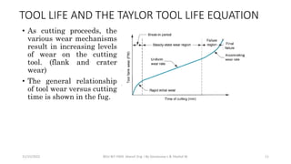
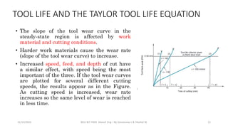
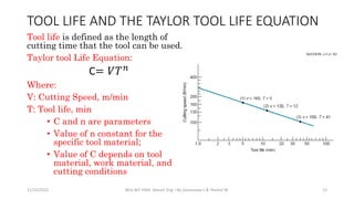
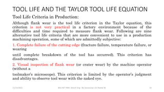
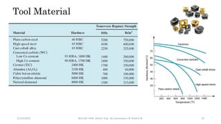
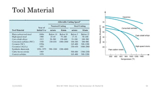
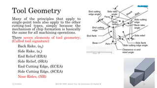
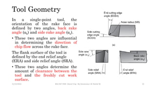
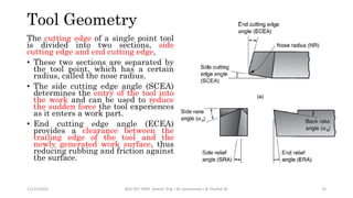
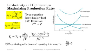
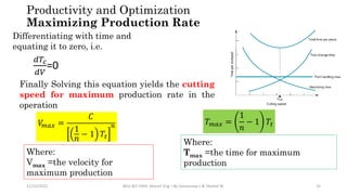
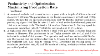
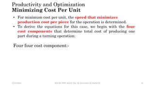
The document discusses traditional machining processes and tooling. It covers topics like turning, milling, and drilling operations; tool motions; tool life and wear; tool materials; tool geometry; machinability; and productivity optimization. Specifically, it describes three modes of tool failure, the factors that influence tool life, tool wear mechanisms, tool material properties, elements of tool geometry, factors that influence machinability, and formulas for optimizing cutting speed for maximum production rate or minimum unit cost.
THE INFLUENCE OF CUTTING SPEED VARIATION IN TURNING OF AISI 304 MATERIALS ON ...IAEME Publication
Tool life is machining data which is related to machining process. The aim of this
research is to determine the tool life, tool wear and Taylor’s tool life equation value of
coated carbide insert when used in turning process of AISI 304 stainless steel. By
completing this research, the tool life of coated carbide insert will be known and can
be estimated when different cutting speed for given feeding speed and depth of cut are
used. The experiment was done by using cutting speed which was varied whereas feed
rate and depth of cut were fixed during the turning process until the tool wear value of
each cutting speed reaches 0.3 mm (VB = 0.3 mm). Taylor’s tool life equation was
obtained as VCTL
0.939=2968 and value of tool life of 29 minutes 10 seconds for low
cutting speed and 15 minutes 36 seconds for high cutting speed
Wear Analysis of Tool in Milling YTL7D SteelIJRES Journal
In the process of milling die steel YTL7D, the properties of high hardness and high wear resistance of
the workpiece material led to that the tool Subjected to severe wear, and the life of the tool is lower. In this
research, the wear law of rake face and flank face of the ball end mill was discussed. And the tool wear
mechanism in the process of milling YTL7D steel is revealed in this paper, to provide a theoretical guidance for
the development of rational process and follow-up studies.
The International Journal of Engineering and Science (The IJES)theijes
The International Journal of Engineering & Science is aimed at providing a platform for researchers, engineers, scientists, or educators to publish their original research results, to exchange new ideas, to disseminate information in innovative designs, engineering experiences and technological skills. It is also the Journal's objective to promote engineering and technology education. All papers submitted to the Journal will be blind peer-reviewed. Only original articles will be published.
HEAP SORT ILLUSTRATED WITH HEAPIFY, BUILD HEAP FOR DYNAMIC ARRAYS.
Heap sort is a comparison-based sorting technique based on Binary Heap data structure. It is similar to the selection sort where we first find the minimum element and place the minimum element at the beginning. Repeat the same process for the remaining elements.
An Approach to Detecting Writing Styles Based on Clustering Techniquesambekarshweta25
An Approach to Detecting Writing Styles Based on Clustering Techniques
Authors:
-Devkinandan Jagtap
-Shweta Ambekar
-Harshit Singh
-Nakul Sharma (Assistant Professor)
Institution:
VIIT Pune, India
Abstract:
This paper proposes a system to differentiate between human-generated and AI-generated texts using stylometric analysis. The system analyzes text files and classifies writing styles by employing various clustering algorithms, such as k-means, k-means++, hierarchical, and DBSCAN. The effectiveness of these algorithms is measured using silhouette scores. The system successfully identifies distinct writing styles within documents, demonstrating its potential for plagiarism detection.
Introduction:
Stylometry, the study of linguistic and structural features in texts, is used for tasks like plagiarism detection, genre separation, and author verification. This paper leverages stylometric analysis to identify different writing styles and improve plagiarism detection methods.
Methodology:
The system includes data collection, preprocessing, feature extraction, dimensional reduction, machine learning models for clustering, and performance comparison using silhouette scores. Feature extraction focuses on lexical features, vocabulary richness, and readability scores. The study uses a small dataset of texts from various authors and employs algorithms like k-means, k-means++, hierarchical clustering, and DBSCAN for clustering.
Results:
Experiments show that the system effectively identifies writing styles, with silhouette scores indicating reasonable to strong clustering when k=2. As the number of clusters increases, the silhouette scores decrease, indicating a drop in accuracy. K-means and k-means++ perform similarly, while hierarchical clustering is less optimized.
Conclusion and Future Work:
The system works well for distinguishing writing styles with two clusters but becomes less accurate as the number of clusters increases. Future research could focus on adding more parameters and optimizing the methodology to improve accuracy with higher cluster values. This system can enhance existing plagiarism detection tools, especially in academic settings.
Hierarchical Digital Twin of a Naval Power SystemKerry Sado
A hierarchical digital twin of a Naval DC power system has been developed and experimentally verified. Similar to other state-of-the-art digital twins, this technology creates a digital replica of the physical system executed in real-time or faster, which can modify hardware controls. However, its advantage stems from distributing computational efforts by utilizing a hierarchical structure composed of lower-level digital twin blocks and a higher-level system digital twin. Each digital twin block is associated with a physical subsystem of the hardware and communicates with a singular system digital twin, which creates a system-level response. By extracting information from each level of the hierarchy, power system controls of the hardware were reconfigured autonomously. This hierarchical digital twin development offers several advantages over other digital twins, particularly in the field of naval power systems. The hierarchical structure allows for greater computational efficiency and scalability while the ability to autonomously reconfigure hardware controls offers increased flexibility and responsiveness. The hierarchical decomposition and models utilized were well aligned with the physical twin, as indicated by the maximum deviations between the developed digital twin hierarchy and the hardware.
Student information management system project report ii.pdfKamal Acharya
Our project explains about the student management. This project mainly explains the various actions related to student details. This project shows some ease in adding, editing and deleting the student details. It also provides a less time consuming process for viewing, adding, editing and deleting the marks of the students.
Industrial Training at Shahjalal Fertilizer Company Limited (SFCL)MdTanvirMahtab2
This presentation is about the working procedure of Shahjalal Fertilizer Company Limited (SFCL). A Govt. owned Company of Bangladesh Chemical Industries Corporation under Ministry of Industries.
Water billing management system project report.pdfKamal Acharya
Our project entitled “Water Billing Management System” aims is to generate Water bill with all the charges and penalty. Manual system that is employed is extremely laborious and quite inadequate. It only makes the process more difficult and hard.
The aim of our project is to develop a system that is meant to partially computerize the work performed in the Water Board like generating monthly Water bill, record of consuming unit of water, store record of the customer and previous unpaid record.
We used HTML/PHP as front end and MYSQL as back end for developing our project. HTML is primarily a visual design environment. We can create a android application by designing the form and that make up the user interface. Adding android application code to the form and the objects such as buttons and text boxes on them and adding any required support code in additional modular.
MySQL is free open source database that facilitates the effective management of the databases by connecting them to the software. It is a stable ,reliable and the powerful solution with the advanced features and advantages which are as follows: Data Security.MySQL is free open source database that facilitates the effective management of the databases by connecting them to the software.
Final project report on grocery store management system..pdfKamal Acharya
In today’s fast-changing business environment, it’s extremely important to be able to respond to client needs in the most effective and timely manner. If your customers wish to see your business online and have instant access to your products or services.
Online Grocery Store is an e-commerce website, which retails various grocery products. This project allows viewing various products available enables registered users to purchase desired products instantly using Paytm, UPI payment processor (Instant Pay) and also can place order by using Cash on Delivery (Pay Later) option. This project provides an easy access to Administrators and Managers to view orders placed using Pay Later and Instant Pay options.
In order to develop an e-commerce website, a number of Technologies must be studied and understood. These include multi-tiered architecture, server and client-side scripting techniques, implementation technologies, programming language (such as PHP, HTML, CSS, JavaScript) and MySQL relational databases. This is a project with the objective to develop a basic website where a consumer is provided with a shopping cart website and also to know about the technologies used to develop such a website.
This document will discuss each of the underlying technologies to create and implement an e- commerce website.
Online aptitude test management system project report.pdfKamal Acharya
The purpose of on-line aptitude test system is to take online test in an efficient manner and no time wasting for checking the paper. The main objective of on-line aptitude test system is to efficiently evaluate the candidate thoroughly through a fully automated system that not only saves lot of time but also gives fast results. For students they give papers according to their convenience and time and there is no need of using extra thing like paper, pen etc. This can be used in educational institutions as well as in corporate world. Can be used anywhere any time as it is a web based application (user Location doesn’t matter). No restriction that examiner has to be present when the candidate takes the test.
Every time when lecturers/professors need to conduct examinations they have to sit down think about the questions and then create a whole new set of questions for each and every exam. In some cases the professor may want to give an open book online exam that is the student can take the exam any time anywhere, but the student might have to answer the questions in a limited time period. The professor may want to change the sequence of questions for every student. The problem that a student has is whenever a date for the exam is declared the student has to take it and there is no way he can take it at some other time. This project will create an interface for the examiner to create and store questions in a repository. It will also create an interface for the student to take examinations at his convenience and the questions and/or exams may be timed. Thereby creating an application which can be used by examiners and examinee’s simultaneously.
Examination System is very useful for Teachers/Professors. As in the teaching profession, you are responsible for writing question papers. In the conventional method, you write the question paper on paper, keep question papers separate from answers and all this information you have to keep in a locker to avoid unauthorized access. Using the Examination System you can create a question paper and everything will be written to a single exam file in encrypted format. You can set the General and Administrator password to avoid unauthorized access to your question paper. Every time you start the examination, the program shuffles all the questions and selects them randomly from the database, which reduces the chances of memorizing the questions.
Online aptitude test management system project report.pdf
Chapter 1P3 -Cutting Tool.pdf
1. Manufacturing Engineering II
Mechanical Engineering 4th year
Chapter 1
11/15/2022
TRADITIONAL MACHINING PROCESSES
BDU-BiT-FMIE Manuf. Eng. I By Gessessew L & Yibeltal W. 1
2. Outline:
• Introduction
• Turning, Milling
and Drilling
processes
Operations
Tool Motions
Time calculation
Material removal
rate
Cutting Tools
• Tool Life and Tool
Wear,
• Tool geometry
• Surface finish
• Machinability
• Productivity and
• optimization
11/15/2022 BDU-BiT-FMIE Manuf. Eng. I By Gessessew L & Yibeltal W.
2
Mechanics of machining
Chip Formation
Forces and Power
Merchant Circle
Cutting Temp.
Cutting Fluid
3. 11/15/2022 BDU-BiT-FMIE Manuf. Eng. I By Gessessew L & Yibeltal W. 3
• Machining operations are accomplished using cutting tools.
• The high forces and temperatures during machining create a very harsh
environment for the tool.
• If cutting force becomes too high, the tool fractures. If cutting temperature
becomes too high, the tool material softens and fails. If neither of these
conditions causes the tool to fail, continual wear of the cutting edge
ultimately leads to failure.
Cutting tool technology has two principal aspects:
1. Tool materials: develops material that withstands the force,
temperature and the wearing action
2. Tool geometry: that optimizes the geometry of the cutting tools for
the tool materials and for a given operation
Cutting Tool
4. There are three possible mode of cutting tool failure in machining:
1. Fracture Failure: mode of failure occurs when cutting force at
the tool point becomes excessive, causing it to failure suddenly
by brittle fracture.
2. Temperature failure: failure occurs when the cutting
temperature is too high for the tool material, causing the
material at the tool point to soften, which leads to plastic
deformation and loss of the sharp edge.
3. Gradual wear: Gradual wearing of the cutting edge causes loss
of tool shape, reduction in cutting efficiency, an acceleration of
wearing as the tool becomes heavily worn, and finally tool
failure in a manner similar to a temperature failure.
11/15/2022 BDU-BiT-FMIE Manuf. Eng. I By Gessessew L & Yibeltal W. 4
Tool life and Tool Wear
5. • Fracture and temperature
failures result in
premature loss of the
cutting tool. These two
modes of failure are
therefore undesirable.
• Gradual wear is preferred
because it leads to the
longest possible use of the
tool, with the associated
economic advantage of
that longer use.
11/15/2022 BDU-BiT-FMIE Manuf. Eng. I By Gessessew L & Yibeltal W. 5
Tool life and Tool Wear
6. Tool Wear
• Gradual wear occurs at two principal
locations on a cutting tool: the top rake
face and the flank.
• Two main types of tool wear can be
distinguished: crater wear and flank
wear,
• Crater wear, consists of a cavity in the
rake face of the tool that forms and
grows from the action of the chip sliding
against the surface. High stresses and
temperatures characterize the tool–chip
contact interface, contributing to the
wearing action. The crater can be
measured either by its depth or its
area.
11/15/2022 BDU-BiT-FMIE Manuf. Eng. I By Gessessew L & Yibeltal W. 6
7. • Flank wear, occurs on the flank, or
relief face, of the tool. It results from
rubbing between the newly
generated work surface and the flank
face adjacent to the cutting edge.
• Flank wear is measured by the width
of the wear band, FW. This wear
band is sometimes called the flank
wear land.
11/15/2022 BDU-BiT-FMIE Manuf. Eng. I By Gessessew L & Yibeltal W. 7
Tool Wear
8. The mechanisms of cutting tool wear (wear at the tool–chip
and tool–work interfaces) /(Gradual wear):
1. Abrasion: This is a mechanical wearing action caused by hard
particles in the work material gouging and removing small portions of
the tool. This abrasive action occurs in both flank wear and crater
wear; it is a significant cause of flank wear.
2. Adhesion: When two metals are forced into contact under high
pressure and temperature, adhesion or welding occur between them.
These conditions are present between the chip and the rake face of
the tool. As the chip flows across the tool, small particles of the tool
are broken away from the surface, resulting in attrition of the
surface.
11/15/2022 BDU-BiT-FMIE Manuf. Eng. I By Gessessew L & Yibeltal W. 8
Tool Wear
9. 3. Diffusion: This is a process in which an exchange of atoms takes place
across a close contact boundary between two materials. In the case of tool
wear, diffusion occurs at the tool–chip boundary, causing the tool surface
to become depleted of the atoms responsible for its hardness. As this
process continues, the tool surface becomes more susceptible to abrasion
and adhesion. Diffusion is believed to be a principal mechanism of crater
wear.
4. Chemical reactions: The high temperatures and clean surfaces at the
tool–chip interface in machining at high speeds can result in chemical
reactions, in particular, oxidation, on the rake face of the tool. The
oxidized layer, being softer than the parent tool material, is sheared
away, exposing new material to sustain the reaction process.
11/15/2022 BDU-BiT-FMIE Manuf. Eng. I By Gessessew L & Yibeltal W. 9
Tool Wear
10. 5. Plastic deformation: It is a plastic deformation of the cutting edge. The
cutting forces acting on the cutting edge at high temperature cause the
edge to deform plastically, making it more vulnerable to abrasion of the
tool surface. Plastic deformation contributes mainly to flank wear.
11/15/2022 BDU-BiT-FMIE Manuf. Eng. I By Gessessew L & Yibeltal W. 10
Tool Wear
11. TOOL LIFE AND THE TAYLOR TOOL LIFE EQUATION
• As cutting proceeds, the
various wear mechanisms
result in increasing levels
of wear on the cutting
tool. (flank and crater
wear)
• The general relationship
of tool wear versus cutting
time is shown in the fug.
11/15/2022 BDU-BiT-FMIE Manuf. Eng. I By Gessessew L & Yibeltal W. 11
12. • The slope of the tool wear curve in the
steady-state region is affected by work
material and cutting conditions.
• Harder work materials cause the wear rate
(slope of the tool wear curve) to increase.
• Increased speed, feed, and depth of cut have
a similar effect, with speed being the most
important of the three. If the tool wear curves
are plotted for several different cutting
speeds, the results appear as in the Figure.
As cutting speed is increased, wear rate
increases so the same level of wear is reached
in less time.
11/15/2022 BDU-BiT-FMIE Manuf. Eng. I By Gessessew L & Yibeltal W. 12
TOOL LIFE AND THE TAYLOR TOOL LIFE EQUATION
13. Tool life is defined as the length of
cutting time that the tool can be used.
Taylor tool Life Equation:
C= 𝑉𝑇𝑛
Where:
V: Cutting Speed, m/min
T: Tool life, min
• C and n are parameters
• Value of n constant for the
specific tool material;
• Value of C depends on tool
material, work material, and
cutting conditions
11/15/2022 BDU-BiT-FMIE Manuf. Eng. I By Gessessew L & Yibeltal W. 13
TOOL LIFE AND THE TAYLOR TOOL LIFE EQUATION
14. Tool Life Criteria in Production:
Although flank wear is the tool life criterion in the Taylor equation, this
criterion is not very practical in a factory environment because of the
difficulties and time required to measure flank wear. Following are nine
alternative tool life criteria that are more convenient to use in a production
machining operation, some of which are admittedly subjective:
1. Complete failure of the cutting edge (fracture failure, temperature failure, or
wearing
until complete breakdown of the tool has occurred). This criterion has
disadvantages.
2. Visual inspection of flank wear (or crater wear) by the machine operator
(without a
toolmaker’s microscope). This criterion is limited by the operator’s judgment
and ability to observe tool wear with the naked eye.
11/15/2022 BDU-BiT-FMIE Manuf. Eng. I By Gessessew L & Yibeltal W. 14
TOOL LIFE AND THE TAYLOR TOOL LIFE EQUATION
15. 3. Fingernail test across the cutting edge by the operator to test for
irregularities.
4. Changes in the sound emitting from the operation, as judged by the
operator.
5. Chips become ribbony, stringy, and difficult to dispose of.
6. Degradation of the surface finish on the work.
7. Increased power consumption in the operation, as measured by a
wattmeter connected to the machine tool.
8. Workpiece count: The operator is instructed to change the tool
after a certain specified number of parts have been machined.
11/15/2022 BDU-BiT-FMIE Manuf. Eng. I By Gessessew L & Yibeltal W. 15
TOOL LIFE AND THE TAYLOR TOOL LIFE EQUATION
16. 9. Cumulative cutting time. This is similar to the previous
workpiece count, except that the length of time the tool has
been cutting is monitored. This is possible on machine tools
controlled by computer; the computer is programmed to keep
data on the total cutting time for each tool.
11/15/2022 BDU-BiT-FMIE Manuf. Eng. I By Gessessew L & Yibeltal W. 16
TOOL LIFE AND THE TAYLOR TOOL LIFE EQUATION
17. Exercises
1. Turning tests have resulted in 1-min tool life at a cutting speed = 4.0 m/s and a 20-
min tool life at a speed = 2.0 m/s. (a) Find the n and C values in the Taylor tool life
equation. (b) Project how long the tool would last at a speed of 1.0 m/s.
2. In a production turning operation, the work part is 125 mm in diameter and 300
mm long. A feed of 0.225 mm/rev is used in the operation. If cutting speed = 3.0 m/s,
the tool must be changed every five work parts; but if cutting speed = 2.0 m/s, the
tool can be used to produce 25 pieces between tool changes. Determine the Taylor
tool life equation for this job.
11/15/2022 BDU-BiT-FMIE Manuf. Eng. I By Gessessew L & Yibeltal W. 17
18. Tool Material
1. Toughness: To avoid fracture failure, the tool material must possess high
toughness. Toughness is the capacity of a material to absorb energy
without failing.
2. Hot hardness: the ability of a material to retain its hardness at high
temperatures. This is required because of the high-temperature
environment in which the tool operates.
3. Wear resistance: Hardness is the single most important property needed
to resist abrasive wear. All cutting-tool materials must be hard. However,
wear resistance in metal cutting depends on more than just tool hardness,
because of the other tool-wear mechanisms.
11/15/2022 BDU-BiT-FMIE Manuf. Eng. I By Gessessew L & Yibeltal W. 18
The three important properties required in a tool materials:
21. Tool Geometry
Many of the principles that apply to
single-point tools also apply to the other
cutting-tool types, simply because the
mechanism of chip formation is basically
the same for all machining operations.
There seven elements of tool geometry;
(Called tool signature)
Back Rake, ( b)
Side Rake, ( s)
End Relief (ERA)
Side Relief, (SRA)
End Cutting Edge, (ECEA)
Side Cutting Edge, (SCEA)
Nose Rides, (NR)
11/15/2022 BDU-BiT-FMIE Manuf. Eng. I By Gessessew L & Yibeltal W. 21
22. In a single-point tool, the
orientation of the rake face is
defined by two angles, back rake
angle ( b) and side rake angle ( s).
• These two angles are influential
in determining the direction of
chip flow across the rake face.
The flank surface of the tool is
defined by the end relief angle
(ERA) and side relief angle (SRA).
• These two angles determine the
amount of clearance between the
tool and the freshly cut work
surface.
Tool Geometry
11/15/2022 BDU-BiT-FMIE Manuf. Eng. I By Gessessew L & Yibeltal W. 22
23. The cutting edge of a single point tool
is divided into two sections, side
cutting edge and end cutting edge,
• These two sections are separated by
the tool point, which has a certain
radius, called the nose radius.
• The side cutting edge angle (SCEA)
determines the entry of the tool into
the work and can be used to reduce
the sudden force the tool experiences
as it enters a work part.
• End cutting edge angle (ECEA)
provides a clearance between the
trailing edge of the tool and the
newly generated work surface, thus
reducing rubbing and friction against
the surface.
Tool Geometry
11/15/2022 BDU-BiT-FMIE Manuf. Eng. I By Gessessew L & Yibeltal W. 23
24. Machinability
Machinability denotes the relative ease with which a
material (usually a metal) can be machined using appropriate
tooling and cutting conditions.
There are various criteria used to evaluate machinability, the
most important of which are:
1. Tool life,
2. Forces and power,
3. Surface finish, and
4. Ease of chip disposal
11/15/2022 BDU-BiT-FMIE Manuf. Eng. I By Gessessew L & Yibeltal W. 24
25. Productivity and Optimization
11/15/2022 BDU-BiT-FMIE Manuf. Eng. I By Gessessew L & Yibeltal W. 25
• Selection of cutting speed is based on making the best use of the cutting
tool, which normally means choosing a speed that provides a high metal
removal rate yet suitably long tool life.
• Mathematical formulas have been derived to determine optimal
cutting speed for a machining operation, given that the various time and
cost components of the operation are known.
26. Productivity and Optimization
11/15/2022 BDU-BiT-FMIE Manuf. Eng. I By Gessessew L & Yibeltal W. 26
• The formulas allow the optimal cutting speed to be calculated for
either of two objectives:
1. Maximum production rate, or
2. Minimum unit cost.
• The formulas are based on a known Taylor tool life
equation for the tool used in the operation.
• Accordingly, feed, depth of cut, and work material
have already been set.
• The derivation will be illustrated for a turning operation.
27. Productivity and Optimization
Maximizing Production Rate
11/15/2022 BDU-BiT-FMIE Manuf. Eng. I By Gessessew L & Yibeltal W. 27
• For maximum production rate, the speed that
minimizes machining time per workpiece is determined.
• Minimizing cutting time per unit is equivalent to
maximizing production rate.
• This objective is important in cases when the
production order must be completed as quickly as
possible.
• In turning, there are three time elements that contribute
to the total production cycle time for one part:
28. 11/15/2022 BDU-BiT-FMIE Manuf. Eng. I By Gessessew L & Yibeltal W. 28
Three time elements:
1. Part handling time Th: the time the operator spends loading the
part into the machine tool at the beginning of the production cycle and
unloading the part after machining is completed. Any additional time
required to reposition the tool for the start of the next cycle should also be
included here.
2. Machining time Tm: the time the tool is actually engaged in
machining during the cycle.
3. Tool change time Tt:At the end of the tool life, the
tool must be changed, which takes time. This time must be divided over
the number of parts cut during the tool life. Let np=the number of pieces cut
in one tool life (the number of pieces cut with one cutting edge until the tool
is changed); thus, the tool change time per part=Tt/np
Productivity and Optimization
Maximizing Production Rate
29. 11/15/2022 BDU-BiT-FMIE Manuf. Eng. I By Gessessew L & Yibeltal W. 29
The sum of these three time elements gives the total time per unit
product for the operation cycle
𝑇𝑐 = 𝑇ℎ + 𝑇𝑚 +
𝑇𝑡
𝑛𝑝
Where: Tc-Total
cycle time per piece
The cycle time Tc is a function of cutting
speed. As cutting speed is increased, Tm
decreases and Tt/np increases; Th is
unaffected by speed. These relationships
are shown in Figure.
Productivity and Optimization
Maximizing Production Rate
30. 11/15/2022 BDU-BiT-FMIE Manuf. Eng. I By Gessessew L & Yibeltal W. 30
𝑇𝑚 =
𝜋𝐷𝐿
𝑉𝑓
Where:
Tm=|Machine Time, min
D=Work diameter, mm
L=Work length, mm
V=Cutting velocity,
mm/min
F=Feed, mm/rev
The number of pieces per tool
np is also a function of speed.
It can be shown that
𝑛𝑝 =
𝑇
𝑇𝑚
Where:
np=No. of pieces machined
Tm=Machine Time, min
T=Tool Life, min
Productivity and Optimization
Maximizing Production Rate
31. 11/15/2022 BDU-BiT-FMIE Manuf. Eng. I By Gessessew L & Yibeltal W. 31
𝑛𝑝 =
(𝐶
𝑉)1/𝑛
(𝜋𝐷𝐿
𝑓𝑉)
Type equation
here.Taylor Tool
Life Equation;
𝑉𝑇𝑛
= 𝐶
𝑛𝑝 =
𝑓𝐶1/𝑛
𝜋𝐷𝐿𝑉
1
𝑛
−1
𝑇𝑐 = 𝑇ℎ +
𝜋𝐷𝐿
𝑓𝑉
+
𝑇𝑡(𝜋𝐷𝐿𝑉
1
𝑛
−1
)
𝑓𝐶1/𝑛
Differentiating with time and equating it to zero, i.e.
𝑑𝑇𝑐
𝑑𝑉
=0
Productivity and Optimization
Maximizing Production Rate
32. 11/15/2022 BDU-BiT-FMIE Manuf. Eng. I By Gessessew L & Yibeltal W. 32
Differentiating with time and
equating it to zero, i.e.
𝑑𝑇𝑐
𝑑𝑉
=0
Finally Solving this equation yields the cutting
speed for maximum production rate in the
operation
𝑉
𝑚𝑎𝑥 =
𝐶
1
𝑛
− 1 𝑇𝑡
𝑛
Where:
Vmax =the velocity for
maximum production
𝑇𝑚𝑎𝑥 =
1
𝑛
− 1 𝑇𝑡
Where:
Tmax =the time for maximum
production
Productivity and Optimization
Maximizing Production Rate
33. 11/15/2022 BDU-BiT-FMIE Manuf. Eng. I By Gessessew L & Yibeltal W. 33
Productivity and Optimization
Maximizing Production Rate
Problems:
1. A cemented carbide tool is used to turn a part with a length of 400 mm in and
diameter = 100 mm. The parameters in the Taylor equation are: n=0.25 and C=305
m/min. The rate for the operator and machine tool =45 Birr/hr, and the tooling cost
per cutting edge = 2.50 Birr. It takes 2.5 min to load and unload the work part and
1.50 min to change tools. The feed = 0.4 mm/rev. Determine A. Cutting speed for
maximum production rate, B. Tool life for max prod, and C. Cycle time.
2. A high-speed steel tool is used to turn a steel work part that is 300mm long and
80mm in diameter. The parameters in the Taylor equation are: n=0.13 and C=75
(m/min) for a feed of 0.4 mm/rev. The operator and machine tool rate=30 Birr/hr,
and the tooling cost per cutting edge=Birr 4. It takes 2.0 min to load and unload
the workpart and 3.50 min to change tools. Determine (a) cutting speed for
maximum production rate, (b) tool life in min of cutting, and (c) cycle time and cost
per unit of product.
Note: Your Calculations should be in two decimal places.
34. 11/15/2022 BDU-BiT-FMIE Manuf. Eng. I By Gessessew L & Yibeltal W. 34
Productivity and Optimization
Minimizing Cost Per Unit
• For minimum cost per unit, the speed that minimizes
production cost per piece for the operation is determined.
• To derive the equations for this case, we begin with the four
cost components that determine total cost of producing one
part during a turning operation:
Four four cost component:-
35. 11/15/2022 BDU-BiT-FMIE Manuf. Eng. I By Gessessew L & Yibeltal W. 35
Productivity and Optimization, Minimizing Cost Per Piece
2. Cost of machining time: the cost of the time the tool is engaged in
machining. Using Co again to represent the cost per minute of the
operator and machine tool, the cutting time cost = CoTm.
3. Cost of tool change time: The cost of tool change time = CoTt/np.
4. Tooling cost: In addition to the tool change time, the tool itself has a cost
that must be added to the total operation cost. This cost is the cost per
cutting edge Ct, divided by the number of pieces machined with that
cutting edge np. Thus, tool cost per work piece is given by Ct/np.
1. Cost of part handling time: This is the cost of the time the operator
spends loading and unloading the part. Let Co= the cost rate (e.g.,
Birr/min) for the operator and machine. Thus the cost of part handling
time = CoTh.
36. 11/15/2022 BDU-BiT-FMIE Manuf. Eng. I By Gessessew L & Yibeltal W. 36
Productivity and Optimization
Minimizing Cost Per Unit
Total Cost per unit product, Cc
𝐶𝑐 = 𝐶𝑜𝑇ℎ + 𝐶𝑜𝑇𝑚 +
𝐶𝑜𝑇𝑡
𝑛𝑝
+
𝐶𝑡
𝑛𝑝
Cc is function of cutting speed V
𝐶𝑐 = 𝐶𝑜𝑇ℎ + 𝐶𝑜
𝜋𝐷𝐿
𝑓𝑣
+
(𝐶𝑜𝑇𝑡 + 𝐶𝑡)(𝜋𝐷𝐿𝑉
1
𝑛
−1
𝑓𝐶1/𝑛
37. 11/15/2022 BDU-BiT-FMIE Manuf. Eng. I By Gessessew L & Yibeltal W. 37
Productivity and Optimization; Minimizing Cost Per Unit
The cutting speed that obtains minimum cost per piece for the operation
can be determined by taking the derivative of Cc with respect to V , setting
it to zero, and solving for Vmin
𝑑𝐶𝑐
𝑑𝑉
= 0 𝑉𝑚𝑖𝑛 = 𝐶(
𝑛
1 − 𝑛
∗
𝐶𝑜
𝐶𝑜𝑇𝑡 + 𝐶𝑡
)𝑛
Vmin= Velocity for minimum cost per piece
𝑇𝑚𝑖𝑛 = (
1
𝑛
− 1)(
𝐶𝑜𝑇𝑡 + 𝐶𝑡
𝐶𝑜
)
38. 1. A high-speed steel tool is used to turn a steel work part that is
300mmlong and 80mm in diameter. The parameters in the Taylor
equation are: n = 0.13 and C =75 (m/min) for a feed of 0.4 mm/rev.
The operator and machine tool rate = 50 Birr/hr, and the tooling
cost per cutting edge=Birr 25. It takes 2.0 min to load and unload
the work part and 3.50 min to change tools. Determine: A. Cutting
speed for minimum cost, B. Tool life for minimum cost, and C. Unit
cost per piece.
2. The tool change time = 3.0 min. The tooling cost is paid at a rate of
20 Birr/hr. Machine and operator cost of the lathe=24 Birr /hr. The
feed = 0.30 mm/rev. The parameters in the Taylor equation for this
grade are: n=0.25 and C=300 (m/min). Determine: A. Cutting for
minimum cost per piece, B. Tool life for minimum cost, C. Cost per
piece, D. Cutting speed for maximum production.
11/15/2022 BDU-BiT-FMIE Manuf. Eng. I By Gessessew L & Yibeltal W. 38
Productivity and Optimization
Minimizing Cost Per Unit
Note: Your Calculations should be in two decimal places.