The document provides specifications for various models of the 3/4-ton 4x4 Dodge truck, including:
- It describes the basic configuration of the truck and differences between models.
- Tabulated data includes details on the engine, transmission, electrical systems, dimensions, weights, performance specifications, and capacities of the different truck models.
- Models covered are the weapon carrier, command, carryall, ambulance, telephone maintenance, and emergency repair vehicles. Specifications cover areas like engine/transmission configuration, electrical systems, dimensions, weights, speeds, grades, and more.


![WAR DEPARTMENT
Washington 25, D. C., 31 January 1944
TM 9-808, 3/4-ton 4 x 4 Truck (Dodge), is published
for the information and guidance of all concerned
[A.G. 300.7 (20 Oct. 43)]
BY ORDER OF THE SECRETARY OF WAR:
G. C. MARSHALL,
Chief of Staff.
OFFCIAL: -
- cA. FIO' _Ioi
M or.:Gezeral,
The XdjutanhFneral.
Disi~r TxoN: B and H-S); B18 (2); R9 (4); Bn 6, 7, 9 and 18
""'--- (2) ; :C',7and 18 (2), 9 (5).
(For &xplanation of symbols, see FM 21-6)
2](https://image.slidesharecdn.com/tm9-808-140814010618-phpapp01/85/Dodge-3-4-TM-9-808-3-320.jpg)


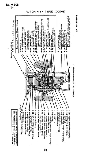
![TM 9-808
24
LUBRICATION
ul
C4
~' o ~ of.-. r. Q~Z .u
co
t
~
~o od
?· o . MS,,.- ' ! < _ E _
u.:' es IC
°
·.o emu 6 2 _
'a
<_32ibsseEo--i>_ul]g ~II 5H
aoor _ o - o 3§ 0
+ l_
X i~~~~ C',
~~~~~~~ulF~~~~~~~~~~~~~~~~~~~~u
.....' ... . ,... 1 ~-
- I - - OS-,.,A
if .~~ '~rJl (
It, e-- ..<-o t '(---- '
WI=~
- II.,-wM-- O..-__....Ii
~~~9jl II o.. ozdo~,o/'
ala
I. I,
i__L° ~o-=--j :3t3 XwL
59](https://image.slidesharecdn.com/tm9-808-140814010618-phpapp01/85/Dodge-3-4-TM-9-808-60-320.jpg)


![[English Version]Maker-Ray Product Brochure V3 .pdf](https://cdn.slidesharecdn.com/ss_thumbnails/englishversionmaker-rayproductbrochurev3-260113094444-0156dbdc-thumbnail.jpg?width=640&height=640&fit=bounds)


