SlideShare a Scribd company logo
1 of 26
Download to read offline
GP/GLP/GDP040-060RG/TG/ZG (A875)
SERVICE MANUAL CONTENTS
SECTION
PART
NUMBER
YRM
NUMBER
REV
DATE
FRAME............................................................................................................................ 524158636 0100 YRM 0505 06/04
MAZDA FE AND F2 ENGINE......................................................................................... 524158742 0600 YRM 0496 01/11
MAZDA HA/XA DIESEL ENGINES................................................................................ 524162461 0600 YRM 1019 01/11
GM 3.0L GAS/LPG ENGINE........................................................................................... 524158637 0600 YRM 1020 10/06
COOLING SYSTEM........................................................................................................ 524150775 0700 YRM 0626 03/03
LPG FUEL SYSTEM (GM 3.0L)...................................................................................... 524158744 0900 YRM 0498 12/03
GASOLINE FUEL SYSTEM (MAZDA)........................................................................... 524158745 0900 YRM 0502 12/03
LPG FUEL SYSTEM (MAZDA)....................................................................................... 524158746 0900 YRM 0523 12/03
LPG FUEL SYSTEM (AISAN OPEN LOOP).................................................................. 524158747 0900 YRM 0925 12/03
LPG FUEL SYSTEM (AISAN CLOSED LOOP)............................................................. 524158748 0900 YRM 0948 10/06
ELEC. CONT. LPG/GAS FUEL SYS GM 3.0/4.3L EPA COMP. ENG........................... 524208004 0900 YRM 1088 05/06
GASOLINE FUEL SYS MAZDA FE AND FE EPA COMP. ENG................................... 524214124 0900 YRM 1089 04/04
SINGLE-SPEED POWERSHIFT TRANSMISSION-DESC AND OPER......................... 524158749 1300 YRM 0500 08/03
SINGLE-SPEED POWERSHIFT TRANSMISSION-REPAIR.......................................... 524158750 1300 YRM 0501 03/04
DRIVE AXLE................................................................................................................... 524158751 1400 YRM 0499 10/04
STEERING AXLE............................................................................................................ 524158752 1600 YRM 0316 08/06
STEERING CONTROL UNIT.......................................................................................... 524158753 1600 YRM 0720 11/06
BRAKE SYSTEM............................................................................................................ 524158754 1800 YRM 0506 05/05
HYDRAULIC SYSTEM, GEAR PUMP ASSEMBLY....................................................... 524158755 1900 YRM 0513 06/04
MAIN CONTROL VALVE................................................................................................ 524158756 2000 YRM 0516 12/03
TILT CYLINDERS........................................................................................................... 524150790 2100 YRM 0103 03/07
ALTERNATOR................................................................................................................ 524150791 2200 YRM 0002 12/04
STARTER........................................................................................................................ 524150792 2200 YRM 0106 12/04
HIGH ENERGY IGNITION (HEI) SYSTEM..................................................................... 524153914 2200 YRM 0107 03/08
INSTRUMENT CLUSTER............................................................................................... 524158757 2200 YRM 0514 01/04
ELECTRICAL SYSTEM (MAZDA FE AND F2 ENGINES)............................................. 524158758 2200 YRM 0524 12/03
MICROPROCESSOR SPARK TIMING SYSTEM (GM 3.0L) (EARLY MODELS)......... 524158759 2200 YRM 0603 12/03
EEC-TROUBLESHOOTING AND REPAIR (GM 3.0L)................................................... 524158885 2200 YRM 0611 12/03
EEC - DESCRIPTION AND OPERATION...................................................................... 524158887 2200 YRM 0612 12/03
MICROPROCESSOR SPARK TIMING SYSTEM (GM 3.0L/4.3L) (LATER MODELS). 524153916 2200 YRM 0765 03/03
EEC-DESCRIPTION AND OPERATION (GM 3.0L/4.3L)............................................... 524153917 2200 YRM 0781 03/03
EEC-TROUBLESHOOTING AND REPAIR.................................................................... 524153918 2200 YRM 0782 03/03
ECM DESCRIPTION AND OPERATION (MEFI)............................................................ 524162462 2200 YRM 1016 10/04
ECM TROUBLESHOOTING AND REPAIR (MEFI)........................................................ 524162463 2200 YRM 1017 10/04
ECM DIAG. TROUBLESHOOTING GM 3.0L/4.3L EPA COMP. ENG........................... 524208009 2200 YRM 1090 04/05
ECM DIAGNOSTIC TROUBLESHOOTING (MAZDA FE AND F2)................................ 524217573 2200 YRM 1092 04/05
ELECTRICAL SYSTEM MAZDA FE AND F2 GAS EPA COMP. ENG.......................... 524214123 2200 YRM 1104 03/04
MAST - DESCRIPTION................................................................................................... 524158890 4000 YRM 0521 03/06
MAST - REPAIR.............................................................................................................. 524158891 4000 YRM 0522 07/10
METRIC AND INCH (SAE) FASTENERS....................................................................... 524150797 8000 YRM 0231 10/13
PERIODIC MAINTENANCE............................................................................................ 524158900 8000 YRM 0707 06/09
CAPACITIES AND SPECIFICATIONS........................................................................... 524158901 8000 YRM 0708 01/11
DIAGRAMS..................................................................................................................... 524158902 8000 YRM 0709 10/04
Service information for Cummins diesel engines can be ordered through the Hyster Literature Distribution Center.
PART NO. 524158635 (10/13)
100 YRM 505 Operator Module Repair
General
WARNING
The lift truck must be put on blocks for some types
of maintenance and repair. The removal of the
following assemblies will cause large changes in
the center of gravity: mast, drive axle, engine and
transmission, and counterweight. When the lift
truck is put on blocks, put additional blocks in the
following positions to maintain stability:
• Before removing the mast and drive axle, put
blocks under the counterweight so the lift truck
cannot fall backward.
• Before removing the counterweight, put blocks
under the mast assembly so the lift truck cannot
fall forward.
The surface must be solid, even, and level when the
lift truck is put on blocks. Make sure that any blocks
used to support the lift truck are solid, one-piece
units. See the Operating Manual or the Periodic
Maintenance manual for your lift truck.
This section has the description of the frame and some
connected parts. See Figure 1. Procedures for the re-
moval and installation of the counterweight, hood, over-
head guard, and engine (including the transmission) are
found in this section. Checks for the operator restraint
system and procedures for the repair of fuel and hy-
draulic tanks and installation of safety labels are also
included.
Description
The frame is one weldment and includes the hydraulic
tank and the fuel tank for gasoline or diesel fuel. There
is a counterweight for each capacity of lift truck. The
counterweights are similar, but are different weights.
The muffler is fastened to the frame inside of the coun-
terweight.
An operator module is installed on the frame with rubber
mounts. See Figure 1. The overhead guard, steering
controls, instrument panel, hood, and seat are installed
on the operator module. The hood is connected to the
operator module with hinges. The floor plates and side
access doors can be removed for access to the engine,
transmission, and other components.
Operator Module Repair
REMOVE
1. Remove the hood and side covers. See Figure 2.
2. Remove the steering housing and instrument clus-
ter from the cowl. Remove the capscrews that hold
the parking brake lever to the cowl.
3. Remove the nuts and bolts at the mounts for the
operator module.
4. Connect a lifting device to the overhead guard. The
overhead guard and module weigh approximately
385 kg (850 lb). Lift the operator module from the
frame.
INSTALL
NOTE: If the overhead guard was removed from the
operator module, tighten the rear leg mount capscrews
to 53 N•m (39 lbf ft). On GP2.00-3.00TF/RF (GP040-
060RG/TG/ZG) units, tighten the capscrews that fasten
the module cowl side plate to the front legs to 66 N•m
(49 lbf ft). See Figure 1.
1. Connect a lifting device to the overhead guard. The
overhead guard and module weigh approximately
385 kg (850 lb). Lift the operator module onto the
frame.
2. Make sure the rubber mounts are installed in the
frame. Install the large washer and nut on the bot-
tom of the mount. Tighten the nuts to 53 N•m
(39 lbf ft).
3. Install the hood and side covers.
4. Install the steering controls and the parking brake
lever.
5. Install the floor plates.
1
Operator Module Repair 100 YRM 505
Figure 1. Frame and Operator Module
2
100 YRM 505 Hood and Side Covers Repair
Legend for Figure 1
1. OPERATOR MODULE
2. FRAME
3. HYDRAULIC TANK
4. STEERING AXLE MOUNT
5. DRIVE AXLE MOUNT
6. CAPSCREW
7. WASHER
8. RUBBER MOUNT
9. NUT
10. COVER
11. STORAGE COMPARTMENT
12. OVERHEAD GUARD (RAISED)
13. SCREW
14. HANDLE
15. PLUG
16. LOCKWASHER
17. BAR
18. FENDER
19. CROSSMEMBER
Hood and Side Covers Repair
WARNING
The hood and hood latch must be correctly adjusted
for the correct operation of the operator restraint
system.
The operator’s seat is fastened to the upper hood
panel. This upper hood panel opens forward for access
to the engine compartment. Two hinges fasten the
upper hood panel to the front plate weldment of the
engine compartment. A latch mechanism with a push
knob holds the upper hood panel in position during
operation of the lift truck. See Figure 2.
A torsion spring is fastened between the front plate
weldment and the upper hood panel to help personnel
when opening and closing the hood. Sound-absorbing
materials are fastened inside the hood panels to reduce
noise during operation. See Figure 2 and Figure 3.
REMOVE
Remove the floor plate and the hood and side covers.
INSTALL AND ADJUST
Install and adjust the hood and side covers as follows:
1. Install the crossmember onto the frame. Install the
front plate weldment, but do not tighten the four
capscrews.
2. Install the hinges on the upper hood panel. Do not
tighten the capscrews.
3. Install the latch hook.
4. Install the upper hood panel in position on the front
plate weldment. Connect the torsion spring. Install
the hinge pins. Install the rod.
5. Close the upper hood panel until the rubber cush-
ions are against the rear crossmember of the en-
gine compartment. Align the edge of the upper
hood panel with the rear crossmember of the en-
gine compartment. Tighten the capscrews for the
hinges.
6. When the upper hood panel is fully closed, check
that the latch fully engages the latch hook. If the
latch does not engage correctly, add or remove
washers (shims) as necessary to adjust the latch
assembly. When the adjustment is correct, tighten
the capscrews that hold the latch assembly.
7. Install the hinges onto the engine compartment, but
do not tighten the bolts.
8. Install the access doors on the hinges. Close the
access doors. Adjust the stop bolts and front plate
so that the front plate is even from side to side and
the access doors will engage the tabs. Tighten the
capscrews on the front plate. Tighten the jam nuts
on the stop bolts.
9. Adjust the hinges so that the front edges of the ac-
cess doors are even with the front plate. Tighten
the bolts for the hinges. Install washers (shims) as
necessary so that the access doors are against the
hood seal when they are closed.
3
Hood and Side Covers Repair 100 YRM 505
1. ACCESS DOOR (LH)
2. ACCESS DOOR (RH)
3. CROSSMEMBER
4. UPPER HOOD PANEL
5. PLATE
6. HINGE
7. ROD
8. TORSION SPRING
9. LATCH HOOK
10. SPACER
11. BUSHING
12. RUBBER CUSHION
13. TRIM
14. CAPSCREW
15. NUT
16. WASHER
17. PIN
18. COTTER PIN
19. SEAL
20. LATCH ASSEMBLY
Figure 2. Hood and Side Covers Arrangement
4
100 YRM 505 Overhead Guard Repair
1. LATCH ASSEMBLY
2. PUSH KNOB
3. LATCH HOOK
4. LATCH (ENGAGED)
5. LATCH (DISENGAGED)
6. SHIMS (AS NECESSARY)
7. UPPER HOOD PANEL
8. FRONT PLATE
9. REAR CROSSMEMBER OF ENGINE
COMPARTMENT
10. TORSION SPRING
11. STOP BOLT
12. FRONT CROSSMEMBER OF ENGINE
COMPARTMENT
Figure 3. Hood Assembly
Overhead Guard Repair
REMOVE AND INSTALL
WARNING
Do not operate the lift truck without the overhead
guard correctly fastened to the lift truck.
Changes that are made by welding, or by drilling
holes that are too big or in the wrong location, can
reduce the strength of the overhead guard. See the
section Changes to the Overhead Guard in the Peri-
odic Maintenance 8000 YRM 707 for instructions on
making changes to the overhead guard.
1. Connect a crane or lifting device to remove or install
the overhead guard. Disconnect the air intake at the
overhead guard leg.
5
Overhead Guard Repair 100 YRM 505
2. Disconnect any wires between the frame and the
overhead guard. When the overhead guard is lifted
from the frame, make sure that any electrical wires
are moved through the holes in the frame so that
they are not damaged.
3. There are two capscrews at each corner of the left-
hand leg of the overhead guard. Remove and install
the capscrews for the overhead guard as follows:
a. Access to the bolts at the front of the overhead
guard is under the dash panel. Remove the
plastic box from the right-hand side of the dash
panel.
b. Access to the bolts at the rear of the overhead
guard is under the rear fender wells.
c. Tighten the rear leg mount capscrews to
53 N•m (39 lbf ft). On GP2.00-3.00TF/RF
(GP040-060RG/TG/ZG) units, tighten the cap-
screws that fasten the module cowl side plate
to the front legs to 66 N•m (49 lbf ft).
NOTE: The air inlet for the air filter is installed in the
left-hand leg of the overhead guard. Make sure the grill
is installed with the louvers pointed downward.
LED BACKUP AND BRAKE LIGHTS,
REPLACE
NOTE: Newer models of lift trucks are equipped with
LED (Light Emitting Diode) backup and brake tail lights.
These light assemblies are non-repairable and must be
replaced as a complete unit. See the Parts Manual for
replacement LED lights.
Remove
1. Disconnect negative terminal of battery and remove
the key.
2. Disconnect the LED light from the chassis light har-
ness.
3. Remove LED light assembly and harness from
mounting bracket. See Figure 4.
4. If the LED mounting bracket must be removed from
the overhead guard leg, remove the plug, screw
and bracket from the overhead guard leg.
Install
1. If the mounting bracket was removed, install it onto
the overhead guard leg. Insert the plug and screw
to attach mounting bracket to overhead guard leg.
See Figure 4.
2. Install the LED light assembly and harness on the
mounting bracket.
3. Connect the LED light to the chassis light harness.
4. Connect the negative terminal of battery and close
the hood.
A. LED ASSEMBLY WITH STANDARD EXHAUST
B. LED ASSEMBLY WITH OVERHEAD EXHAUST
1. LED LIGHT
2. SCREW
3. WASHER
4. LOCKNUT
5. MOUNTING BRACKET
6. GROMMET
7. PLUG
8. SCREW
9. OVERHEAD GUARD LEG
Figure 4. LED Backup and Brake Lights Assembly
6
100 YRM 505 Counterweight Repair
Counterweight Repair
WARNING
The lift truck must be put on blocks for some types
of maintenance and repair. The removal of the
following assemblies will cause large changes in
the center of gravity: mast, drive axle, engine and
transmission, and counterweight. When the lift
truck is put on blocks, put additional blocks in the
following positions to maintain stability:
• Before removing the mast and drive axle, put
blocks under the counterweight so the lift truck
cannot fall backward.
• Before removing the counterweight, put blocks
under the mast assembly so the lift truck cannot
fall forward.
The surface must be solid, even, and level when
the lift truck is put on blocks. Make sure that any
blocks used to support the lift truck are solid, one-
piece units. See the Operating Manual or Periodic
Maintenance 8000 YRM 707 for your lift truck.
The counterweight is held in position on the frame by
two hooks that are part of the frame. One M24 × 3
capscrew holds the counterweight to the lower part of
the frame.
REMOVE
WARNING
Do not operate the lift truck if the capscrew for the
counterweight is not installed. When the capscrew
is removed, the counterweight can fall from the lift
truck.
WARNING
LPG can cause an explosion. Do not cause sparks
or permit flammable material near the LPG system.
LPG fuel systems can be disconnected indoors
only if the lift truck is at least 8 m (26 ft) from any
open flame, motor vehicles, electrical equipment,
or ignition source.
Close the shutoff valve on the LPG tank before any
part of the engine fuel system is disconnected. Run
the engine until the fuel in the system is used and
the engine stops.
If the engine will not run, close the shutoff valve on
the LPG tank. Loosen the fitting on the supply hose
from the LPG tank where it enters the filter unit.
Permit the pressure in the fuel system to decrease
slowly. Fuel leaving the fitting removes heat. Use a
cloth to protect your hands from the cold fitting.
1. If the lift truck has an LPG fuel system, use the
following procedure to remove the LPG tank and
bracket so that the counterweight can be removed.
See Figure 5.
Additional information on the LPG fuel system can
be found in the following sections:LPG Fuel Sys-
tem, GM 2.2L and 3.0L Engines 900 YRM 498,
LPG Fuel System, Mazda FE Engine 900 YRM
523, or Electronic Controlled LPG/Gasoline Fuel
System, GM 3.0L and 4.3L EPA Compliant En-
gines 900 YRM 1088.
a. LPG tanks can be removed and replaced in-
doors only if the lift truck is at least 8 m (26 ft)
from any flame or ignition source.
b. Move the lift truck to the area where tanks are
changed.
c. Turn the shutoff valve clockwise until the valve
is completely closed.
d. Run the engine until it stops, then turn the key
switch to the OFF position.
e. Disconnect the quick-disconnect fitting.
f. Release the LPG tank latch and remove the
tank from the bracket.
2. If an overhead exhaust is installed, remove it as
shown in Figure 12.
WARNING
The counterweight is heavy. Make sure that the eye-
bolt and lifting devices have enough capacity to lift
the weight. The approximate weights of the coun-
terweight castings are shown in Table 1.
3. Install a lifting eye in the lifting hole of the counter-
weight. See Figure 5. Connect a crane to the lift-
ing eye and raise the crane until it holds part of the
weight of the counterweight. Remove the capscrew
that holds the counterweight to the frame. Use the
crane to lift the counterweight from the lift truck. Put
the counterweight on the floor so that it has stability
and will not fall over. Remove the spacers from the
mounts.
7
Counterweight Repair 100 YRM 505
1. COUNTERWEIGHT
2. CAPSCREW (M24
× 3 × 180)
3. LOCKWASHER
4. WASHER
5. TOW PIN
6. ROLL PIN
7. SEAL
8. SHIM
9. NUT
10. CAP
11. LIFTING HOLE
Figure 5. Counterweight
Table 1. Weight of Counterweights
Model kg lbs
GP 040 1,080 ±16 2380 ±35
GP 050 1406 ±21 3100 ±46
GP 060 1800 ±27 3970 ±60
GC 040 1070 ±15 2360 ±33
GC 050 1433 ±21 3160 ±46
GC 060 1855 ±28 4090 ±62
INSTALL
1. Install the spacers on the mounts. See Figure 6.
Use a crane to install the counterweight on the lift
truck. When the counterweight is installed, make
sure the hooks on the frame fully engage the coun-
terweight so it is aligned with the parts of the frame.
Use the spacers to obtain a gap of 8.5 to 11.5 mm
(0.33 to 0.45 in.) between the counterweight and
the overhead guard leg. Install and tighten the M24
× 3 capscrew to 555 N•m (409 lbf ft).
2. If the lift truck has an LPG fuel system, use the
following procedure to install the bracket and LPG
tank after the counterweight has been installed:
a. Before the LPG tank is installed on the lift truck,
make sure the tank has fuel in it. Check the
operation of the fuel gauge. Look at the fuel
gauge and move the tank. If the gauge needle
does not move, a new tank must be installed.
b. Put the tank in the tank bracket. Make sure the
tank is aligned with the alignment pin.
c. Close the latch.
d. Connect the quick-disconnect fitting to the shut-
off valve on the tank. Use your hand to tighten
the fitting. Do not open the shutoff valve until
the quick-disconnect fitting is completely tight-
ened. Turn the shutoff valve counterclockwise
to open the valve.
e. Inspect the fuel system for leaks when the shut-
off valve is open. Frost on the surface of the
tank, valves, or fittings or a strong odor indi-
cates leakage.
3. If the lift truck has an overhead exhaust, install it as
shown in Figure 12.
8
100 YRM 505 Exhaust System Repair
Figure 6. Counterweight Installation
Legend for Figure 6
1. SPACER
2. RUBBER SEAL
3. CAPSCREW
Exhaust System Repair
The muffler is installed inside the cavity of the counter-
weight. A short exhaust pipe sends the exhaust gases
from the lift truck through the grille in the counterweight.
See Figure 7, Figure 8, Figure 9 or Figure 10.
An optional catalytic converter can be installed in the
exhaust system between the engine and the muffler.
See Figure 11. The type of catalytic converter installed
depends on the fuel the engine uses. See the Parts
Manual for your lift truck model.
The GP2.00-3.00RF/TF (GP040-060RG/TG/ZG) series
of lift trucks can have an overhead exhaust system. The
exhaust pipe is fastened to the top of the counterweight.
See Figure 12.
9
Exhaust System Repair 100 YRM 505
MUFFLER, REPLACE
The counterweight must be removed to repair or install
a new muffler or other parts of the exhaust system. See
Figure 7. When connecting the exhaust pipe to the en-
gine, do the following:
1. Install the adapter on the exhaust manifold. Tighten
the nuts for the adapter to 40 N•m (30 lbf ft). Install
the exhaust seal, spacer, and exhaust pipe. In-
stall the springs and special capscrews. Tighten
the special capscrews to 38 N•m (28 lbf ft).
2. On units with an overhead exhaust, tighten the cap-
screws that hold the overhead exhaust to the coun-
terweight to 38 N•m (28 lbf ft). Install the cover.
1. MUFFLER
2. CLAMP
3. CAPSCREW
4. NUT
5. WASHER
6. SPACER
7. PIPE
8. TUBE
9. SEAL
10. SPRING
11. LOCKWASHER
12. GASKET
13. ADAPTER
Figure 7. Exhaust System (Gasoline and LPG)
10
100 YRM 505 Exhaust System Repair
1. MUFFLER
2. COUNTERWEIGHT EXHAUST PIPE
3. GASKET
4. EXHAUST PIPE
5. SEAL
6. SPRING
7. SPECIAL SCREW
8. OXYGEN SENSOR PORT
9. RAW GAS CHECK PORT
Figure 8. Exhaust System, GM3.0L EPA Compliant
11
Exhaust System Repair 100 YRM 505
1. MUFFLER
2. SPACER
3. BRACKET
4. CATALYTIC CONVERTER
5. DIFFUSER
6. CLAMP
7. GASKET
8. ADAPTER
9. SEAL
10. SPRING
11. SPECIAL CAPSCREW
12. PLUG
Figure 9. Exhaust System (Low Emissions)
12
100 YRM 505 Exhaust System Repair
Figure 10. EPA Compliant Exhaust System Mazda 2.0L and 2.2L
13
Exhaust System Repair 100 YRM 505
Legend for Figure 10
1. MUFFLER
2. SPACER
3. BRACKET
4. CATALYTIC CONVERTER
5. DIFFUSER
6. CLAMP
7. GASKET
8. ADAPTER
9. SEAL
10. SPACER
11. SPRING
12. SPECIAL CAPSCREW
13. PLUG (RAW GAS CHECK
PORT)
14. OXYGEN SENSOR
15. OVERHEAD EXHAUST PIPE
Figure 11. Exhaust System (Diesel)
14
100 YRM 505 Exhaust System Repair
Legend for Figure 11
1. MUFFLER
2. CLAMP
3. CAPSCREW
4. NUT
5. WASHER
6. SPACER
7. PIPE
8. TUBE
9. GASKET
10. SPRING
11. LOCKWASHER
12. ADAPTER
13. SEAL
14. CATALYTIC CONVERTER
15. HEAT SHIELD
16. FITTING
Figure 12. Overhead Exhaust
Legend for Figure 12
1. TUBE
2. TAILPIPE
3. CAPSCREW
4. LOCKWASHER
5. WASHER
6. COVER
7. CLAMP
15
Radiator and Cooling System Repair 100 YRM 505
Radiator and Cooling System Repair
REMOVE
WARNING
DO NOT remove the radiator cap while it is hot. Hot
coolant and steam can cause burns. Make sure the
label is on the radiator cap. See Figure 17.
1. Use the drain valve and drain the coolant from the
radiator. Remove the bottom radiator hose and
drain the coolant from the engine. See Figure 13
and Figure 14.
2. Remove the capscrews that fasten the fan to the
hub. Remove the capscrews that hold the fan
shroud to the radiator. Remove both the fan and
the fan shroud.
3. Disconnect the top coolant hose at the radiator.
Disconnect the lines to the oil cooler in the side of
the radiator. Put caps on the open lines and ports.
Remove the capscrews that hold the radiator to the
frame. Remove the radiator.
INSTALL
1. Install the radiator. See Figure 13 and Figure 14.
Install the fan and fan shroud in position on the radi-
ator. Install the capscrews that hold the fan shroud.
Install the capscrews that fasten the fan to the hub.
Tighten the capscrews to 26 N•m (19 lbf ft).
2. Connect the upper coolant hoses at the radiator.
Connect the lines for transmission oil to the oil
cooler in the radiator.
1. RADIATOR
2. RADIATOR CAP
3. AUXILIARY COOLANT RESERVOIR
4. SHROUD
5. DRAIN VALVE
Figure 13. Cooling System (Older)
16
100 YRM 505 Radiator and Cooling System Repair
A. MAZDA FE AND F2 ENGINES
1. RADIATOR
2. RADIATOR CAP
3. AUXILIARY COOLANT RESERVOIR
4. SHROUD
5. DRAIN VALVE
Figure 14. Cooling System (Newer)
17
Operator Restraint System Repair 100 YRM 505
Operator Restraint System Repair
The seat belt, hip restraint, seat and mount, hood, and
latch are all part of the operator restraint system. Each
item must be checked to make sure it is fastened cor-
rectly, functions correctly, and is in good condition. See
Figure 15.
The end of the seat belt must fasten correctly in the
latch. Make sure the seat belt pulls from the retractor
assembly and retracts smoothly. The seat belt must be
in good condition. A seat belt that is damaged or worn
will not give protection when it is needed.
Adjust the hood, hood latch, and latch striker when any
of the parts of the operator restraint system are installed
or replaced. See Hood and Side Covers Repair for the
adjustment procedures.
1. HOOD LATCH
2. LATCH HOOK
3. PUSH KNOB
4. SEAT
5. HIP RESTRAINT
6. SEAT BELT
7. UPPER HOOD PANEL
8. HINGE
9. TORSION SPRING
Figure 15. Hood and Seat Check
18
100 YRM 505 Engine Repair
Engine Repair
REMOVE ENGINE ONLY
WARNING
The lift truck must be put on blocks for some types
of maintenance and repair. The removal of the
following assemblies will cause large changes in
the center of gravity: mast, drive axle, engine and
transmission, and counterweight. When the lift
truck is put on blocks, put additional blocks in the
following positions to maintain stability:
• Before removing the mast and drive axle, put
blocks under the counterweight so the lift truck
cannot fall backward.
• Before removing the counterweight, put blocks
under the mast assembly so the lift truck cannot
fall forward.
The surface must be solid, even, and level when the
lift truck is put on blocks. Make sure that any blocks
used to support the lift truck are solid, one-piece
units. See the Operating Manual or the Periodic
Maintenance section for your lift truck.
The engine can be removed with or without the trans-
mission. Follow this procedure to remove the engine
without the transmission.
WARNING
Always disconnect the cables at the battery before
you make repairs to the engine. Disconnect the ca-
ble at the negative terminal first.
1. Remove the floor plates. Remove the hood and
side covers. Remove the crossmember that is the
hood mount. Remove the air filter and battery. Re-
move the radiator.
2. Disconnect the throttle linkage. Disconnect the ex-
haust system.
3. Disconnect the wires and wiring harnesses at the
engine. Disconnect the fuel lines at the engine.
4. Connect a lifting device to the engine. Put a block
under the transmission housing as a support.
5. Remove the capscrews that hold the torque con-
verter housing to the flywheel housing. Remove
the capscrews that hold the drive plate to the torque
converter.
WARNING
The engine is heavy. Make sure that any lifting de-
vice has enough capacity to lift the engine. The en-
gine can weigh approximately 340 kg (750 lb).
6. Remove the nuts and bolts from the engine mounts.
Use the lifting device to carefully move the engine
away from the torque converter. Make sure all
hoses, wires, and cables are disconnected from
the engine, then lift the engine from the frame.
REMOVE ENGINE AND TRANSMISSION
The engine can be removed with or without the trans-
mission. Follow this procedure to remove the engine
with the transmission.
1. Remove the mast. See the section Mast, Repairs
4000 YRM 522. Put the lift truck on blocks so you
have access under the lift truck. See the section
Periodic Maintenance 8000 YRM 707.
2. Perform Step 1 through Step 3 from Remove En-
gine Only.
3. Remove the crossmember for the brake and throttle
pedals.
4. Remove the hydraulic hose between the pump and
the tank. Put a cap on the tank fitting. Remove the
hydraulic filter and hoses. Remove the supply line
to the main control valve.
5. Drain the oil from the axle housing. Remove the
capscrews that hold the axle shafts to the hubs. Re-
move the axle shafts. Disconnect the brake lines
and parking brake cables. Remove the capscrews
that hold the transmission housing to the axle hous-
ing.
WARNING
The engine and transmission are heavy. Make sure
that any lifting device has enough capacity to lift
the weight. The engine and transmission can weigh
approximately 680 kg (1500 lb).
6. Connect a lifting device to the engine and transmis-
sion. Make sure the engine and transmission as-
sembly can be raised at an angle so they will clear
the frame. Remove the nuts and bolts from the en-
gine mounts. Use the lifting device to carefully lift
the engine and transmission from the frame.
19
Engine Repair 100 YRM 505
INSTALL ENGINE ONLY
The engine can be installed with or without the transmis-
sion. Follow this procedure to install the engine without
the transmission.
WARNING
The engine is heavy. Make sure that any lifting de-
vice has enough capacity to lift the engine. The en-
gine can weigh approximately 340 kg (750 lb).
1. Make sure the torque converter is installed in
the transmission and the drive plate is on the
flywheel. Connect a lifting device to the engine.
Lift the engine into the frame. Carefully align the
drive plate with the transmission. See the section
Single-Speed Powershift Transmission, Trou-
bleshooting and Repair 1300 YRM 501. Make
sure the pilot on the torque converter is in the hole
in the flywheel. Install the capscrews that hold the
torque converter housing to the flywheel housing.
Install the capscrews that hold the drive plate to
the torque converter.
2. Install the nuts and bolts for the engine mounts. In-
stall the parts of the mounts as shown in Figure 16.
Use a maximum of three spacers to bring the en-
gine mounts within 1.0 mm (0.04 in.) of a vertical
position. Tighten the nuts to 66 N•m (49 lbf ft).
3. Install the radiator and connect the coolant hoses
and the lines to the transmission.
4. Install the crossmember that is the hood mount.
Connect the wires and wiring harnesses at the en-
gine. Connect the fuel lines at the engine.
5. Connect the throttle linkage. Connect the exhaust
system. Install the air filter assembly.
6. Install the battery. Install the side covers and the
hood.
7. Check all fluid levels as described in Periodic
Maintenance 8000 YRM 707.
1. BOLT
2. ENGINE MOUNT
3. FLAT WASHER
4. SPACER
5. CUP
6. RUBBER MOUNT
7. TUBE SPACER
8. BUMPER
9. LOCKWASHER
10. NUT
Figure 16. Engine Mounts
20
100 YRM 505 Fuel and Hydraulic Tanks Repair
INSTALL ENGINE AND TRANSMISSION
The engine can be installed with or without the trans-
mission. Follow this procedure to install the engine with
the transmission.
1. Put the lift truck on blocks so you have access un-
der the lift truck. See the section Periodic Mainte-
nance 8000 YRM 707.
WARNING
The engine and transmission are heavy. Make sure
that any lifting device has enough capacity to lift
the weight. The engine and transmission can weigh
approximately 680 kg (1500 lb).
2. Apply a gasket sealant to the flange of the axle
housing. Connect a lifting device to the engine and
transmission. Lift the engine and transmission into
the frame. Connect the transmission housing to the
axle housing. Install a capscrew in the "tight fit" hole
first. This hole is on the side of the transmission
with the dipstick, near the top. Install the remain-
ing capscrews. Tighten the capscrews to 38 N•m
(28 lbf ft).
3. Install the nuts and bolts for the engine mounts. In-
stall the parts of the mounts as shown in Figure 16.
Use a maximum of three spacers (4) to bring the
engine mounts within 1.0 mm (0.04 in.) of a verti-
cal position. Tighten the nuts to 66 N•m (49 lbf ft).
4. Install the hydraulic hose between the pump and
the tank. Install the hydraulic filter and hoses. Con-
nect the supply line to the main control valve.
5. Install the crossmember for the brake and throttle
pedals.
6. Perform Step 3 through Step 7 from Install Engine
Only.
Fuel and Hydraulic Tanks Repair
INSPECT
WARNING
Special procedures must be followed when large
leaks or other repairs need welding or cutting. All
work must be done by authorized personnel. If the
tank is cleaned inside a building, make sure there is
enough ventilation. See the following manuals for
additional information:
• Safe Practices for Welding and Cutting Contain-
ers That Have Held Combustibles by the Ameri-
can Welding Society, F4.1 - 1999.
• Safety in Welding and Cutting, American National
Standard, AWS Z 49.1 - 1999.
WARNING
Do not use tools that can make sparks, heat, or
static electricity. The vapors in the tank can cause
an explosion.
Make a visual inspection of all sides of the tank. Inspect
the welds for cracks and leakage. Check for wet areas,
accumulation of dirt, and loose or missing paint caused
by leakage. Areas of the tank that are not easily seen
can be checked with an inspection mirror and a light that
is approved for locations with flammable vapors.
SMALL LEAKS, REPAIR
Use the following procedure to repair small leaks:
1. Use steam to clean the area around the leak. Re-
move all paint and dirt around the leak.
2. Apply Loctite®
290 to the leak. Follow the instruc-
tions of the manufacturer.
LARGE LEAKS, REPAIR
1. Use one of the procedures described under Clean
to clean and prepare the tank for repairs.
2. Contact your dealer for Yale lift trucks for welding
instructions.
3. Use acceptable welding practices to repair the
tank. See the American National Standard Safety
in Welding and Cutting, AWS Z 49.1 - 1999.
21
Fuel and Hydraulic Tanks Repair 100 YRM 505
CLEAN
WARNING
When cleaning the tank, do not use solutions that
make dangerous gases at normal temperatures or
when heated. Wear eye and face protection. Protect
the body from burns.
When cleaning with steam, use a hose with a minimum
diameter of 19 mm (0.75 in.). Control the pressure of
the steam by a valve installed at the nozzle of the hose.
If a metal nozzle is used, it must be made of a material
that does not make sparks. Make an electrical connec-
tion between the nozzle and the tank. Connect a ground
wire to the tank to prevent static electricity.
Steam Method of Cleaning
Use the following procedure to clean the tank with
steam:
1. Remove all the parts from the tank. Install the drain
plug.
2. Fill the tank 1/4 full with a solution of water and
sodium bicarbonate or sodium carbonate. Mix
0.5 kg (1 lb) per 4 liter (1 gal) of water.
3. Mix the solution in the tank using air pressure.
Make sure all the surfaces on the inside of the tank
are flushed with the solution. Drain the tank.
4. Put steam into the tank until the tank does not have
odors and the metal is hot. Steam vapors must
come from all the openings.
5. Flush the inside of the tank with boiling water. Make
sure all the loose material is removed from the in-
side of the tank.
6. Make an inspection of the inside of the tank. If it
is not clean, repeat Step 4 and Step 5 and make
another inspection. When making inspections, use
a light that is approved for locations with flammable
vapors.
7. Put plugs in all the openings in the tank. Wait
15 minutes, then remove the inlet and outlet plugs.
Test a sample of the vapor with a special indicator
for gas vapors. If the amount of flammable vapors is
above the lower flammable limit, repeat the clean-
ing procedures.
Chemical Solution Method of Cleaning
WARNING
When cleaning the tank, do not use solutions that
make dangerous gases at normal temperatures or
when heated. Wear eye and face protection. Protect
the body from burns.
If the tank cannot be cleaned with steam, use the fol-
lowing procedure:
1. Mix a solution of water and trisodium phosphate or
a cleaning compound with an alkaline base. Follow
the instructions given by the manufacturer.
2. Fill the tank with the cleaning solution. Use com-
pressed air to mix the solution in the tank.
3. Drain the tank. Flush the inside of the tank with
hot (boiling) water. Make sure all the cleaning com-
pound is removed.
4. Make an inspection of the inside of the tank. If the
tank is not clean, repeat Step 1 through Step 3.
Make another inspection of the tank. When mak-
ing inspections, use a light that is approved for lo-
cations with flammable vapors.
5. Check the tank for flammable vapors using special
indicator for gas vapors. If the amount of flammable
vapors is not below the lower flammable limit, re-
peat the cleaning procedures.
ADDITIONAL PREPARATIONS FOR
REPAIR
If nitrogen gas or carbon dioxide gas is available, pre-
pare the tank for welding using these gases. See the
manual Safe Practices for Welding and Cutting Con-
tainers That Have Held Combustibles by the American
Welding Society, F4.1 - 1999. If these gases are not
available, another method using water can be used as
follows:
1. Fill the tank with water to just below the point where
the work will be done. Make sure the space above
the level of the water has a vent.
2. Use acceptable welding practices to repair the
tank. See the American National Standard Safety
in Welding and Cutting, AWS Z 49.1 - 1999.
22
100 YRM 505 Safety Labels
Safety Labels
WARNING
Safety labels are installed on the lift truck to give
information about operation and possible hazards.
It is important that all safety labels are installed on
the lift truck and can be read.
DO NOT add to or modify the lift truck. Any change
to the lift truck, the tires, or its equipment can
change the lifting capacity. The lift truck must be
rated as equipped, and the nameplate must show
the new capacity rating. Contact your dealer for a
new nameplate.
WARNING
Cleaning solvents can be flammable and toxic and
can cause skin irritation. When using cleaning sol-
vents, always follow the recommendations of the
manufacturer.
If a new label must be installed, use the following pro-
cedure to install a new label (Figure 17):
1. Make sure the surface is dry and has no oil or
grease. Do not use solvent on new paint. Clean
the surface of old paint with a cleaning solvent.
2. Remove the paper from the back of the label. Do
not touch the adhesive surface.
3. Carefully hold the label in the correct position above
the surface. The label cannot be moved after it
touches the surface. Put the label on the surface.
Make sure that all air is removed from under the
label and the corners and edges are tight.
23
Safety Labels 100 YRM 505
Figure 17. Safety Label Positions
24
Thank you very much
for your reading.
Please Click Here
Then Get More
Information.

More Related Content

What's hot

Eges 216 manual de diagnósticos y localización de fallas - familia de moto...
Eges 216   manual de diagnósticos y localización de fallas -  familia de moto...Eges 216   manual de diagnósticos y localización de fallas -  familia de moto...
Eges 216 manual de diagnósticos y localización de fallas - familia de moto...
Otorongosabroso
 
Golf 92 wiring diagrams (eng)
Golf 92 wiring diagrams (eng)Golf 92 wiring diagrams (eng)
Golf 92 wiring diagrams (eng)
Gogo Kostov
 
343 1 El nuevo AUDI A4 2005.pdf
343 1 El nuevo AUDI A4 2005.pdf343 1 El nuevo AUDI A4 2005.pdf
343 1 El nuevo AUDI A4 2005.pdf
jcarrey
 
Komatsu D155A-5 Dozer Bulldozer Service Repair Manual S/N 65001 and up
Komatsu D155A-5 Dozer Bulldozer Service Repair Manual S/N 65001 and upKomatsu D155A-5 Dozer Bulldozer Service Repair Manual S/N 65001 and up
Komatsu D155A-5 Dozer Bulldozer Service Repair Manual S/N 65001 and up
fujsjejfkekmd
 
207 el audi tt coupe
207 el audi  tt coupe207 el audi  tt coupe
207 el audi tt coupe
Toni Gim
 

What's hot (20)

CA Árbol de transmisión en camiones
CA Árbol de transmisión en camionesCA Árbol de transmisión en camiones
CA Árbol de transmisión en camiones
 
Eges 216 manual de diagnósticos y localización de fallas - familia de moto...
Eges 216   manual de diagnósticos y localización de fallas -  familia de moto...Eges 216   manual de diagnósticos y localización de fallas -  familia de moto...
Eges 216 manual de diagnósticos y localización de fallas - familia de moto...
 
Golf 92 wiring diagrams (eng)
Golf 92 wiring diagrams (eng)Golf 92 wiring diagrams (eng)
Golf 92 wiring diagrams (eng)
 
Curso ecu chiptronic
Curso ecu   chiptronicCurso ecu   chiptronic
Curso ecu chiptronic
 
Toyota corolla-wiring-diagram-1998
Toyota corolla-wiring-diagram-1998Toyota corolla-wiring-diagram-1998
Toyota corolla-wiring-diagram-1998
 
343 1 El nuevo AUDI A4 2005.pdf
343 1 El nuevo AUDI A4 2005.pdf343 1 El nuevo AUDI A4 2005.pdf
343 1 El nuevo AUDI A4 2005.pdf
 
Manual Kia Sorento
Manual Kia SorentoManual Kia Sorento
Manual Kia Sorento
 
Manuals
ManualsManuals
Manuals
 
Manual enfriamiento-aceite-hidraulico-pala-excavadora-pc5500-komatsu
Manual enfriamiento-aceite-hidraulico-pala-excavadora-pc5500-komatsuManual enfriamiento-aceite-hidraulico-pala-excavadora-pc5500-komatsu
Manual enfriamiento-aceite-hidraulico-pala-excavadora-pc5500-komatsu
 
Manual actros mpii
Manual actros mpiiManual actros mpii
Manual actros mpii
 
Zf error codes (1)
Zf error codes (1)Zf error codes (1)
Zf error codes (1)
 
Komatsu D155A-5 Dozer Bulldozer Service Repair Manual S/N 65001 and up
Komatsu D155A-5 Dozer Bulldozer Service Repair Manual S/N 65001 and upKomatsu D155A-5 Dozer Bulldozer Service Repair Manual S/N 65001 and up
Komatsu D155A-5 Dozer Bulldozer Service Repair Manual S/N 65001 and up
 
2006 toyota yaris service repair manual
2006 toyota yaris service repair manual2006 toyota yaris service repair manual
2006 toyota yaris service repair manual
 
Sistema de Frenos en Maquinaria Pesada.ppt
Sistema de Frenos en Maquinaria Pesada.pptSistema de Frenos en Maquinaria Pesada.ppt
Sistema de Frenos en Maquinaria Pesada.ppt
 
Programa Autodidáctico 233
Programa Autodidáctico 233Programa Autodidáctico 233
Programa Autodidáctico 233
 
793 f m03_engine_en_txt
793 f m03_engine_en_txt793 f m03_engine_en_txt
793 f m03_engine_en_txt
 
Toyota forklift parts list from ZEFENG.pdf
Toyota forklift parts list from ZEFENG.pdfToyota forklift parts list from ZEFENG.pdf
Toyota forklift parts list from ZEFENG.pdf
 
207 el audi tt coupe
207 el audi  tt coupe207 el audi  tt coupe
207 el audi tt coupe
 
PRERSENTACION CAEX 930-E 3Y4 CZO.pdf
PRERSENTACION CAEX 930-E 3Y4 CZO.pdfPRERSENTACION CAEX 930-E 3Y4 CZO.pdf
PRERSENTACION CAEX 930-E 3Y4 CZO.pdf
 
M1 introduccion
M1 introduccionM1 introduccion
M1 introduccion
 

Similar to YALE A875 GDP040-060RG-TG-ZG LIFT TRUCK Service Repair Manual

Yale e187 gc040 065 rg-tg-zg lift truck service repair manual
Yale e187 gc040 065 rg-tg-zg lift truck service repair manualYale e187 gc040 065 rg-tg-zg lift truck service repair manual
Yale e187 gc040 065 rg-tg-zg lift truck service repair manual
fskkkdjskemd
 
Yale e813 glp3.5 5.5 mj lift truck (europe) service repair manual
Yale e813 glp3.5 5.5 mj lift truck (europe) service repair manualYale e813 glp3.5 5.5 mj lift truck (europe) service repair manual
Yale e813 glp3.5 5.5 mj lift truck (europe) service repair manual
fjkskekdmmenm
 
Yale e813 gdp3.5 5.5 lj lift truck (europe) service repair manual
Yale e813 gdp3.5 5.5 lj lift truck (europe) service repair manualYale e813 gdp3.5 5.5 lj lift truck (europe) service repair manual
Yale e813 gdp3.5 5.5 lj lift truck (europe) service repair manual
fjjsekkmdmes
 
Yale e813 gdp3.5 5.5 mj lift truck (europe) service repair manual
Yale e813 gdp3.5 5.5 mj lift truck (europe) service repair manualYale e813 gdp3.5 5.5 mj lift truck (europe) service repair manual
Yale e813 gdp3.5 5.5 mj lift truck (europe) service repair manual
fjjskekdmnsme
 
Yale e813 gdp3.5 5.5 mj lift truck (europe) service repair manual
Yale e813 gdp3.5 5.5 mj lift truck (europe) service repair manualYale e813 gdp3.5 5.5 mj lift truck (europe) service repair manual
Yale e813 gdp3.5 5.5 mj lift truck (europe) service repair manual
fujjsjefkskekmm
 
Yale e813 glp3.5 5.5 lj lift truck (europe) service repair manual
Yale e813 glp3.5 5.5 lj lift truck (europe) service repair manualYale e813 glp3.5 5.5 lj lift truck (europe) service repair manual
Yale e813 glp3.5 5.5 lj lift truck (europe) service repair manual
fjjskkdmnsme
 

Similar to YALE A875 GDP040-060RG-TG-ZG LIFT TRUCK Service Repair Manual (7)

Yale e187 glc040 065 rg-tg-zg lift truck service repair manual
Yale e187 glc040 065 rg-tg-zg lift truck service repair manualYale e187 glc040 065 rg-tg-zg lift truck service repair manual
Yale e187 glc040 065 rg-tg-zg lift truck service repair manual
 
Yale e187 gc040 065 rg-tg-zg lift truck service repair manual
Yale e187 gc040 065 rg-tg-zg lift truck service repair manualYale e187 gc040 065 rg-tg-zg lift truck service repair manual
Yale e187 gc040 065 rg-tg-zg lift truck service repair manual
 
Yale e813 glp3.5 5.5 mj lift truck (europe) service repair manual
Yale e813 glp3.5 5.5 mj lift truck (europe) service repair manualYale e813 glp3.5 5.5 mj lift truck (europe) service repair manual
Yale e813 glp3.5 5.5 mj lift truck (europe) service repair manual
 
Yale e813 gdp3.5 5.5 lj lift truck (europe) service repair manual
Yale e813 gdp3.5 5.5 lj lift truck (europe) service repair manualYale e813 gdp3.5 5.5 lj lift truck (europe) service repair manual
Yale e813 gdp3.5 5.5 lj lift truck (europe) service repair manual
 
Yale e813 gdp3.5 5.5 mj lift truck (europe) service repair manual
Yale e813 gdp3.5 5.5 mj lift truck (europe) service repair manualYale e813 gdp3.5 5.5 mj lift truck (europe) service repair manual
Yale e813 gdp3.5 5.5 mj lift truck (europe) service repair manual
 
Yale e813 gdp3.5 5.5 mj lift truck (europe) service repair manual
Yale e813 gdp3.5 5.5 mj lift truck (europe) service repair manualYale e813 gdp3.5 5.5 mj lift truck (europe) service repair manual
Yale e813 gdp3.5 5.5 mj lift truck (europe) service repair manual
 
Yale e813 glp3.5 5.5 lj lift truck (europe) service repair manual
Yale e813 glp3.5 5.5 lj lift truck (europe) service repair manualYale e813 glp3.5 5.5 lj lift truck (europe) service repair manual
Yale e813 glp3.5 5.5 lj lift truck (europe) service repair manual
 

More from hjnnsemmm

Volkswagen SDI 1.9L 40-4 Diesel Marine Engine Service Repair Manual
Volkswagen SDI 1.9L 40-4 Diesel Marine Engine Service Repair ManualVolkswagen SDI 1.9L 40-4 Diesel Marine Engine Service Repair Manual
Volkswagen SDI 1.9L 40-4 Diesel Marine Engine Service Repair Manual
hjnnsemmm
 
New Holland B90B Backhoe Loader Parts Catalogue Manual
New Holland B90B Backhoe Loader Parts Catalogue ManualNew Holland B90B Backhoe Loader Parts Catalogue Manual
New Holland B90B Backhoe Loader Parts Catalogue Manual
hjnnsemmm
 
MERCURY MERCRUISER MARINE ENGINE MCM 120 Service Repair Manual SN:4952701 TO ...
MERCURY MERCRUISER MARINE ENGINE MCM 120 Service Repair Manual SN:4952701 TO ...MERCURY MERCRUISER MARINE ENGINE MCM 120 Service Repair Manual SN:4952701 TO ...
MERCURY MERCRUISER MARINE ENGINE MCM 120 Service Repair Manual SN:4952701 TO ...
hjnnsemmm
 
Kioti Daedong DK35 Tractor Service Repair Manual
Kioti Daedong DK35 Tractor Service Repair ManualKioti Daedong DK35 Tractor Service Repair Manual
Kioti Daedong DK35 Tractor Service Repair Manual
hjnnsemmm
 
Kioti Daedong CK20 Tractor Service Repair Manual
Kioti Daedong CK20 Tractor Service Repair ManualKioti Daedong CK20 Tractor Service Repair Manual
Kioti Daedong CK20 Tractor Service Repair Manual
hjnnsemmm
 
2007 Honda Crv Service Repair Manual
2007 Honda Crv Service Repair Manual2007 Honda Crv Service Repair Manual
2007 Honda Crv Service Repair Manual
hjnnsemmm
 

More from hjnnsemmm (6)

Volkswagen SDI 1.9L 40-4 Diesel Marine Engine Service Repair Manual
Volkswagen SDI 1.9L 40-4 Diesel Marine Engine Service Repair ManualVolkswagen SDI 1.9L 40-4 Diesel Marine Engine Service Repair Manual
Volkswagen SDI 1.9L 40-4 Diesel Marine Engine Service Repair Manual
 
New Holland B90B Backhoe Loader Parts Catalogue Manual
New Holland B90B Backhoe Loader Parts Catalogue ManualNew Holland B90B Backhoe Loader Parts Catalogue Manual
New Holland B90B Backhoe Loader Parts Catalogue Manual
 
MERCURY MERCRUISER MARINE ENGINE MCM 120 Service Repair Manual SN:4952701 TO ...
MERCURY MERCRUISER MARINE ENGINE MCM 120 Service Repair Manual SN:4952701 TO ...MERCURY MERCRUISER MARINE ENGINE MCM 120 Service Repair Manual SN:4952701 TO ...
MERCURY MERCRUISER MARINE ENGINE MCM 120 Service Repair Manual SN:4952701 TO ...
 
Kioti Daedong DK35 Tractor Service Repair Manual
Kioti Daedong DK35 Tractor Service Repair ManualKioti Daedong DK35 Tractor Service Repair Manual
Kioti Daedong DK35 Tractor Service Repair Manual
 
Kioti Daedong CK20 Tractor Service Repair Manual
Kioti Daedong CK20 Tractor Service Repair ManualKioti Daedong CK20 Tractor Service Repair Manual
Kioti Daedong CK20 Tractor Service Repair Manual
 
2007 Honda Crv Service Repair Manual
2007 Honda Crv Service Repair Manual2007 Honda Crv Service Repair Manual
2007 Honda Crv Service Repair Manual
 

Recently uploaded

Delhi Call Girls Saket 9711199171 ☎✔👌✔ Whatsapp Hard And Sexy Vip Call
Delhi Call Girls Saket 9711199171 ☎✔👌✔ Whatsapp Hard And Sexy Vip CallDelhi Call Girls Saket 9711199171 ☎✔👌✔ Whatsapp Hard And Sexy Vip Call
Delhi Call Girls Saket 9711199171 ☎✔👌✔ Whatsapp Hard And Sexy Vip Call
shivangimorya083
 
Bangalore Call Girls: 🍓 7737669865 🍓 High Profile Model Escorts | Bangalore E...
Bangalore Call Girls: 🍓 7737669865 🍓 High Profile Model Escorts | Bangalore E...Bangalore Call Girls: 🍓 7737669865 🍓 High Profile Model Escorts | Bangalore E...
Bangalore Call Girls: 🍓 7737669865 🍓 High Profile Model Escorts | Bangalore E...
amitlee9823
 
Call Girls In Kotla Mubarakpur Delhi ❤️8448577510 ⊹Best Escorts Service In 24...
Call Girls In Kotla Mubarakpur Delhi ❤️8448577510 ⊹Best Escorts Service In 24...Call Girls In Kotla Mubarakpur Delhi ❤️8448577510 ⊹Best Escorts Service In 24...
Call Girls In Kotla Mubarakpur Delhi ❤️8448577510 ⊹Best Escorts Service In 24...
lizamodels9
 
Vip Mumbai Call Girls Mira Road Call On 9920725232 With Body to body massage ...
Vip Mumbai Call Girls Mira Road Call On 9920725232 With Body to body massage ...Vip Mumbai Call Girls Mira Road Call On 9920725232 With Body to body massage ...
Vip Mumbai Call Girls Mira Road Call On 9920725232 With Body to body massage ...
amitlee9823
 
一比一原版(PU学位证书)普渡大学毕业证学历认证加急办理
一比一原版(PU学位证书)普渡大学毕业证学历认证加急办理一比一原版(PU学位证书)普渡大学毕业证学历认证加急办理
一比一原版(PU学位证书)普渡大学毕业证学历认证加急办理
ezgenuh
 
Greenery-Palette Pitch Deck by Slidesgo.pptx
Greenery-Palette Pitch Deck by Slidesgo.pptxGreenery-Palette Pitch Deck by Slidesgo.pptx
Greenery-Palette Pitch Deck by Slidesgo.pptx
zohiiimughal286
 
如何办理麦考瑞大学毕业证(MQU毕业证书)成绩单原版一比一
如何办理麦考瑞大学毕业证(MQU毕业证书)成绩单原版一比一如何办理麦考瑞大学毕业证(MQU毕业证书)成绩单原版一比一
如何办理麦考瑞大学毕业证(MQU毕业证书)成绩单原版一比一
ozave
 
Call Girls Kadugodi Just Call 👗 7737669865 👗 Top Class Call Girl Service Bang...
Call Girls Kadugodi Just Call 👗 7737669865 👗 Top Class Call Girl Service Bang...Call Girls Kadugodi Just Call 👗 7737669865 👗 Top Class Call Girl Service Bang...
Call Girls Kadugodi Just Call 👗 7737669865 👗 Top Class Call Girl Service Bang...
amitlee9823
 
Business Bay Escorts $#$ O56521286O $#$ Escort Service In Business Bay Dubai
Business Bay Escorts $#$ O56521286O $#$ Escort Service In Business Bay DubaiBusiness Bay Escorts $#$ O56521286O $#$ Escort Service In Business Bay Dubai
Business Bay Escorts $#$ O56521286O $#$ Escort Service In Business Bay Dubai
AroojKhan71
 
Hot Modals Call Girls (Delhi) Dwarka9711199171✔️ High Class Service 100% Saf...
Hot Modals Call Girls (Delhi) Dwarka9711199171✔️ High Class  Service 100% Saf...Hot Modals Call Girls (Delhi) Dwarka9711199171✔️ High Class  Service 100% Saf...
Hot Modals Call Girls (Delhi) Dwarka9711199171✔️ High Class Service 100% Saf...
shivangimorya083
 
83778-77756 ( HER.SELF ) Brings Call Girls In Laxmi Nagar
83778-77756 ( HER.SELF ) Brings Call Girls In Laxmi Nagar83778-77756 ( HER.SELF ) Brings Call Girls In Laxmi Nagar
83778-77756 ( HER.SELF ) Brings Call Girls In Laxmi Nagar
dollysharma2066
 
一比一原版(UVic学位证书)维多利亚大学毕业证学历认证买留学回国
一比一原版(UVic学位证书)维多利亚大学毕业证学历认证买留学回国一比一原版(UVic学位证书)维多利亚大学毕业证学历认证买留学回国
一比一原版(UVic学位证书)维多利亚大学毕业证学历认证买留学回国
ezgenuh
 
Vip Mumbai Call Girls Mumbai Call On 9920725232 With Body to body massage wit...
Vip Mumbai Call Girls Mumbai Call On 9920725232 With Body to body massage wit...Vip Mumbai Call Girls Mumbai Call On 9920725232 With Body to body massage wit...
Vip Mumbai Call Girls Mumbai Call On 9920725232 With Body to body massage wit...
amitlee9823
 

Recently uploaded (20)

Delhi Call Girls Saket 9711199171 ☎✔👌✔ Whatsapp Hard And Sexy Vip Call
Delhi Call Girls Saket 9711199171 ☎✔👌✔ Whatsapp Hard And Sexy Vip CallDelhi Call Girls Saket 9711199171 ☎✔👌✔ Whatsapp Hard And Sexy Vip Call
Delhi Call Girls Saket 9711199171 ☎✔👌✔ Whatsapp Hard And Sexy Vip Call
 
Bangalore Call Girls: 🍓 7737669865 🍓 High Profile Model Escorts | Bangalore E...
Bangalore Call Girls: 🍓 7737669865 🍓 High Profile Model Escorts | Bangalore E...Bangalore Call Girls: 🍓 7737669865 🍓 High Profile Model Escorts | Bangalore E...
Bangalore Call Girls: 🍓 7737669865 🍓 High Profile Model Escorts | Bangalore E...
 
Call Girls In Kotla Mubarakpur Delhi ❤️8448577510 ⊹Best Escorts Service In 24...
Call Girls In Kotla Mubarakpur Delhi ❤️8448577510 ⊹Best Escorts Service In 24...Call Girls In Kotla Mubarakpur Delhi ❤️8448577510 ⊹Best Escorts Service In 24...
Call Girls In Kotla Mubarakpur Delhi ❤️8448577510 ⊹Best Escorts Service In 24...
 
What Causes BMW Chassis Stabilization Malfunction Warning To Appear
What Causes BMW Chassis Stabilization Malfunction Warning To AppearWhat Causes BMW Chassis Stabilization Malfunction Warning To Appear
What Causes BMW Chassis Stabilization Malfunction Warning To Appear
 
Chapter-1.3-Four-Basic-Computer-periods.pptx
Chapter-1.3-Four-Basic-Computer-periods.pptxChapter-1.3-Four-Basic-Computer-periods.pptx
Chapter-1.3-Four-Basic-Computer-periods.pptx
 
Vip Mumbai Call Girls Mira Road Call On 9920725232 With Body to body massage ...
Vip Mumbai Call Girls Mira Road Call On 9920725232 With Body to body massage ...Vip Mumbai Call Girls Mira Road Call On 9920725232 With Body to body massage ...
Vip Mumbai Call Girls Mira Road Call On 9920725232 With Body to body massage ...
 
John Deere 7430 7530 Tractors Diagnostic Service Manual W.pdf
John Deere 7430 7530 Tractors Diagnostic Service Manual W.pdfJohn Deere 7430 7530 Tractors Diagnostic Service Manual W.pdf
John Deere 7430 7530 Tractors Diagnostic Service Manual W.pdf
 
John Deere Tractors 6130M 6140M Diagnostic Manual
John Deere Tractors  6130M 6140M Diagnostic ManualJohn Deere Tractors  6130M 6140M Diagnostic Manual
John Deere Tractors 6130M 6140M Diagnostic Manual
 
一比一原版(PU学位证书)普渡大学毕业证学历认证加急办理
一比一原版(PU学位证书)普渡大学毕业证学历认证加急办理一比一原版(PU学位证书)普渡大学毕业证学历认证加急办理
一比一原版(PU学位证书)普渡大学毕业证学历认证加急办理
 
Greenery-Palette Pitch Deck by Slidesgo.pptx
Greenery-Palette Pitch Deck by Slidesgo.pptxGreenery-Palette Pitch Deck by Slidesgo.pptx
Greenery-Palette Pitch Deck by Slidesgo.pptx
 
John deere 425 445 455 Maitenance Manual
John deere 425 445 455 Maitenance ManualJohn deere 425 445 455 Maitenance Manual
John deere 425 445 455 Maitenance Manual
 
如何办理麦考瑞大学毕业证(MQU毕业证书)成绩单原版一比一
如何办理麦考瑞大学毕业证(MQU毕业证书)成绩单原版一比一如何办理麦考瑞大学毕业证(MQU毕业证书)成绩单原版一比一
如何办理麦考瑞大学毕业证(MQU毕业证书)成绩单原版一比一
 
Call Girls Kadugodi Just Call 👗 7737669865 👗 Top Class Call Girl Service Bang...
Call Girls Kadugodi Just Call 👗 7737669865 👗 Top Class Call Girl Service Bang...Call Girls Kadugodi Just Call 👗 7737669865 👗 Top Class Call Girl Service Bang...
Call Girls Kadugodi Just Call 👗 7737669865 👗 Top Class Call Girl Service Bang...
 
Business Bay Escorts $#$ O56521286O $#$ Escort Service In Business Bay Dubai
Business Bay Escorts $#$ O56521286O $#$ Escort Service In Business Bay DubaiBusiness Bay Escorts $#$ O56521286O $#$ Escort Service In Business Bay Dubai
Business Bay Escorts $#$ O56521286O $#$ Escort Service In Business Bay Dubai
 
Hot Modals Call Girls (Delhi) Dwarka9711199171✔️ High Class Service 100% Saf...
Hot Modals Call Girls (Delhi) Dwarka9711199171✔️ High Class  Service 100% Saf...Hot Modals Call Girls (Delhi) Dwarka9711199171✔️ High Class  Service 100% Saf...
Hot Modals Call Girls (Delhi) Dwarka9711199171✔️ High Class Service 100% Saf...
 
Call me @ 9892124323 Call Girl in Andheri East With Free Home Delivery
Call me @ 9892124323 Call Girl in Andheri East With Free Home DeliveryCall me @ 9892124323 Call Girl in Andheri East With Free Home Delivery
Call me @ 9892124323 Call Girl in Andheri East With Free Home Delivery
 
83778-77756 ( HER.SELF ) Brings Call Girls In Laxmi Nagar
83778-77756 ( HER.SELF ) Brings Call Girls In Laxmi Nagar83778-77756 ( HER.SELF ) Brings Call Girls In Laxmi Nagar
83778-77756 ( HER.SELF ) Brings Call Girls In Laxmi Nagar
 
一比一原版(UVic学位证书)维多利亚大学毕业证学历认证买留学回国
一比一原版(UVic学位证书)维多利亚大学毕业证学历认证买留学回国一比一原版(UVic学位证书)维多利亚大学毕业证学历认证买留学回国
一比一原版(UVic学位证书)维多利亚大学毕业证学历认证买留学回国
 
Vip Mumbai Call Girls Mumbai Call On 9920725232 With Body to body massage wit...
Vip Mumbai Call Girls Mumbai Call On 9920725232 With Body to body massage wit...Vip Mumbai Call Girls Mumbai Call On 9920725232 With Body to body massage wit...
Vip Mumbai Call Girls Mumbai Call On 9920725232 With Body to body massage wit...
 
How To Fix Mercedes Benz Anti-Theft Protection Activation Issue
How To Fix Mercedes Benz Anti-Theft Protection Activation IssueHow To Fix Mercedes Benz Anti-Theft Protection Activation Issue
How To Fix Mercedes Benz Anti-Theft Protection Activation Issue
 

YALE A875 GDP040-060RG-TG-ZG LIFT TRUCK Service Repair Manual

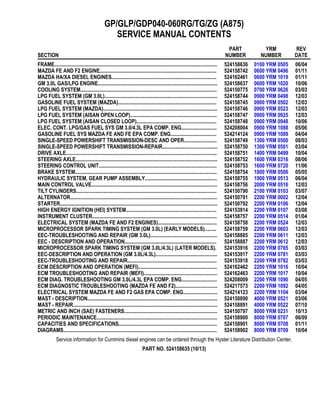
  • 1. GP/GLP/GDP040-060RG/TG/ZG (A875) SERVICE MANUAL CONTENTS SECTION PART NUMBER YRM NUMBER REV DATE FRAME............................................................................................................................ 524158636 0100 YRM 0505 06/04 MAZDA FE AND F2 ENGINE......................................................................................... 524158742 0600 YRM 0496 01/11 MAZDA HA/XA DIESEL ENGINES................................................................................ 524162461 0600 YRM 1019 01/11 GM 3.0L GAS/LPG ENGINE........................................................................................... 524158637 0600 YRM 1020 10/06 COOLING SYSTEM........................................................................................................ 524150775 0700 YRM 0626 03/03 LPG FUEL SYSTEM (GM 3.0L)...................................................................................... 524158744 0900 YRM 0498 12/03 GASOLINE FUEL SYSTEM (MAZDA)........................................................................... 524158745 0900 YRM 0502 12/03 LPG FUEL SYSTEM (MAZDA)....................................................................................... 524158746 0900 YRM 0523 12/03 LPG FUEL SYSTEM (AISAN OPEN LOOP).................................................................. 524158747 0900 YRM 0925 12/03 LPG FUEL SYSTEM (AISAN CLOSED LOOP)............................................................. 524158748 0900 YRM 0948 10/06 ELEC. CONT. LPG/GAS FUEL SYS GM 3.0/4.3L EPA COMP. ENG........................... 524208004 0900 YRM 1088 05/06 GASOLINE FUEL SYS MAZDA FE AND FE EPA COMP. ENG................................... 524214124 0900 YRM 1089 04/04 SINGLE-SPEED POWERSHIFT TRANSMISSION-DESC AND OPER......................... 524158749 1300 YRM 0500 08/03 SINGLE-SPEED POWERSHIFT TRANSMISSION-REPAIR.......................................... 524158750 1300 YRM 0501 03/04 DRIVE AXLE................................................................................................................... 524158751 1400 YRM 0499 10/04 STEERING AXLE............................................................................................................ 524158752 1600 YRM 0316 08/06 STEERING CONTROL UNIT.......................................................................................... 524158753 1600 YRM 0720 11/06 BRAKE SYSTEM............................................................................................................ 524158754 1800 YRM 0506 05/05 HYDRAULIC SYSTEM, GEAR PUMP ASSEMBLY....................................................... 524158755 1900 YRM 0513 06/04 MAIN CONTROL VALVE................................................................................................ 524158756 2000 YRM 0516 12/03 TILT CYLINDERS........................................................................................................... 524150790 2100 YRM 0103 03/07 ALTERNATOR................................................................................................................ 524150791 2200 YRM 0002 12/04 STARTER........................................................................................................................ 524150792 2200 YRM 0106 12/04 HIGH ENERGY IGNITION (HEI) SYSTEM..................................................................... 524153914 2200 YRM 0107 03/08 INSTRUMENT CLUSTER............................................................................................... 524158757 2200 YRM 0514 01/04 ELECTRICAL SYSTEM (MAZDA FE AND F2 ENGINES)............................................. 524158758 2200 YRM 0524 12/03 MICROPROCESSOR SPARK TIMING SYSTEM (GM 3.0L) (EARLY MODELS)......... 524158759 2200 YRM 0603 12/03 EEC-TROUBLESHOOTING AND REPAIR (GM 3.0L)................................................... 524158885 2200 YRM 0611 12/03 EEC - DESCRIPTION AND OPERATION...................................................................... 524158887 2200 YRM 0612 12/03 MICROPROCESSOR SPARK TIMING SYSTEM (GM 3.0L/4.3L) (LATER MODELS). 524153916 2200 YRM 0765 03/03 EEC-DESCRIPTION AND OPERATION (GM 3.0L/4.3L)............................................... 524153917 2200 YRM 0781 03/03 EEC-TROUBLESHOOTING AND REPAIR.................................................................... 524153918 2200 YRM 0782 03/03 ECM DESCRIPTION AND OPERATION (MEFI)............................................................ 524162462 2200 YRM 1016 10/04 ECM TROUBLESHOOTING AND REPAIR (MEFI)........................................................ 524162463 2200 YRM 1017 10/04 ECM DIAG. TROUBLESHOOTING GM 3.0L/4.3L EPA COMP. ENG........................... 524208009 2200 YRM 1090 04/05 ECM DIAGNOSTIC TROUBLESHOOTING (MAZDA FE AND F2)................................ 524217573 2200 YRM 1092 04/05 ELECTRICAL SYSTEM MAZDA FE AND F2 GAS EPA COMP. ENG.......................... 524214123 2200 YRM 1104 03/04 MAST - DESCRIPTION................................................................................................... 524158890 4000 YRM 0521 03/06 MAST - REPAIR.............................................................................................................. 524158891 4000 YRM 0522 07/10 METRIC AND INCH (SAE) FASTENERS....................................................................... 524150797 8000 YRM 0231 10/13 PERIODIC MAINTENANCE............................................................................................ 524158900 8000 YRM 0707 06/09 CAPACITIES AND SPECIFICATIONS........................................................................... 524158901 8000 YRM 0708 01/11 DIAGRAMS..................................................................................................................... 524158902 8000 YRM 0709 10/04 Service information for Cummins diesel engines can be ordered through the Hyster Literature Distribution Center. PART NO. 524158635 (10/13)
  • 2. 100 YRM 505 Operator Module Repair General WARNING The lift truck must be put on blocks for some types of maintenance and repair. The removal of the following assemblies will cause large changes in the center of gravity: mast, drive axle, engine and transmission, and counterweight. When the lift truck is put on blocks, put additional blocks in the following positions to maintain stability: • Before removing the mast and drive axle, put blocks under the counterweight so the lift truck cannot fall backward. • Before removing the counterweight, put blocks under the mast assembly so the lift truck cannot fall forward. The surface must be solid, even, and level when the lift truck is put on blocks. Make sure that any blocks used to support the lift truck are solid, one-piece units. See the Operating Manual or the Periodic Maintenance manual for your lift truck. This section has the description of the frame and some connected parts. See Figure 1. Procedures for the re- moval and installation of the counterweight, hood, over- head guard, and engine (including the transmission) are found in this section. Checks for the operator restraint system and procedures for the repair of fuel and hy- draulic tanks and installation of safety labels are also included. Description The frame is one weldment and includes the hydraulic tank and the fuel tank for gasoline or diesel fuel. There is a counterweight for each capacity of lift truck. The counterweights are similar, but are different weights. The muffler is fastened to the frame inside of the coun- terweight. An operator module is installed on the frame with rubber mounts. See Figure 1. The overhead guard, steering controls, instrument panel, hood, and seat are installed on the operator module. The hood is connected to the operator module with hinges. The floor plates and side access doors can be removed for access to the engine, transmission, and other components. Operator Module Repair REMOVE 1. Remove the hood and side covers. See Figure 2. 2. Remove the steering housing and instrument clus- ter from the cowl. Remove the capscrews that hold the parking brake lever to the cowl. 3. Remove the nuts and bolts at the mounts for the operator module. 4. Connect a lifting device to the overhead guard. The overhead guard and module weigh approximately 385 kg (850 lb). Lift the operator module from the frame. INSTALL NOTE: If the overhead guard was removed from the operator module, tighten the rear leg mount capscrews to 53 N•m (39 lbf ft). On GP2.00-3.00TF/RF (GP040- 060RG/TG/ZG) units, tighten the capscrews that fasten the module cowl side plate to the front legs to 66 N•m (49 lbf ft). See Figure 1. 1. Connect a lifting device to the overhead guard. The overhead guard and module weigh approximately 385 kg (850 lb). Lift the operator module onto the frame. 2. Make sure the rubber mounts are installed in the frame. Install the large washer and nut on the bot- tom of the mount. Tighten the nuts to 53 N•m (39 lbf ft). 3. Install the hood and side covers. 4. Install the steering controls and the parking brake lever. 5. Install the floor plates. 1
  • 3. Operator Module Repair 100 YRM 505 Figure 1. Frame and Operator Module 2
  • 4. 100 YRM 505 Hood and Side Covers Repair Legend for Figure 1 1. OPERATOR MODULE 2. FRAME 3. HYDRAULIC TANK 4. STEERING AXLE MOUNT 5. DRIVE AXLE MOUNT 6. CAPSCREW 7. WASHER 8. RUBBER MOUNT 9. NUT 10. COVER 11. STORAGE COMPARTMENT 12. OVERHEAD GUARD (RAISED) 13. SCREW 14. HANDLE 15. PLUG 16. LOCKWASHER 17. BAR 18. FENDER 19. CROSSMEMBER Hood and Side Covers Repair WARNING The hood and hood latch must be correctly adjusted for the correct operation of the operator restraint system. The operator’s seat is fastened to the upper hood panel. This upper hood panel opens forward for access to the engine compartment. Two hinges fasten the upper hood panel to the front plate weldment of the engine compartment. A latch mechanism with a push knob holds the upper hood panel in position during operation of the lift truck. See Figure 2. A torsion spring is fastened between the front plate weldment and the upper hood panel to help personnel when opening and closing the hood. Sound-absorbing materials are fastened inside the hood panels to reduce noise during operation. See Figure 2 and Figure 3. REMOVE Remove the floor plate and the hood and side covers. INSTALL AND ADJUST Install and adjust the hood and side covers as follows: 1. Install the crossmember onto the frame. Install the front plate weldment, but do not tighten the four capscrews. 2. Install the hinges on the upper hood panel. Do not tighten the capscrews. 3. Install the latch hook. 4. Install the upper hood panel in position on the front plate weldment. Connect the torsion spring. Install the hinge pins. Install the rod. 5. Close the upper hood panel until the rubber cush- ions are against the rear crossmember of the en- gine compartment. Align the edge of the upper hood panel with the rear crossmember of the en- gine compartment. Tighten the capscrews for the hinges. 6. When the upper hood panel is fully closed, check that the latch fully engages the latch hook. If the latch does not engage correctly, add or remove washers (shims) as necessary to adjust the latch assembly. When the adjustment is correct, tighten the capscrews that hold the latch assembly. 7. Install the hinges onto the engine compartment, but do not tighten the bolts. 8. Install the access doors on the hinges. Close the access doors. Adjust the stop bolts and front plate so that the front plate is even from side to side and the access doors will engage the tabs. Tighten the capscrews on the front plate. Tighten the jam nuts on the stop bolts. 9. Adjust the hinges so that the front edges of the ac- cess doors are even with the front plate. Tighten the bolts for the hinges. Install washers (shims) as necessary so that the access doors are against the hood seal when they are closed. 3
  • 5. Hood and Side Covers Repair 100 YRM 505 1. ACCESS DOOR (LH) 2. ACCESS DOOR (RH) 3. CROSSMEMBER 4. UPPER HOOD PANEL 5. PLATE 6. HINGE 7. ROD 8. TORSION SPRING 9. LATCH HOOK 10. SPACER 11. BUSHING 12. RUBBER CUSHION 13. TRIM 14. CAPSCREW 15. NUT 16. WASHER 17. PIN 18. COTTER PIN 19. SEAL 20. LATCH ASSEMBLY Figure 2. Hood and Side Covers Arrangement 4
  • 6. 100 YRM 505 Overhead Guard Repair 1. LATCH ASSEMBLY 2. PUSH KNOB 3. LATCH HOOK 4. LATCH (ENGAGED) 5. LATCH (DISENGAGED) 6. SHIMS (AS NECESSARY) 7. UPPER HOOD PANEL 8. FRONT PLATE 9. REAR CROSSMEMBER OF ENGINE COMPARTMENT 10. TORSION SPRING 11. STOP BOLT 12. FRONT CROSSMEMBER OF ENGINE COMPARTMENT Figure 3. Hood Assembly Overhead Guard Repair REMOVE AND INSTALL WARNING Do not operate the lift truck without the overhead guard correctly fastened to the lift truck. Changes that are made by welding, or by drilling holes that are too big or in the wrong location, can reduce the strength of the overhead guard. See the section Changes to the Overhead Guard in the Peri- odic Maintenance 8000 YRM 707 for instructions on making changes to the overhead guard. 1. Connect a crane or lifting device to remove or install the overhead guard. Disconnect the air intake at the overhead guard leg. 5
  • 7. Overhead Guard Repair 100 YRM 505 2. Disconnect any wires between the frame and the overhead guard. When the overhead guard is lifted from the frame, make sure that any electrical wires are moved through the holes in the frame so that they are not damaged. 3. There are two capscrews at each corner of the left- hand leg of the overhead guard. Remove and install the capscrews for the overhead guard as follows: a. Access to the bolts at the front of the overhead guard is under the dash panel. Remove the plastic box from the right-hand side of the dash panel. b. Access to the bolts at the rear of the overhead guard is under the rear fender wells. c. Tighten the rear leg mount capscrews to 53 N•m (39 lbf ft). On GP2.00-3.00TF/RF (GP040-060RG/TG/ZG) units, tighten the cap- screws that fasten the module cowl side plate to the front legs to 66 N•m (49 lbf ft). NOTE: The air inlet for the air filter is installed in the left-hand leg of the overhead guard. Make sure the grill is installed with the louvers pointed downward. LED BACKUP AND BRAKE LIGHTS, REPLACE NOTE: Newer models of lift trucks are equipped with LED (Light Emitting Diode) backup and brake tail lights. These light assemblies are non-repairable and must be replaced as a complete unit. See the Parts Manual for replacement LED lights. Remove 1. Disconnect negative terminal of battery and remove the key. 2. Disconnect the LED light from the chassis light har- ness. 3. Remove LED light assembly and harness from mounting bracket. See Figure 4. 4. If the LED mounting bracket must be removed from the overhead guard leg, remove the plug, screw and bracket from the overhead guard leg. Install 1. If the mounting bracket was removed, install it onto the overhead guard leg. Insert the plug and screw to attach mounting bracket to overhead guard leg. See Figure 4. 2. Install the LED light assembly and harness on the mounting bracket. 3. Connect the LED light to the chassis light harness. 4. Connect the negative terminal of battery and close the hood. A. LED ASSEMBLY WITH STANDARD EXHAUST B. LED ASSEMBLY WITH OVERHEAD EXHAUST 1. LED LIGHT 2. SCREW 3. WASHER 4. LOCKNUT 5. MOUNTING BRACKET 6. GROMMET 7. PLUG 8. SCREW 9. OVERHEAD GUARD LEG Figure 4. LED Backup and Brake Lights Assembly 6
  • 8. 100 YRM 505 Counterweight Repair Counterweight Repair WARNING The lift truck must be put on blocks for some types of maintenance and repair. The removal of the following assemblies will cause large changes in the center of gravity: mast, drive axle, engine and transmission, and counterweight. When the lift truck is put on blocks, put additional blocks in the following positions to maintain stability: • Before removing the mast and drive axle, put blocks under the counterweight so the lift truck cannot fall backward. • Before removing the counterweight, put blocks under the mast assembly so the lift truck cannot fall forward. The surface must be solid, even, and level when the lift truck is put on blocks. Make sure that any blocks used to support the lift truck are solid, one- piece units. See the Operating Manual or Periodic Maintenance 8000 YRM 707 for your lift truck. The counterweight is held in position on the frame by two hooks that are part of the frame. One M24 × 3 capscrew holds the counterweight to the lower part of the frame. REMOVE WARNING Do not operate the lift truck if the capscrew for the counterweight is not installed. When the capscrew is removed, the counterweight can fall from the lift truck. WARNING LPG can cause an explosion. Do not cause sparks or permit flammable material near the LPG system. LPG fuel systems can be disconnected indoors only if the lift truck is at least 8 m (26 ft) from any open flame, motor vehicles, electrical equipment, or ignition source. Close the shutoff valve on the LPG tank before any part of the engine fuel system is disconnected. Run the engine until the fuel in the system is used and the engine stops. If the engine will not run, close the shutoff valve on the LPG tank. Loosen the fitting on the supply hose from the LPG tank where it enters the filter unit. Permit the pressure in the fuel system to decrease slowly. Fuel leaving the fitting removes heat. Use a cloth to protect your hands from the cold fitting. 1. If the lift truck has an LPG fuel system, use the following procedure to remove the LPG tank and bracket so that the counterweight can be removed. See Figure 5. Additional information on the LPG fuel system can be found in the following sections:LPG Fuel Sys- tem, GM 2.2L and 3.0L Engines 900 YRM 498, LPG Fuel System, Mazda FE Engine 900 YRM 523, or Electronic Controlled LPG/Gasoline Fuel System, GM 3.0L and 4.3L EPA Compliant En- gines 900 YRM 1088. a. LPG tanks can be removed and replaced in- doors only if the lift truck is at least 8 m (26 ft) from any flame or ignition source. b. Move the lift truck to the area where tanks are changed. c. Turn the shutoff valve clockwise until the valve is completely closed. d. Run the engine until it stops, then turn the key switch to the OFF position. e. Disconnect the quick-disconnect fitting. f. Release the LPG tank latch and remove the tank from the bracket. 2. If an overhead exhaust is installed, remove it as shown in Figure 12. WARNING The counterweight is heavy. Make sure that the eye- bolt and lifting devices have enough capacity to lift the weight. The approximate weights of the coun- terweight castings are shown in Table 1. 3. Install a lifting eye in the lifting hole of the counter- weight. See Figure 5. Connect a crane to the lift- ing eye and raise the crane until it holds part of the weight of the counterweight. Remove the capscrew that holds the counterweight to the frame. Use the crane to lift the counterweight from the lift truck. Put the counterweight on the floor so that it has stability and will not fall over. Remove the spacers from the mounts. 7
  • 9. Counterweight Repair 100 YRM 505 1. COUNTERWEIGHT 2. CAPSCREW (M24 × 3 × 180) 3. LOCKWASHER 4. WASHER 5. TOW PIN 6. ROLL PIN 7. SEAL 8. SHIM 9. NUT 10. CAP 11. LIFTING HOLE Figure 5. Counterweight Table 1. Weight of Counterweights Model kg lbs GP 040 1,080 ±16 2380 ±35 GP 050 1406 ±21 3100 ±46 GP 060 1800 ±27 3970 ±60 GC 040 1070 ±15 2360 ±33 GC 050 1433 ±21 3160 ±46 GC 060 1855 ±28 4090 ±62 INSTALL 1. Install the spacers on the mounts. See Figure 6. Use a crane to install the counterweight on the lift truck. When the counterweight is installed, make sure the hooks on the frame fully engage the coun- terweight so it is aligned with the parts of the frame. Use the spacers to obtain a gap of 8.5 to 11.5 mm (0.33 to 0.45 in.) between the counterweight and the overhead guard leg. Install and tighten the M24 × 3 capscrew to 555 N•m (409 lbf ft). 2. If the lift truck has an LPG fuel system, use the following procedure to install the bracket and LPG tank after the counterweight has been installed: a. Before the LPG tank is installed on the lift truck, make sure the tank has fuel in it. Check the operation of the fuel gauge. Look at the fuel gauge and move the tank. If the gauge needle does not move, a new tank must be installed. b. Put the tank in the tank bracket. Make sure the tank is aligned with the alignment pin. c. Close the latch. d. Connect the quick-disconnect fitting to the shut- off valve on the tank. Use your hand to tighten the fitting. Do not open the shutoff valve until the quick-disconnect fitting is completely tight- ened. Turn the shutoff valve counterclockwise to open the valve. e. Inspect the fuel system for leaks when the shut- off valve is open. Frost on the surface of the tank, valves, or fittings or a strong odor indi- cates leakage. 3. If the lift truck has an overhead exhaust, install it as shown in Figure 12. 8
  • 10. 100 YRM 505 Exhaust System Repair Figure 6. Counterweight Installation Legend for Figure 6 1. SPACER 2. RUBBER SEAL 3. CAPSCREW Exhaust System Repair The muffler is installed inside the cavity of the counter- weight. A short exhaust pipe sends the exhaust gases from the lift truck through the grille in the counterweight. See Figure 7, Figure 8, Figure 9 or Figure 10. An optional catalytic converter can be installed in the exhaust system between the engine and the muffler. See Figure 11. The type of catalytic converter installed depends on the fuel the engine uses. See the Parts Manual for your lift truck model. The GP2.00-3.00RF/TF (GP040-060RG/TG/ZG) series of lift trucks can have an overhead exhaust system. The exhaust pipe is fastened to the top of the counterweight. See Figure 12. 9
  • 11. Exhaust System Repair 100 YRM 505 MUFFLER, REPLACE The counterweight must be removed to repair or install a new muffler or other parts of the exhaust system. See Figure 7. When connecting the exhaust pipe to the en- gine, do the following: 1. Install the adapter on the exhaust manifold. Tighten the nuts for the adapter to 40 N•m (30 lbf ft). Install the exhaust seal, spacer, and exhaust pipe. In- stall the springs and special capscrews. Tighten the special capscrews to 38 N•m (28 lbf ft). 2. On units with an overhead exhaust, tighten the cap- screws that hold the overhead exhaust to the coun- terweight to 38 N•m (28 lbf ft). Install the cover. 1. MUFFLER 2. CLAMP 3. CAPSCREW 4. NUT 5. WASHER 6. SPACER 7. PIPE 8. TUBE 9. SEAL 10. SPRING 11. LOCKWASHER 12. GASKET 13. ADAPTER Figure 7. Exhaust System (Gasoline and LPG) 10
  • 12. 100 YRM 505 Exhaust System Repair 1. MUFFLER 2. COUNTERWEIGHT EXHAUST PIPE 3. GASKET 4. EXHAUST PIPE 5. SEAL 6. SPRING 7. SPECIAL SCREW 8. OXYGEN SENSOR PORT 9. RAW GAS CHECK PORT Figure 8. Exhaust System, GM3.0L EPA Compliant 11
  • 13. Exhaust System Repair 100 YRM 505 1. MUFFLER 2. SPACER 3. BRACKET 4. CATALYTIC CONVERTER 5. DIFFUSER 6. CLAMP 7. GASKET 8. ADAPTER 9. SEAL 10. SPRING 11. SPECIAL CAPSCREW 12. PLUG Figure 9. Exhaust System (Low Emissions) 12
  • 14. 100 YRM 505 Exhaust System Repair Figure 10. EPA Compliant Exhaust System Mazda 2.0L and 2.2L 13
  • 15. Exhaust System Repair 100 YRM 505 Legend for Figure 10 1. MUFFLER 2. SPACER 3. BRACKET 4. CATALYTIC CONVERTER 5. DIFFUSER 6. CLAMP 7. GASKET 8. ADAPTER 9. SEAL 10. SPACER 11. SPRING 12. SPECIAL CAPSCREW 13. PLUG (RAW GAS CHECK PORT) 14. OXYGEN SENSOR 15. OVERHEAD EXHAUST PIPE Figure 11. Exhaust System (Diesel) 14
  • 16. 100 YRM 505 Exhaust System Repair Legend for Figure 11 1. MUFFLER 2. CLAMP 3. CAPSCREW 4. NUT 5. WASHER 6. SPACER 7. PIPE 8. TUBE 9. GASKET 10. SPRING 11. LOCKWASHER 12. ADAPTER 13. SEAL 14. CATALYTIC CONVERTER 15. HEAT SHIELD 16. FITTING Figure 12. Overhead Exhaust Legend for Figure 12 1. TUBE 2. TAILPIPE 3. CAPSCREW 4. LOCKWASHER 5. WASHER 6. COVER 7. CLAMP 15
  • 17. Radiator and Cooling System Repair 100 YRM 505 Radiator and Cooling System Repair REMOVE WARNING DO NOT remove the radiator cap while it is hot. Hot coolant and steam can cause burns. Make sure the label is on the radiator cap. See Figure 17. 1. Use the drain valve and drain the coolant from the radiator. Remove the bottom radiator hose and drain the coolant from the engine. See Figure 13 and Figure 14. 2. Remove the capscrews that fasten the fan to the hub. Remove the capscrews that hold the fan shroud to the radiator. Remove both the fan and the fan shroud. 3. Disconnect the top coolant hose at the radiator. Disconnect the lines to the oil cooler in the side of the radiator. Put caps on the open lines and ports. Remove the capscrews that hold the radiator to the frame. Remove the radiator. INSTALL 1. Install the radiator. See Figure 13 and Figure 14. Install the fan and fan shroud in position on the radi- ator. Install the capscrews that hold the fan shroud. Install the capscrews that fasten the fan to the hub. Tighten the capscrews to 26 N•m (19 lbf ft). 2. Connect the upper coolant hoses at the radiator. Connect the lines for transmission oil to the oil cooler in the radiator. 1. RADIATOR 2. RADIATOR CAP 3. AUXILIARY COOLANT RESERVOIR 4. SHROUD 5. DRAIN VALVE Figure 13. Cooling System (Older) 16
  • 18. 100 YRM 505 Radiator and Cooling System Repair A. MAZDA FE AND F2 ENGINES 1. RADIATOR 2. RADIATOR CAP 3. AUXILIARY COOLANT RESERVOIR 4. SHROUD 5. DRAIN VALVE Figure 14. Cooling System (Newer) 17
  • 19. Operator Restraint System Repair 100 YRM 505 Operator Restraint System Repair The seat belt, hip restraint, seat and mount, hood, and latch are all part of the operator restraint system. Each item must be checked to make sure it is fastened cor- rectly, functions correctly, and is in good condition. See Figure 15. The end of the seat belt must fasten correctly in the latch. Make sure the seat belt pulls from the retractor assembly and retracts smoothly. The seat belt must be in good condition. A seat belt that is damaged or worn will not give protection when it is needed. Adjust the hood, hood latch, and latch striker when any of the parts of the operator restraint system are installed or replaced. See Hood and Side Covers Repair for the adjustment procedures. 1. HOOD LATCH 2. LATCH HOOK 3. PUSH KNOB 4. SEAT 5. HIP RESTRAINT 6. SEAT BELT 7. UPPER HOOD PANEL 8. HINGE 9. TORSION SPRING Figure 15. Hood and Seat Check 18
  • 20. 100 YRM 505 Engine Repair Engine Repair REMOVE ENGINE ONLY WARNING The lift truck must be put on blocks for some types of maintenance and repair. The removal of the following assemblies will cause large changes in the center of gravity: mast, drive axle, engine and transmission, and counterweight. When the lift truck is put on blocks, put additional blocks in the following positions to maintain stability: • Before removing the mast and drive axle, put blocks under the counterweight so the lift truck cannot fall backward. • Before removing the counterweight, put blocks under the mast assembly so the lift truck cannot fall forward. The surface must be solid, even, and level when the lift truck is put on blocks. Make sure that any blocks used to support the lift truck are solid, one-piece units. See the Operating Manual or the Periodic Maintenance section for your lift truck. The engine can be removed with or without the trans- mission. Follow this procedure to remove the engine without the transmission. WARNING Always disconnect the cables at the battery before you make repairs to the engine. Disconnect the ca- ble at the negative terminal first. 1. Remove the floor plates. Remove the hood and side covers. Remove the crossmember that is the hood mount. Remove the air filter and battery. Re- move the radiator. 2. Disconnect the throttle linkage. Disconnect the ex- haust system. 3. Disconnect the wires and wiring harnesses at the engine. Disconnect the fuel lines at the engine. 4. Connect a lifting device to the engine. Put a block under the transmission housing as a support. 5. Remove the capscrews that hold the torque con- verter housing to the flywheel housing. Remove the capscrews that hold the drive plate to the torque converter. WARNING The engine is heavy. Make sure that any lifting de- vice has enough capacity to lift the engine. The en- gine can weigh approximately 340 kg (750 lb). 6. Remove the nuts and bolts from the engine mounts. Use the lifting device to carefully move the engine away from the torque converter. Make sure all hoses, wires, and cables are disconnected from the engine, then lift the engine from the frame. REMOVE ENGINE AND TRANSMISSION The engine can be removed with or without the trans- mission. Follow this procedure to remove the engine with the transmission. 1. Remove the mast. See the section Mast, Repairs 4000 YRM 522. Put the lift truck on blocks so you have access under the lift truck. See the section Periodic Maintenance 8000 YRM 707. 2. Perform Step 1 through Step 3 from Remove En- gine Only. 3. Remove the crossmember for the brake and throttle pedals. 4. Remove the hydraulic hose between the pump and the tank. Put a cap on the tank fitting. Remove the hydraulic filter and hoses. Remove the supply line to the main control valve. 5. Drain the oil from the axle housing. Remove the capscrews that hold the axle shafts to the hubs. Re- move the axle shafts. Disconnect the brake lines and parking brake cables. Remove the capscrews that hold the transmission housing to the axle hous- ing. WARNING The engine and transmission are heavy. Make sure that any lifting device has enough capacity to lift the weight. The engine and transmission can weigh approximately 680 kg (1500 lb). 6. Connect a lifting device to the engine and transmis- sion. Make sure the engine and transmission as- sembly can be raised at an angle so they will clear the frame. Remove the nuts and bolts from the en- gine mounts. Use the lifting device to carefully lift the engine and transmission from the frame. 19
  • 21. Engine Repair 100 YRM 505 INSTALL ENGINE ONLY The engine can be installed with or without the transmis- sion. Follow this procedure to install the engine without the transmission. WARNING The engine is heavy. Make sure that any lifting de- vice has enough capacity to lift the engine. The en- gine can weigh approximately 340 kg (750 lb). 1. Make sure the torque converter is installed in the transmission and the drive plate is on the flywheel. Connect a lifting device to the engine. Lift the engine into the frame. Carefully align the drive plate with the transmission. See the section Single-Speed Powershift Transmission, Trou- bleshooting and Repair 1300 YRM 501. Make sure the pilot on the torque converter is in the hole in the flywheel. Install the capscrews that hold the torque converter housing to the flywheel housing. Install the capscrews that hold the drive plate to the torque converter. 2. Install the nuts and bolts for the engine mounts. In- stall the parts of the mounts as shown in Figure 16. Use a maximum of three spacers to bring the en- gine mounts within 1.0 mm (0.04 in.) of a vertical position. Tighten the nuts to 66 N•m (49 lbf ft). 3. Install the radiator and connect the coolant hoses and the lines to the transmission. 4. Install the crossmember that is the hood mount. Connect the wires and wiring harnesses at the en- gine. Connect the fuel lines at the engine. 5. Connect the throttle linkage. Connect the exhaust system. Install the air filter assembly. 6. Install the battery. Install the side covers and the hood. 7. Check all fluid levels as described in Periodic Maintenance 8000 YRM 707. 1. BOLT 2. ENGINE MOUNT 3. FLAT WASHER 4. SPACER 5. CUP 6. RUBBER MOUNT 7. TUBE SPACER 8. BUMPER 9. LOCKWASHER 10. NUT Figure 16. Engine Mounts 20
  • 22. 100 YRM 505 Fuel and Hydraulic Tanks Repair INSTALL ENGINE AND TRANSMISSION The engine can be installed with or without the trans- mission. Follow this procedure to install the engine with the transmission. 1. Put the lift truck on blocks so you have access un- der the lift truck. See the section Periodic Mainte- nance 8000 YRM 707. WARNING The engine and transmission are heavy. Make sure that any lifting device has enough capacity to lift the weight. The engine and transmission can weigh approximately 680 kg (1500 lb). 2. Apply a gasket sealant to the flange of the axle housing. Connect a lifting device to the engine and transmission. Lift the engine and transmission into the frame. Connect the transmission housing to the axle housing. Install a capscrew in the "tight fit" hole first. This hole is on the side of the transmission with the dipstick, near the top. Install the remain- ing capscrews. Tighten the capscrews to 38 N•m (28 lbf ft). 3. Install the nuts and bolts for the engine mounts. In- stall the parts of the mounts as shown in Figure 16. Use a maximum of three spacers (4) to bring the engine mounts within 1.0 mm (0.04 in.) of a verti- cal position. Tighten the nuts to 66 N•m (49 lbf ft). 4. Install the hydraulic hose between the pump and the tank. Install the hydraulic filter and hoses. Con- nect the supply line to the main control valve. 5. Install the crossmember for the brake and throttle pedals. 6. Perform Step 3 through Step 7 from Install Engine Only. Fuel and Hydraulic Tanks Repair INSPECT WARNING Special procedures must be followed when large leaks or other repairs need welding or cutting. All work must be done by authorized personnel. If the tank is cleaned inside a building, make sure there is enough ventilation. See the following manuals for additional information: • Safe Practices for Welding and Cutting Contain- ers That Have Held Combustibles by the Ameri- can Welding Society, F4.1 - 1999. • Safety in Welding and Cutting, American National Standard, AWS Z 49.1 - 1999. WARNING Do not use tools that can make sparks, heat, or static electricity. The vapors in the tank can cause an explosion. Make a visual inspection of all sides of the tank. Inspect the welds for cracks and leakage. Check for wet areas, accumulation of dirt, and loose or missing paint caused by leakage. Areas of the tank that are not easily seen can be checked with an inspection mirror and a light that is approved for locations with flammable vapors. SMALL LEAKS, REPAIR Use the following procedure to repair small leaks: 1. Use steam to clean the area around the leak. Re- move all paint and dirt around the leak. 2. Apply Loctite® 290 to the leak. Follow the instruc- tions of the manufacturer. LARGE LEAKS, REPAIR 1. Use one of the procedures described under Clean to clean and prepare the tank for repairs. 2. Contact your dealer for Yale lift trucks for welding instructions. 3. Use acceptable welding practices to repair the tank. See the American National Standard Safety in Welding and Cutting, AWS Z 49.1 - 1999. 21
  • 23. Fuel and Hydraulic Tanks Repair 100 YRM 505 CLEAN WARNING When cleaning the tank, do not use solutions that make dangerous gases at normal temperatures or when heated. Wear eye and face protection. Protect the body from burns. When cleaning with steam, use a hose with a minimum diameter of 19 mm (0.75 in.). Control the pressure of the steam by a valve installed at the nozzle of the hose. If a metal nozzle is used, it must be made of a material that does not make sparks. Make an electrical connec- tion between the nozzle and the tank. Connect a ground wire to the tank to prevent static electricity. Steam Method of Cleaning Use the following procedure to clean the tank with steam: 1. Remove all the parts from the tank. Install the drain plug. 2. Fill the tank 1/4 full with a solution of water and sodium bicarbonate or sodium carbonate. Mix 0.5 kg (1 lb) per 4 liter (1 gal) of water. 3. Mix the solution in the tank using air pressure. Make sure all the surfaces on the inside of the tank are flushed with the solution. Drain the tank. 4. Put steam into the tank until the tank does not have odors and the metal is hot. Steam vapors must come from all the openings. 5. Flush the inside of the tank with boiling water. Make sure all the loose material is removed from the in- side of the tank. 6. Make an inspection of the inside of the tank. If it is not clean, repeat Step 4 and Step 5 and make another inspection. When making inspections, use a light that is approved for locations with flammable vapors. 7. Put plugs in all the openings in the tank. Wait 15 minutes, then remove the inlet and outlet plugs. Test a sample of the vapor with a special indicator for gas vapors. If the amount of flammable vapors is above the lower flammable limit, repeat the clean- ing procedures. Chemical Solution Method of Cleaning WARNING When cleaning the tank, do not use solutions that make dangerous gases at normal temperatures or when heated. Wear eye and face protection. Protect the body from burns. If the tank cannot be cleaned with steam, use the fol- lowing procedure: 1. Mix a solution of water and trisodium phosphate or a cleaning compound with an alkaline base. Follow the instructions given by the manufacturer. 2. Fill the tank with the cleaning solution. Use com- pressed air to mix the solution in the tank. 3. Drain the tank. Flush the inside of the tank with hot (boiling) water. Make sure all the cleaning com- pound is removed. 4. Make an inspection of the inside of the tank. If the tank is not clean, repeat Step 1 through Step 3. Make another inspection of the tank. When mak- ing inspections, use a light that is approved for lo- cations with flammable vapors. 5. Check the tank for flammable vapors using special indicator for gas vapors. If the amount of flammable vapors is not below the lower flammable limit, re- peat the cleaning procedures. ADDITIONAL PREPARATIONS FOR REPAIR If nitrogen gas or carbon dioxide gas is available, pre- pare the tank for welding using these gases. See the manual Safe Practices for Welding and Cutting Con- tainers That Have Held Combustibles by the American Welding Society, F4.1 - 1999. If these gases are not available, another method using water can be used as follows: 1. Fill the tank with water to just below the point where the work will be done. Make sure the space above the level of the water has a vent. 2. Use acceptable welding practices to repair the tank. See the American National Standard Safety in Welding and Cutting, AWS Z 49.1 - 1999. 22
  • 24. 100 YRM 505 Safety Labels Safety Labels WARNING Safety labels are installed on the lift truck to give information about operation and possible hazards. It is important that all safety labels are installed on the lift truck and can be read. DO NOT add to or modify the lift truck. Any change to the lift truck, the tires, or its equipment can change the lifting capacity. The lift truck must be rated as equipped, and the nameplate must show the new capacity rating. Contact your dealer for a new nameplate. WARNING Cleaning solvents can be flammable and toxic and can cause skin irritation. When using cleaning sol- vents, always follow the recommendations of the manufacturer. If a new label must be installed, use the following pro- cedure to install a new label (Figure 17): 1. Make sure the surface is dry and has no oil or grease. Do not use solvent on new paint. Clean the surface of old paint with a cleaning solvent. 2. Remove the paper from the back of the label. Do not touch the adhesive surface. 3. Carefully hold the label in the correct position above the surface. The label cannot be moved after it touches the surface. Put the label on the surface. Make sure that all air is removed from under the label and the corners and edges are tight. 23
  • 25. Safety Labels 100 YRM 505 Figure 17. Safety Label Positions 24
  • 26. Thank you very much for your reading. Please Click Here Then Get More Information.