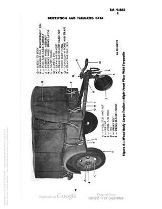
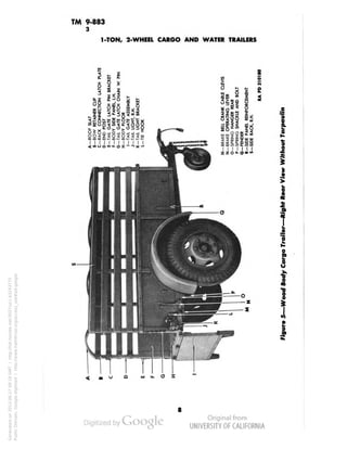
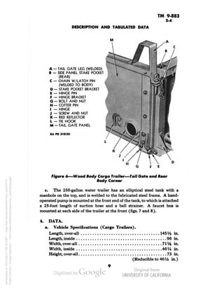
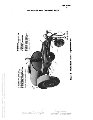
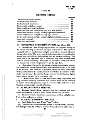
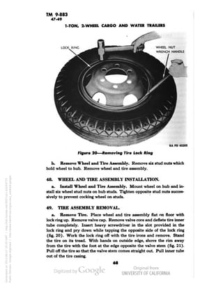
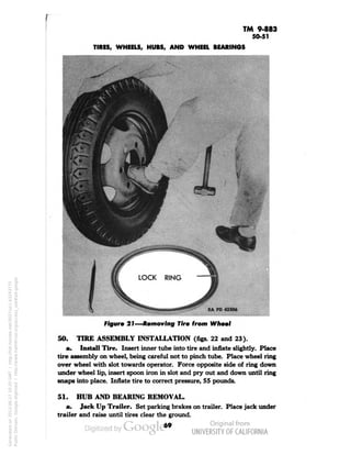
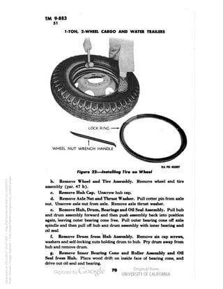
This document provides descriptions and specifications for 1-ton, 2-wheel cargo and water trailers used by the Army. It describes the different trailer models, including all-steel and wood body cargo trailers, and a 250-gallon water trailer. It provides details on trailer components like the drawbar, parking wheel, frame, springs, lights, brakes, and hitches. Tabulated data lists specifications for cargo trailer length, width, height and other dimensions. The document is intended to inform operators on trailer use and maintenance personnel on repairs.
![TM 9-883
4
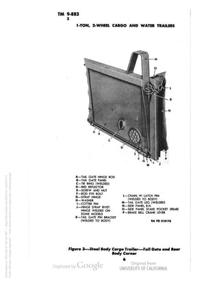
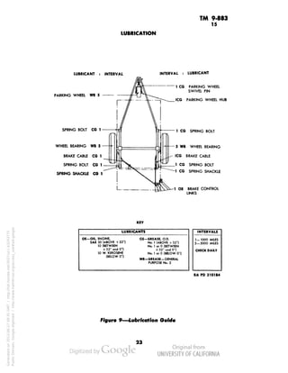
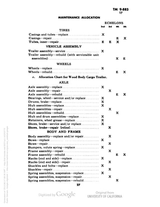
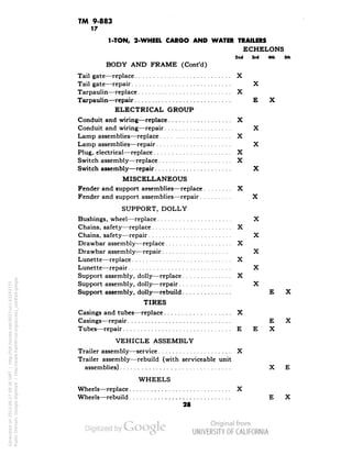
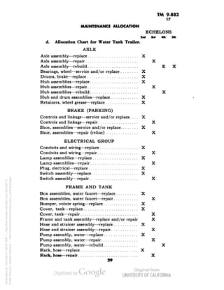
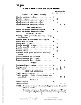
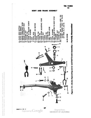
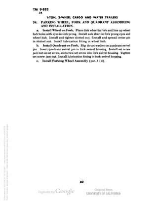
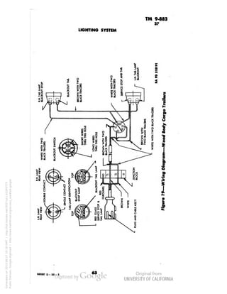
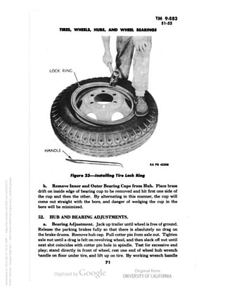
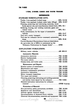
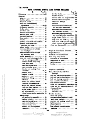
1-TON, 2-WHEEL CARGO AND WATER TRAILERS
d Osj
£
3
1
I
]
'JnUiilisU-U-
10
Generated on 2013-06-27 09:20 GMT / http://hdl.handle.net/2027/uc1.b3243775
Public Domain, Google-digitized / http://www.hathitrust.org/access_use#pd-google](https://image.slidesharecdn.com/tm9-883-141031104853-conversion-gate01/85/TM-9-883-completo-13-320.jpg)
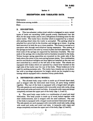
![TM 9-883
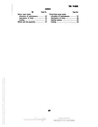
AXLE AND SPRINGS
61
£5 5 3§t ,
->., Z 1 = 3;
"" iu 7 > I
• g'=8«i
UJ U.
51 ^5
K5 ooa
»sl
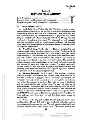
Z^ao-SC*-1"
|3&!ii
gSz^slo
illlBlilllllpiiiil.
I 1111 I I I I 111]111 I I 11
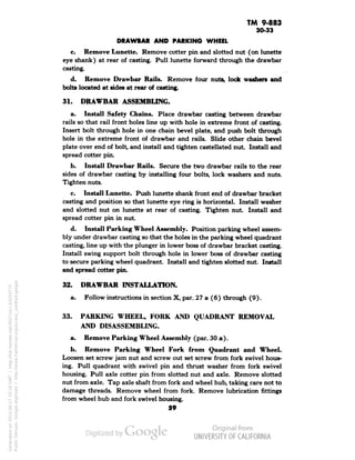
". Wot «l H
*e
«H
sSg.
I
^
]
!
i
*
1
i
•1
Generated on 2013-06-27 10:41 GMT / http://hdl.handle.net/2027/uc1.b3243775
Public Domain, Google-digitized / http://www.hathitrust.org/access_use#pd-google](https://image.slidesharecdn.com/tm9-883-141031104853-conversion-gate01/85/TM-9-883-completo-84-320.jpg)


![Manual Circuito Eléctrico Renault 9 - [Amigos Renault 9 Argentina]](https://cdn.slidesharecdn.com/ss_thumbnails/circuitoelectricorenault9-140405160638-phpapp01-thumbnail.jpg?width=640&height=640&fit=bounds)


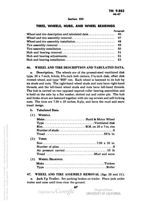
![DESIGN AND FABRICATION OF THE IBM 90-90 SEAT BELT CLAMP KIA VEHICLE[1].pptx 2...](https://cdn.slidesharecdn.com/ss_thumbnails/designandfabricationoftheibm90-90seatbeltclampkiavehicle1-260116160442-70ff67fc-thumbnail.jpg?width=640&height=640&fit=bounds)


