JCB 525-58 TELESCOPIC HANDLER Service Repair Manual ALL:561001 Onwardssjehfd ksejfm
This is the Highly Detailed factory service repair manual for theJCB 525-58 TELESCOPIC HANDLER, this Service Manual has detailed illustrations as well as step by step instructions,It is 100 percents complete and intact. they are specifically written for the do-it-yourself-er as well as the experienced mechanic.JCB 525-58 TELESCOPIC HANDLER Service Repair Workshop Manual provides step-by-step instructions based on the complete dis-assembly of the machine. It is this level of detail, along with hundreds of photos and illustrations, that guide the reader through each service and repair procedure. Complete download comes in pdf format which can work under all PC based windows operating system and Mac also, All pages are printable. Using this repair manual is an inexpensive way to keep your vehicle working properly.
Service Repair Manual Covers:
General
Hydraulics
Body and Framework
PlaceAce Control System
Servo Control System
Engine
Transmission
Axles
Brakes
Hydraulic Steering
Electrics
Service Tools
Index
File Format: PDF
Compatible: All Versions of Windows & Mac
Language: English
Requirements: Adobe PDF Reader
NO waiting, Buy from responsible seller and get INSTANT DOWNLOAD, Without wasting your hard-owned money on uncertainty or surprise! All pages are is great to haveJCB 525-58 TELESCOPIC HANDLER Service Repair Workshop Manual.
Looking for some other Service Repair Manual,please check:
https://www.aservicemanualpdf.com/
Thanks for visiting!
This is the Highly Detailed factory service repair manual for theJOHN DEERE 5310 TRACTOR, this Service Manual has detailed illustrations as well as step by step instructions,It is 100 percents complete and intact. they are specifically written for the do-it-yourself-er as well as the experienced mechanic.JOHN DEERE 5310 TRACTOR Service Repair Workshop Manual provides step-by-step instructions based on the complete dis-assembly of the machine. It is this level of detail, along with hundreds of photos and illustrations, that guide the reader through each service and repair procedure. Complete download comes in pdf format which can work under all PC based windows operating system and Mac also, All pages are printable. Using this repair manual is an inexpensive way to keep your vehicle working properly.
Service Repair Manual Covers:
Introduction
General information
Engine repair
Fuel and air repair
Electrical repair
Power train repair
Steering and brake repair
Hydraulic repair
Miscellaneous repair
Operator station repair
Test and adjustment specifications / Operational checkout procedures
Engine operation, tests and adjustments
Fuel / air operation, tests and adjustments
Electrical system operation, tests & adjustments
Power train operation, tests & adjustments
Steering and brake operation, tests & adjustments
Hydraulic system operation, tests & adjustments
Operator station
Dealer fabricated tools
Index
File Format: PDF
Compatible: All Versions of Windows & Mac
Language: English
Requirements: Adobe PDF Reader
NO waiting, Buy from responsible seller and get INSTANT DOWNLOAD, Without wasting your hard-owned money on uncertainty or surprise! All pages are is great to haveJOHN DEERE 5310 TRACTOR Service Repair Workshop Manual.
Looking for some other Service Repair Manual,please check:
https://www.aservicemanualpdf.com/
Thanks for visiting!
Core technology of Hyundai Motor Group's EV platform 'E-GMP'Hyundai Motor Group
What’s the force behind Hyundai Motor Group's EV performance and quality?
Maximized driving performance and quick charging time through high-density battery pack and fast charging technology and applicable to various vehicle types!
Discover more about Hyundai Motor Group’s EV platform ‘E-GMP’!
What Does the PARKTRONIC Inoperative, See Owner's Manual Message Mean for You...Autohaus Service and Sales
Learn what "PARKTRONIC Inoperative, See Owner's Manual" means for your Mercedes-Benz. This message indicates a malfunction in the parking assistance system, potentially due to sensor issues or electrical faults. Prompt attention is crucial to ensure safety and functionality. Follow steps outlined for diagnosis and repair in the owner's manual.
In this presentation, we have discussed a very important feature of BMW X5 cars… the Comfort Access. Things that can significantly limit its functionality. And things that you can try to restore the functionality of such a convenient feature of your vehicle.
Fleet management these days is next to impossible without connected vehicle solutions. Why? Well, fleet trackers and accompanying connected vehicle management solutions tend to offer quite a few hard-to-ignore benefits to fleet managers and businesses alike. Let’s check them out!
Comprehensive program for Agricultural Finance, the Automotive Sector, and Empowerment . We will define the full scope and provide a detailed two-week plan for identifying strategic partners in each area within Limpopo, including target areas.:
1. Agricultural : Supporting Primary and Secondary Agriculture
• Scope: Provide support solutions to enhance agricultural productivity and sustainability.
• Target Areas: Polokwane, Tzaneen, Thohoyandou, Makhado, and Giyani.
2. Automotive Sector: Partnerships with Mechanics and Panel Beater Shops
• Scope: Develop collaborations with automotive service providers to improve service quality and business operations.
• Target Areas: Polokwane, Lephalale, Mokopane, Phalaborwa, and Bela-Bela.
3. Empowerment : Focusing on Women Empowerment
• Scope: Provide business support support and training to women-owned businesses, promoting economic inclusion.
• Target Areas: Polokwane, Thohoyandou, Musina, Burgersfort, and Louis Trichardt.
We will also prioritize Industrial Economic Zone areas and their priorities.
Sign up on https://profilesmes.online/welcome/
To be eligible:
1. You must have a registered business and operate in Limpopo
2. Generate revenue
3. Sectors : Agriculture ( primary and secondary) and Automative
Women and Youth are encouraged to apply even if you don't fall in those sectors.
Things to remember while upgrading the brakes of your carjennifermiller8137
Upgrading the brakes of your car? Keep these things in mind before doing so. Additionally, start using an OBD 2 GPS tracker so that you never miss a vehicle maintenance appointment. On top of this, a car GPS tracker will also let you master good driving habits that will let you increase the operational life of your car’s brakes.
What Exactly Is The Common Rail Direct Injection System & How Does It WorkMotor Cars International
Learn about Common Rail Direct Injection (CRDi) - the revolutionary technology that has made diesel engines more efficient. Explore its workings, advantages like enhanced fuel efficiency and increased power output, along with drawbacks such as complexity and higher initial cost. Compare CRDi with traditional diesel engines and discover why it's the preferred choice for modern engines.
5 Warning Signs Your BMW's Intelligent Battery Sensor Needs AttentionBertini's German Motors
IBS monitors and manages your BMW’s battery performance. If it malfunctions, you will have to deal with an array of electrical issues in your vehicle. Recognize warning signs like dimming headlights, frequent battery replacements, and electrical malfunctions to address potential IBS issues promptly.
𝘼𝙣𝙩𝙞𝙦𝙪𝙚 𝙋𝙡𝙖𝙨𝙩𝙞𝙘 𝙏𝙧𝙖𝙙𝙚𝙧𝙨 𝙞𝙨 𝙫𝙚𝙧𝙮 𝙛𝙖𝙢𝙤𝙪𝙨 𝙛𝙤𝙧 𝙢𝙖𝙣𝙪𝙛𝙖𝙘𝙩𝙪𝙧𝙞𝙣𝙜 𝙩𝙝𝙚𝙞𝙧 𝙥𝙧𝙤𝙙𝙪𝙘𝙩𝙨. 𝙒𝙚 𝙝𝙖𝙫𝙚 𝙖𝙡𝙡 𝙩𝙝𝙚 𝙥𝙡𝙖𝙨𝙩𝙞𝙘 𝙜𝙧𝙖𝙣𝙪𝙡𝙚𝙨 𝙪𝙨𝙚𝙙 𝙞𝙣 𝙖𝙪𝙩𝙤𝙢𝙤𝙩𝙞𝙫𝙚 𝙖𝙣𝙙 𝙖𝙪𝙩𝙤 𝙥𝙖𝙧𝙩𝙨 𝙖𝙣𝙙 𝙖𝙡𝙡 𝙩𝙝𝙚 𝙛𝙖𝙢𝙤𝙪𝙨 𝙘𝙤𝙢𝙥𝙖𝙣𝙞𝙚𝙨 𝙗𝙪𝙮 𝙩𝙝𝙚 𝙜𝙧𝙖𝙣𝙪𝙡𝙚𝙨 𝙛𝙧𝙤𝙢 𝙪𝙨.
Over the 10 years, we have gained a strong foothold in the market due to our range's high quality, competitive prices, and time-lined delivery schedules.
Why Is Your BMW X3 Hood Not Responding To Release CommandsDart Auto
Experiencing difficulty opening your BMW X3's hood? This guide explores potential issues like mechanical obstruction, hood release mechanism failure, electrical problems, and emergency release malfunctions. Troubleshooting tips include basic checks, clearing obstructions, applying pressure, and using the emergency release.
"Trans Failsafe Prog" on your BMW X5 indicates potential transmission issues requiring immediate action. This safety feature activates in response to abnormalities like low fluid levels, leaks, faulty sensors, electrical or mechanical failures, and overheating.
Ever been troubled by the blinking sign and didn’t know what to do?
Here’s a handy guide to dashboard symbols so that you’ll never be confused again!
Save them for later and save the trouble!
Yale a875 gdp040 060 rg-tg-zg lift truck service repair manual
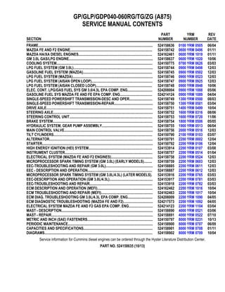
1. GP/GLP/GDP040-060RG/TG/ZG (A875)
SERVICE MANUAL CONTENTS
SECTION
PART
NUMBER
YRM
NUMBER
REV
DATE
FRAME............................................................................................................................ 524158636 0100 YRM 0505 06/04
MAZDA FE AND F2 ENGINE......................................................................................... 524158742 0600 YRM 0496 01/11
MAZDA HA/XA DIESEL ENGINES................................................................................ 524162461 0600 YRM 1019 01/11
GM 3.0L GAS/LPG ENGINE........................................................................................... 524158637 0600 YRM 1020 10/06
COOLING SYSTEM........................................................................................................ 524150775 0700 YRM 0626 03/03
LPG FUEL SYSTEM (GM 3.0L)...................................................................................... 524158744 0900 YRM 0498 12/03
GASOLINE FUEL SYSTEM (MAZDA)........................................................................... 524158745 0900 YRM 0502 12/03
LPG FUEL SYSTEM (MAZDA)....................................................................................... 524158746 0900 YRM 0523 12/03
LPG FUEL SYSTEM (AISAN OPEN LOOP).................................................................. 524158747 0900 YRM 0925 12/03
LPG FUEL SYSTEM (AISAN CLOSED LOOP)............................................................. 524158748 0900 YRM 0948 10/06
ELEC. CONT. LPG/GAS FUEL SYS GM 3.0/4.3L EPA COMP. ENG........................... 524208004 0900 YRM 1088 05/06
GASOLINE FUEL SYS MAZDA FE AND FE EPA COMP. ENG................................... 524214124 0900 YRM 1089 04/04
SINGLE-SPEED POWERSHIFT TRANSMISSION-DESC AND OPER......................... 524158749 1300 YRM 0500 08/03
SINGLE-SPEED POWERSHIFT TRANSMISSION-REPAIR.......................................... 524158750 1300 YRM 0501 03/04
DRIVE AXLE................................................................................................................... 524158751 1400 YRM 0499 10/04
STEERING AXLE............................................................................................................ 524158752 1600 YRM 0316 08/06
STEERING CONTROL UNIT.......................................................................................... 524158753 1600 YRM 0720 11/06
BRAKE SYSTEM............................................................................................................ 524158754 1800 YRM 0506 05/05
HYDRAULIC SYSTEM, GEAR PUMP ASSEMBLY....................................................... 524158755 1900 YRM 0513 06/04
MAIN CONTROL VALVE................................................................................................ 524158756 2000 YRM 0516 12/03
TILT CYLINDERS........................................................................................................... 524150790 2100 YRM 0103 03/07
ALTERNATOR................................................................................................................ 524150791 2200 YRM 0002 12/04
STARTER........................................................................................................................ 524150792 2200 YRM 0106 12/04
HIGH ENERGY IGNITION (HEI) SYSTEM..................................................................... 524153914 2200 YRM 0107 03/08
INSTRUMENT CLUSTER............................................................................................... 524158757 2200 YRM 0514 01/04
ELECTRICAL SYSTEM (MAZDA FE AND F2 ENGINES)............................................. 524158758 2200 YRM 0524 12/03
MICROPROCESSOR SPARK TIMING SYSTEM (GM 3.0L) (EARLY MODELS)......... 524158759 2200 YRM 0603 12/03
EEC-TROUBLESHOOTING AND REPAIR (GM 3.0L)................................................... 524158885 2200 YRM 0611 12/03
EEC - DESCRIPTION AND OPERATION...................................................................... 524158887 2200 YRM 0612 12/03
MICROPROCESSOR SPARK TIMING SYSTEM (GM 3.0L/4.3L) (LATER MODELS). 524153916 2200 YRM 0765 03/03
EEC-DESCRIPTION AND OPERATION (GM 3.0L/4.3L)............................................... 524153917 2200 YRM 0781 03/03
EEC-TROUBLESHOOTING AND REPAIR.................................................................... 524153918 2200 YRM 0782 03/03
ECM DESCRIPTION AND OPERATION (MEFI)............................................................ 524162462 2200 YRM 1016 10/04
ECM TROUBLESHOOTING AND REPAIR (MEFI)........................................................ 524162463 2200 YRM 1017 10/04
ECM DIAG. TROUBLESHOOTING GM 3.0L/4.3L EPA COMP. ENG........................... 524208009 2200 YRM 1090 04/05
ECM DIAGNOSTIC TROUBLESHOOTING (MAZDA FE AND F2)................................ 524217573 2200 YRM 1092 04/05
ELECTRICAL SYSTEM MAZDA FE AND F2 GAS EPA COMP. ENG.......................... 524214123 2200 YRM 1104 03/04
MAST - DESCRIPTION................................................................................................... 524158890 4000 YRM 0521 03/06
MAST - REPAIR.............................................................................................................. 524158891 4000 YRM 0522 07/10
METRIC AND INCH (SAE) FASTENERS....................................................................... 524150797 8000 YRM 0231 10/13
PERIODIC MAINTENANCE............................................................................................ 524158900 8000 YRM 0707 06/09
CAPACITIES AND SPECIFICATIONS........................................................................... 524158901 8000 YRM 0708 01/11
DIAGRAMS..................................................................................................................... 524158902 8000 YRM 0709 10/04
Service information for Cummins diesel engines can be ordered through the Hyster Literature Distribution Center.
PART NO. 524158635 (10/13)
2. 100 YRM 505 Operator Module Repair
General
WARNING
The lift truck must be put on blocks for some types
of maintenance and repair. The removal of the
following assemblies will cause large changes in
the center of gravity: mast, drive axle, engine and
transmission, and counterweight. When the lift
truck is put on blocks, put additional blocks in the
following positions to maintain stability:
• Before removing the mast and drive axle, put
blocks under the counterweight so the lift truck
cannot fall backward.
• Before removing the counterweight, put blocks
under the mast assembly so the lift truck cannot
fall forward.
The surface must be solid, even, and level when the
lift truck is put on blocks. Make sure that any blocks
used to support the lift truck are solid, one-piece
units. See the Operating Manual or the Periodic
Maintenance manual for your lift truck.
This section has the description of the frame and some
connected parts. See Figure 1. Procedures for the re-
moval and installation of the counterweight, hood, over-
head guard, and engine (including the transmission) are
found in this section. Checks for the operator restraint
system and procedures for the repair of fuel and hy-
draulic tanks and installation of safety labels are also
included.
Description
The frame is one weldment and includes the hydraulic
tank and the fuel tank for gasoline or diesel fuel. There
is a counterweight for each capacity of lift truck. The
counterweights are similar, but are different weights.
The muffler is fastened to the frame inside of the coun-
terweight.
An operator module is installed on the frame with rubber
mounts. See Figure 1. The overhead guard, steering
controls, instrument panel, hood, and seat are installed
on the operator module. The hood is connected to the
operator module with hinges. The floor plates and side
access doors can be removed for access to the engine,
transmission, and other components.
Operator Module Repair
REMOVE
1. Remove the hood and side covers. See Figure 2.
2. Remove the steering housing and instrument clus-
ter from the cowl. Remove the capscrews that hold
the parking brake lever to the cowl.
3. Remove the nuts and bolts at the mounts for the
operator module.
4. Connect a lifting device to the overhead guard. The
overhead guard and module weigh approximately
385 kg (850 lb). Lift the operator module from the
frame.
INSTALL
NOTE: If the overhead guard was removed from the
operator module, tighten the rear leg mount capscrews
to 53 N•m (39 lbf ft). On GP2.00-3.00TF/RF (GP040-
060RG/TG/ZG) units, tighten the capscrews that fasten
the module cowl side plate to the front legs to 66 N•m
(49 lbf ft). See Figure 1.
1. Connect a lifting device to the overhead guard. The
overhead guard and module weigh approximately
385 kg (850 lb). Lift the operator module onto the
frame.
2. Make sure the rubber mounts are installed in the
frame. Install the large washer and nut on the bot-
tom of the mount. Tighten the nuts to 53 N•m
(39 lbf ft).
3. Install the hood and side covers.
4. Install the steering controls and the parking brake
lever.
5. Install the floor plates.
1
4. 100 YRM 505 Hood and Side Covers Repair
Legend for Figure 1
1. OPERATOR MODULE
2. FRAME
3. HYDRAULIC TANK
4. STEERING AXLE MOUNT
5. DRIVE AXLE MOUNT
6. CAPSCREW
7. WASHER
8. RUBBER MOUNT
9. NUT
10. COVER
11. STORAGE COMPARTMENT
12. OVERHEAD GUARD (RAISED)
13. SCREW
14. HANDLE
15. PLUG
16. LOCKWASHER
17. BAR
18. FENDER
19. CROSSMEMBER
Hood and Side Covers Repair
WARNING
The hood and hood latch must be correctly adjusted
for the correct operation of the operator restraint
system.
The operator’s seat is fastened to the upper hood
panel. This upper hood panel opens forward for access
to the engine compartment. Two hinges fasten the
upper hood panel to the front plate weldment of the
engine compartment. A latch mechanism with a push
knob holds the upper hood panel in position during
operation of the lift truck. See Figure 2.
A torsion spring is fastened between the front plate
weldment and the upper hood panel to help personnel
when opening and closing the hood. Sound-absorbing
materials are fastened inside the hood panels to reduce
noise during operation. See Figure 2 and Figure 3.
REMOVE
Remove the floor plate and the hood and side covers.
INSTALL AND ADJUST
Install and adjust the hood and side covers as follows:
1. Install the crossmember onto the frame. Install the
front plate weldment, but do not tighten the four
capscrews.
2. Install the hinges on the upper hood panel. Do not
tighten the capscrews.
3. Install the latch hook.
4. Install the upper hood panel in position on the front
plate weldment. Connect the torsion spring. Install
the hinge pins. Install the rod.
5. Close the upper hood panel until the rubber cush-
ions are against the rear crossmember of the en-
gine compartment. Align the edge of the upper
hood panel with the rear crossmember of the en-
gine compartment. Tighten the capscrews for the
hinges.
6. When the upper hood panel is fully closed, check
that the latch fully engages the latch hook. If the
latch does not engage correctly, add or remove
washers (shims) as necessary to adjust the latch
assembly. When the adjustment is correct, tighten
the capscrews that hold the latch assembly.
7. Install the hinges onto the engine compartment, but
do not tighten the bolts.
8. Install the access doors on the hinges. Close the
access doors. Adjust the stop bolts and front plate
so that the front plate is even from side to side and
the access doors will engage the tabs. Tighten the
capscrews on the front plate. Tighten the jam nuts
on the stop bolts.
9. Adjust the hinges so that the front edges of the ac-
cess doors are even with the front plate. Tighten
the bolts for the hinges. Install washers (shims) as
necessary so that the access doors are against the
hood seal when they are closed.
3
5. Hood and Side Covers Repair 100 YRM 505
1. ACCESS DOOR (LH)
2. ACCESS DOOR (RH)
3. CROSSMEMBER
4. UPPER HOOD PANEL
5. PLATE
6. HINGE
7. ROD
8. TORSION SPRING
9. LATCH HOOK
10. SPACER
11. BUSHING
12. RUBBER CUSHION
13. TRIM
14. CAPSCREW
15. NUT
16. WASHER
17. PIN
18. COTTER PIN
19. SEAL
20. LATCH ASSEMBLY
Figure 2. Hood and Side Covers Arrangement
4
6. 100 YRM 505 Overhead Guard Repair
1. LATCH ASSEMBLY
2. PUSH KNOB
3. LATCH HOOK
4. LATCH (ENGAGED)
5. LATCH (DISENGAGED)
6. SHIMS (AS NECESSARY)
7. UPPER HOOD PANEL
8. FRONT PLATE
9. REAR CROSSMEMBER OF ENGINE
COMPARTMENT
10. TORSION SPRING
11. STOP BOLT
12. FRONT CROSSMEMBER OF ENGINE
COMPARTMENT
Figure 3. Hood Assembly
Overhead Guard Repair
REMOVE AND INSTALL
WARNING
Do not operate the lift truck without the overhead
guard correctly fastened to the lift truck.
Changes that are made by welding, or by drilling
holes that are too big or in the wrong location, can
reduce the strength of the overhead guard. See the
section Changes to the Overhead Guard in the Peri-
odic Maintenance 8000 YRM 707 for instructions on
making changes to the overhead guard.
1. Connect a crane or lifting device to remove or install
the overhead guard. Disconnect the air intake at the
overhead guard leg.
5
7. Overhead Guard Repair 100 YRM 505
2. Disconnect any wires between the frame and the
overhead guard. When the overhead guard is lifted
from the frame, make sure that any electrical wires
are moved through the holes in the frame so that
they are not damaged.
3. There are two capscrews at each corner of the left-
hand leg of the overhead guard. Remove and install
the capscrews for the overhead guard as follows:
a. Access to the bolts at the front of the overhead
guard is under the dash panel. Remove the
plastic box from the right-hand side of the dash
panel.
b. Access to the bolts at the rear of the overhead
guard is under the rear fender wells.
c. Tighten the rear leg mount capscrews to
53 N•m (39 lbf ft). On GP2.00-3.00TF/RF
(GP040-060RG/TG/ZG) units, tighten the cap-
screws that fasten the module cowl side plate
to the front legs to 66 N•m (49 lbf ft).
NOTE: The air inlet for the air filter is installed in the
left-hand leg of the overhead guard. Make sure the grill
is installed with the louvers pointed downward.
LED BACKUP AND BRAKE LIGHTS,
REPLACE
NOTE: Newer models of lift trucks are equipped with
LED (Light Emitting Diode) backup and brake tail lights.
These light assemblies are non-repairable and must be
replaced as a complete unit. See the Parts Manual for
replacement LED lights.
Remove
1. Disconnect negative terminal of battery and remove
the key.
2. Disconnect the LED light from the chassis light har-
ness.
3. Remove LED light assembly and harness from
mounting bracket. See Figure 4.
4. If the LED mounting bracket must be removed from
the overhead guard leg, remove the plug, screw
and bracket from the overhead guard leg.
Install
1. If the mounting bracket was removed, install it onto
the overhead guard leg. Insert the plug and screw
to attach mounting bracket to overhead guard leg.
See Figure 4.
2. Install the LED light assembly and harness on the
mounting bracket.
3. Connect the LED light to the chassis light harness.
4. Connect the negative terminal of battery and close
the hood.
A. LED ASSEMBLY WITH STANDARD EXHAUST
B. LED ASSEMBLY WITH OVERHEAD EXHAUST
1. LED LIGHT
2. SCREW
3. WASHER
4. LOCKNUT
5. MOUNTING BRACKET
6. GROMMET
7. PLUG
8. SCREW
9. OVERHEAD GUARD LEG
Figure 4. LED Backup and Brake Lights Assembly
6
8. 100 YRM 505 Counterweight Repair
Counterweight Repair
WARNING
The lift truck must be put on blocks for some types
of maintenance and repair. The removal of the
following assemblies will cause large changes in
the center of gravity: mast, drive axle, engine and
transmission, and counterweight. When the lift
truck is put on blocks, put additional blocks in the
following positions to maintain stability:
• Before removing the mast and drive axle, put
blocks under the counterweight so the lift truck
cannot fall backward.
• Before removing the counterweight, put blocks
under the mast assembly so the lift truck cannot
fall forward.
The surface must be solid, even, and level when
the lift truck is put on blocks. Make sure that any
blocks used to support the lift truck are solid, one-
piece units. See the Operating Manual or Periodic
Maintenance 8000 YRM 707 for your lift truck.
The counterweight is held in position on the frame by
two hooks that are part of the frame. One M24 × 3
capscrew holds the counterweight to the lower part of
the frame.
REMOVE
WARNING
Do not operate the lift truck if the capscrew for the
counterweight is not installed. When the capscrew
is removed, the counterweight can fall from the lift
truck.
WARNING
LPG can cause an explosion. Do not cause sparks
or permit flammable material near the LPG system.
LPG fuel systems can be disconnected indoors
only if the lift truck is at least 8 m (26 ft) from any
open flame, motor vehicles, electrical equipment,
or ignition source.
Close the shutoff valve on the LPG tank before any
part of the engine fuel system is disconnected. Run
the engine until the fuel in the system is used and
the engine stops.
If the engine will not run, close the shutoff valve on
the LPG tank. Loosen the fitting on the supply hose
from the LPG tank where it enters the filter unit.
Permit the pressure in the fuel system to decrease
slowly. Fuel leaving the fitting removes heat. Use a
cloth to protect your hands from the cold fitting.
1. If the lift truck has an LPG fuel system, use the
following procedure to remove the LPG tank and
bracket so that the counterweight can be removed.
See Figure 5.
Additional information on the LPG fuel system can
be found in the following sections:LPG Fuel Sys-
tem, GM 2.2L and 3.0L Engines 900 YRM 498,
LPG Fuel System, Mazda FE Engine 900 YRM
523, or Electronic Controlled LPG/Gasoline Fuel
System, GM 3.0L and 4.3L EPA Compliant En-
gines 900 YRM 1088.
a. LPG tanks can be removed and replaced in-
doors only if the lift truck is at least 8 m (26 ft)
from any flame or ignition source.
b. Move the lift truck to the area where tanks are
changed.
c. Turn the shutoff valve clockwise until the valve
is completely closed.
d. Run the engine until it stops, then turn the key
switch to the OFF position.
e. Disconnect the quick-disconnect fitting.
f. Release the LPG tank latch and remove the
tank from the bracket.
2. If an overhead exhaust is installed, remove it as
shown in Figure 12.
WARNING
The counterweight is heavy. Make sure that the eye-
bolt and lifting devices have enough capacity to lift
the weight. The approximate weights of the coun-
terweight castings are shown in Table 1.
3. Install a lifting eye in the lifting hole of the counter-
weight. See Figure 5. Connect a crane to the lift-
ing eye and raise the crane until it holds part of the
weight of the counterweight. Remove the capscrew
that holds the counterweight to the frame. Use the
crane to lift the counterweight from the lift truck. Put
the counterweight on the floor so that it has stability
and will not fall over. Remove the spacers from the
mounts.
7
9. Counterweight Repair 100 YRM 505
1. COUNTERWEIGHT
2. CAPSCREW (M24
× 3 × 180)
3. LOCKWASHER
4. WASHER
5. TOW PIN
6. ROLL PIN
7. SEAL
8. SHIM
9. NUT
10. CAP
11. LIFTING HOLE
Figure 5. Counterweight
Table 1. Weight of Counterweights
Model kg lbs
GP 040 1,080 ±16 2380 ±35
GP 050 1406 ±21 3100 ±46
GP 060 1800 ±27 3970 ±60
GC 040 1070 ±15 2360 ±33
GC 050 1433 ±21 3160 ±46
GC 060 1855 ±28 4090 ±62
INSTALL
1. Install the spacers on the mounts. See Figure 6.
Use a crane to install the counterweight on the lift
truck. When the counterweight is installed, make
sure the hooks on the frame fully engage the coun-
terweight so it is aligned with the parts of the frame.
Use the spacers to obtain a gap of 8.5 to 11.5 mm
(0.33 to 0.45 in.) between the counterweight and
the overhead guard leg. Install and tighten the M24
× 3 capscrew to 555 N•m (409 lbf ft).
2. If the lift truck has an LPG fuel system, use the
following procedure to install the bracket and LPG
tank after the counterweight has been installed:
a. Before the LPG tank is installed on the lift truck,
make sure the tank has fuel in it. Check the
operation of the fuel gauge. Look at the fuel
gauge and move the tank. If the gauge needle
does not move, a new tank must be installed.
b. Put the tank in the tank bracket. Make sure the
tank is aligned with the alignment pin.
c. Close the latch.
d. Connect the quick-disconnect fitting to the shut-
off valve on the tank. Use your hand to tighten
the fitting. Do not open the shutoff valve until
the quick-disconnect fitting is completely tight-
ened. Turn the shutoff valve counterclockwise
to open the valve.
e. Inspect the fuel system for leaks when the shut-
off valve is open. Frost on the surface of the
tank, valves, or fittings or a strong odor indi-
cates leakage.
3. If the lift truck has an overhead exhaust, install it as
shown in Figure 12.
8
10. 100 YRM 505 Exhaust System Repair
Figure 6. Counterweight Installation
Legend for Figure 6
1. SPACER
2. RUBBER SEAL
3. CAPSCREW
Exhaust System Repair
The muffler is installed inside the cavity of the counter-
weight. A short exhaust pipe sends the exhaust gases
from the lift truck through the grille in the counterweight.
See Figure 7, Figure 8, Figure 9 or Figure 10.
An optional catalytic converter can be installed in the
exhaust system between the engine and the muffler.
See Figure 11. The type of catalytic converter installed
depends on the fuel the engine uses. See the Parts
Manual for your lift truck model.
The GP2.00-3.00RF/TF (GP040-060RG/TG/ZG) series
of lift trucks can have an overhead exhaust system. The
exhaust pipe is fastened to the top of the counterweight.
See Figure 12.
9
11. Exhaust System Repair 100 YRM 505
MUFFLER, REPLACE
The counterweight must be removed to repair or install
a new muffler or other parts of the exhaust system. See
Figure 7. When connecting the exhaust pipe to the en-
gine, do the following:
1. Install the adapter on the exhaust manifold. Tighten
the nuts for the adapter to 40 N•m (30 lbf ft). Install
the exhaust seal, spacer, and exhaust pipe. In-
stall the springs and special capscrews. Tighten
the special capscrews to 38 N•m (28 lbf ft).
2. On units with an overhead exhaust, tighten the cap-
screws that hold the overhead exhaust to the coun-
terweight to 38 N•m (28 lbf ft). Install the cover.
1. MUFFLER
2. CLAMP
3. CAPSCREW
4. NUT
5. WASHER
6. SPACER
7. PIPE
8. TUBE
9. SEAL
10. SPRING
11. LOCKWASHER
12. GASKET
13. ADAPTER
Figure 7. Exhaust System (Gasoline and LPG)
10
12. 100 YRM 505 Exhaust System Repair
1. MUFFLER
2. COUNTERWEIGHT EXHAUST PIPE
3. GASKET
4. EXHAUST PIPE
5. SEAL
6. SPRING
7. SPECIAL SCREW
8. OXYGEN SENSOR PORT
9. RAW GAS CHECK PORT
Figure 8. Exhaust System, GM3.0L EPA Compliant
11
13. Thank you very much
for your reading. Please
Click Here Then Get
More Information.
NOTE:
If there is no response to
click on the link above,
please download the PDF
document first and then
click on it.
14. Exhaust System Repair 100 YRM 505
1. MUFFLER
2. SPACER
3. BRACKET
4. CATALYTIC CONVERTER
5. DIFFUSER
6. CLAMP
7. GASKET
8. ADAPTER
9. SEAL
10. SPRING
11. SPECIAL CAPSCREW
12. PLUG
Figure 9. Exhaust System (Low Emissions)
12
15. 100 YRM 505 Exhaust System Repair
Figure 10. EPA Compliant Exhaust System Mazda 2.0L and 2.2L
13