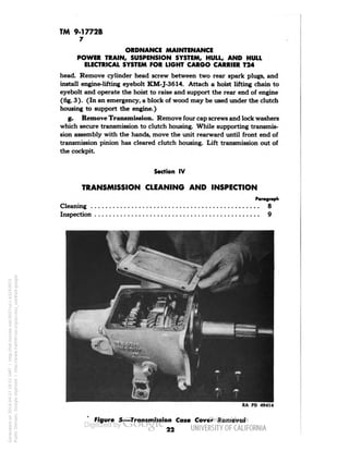
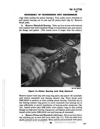
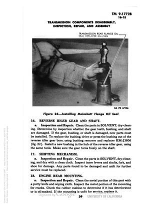
i "V 
TM 9-1772B 
WAR DEPARTMENT 
TECHNICAL MANUAL 
ORDNANCE MAINTENANCE 
POWER TRAIN, SUSPENSION SYSTEM, HULL, 
AND HULL ELECTRICAL SYSTEM FOR 
LIGHT CARGO CARRIER T24 
JULY 1, 1943 
TION CAN-CELLED, 
in accordance with , 
par. 15, A R 380-5, by author- fl 
ity of W.D. Circular 373 » 1 
Generated on 2014-04-27 18:37 GMT / http://hdl.handle.net/2027/uc1.b3243972 
Public Domain, Google-digitized / http://www.hathitrust.org/access_use#pd-google
Generated on 2014-04-27 18:38 GMT / http://hdl.handle.net/2027/uc1.b3243972 
Public Domain, Google-digitized / http://www.hathitrust.org/access_use#pd-google
(••D 
9-1772B 
RESTRICTE 
TECHNICAL MANUAL { 
No. 9-1772B f 
WAR DEPARTMENT 
Washington, 2 July 1943 
ORDNANCE MAINTENANCE 
POWER TRAIN, SUSPENSION SYSTEM, HULL, 
AND HULL ELECTRICAL SYSTEM FOR 
LIGHT CARGO CARRIER T24 
Prepared under the direction of the 
Chief of Ordnance 
(with the cooperation of the Studebaker Corporation) 
CONTENTS 
CHAPTER 1 INTRODUCTION 
CHAPTER 2 TRANSMISSION AND PROPELLER 
SHAFT WITH UNIVERSAL 
JOINTS 
SECTION I. Transmission description and 
data 
II. Transmission trouble shooting 
and test 
III. Transmission removal 
Paragraphs 
1-3 
4-42 
4-5 
6 
7 
Pages 
4-11 
12-60 
12-15 
16-19 
19-22 
IV. Transmission cleaning and 
inspection 
8-9 22-23 
Generated on 2014-04-27 18:38 GMT / http://hdl.handle.net/2027/uc1.b3243972 
Public Domain, Google-digitized / http://www.hathitrust.org/access_use#pd-google 
V. Disassembly of transmission 
into subassemblies 
VI. Cleaning of transmission parts. 
VII. Transmission components dis-assembly, 
inspection, repair, 
and assembly 
VIII. Assembly of transmission 
subassemblies _._... 
10 
11 
12-19 
20 
23-31 
31 
31-40 
40-44 
i Mo
TM 9-1772B 
ORDNANCE MAINTENANCE 
POWER TRAIN, SUSPENSION SYSTEM, HULL, AND HULL 
ELECTRICAL SYSTEM FOR LIGHT CARGO CARRIER T24 
Paragraphs Pages 
SECTION IX. Test transmission 21 44-45 
X. Installation and test of 
transmission 22 45-46 
XI. Transmission controls and 
linkage 23-29 46-50 
XII. Propeller shaft with universal 
joints 30-40 50-59 
XIII. Fits and tolerances 41-42 60 
CHAPTER 3 AXLE DIFFERENTIAL AND 
TRANSMISSION WITH FINAL 
DRIVES 43-83 61-126 
SECTION I. Description and data 43-44 61-63 
II. Trouble shooting 45-46 63-66 
III. Final drives removal 47 66-67 
IV. Final drives cleaning and 
inspection 48-49 68 
V. Disassembly of final drive 
assemblies 50 68-69 
VI. Cleaning of final drive parts... 51 70 
VII. Inspection and repair of final 
drive parts 52-55 70-72 
VIII. Assembly of final drives 56 72 
IX. Installation and test of final 
drives 57 72-73 
X.. Axle differential and transmis-sion 
removal 58 74 
XI. Axle differential and transmis-sion 
cleaning and inspection 59-60 74-75 
XII. Disassembly of axle differential 
and transmission 61 76-83 
XIII. Cleaning of axle differential and 
transmission components... 62 83 
XIV. Disassembly of axle differential 63 83-86 
XV. Axle differential components 
disassembly, inspection, 
repair, and assembly 64-69 86-94 
2 
Generated on 2014-04-27 18:38 GMT / http://hdl.handle.net/2027/uc1.b3243972 
Public Domain, Google-digitized / http://www.hathitrust.org/access_use#pd-google
TM 9-1772B 
CONTENTS 
Paragraphs 
Pages 
SECTION 
XVI. 
XVII. 
Assembly of axle differential . . 
70 
71-76 
95-99 
99-112 
Axle transmission components 
disassembly, inspection, 
repair, and assembly 
XVIII. 
XIX. 
XX. 
XXI. 
Assembly of axle differential 
and transmission components 
77 
113-119 
119-120 
Test and adjustment of axle 
differential and transmission 
78-79 
Installation and test of axle 
differential and transmission 
80 
81 
120-121 
121 
Fits and tolerances 
XXII. 
Axle differential and transmis-sion 
controls and linkage . . . 
82-83 
84-113 
Generated on 2014-04-27 18:38 GMT / http://hdl.handle.net/2027/uc1.b3243972 
Public Domain, Google-digitized / http://www.hathitrust.org/access_use#pd-google 
122-126 
127-160 
CHAPTER 4 
SUSPENSION SYSTEM, HULL, 
AND ATTACHMENTS 
SECTION 
t 
Description and data ... 
84-85 
127-128 
II. 
Suspension system trouble 
shooting and test 
86-87 
129-130 
III. 
Tracks 
88-92 
131-137 
IV. 
Front wheel and crank arm 
carrier 
93-97 
138-148 
V. 
Bogie wheel assembly and 
suspension 
98-108 
148-156 
VI. 
Guide wheel assembly
TM 9-1772B 
1-2 
ORDNANCE MAINTENANCE 
POWER TRAIN, SUSPENSION SYSTEM, HULL, AND HULL 
ELECTRICAL SYSTEM FOR LIGHT CARGO CARRIER T24 
CHAPTER 1 
INTRODUCTION 
Paragraph 
Scope 1 
Arrangement 2 
Maintenance allocation 3 
1. SCOPE. 
a. The instructions contained in this manual are for the information 
and guidance of personnel charged with the maintenance and repair of the 
Light Cargo Carrier T24. Information on the detailed construction of the 
unit, disassembly and assembly procedure, inspection, maintenance and 
repair, is contained in two Technical Manuals of the 1000 series, of which 
this is volume B. These instructions are supplementary to those in the 
Field and Technical Manuals prepared for the using arm. This manual 
does not contain information which is intended primarily for the using 
arm, since such information is available to ordnance maintenance person-nel 
in 100 series TM's or FM's. 
. b. This manual contains a description of, and procedure for, removal, 
disassembly, inspection and repair of the power train, suspension system, 
hull and hull electrical system. 
c. A description of, and procedure for, removal, disassembly, inspec-tion 
and repair of the engine, engine accessories and clutch is contained in 
TM 9-1772A. 
2. ARRANGEMENT. 
a. The subject matter contained in this manual is grouped by chapter, 
the scope of each being as indicated under "Contents." Because of the com-plexity 
and length, chapters have been devoted to the transmission and 
propeller shaft, axle differential and transmission with final drives, suspen-sion 
system and the hull and hull electrical system. Sections under various 
chapters are numbered consecutively within each chapter. Paragraphs are 
numbered consecutively throughout the manual. 
b. Illustrations of specific operations support and clarify the descrip-tive 
matter in the text. Exploded views of the component parts of units 
show the correct relation of related parts, and aid in identification. Figures 
are numbered consecutively throughout and are located as near as possible 
to the related text. Frequent references to applicable figures are made 
throughout the manual. 
4 
Generated on 2014-04-27 18:38 GMT / http://hdl.handle.net/2027/uc1.b3243972 
Public Domain, Google-digitized / http://www.hathitrust.org/access_use#pd-google
TM 
9-1772B 
2-3 
INTRODUCTION 
c. In this manual all references to units or parts as to right or left, and 
front or rear, are made on the basis of the driver's right, left, front and rear 
as he sits in the driver's seat facing ahead. 
3. MAINTENANCE ALLOCATION. 
a. Scope. The scope of maintenance and repair by the crew and other 
units of the using arms is determined by the availability of suitable tools, 
availability of necessary parts, capabilities of the mechanics, time avail-able, 
and tactical situation. All of these are variable and no exact system 
of procedure can be prescribed. 
b. Allocation of Maintenance. Indicated below are the maintenance 
duties for which tools and parts have been provided for the using arm per-sonnel. 
Other replacements and repairs are the responsibility of ordnance 
maintenance personnel but may be performed by using arm personnel 
when circumstances permit, within the discretion of the commander con-cerned. 
Echelons and words used in this list of maintenance allocations 
are denned as follows: 
SECOND ECHELON: 
THIRD ECHELON: 
FOURTH ECHELON: 
FIFTH ECHELON: 
SERVICE: 
(Including preventive 
maintenance) paragraph 
23 a (l)and(2) 
AR 850-15. 
REPLACE: 
Paragraph 23 a (4) 
AR 850-15. 
Line organization regiments, battalions, 
companies, detachments, and separate 
companies (first and second echelons). 
Ordnance light maintenance companies, 
ordnance medium maintenance com-panies, 
ordnance divisional maintenance 
battalions and ordnance post shops. 
Generated on 2014-04-27 18:38 GMT / http://hdl.handle.net/2027/uc1.b3243972 
Public Domain, Google-digitized / http://www.hathitrust.org/access_use#pd-google 
Ordnance heavy maintenance com-panies, 
and service command shops. 
Ordnance base regiments, ordnance 
bases, arsenals, and manufacturer's 
plants. 
Consists of servicing, cleaning, lubricat-ing, 
tightening bolts and nuts, and making 
external adjustment of subassemblies or 
assemblies and controls. 
Consists of removing the part, subassem-bly 
or assembly from the vehicles and 
replacing it with a new or reconditioned 
or rebuilt part, subassembly or assembly, 
whichever the case may be.
TM 9-1772B 
3 
ORDNANCE MAINTENANCE 
POWER TRAIN, SUSPENSION SYSTEM, HULL, AND HULL 
ELECTRICAL SYSTEM FOR LIGHT CARGO CARRIER T24 
REPAIR: Consists of making repairs to, or replace- 
Paragraph 23 a (3) ment of the part, subassembly or assern-and 
(5) in part. bly that can be accomplished without 
AR 850-15. completely disassembling the subassem-bly 
or assemblies, and does not require 
heavy welding, or riveting, machining, 
fitting and/or alining or balancing. 
REBUILD: Consists of completely reconditioning 
Paragraph 23 a (5) and replacing in serviceable condition 
in part and (6) any unserviceable part, subassembly, or 
AR 850-15. assembly of the vehicle, including weld-ing, 
riveting, machining, fitting, alining, 
balancing, assembling and testing. 
ECHELONS 
2nd 3rd 4th 5th 
CLUTCH 
Clutch—replace E X 
Clutch—repair X 
Clutch—rebuild E X 
Controls', and linkage—service and/or replace. ... X 
Controls and linkage—repair X 
Housing, clutch—replace X 
Housing, clutch—rebuild X 
COOLING GROUP 
Connections—replace X 
Radiator assembly—replace X 
Radiator assembly—repair X 
Radiator assembly—rebuild E X 
Shutter assembly•—replace X 
Shutter assembly—repair X 
System, cooling—service X 
*The second echelon is authorized to remove and reinstall items 
marked by an asterisk. However, when it is necessary to replace an item 
marked by an asterisk with a new or rebuilt part, subassembly or unit 
assembly, the assembly marked by an asterisk may be removed from the 
vehicle by the second echelon only after authority has been obtained 
from a higher echelon of maintenance. 
Operations allocated will normally be performed in the echelon indi-cated 
by "X." Operations allocated to the echelons as indicated by "E" 
may be accomplished by the respective echelons in emergencies only. 
6 
Generated on 2014-04-27 18:38 GMT / http://hdl.handle.net/2027/uc1.b3243972 
Public Domain, Google-digitized / http://www.hathitrust.org/access_use#pd-google
TM 9-1772B 
3 
INTRODUCTION 
ECHELONS 
2nd 3rd 4th 5th 
DIFFERENTIAL ASSEMBLY 
Band assemblies, brake—service X 
Band assemblies, brake—replace and/or repair 
(reline) X 
Controls and linkage—replace X 
Controls and linkage—repair X 
*Differential assembly—replace * X 
Differential assembly—repair X 
Differential assembly—rebuild E X 
DRIVE, FINAL 
Bearings, sprocket wheel—service and/or replace X 
Drive assembly, final—replace X 
Drive assembly, final—repair X 
Drive assembly, final—rebuild E X 
Hub assemblies—replace X 
Hub assemblies—repair X 
Hub assemblies—rebuild E X 
Retainers, sprocket wheel grease—replace X 
Shaft, axle—replace X 
Sprocket and wheel assemblies—replace X 
Sprocket and wheel assemblies—repair X 
Sprocket and wheel assemblies—rebuild E X 
ELECTRICAL GROUP 
Battery—service, recharge and/or replace X 
Battery—repair X 
Battery—rebuild E X 
Box, junction—replace X 
Coil, ignition—replace X 
Conduits and wiring—replace and/or repair X 
Defroster assembly—replace X 
Lamp assemblies—service and/or replace X 
Lamp assemblies—repair X 
Regulator, current and voltage—replace X 
Regulator, current and voltage—service and/or 
Generated on 2014-04-27 18:38 GMT / http://hdl.handle.net/2027/uc1.b3243972 
Public Domain, Google-digitized / http://www.hathitrust.org/access_use#pd-google 
repair X 
Regulator, current and voltage—rebuild X 
Switch assemblies—replace X 
Switch assemblies—repair X 
*Sce notes on page 6.
TM 9-1772B 
3 
ORDNANCE MAINTENANCE 
POWER TRAIN, SUSPENSION SYSTEM, HULL, AND HULL 
ELECTRICAL SYSTEM FOR LIGHT CARGO CARRIER T24 
ECHELONS 
2nd 3rd 4th 5th 
ENGINE 
Bearings, crankshaft (inserts)—replace E E X 
Belt—service and/or replace X 
Block, cylinder—rebuild (recondition) E X 
Carburetor assembly—replace X 
Carburetor assembly—repair X 
Carburetor assembly—rebuild X 
Cleaner, air—service and/or replace X 
Cleaner, air—repair X 
Condenser, distributor—replace X 
Controls and linkage—service and/or replace.... X 
Controls and linkage—repair X 
Crankshaft—rebuild (recondition) E X 
Distributor assembly—service and/or replace... X 
Distributor assembly—repair X 
Distributor assembly—rebuild X 
*Engine assembly—replace * X 
Engine assembly—repair X 
Engine assembly—rebuild E X 
Fan assembly—replace X 
Fan assembly—repair X 
Fan assembly—rebuild X 
Filter assembly, oil—service and replace cartridge X 
Filter assembly, oil—repair X 
Flywheel—replace and/or repair X 
Flywheel—rebuild (recondition) E X 
Gaskets, cylinder head and manifold—replace ... X 
Gear train, timing—replace X 
Generator assembly—replace X 
Generator assembly—repair X 
Generator assembly—rebuild X 
Head, cylinder—replace and/or repair X 
Generated on 2014-04-27 18:39 GMT / http://hdl.handle.net/2027/uc1.b3243972 
Public Domain, Google-digitized / http://www.hathitrust.org/access_use#pd-google 
Lines and connections, oil (external)—replace ... X 
Lines and connections, oil (external)—repair .... X 
Lines and connections, oil (internal) — replace 
and/or repair X 
Manifolds—replace X 
Manifolds—repair X 
*See notes on page 6.
TM 9-1772B 
3 
INTRODUCTION 
ECHELONS 
2nd 3rd 4th 5th 
ENGINE (Cont'd) 
Motor assembly, starting—replace and/or repair X 
Motor assembly, starting—rebuild X 
Pan assembly, oil—service and replace gaskets .. X 
Pan assembly, oil—repair and/or replace X 
Pistons and rings—replace E E X 
Plugs, spark-i-service and/or replace X 
Plugs, spark (two-piece)—repair X 
Points, breaker, distributor—replace X 
Pump assembly, fuel—replace and/or repair X 
Pump assembly, fuel—rebuild X 
Pump assembly—oil—replace and/or repair X 
Pump assembly, oil—rebuild X 
Pump assembly, water—replace X 
Pump assembly, water—repair X 
Pump assembly, water—rebuild X 
Rods, connecting—replace E E X 
Thermostat—replace X 
Valves—service X 
Ventilator, crankcase—service and/or replace ... X 
Wiring, ignition—replace X 
EXHAUST GROUP 
Muffler and exhaust pipes—replace. . .v X 
EXTINGUISHER, FIRE 
Extinguisher, fire (carbon tetrachloride CC14) 
service (refill) and/or replace X 
Extinguisher, fire (carbon tetrachloride CC14) 
—repair X 
Extinguisher, fire (carbon tetrachloride CC14) 
—rebuild E X 
FUEL GROUP 
Filter assembly, fuel—service and/or replace.... X 
Filter assembly, fuel—repair X 
Lines and connections—replace X 
Generated on 2014-04-27 18:39 GMT / http://hdl.handle.net/2027/uc1.b3243972 
Public Domain, Google-digitized / http://www.hathitrust.org/access_use#pd-google 
Lines and connections—repair E X 
Pump assembly, primer—replace X 
Pump assembly, primer—repair X 
See notes on page 6.
TM 9-1772B 
3 
ORDNANCE MAINTENANCE 
POWER TRAIN, SUSPENSION SYSTEM, HULL, AND HULL 
ELECTRICAL SYSTEM FOR LIGHT CARGO CARRIER T24 
ECHELONS 
2nd 3rd 4th 5th 
FUEL GROUP (Cont'd) 
Pump assembly, primer—rebuild X 
Tank, service and/or replace X 
Tank—repair X 
HULL 
Bows—replace X 
Bows—repair X 
Hull—repair X 
Hull—rebuild E X 
Pintle assembly—replace X 
Pintle assembly—repair X 
Pintle assembly—rebuild X 
Seats—replace X 
Seats—repair X 
Tarpaulin—replace X 
Tarpaulin—repair E X 
Windshield assembly—replace X 
Windshield assembly—repair X 
Wiper assemblies, windshield—replace X 
Wiper assemblies, windshield—repair E X 
Wiper assemblies, windshield—rebuild X 
INSTRUMENTS 
Instruments—replace X 
Instruments—repair X 
Instruments—rebuild E X 
SHAFTS, PROPELLER 
Shaft assemblies, propeller (w/universal joints) 
—replace X 
Shaft assemblies, propeller (w/universal joints) 
—repair X 
Shaft assemblies, propeller (w/universal joints) 
—rebuild E X 
SUSPENSION GROUP 
Arm, idler—replace X 
Arm, idler—repair X 
Arm, idler—rebuild E X 
See notes on page 6. 
10 
Generated on 2014-04-27 18:39 GMT / http://hdl.handle.net/2027/uc1.b3243972 
Public Domain, Google-digitized / http://www.hathitrust.org/access_use#pd-google
TM 9-1772B 
3 
INTRODUCTION 
ECHELONS 
2nd 3rd 4th 5th 
SUSPENSION GROUP (Cont'd) 
Arm, idler support—replace : X 
Arm, idler support—repair X 
Arm, idler support—rebuild E X 
Bearings, idler wheel—service and/or replace. ... X 
Bogie, components—replace . X 
Bogie, components—repair X 
Bogie, components—rebuild E X 
Retainers, idler wheel grease—replace X 
Roller assemblies, track support—replace X 
Roller assemblies, track support—repair X 
Roller assemblies, track support—rebuild E X 
Spring assemblies, suspension—replace X 
Spring assemblies, suspension—repair X 
Spring assemblies, suspension—rebuild E X 
Track assemblies—replace X 
Track assemblies—repair X 
Wheel assemblies—replace X 
Wheel assemblies—repair X 
Wheel assemblies—rebuild E X 
TRANSMISSION 
Controls and linkage—service and/or replace.... X 
Controls and linkage—repair X 
*Transmission assembly—replace * X 
Transmission assembly—repair X 
Transmission assembly—rebuild E X 
VEHICLE ASSEMBLY 
Carrier assembly—service X 
Carrier assembly—rebuild (with serviceable unit 
assemblies) X E 
*See notes on page 6. 
11 
Generated on 2014-04-27 18:39 GMT / http://hdl.handle.net/2027/uc1.b3243972 
Public Domain, Google-digitized / http://www.hathitrust.org/access_use#pd-google
TM 9-1772B 
4 
ORDNANCE MAINTENANCE 
POWER TRAIN, SUSPENSION SYSTEM, HULL, AND HULL 
ELECTRICAL SYSTEM FOR LIGHT CARGO CARRIER T24 
CHAPTER 2 
TRANSMISSION AND PROPELLER SHAFT WITH 
UNIVERSAL JOINTS 
Section I 
TRANSMISSION DESCRIPTION AND DATA 
Paragraph 
Description and operation 4 
Data 5 
4. DESCRIPTION AND OPERATION. 
a. The function of the transmission unit is to provide a means of trans-ferring 
engine torque to the vehicle driving tracks at variable engine and 
track speed ratios. The several transmission gears, operating shafts, shift-ing 
mechanism, and bearings are contained in a cast-iron case having a 
lubricant filler plug and a drain plug. A cover plate is located on the top 
of the case, a mainshaft flange at the rear, and a pinion flange at the front. 
Two shift levers are mounted externally on the left side of the transmis-sion 
case. 
b. The transmission has three forward speeds and one reverse. Power 
enters at the front end of the transmission through the transmission pinion 
from the clutch driven member, the hub of which is carried on the pinion 
shaft splines. The pinion is supported at its rear end by a ball bearing 
and at the front by a bushing in the flywheel hub. Just inside the front 
wall of the transmission case the power is transmitted to the transmission 
countershaft cluster gear. The cluster is carried on bronze bushings that 
bear on the countershaft which is locked stationary in the case. The 
countershaft gear cluster and the transmission pinion are in motion at all 
times when the engine is operating and the clutch is engaged (fig. 2). 
c. A splined mainshaft, a synchronizer unit, and a sliding gear, to-gether 
with two shifting forks and mechanism, complete the transmission 
unit. The mainshaft is supported at the rear by a ball bearing, while the 
front end turns on bearing rollers recessed in the rearward end of the 
pinion. Movement of either the synchronizer or the sliding gear is con-trolled 
by the transmission remote control shift lever located at the front 
of the cockpit immediately ahead of the driver's seat. The position of the 
synchronizer or sliding gear can be changed by moving the control lever 
and linkage to engage the first speed combination, second or third speed 
gearing, or the reverse gear combination. When the shift to high gear 
12 
Generated on 2014-04-27 18:39 GMT / http://hdl.handle.net/2027/uc1.b3243972 
Public Domain, Google-digitized / http://www.hathitrust.org/access_use#pd-google
TM 9-1772B 
4 
TRANSMISSION DESCRIPTION AND DATA 
13 
Generated on 2014-04-27 18:39 GMT / http://hdl.handle.net/2027/uc1.b3243972 
Public Domain, Google-digitized / http://www.hathitrust.org/access_use#pd-google
TM 9-1772B 
4 
ORDNANCE MAINTENANCE 
POWER TRAIN, SUSPENSION SYSTEM, HULL, AND HULL 
ELECTRICAL SYSTEM FOR LIGHT CARGO CARRIER T24 
£ 
2 
14 
Generated on 2014-04-27 18:39 GMT / http://hdl.handle.net/2027/uc1.b3243972 
Public Domain, Google-digitized / http://www.hathitrust.org/access_use#pd-google
TM 9-1772B 
4-5 
TRANSMISSION DESCRIPTION AND DATA 
(third speed) is made, the synchronizer moves to the front to engage the 
small spur teeth of the pinion. The drive through the countershaft gears 
is eliminated entirely in this position because the mainshaft is connected 
directly with the engine clutch. 
d. The second and high gear combination is fitted with synchronizing 
rings to permit shifting between second and high, or vice versa, without 
gear tooth interference. The reverse direction of motion is accomplished 
through an idler gear engaged with the small gear of the cluster. The 
sliding gear engages with the idler gear when a shift is made into reverse. 
The idler gear turns on a bronze bushing in its hub. 
e. The splined rearward end of the mainshaft is connected to the 
propeller shaft through a ground and splined sleeve or slip joint with 
yoke, which is free to move ahead or rearward as required, due to the 
movement of the cushion-mounted engine. The outer ground surface of 
the slip joint bears against a spring-loaded leather seal to prevent the 
escape of oil at the rearward end of the transmission case. 
5. DATA. 
Make Warner 
Model T-84-J 
Type Synchromesh 
Speeds 3 forward, 1 reverse 
Helical gears. 2nd speed and constant mesh 
Synchronizers 2nd and high speeds 
Ratios: 
1st 2.66 
2nd 1.56 
3rd 1 to 1 
Reverse 3.55 
Pinion bearing: 
Type Ball 
Manufacturer's Number MRC-207SFG or 
SKF-6207-ZN 
Bore 1.3775-in. 
Outside Diameter 2.8340-in. 
Width 0.6643-in. 
Mainshaft front bearing: 
Type Ball 
Manufacturer's Number MRC-206SFG or 
SKF-6206-ZN 
15 
Generated on 2014-04-27 18:39 GMT / http://hdl.handle.net/2027/uc1.b3243972 
Public Domain, Google-digitized / http://www.hathitrust.org/access_use#pd-google
TM 9-1772B 
6 
ORDNANCE MAINTENANCE 
POWER TRAIN, SUSPENSION SYSTEM, HULL, AND HULL 
ELECTRICAL SYSTEM FOR LIGHT CARGO CARRIER T24 
Section II 
TRANSMISSION TROUBLE SHOOTING AND TEST 
Paragraph 
Trouble shooting 6 
6. TROUBLE SHOOTING, 
a. Noisy in Neutral. 
Possible Cause 
Misalinement of transmission with 
engine assembly. 
Transmission pinion bearing rough, 
damaged, or dirty. 
Transmission constant mesh gears 
scuffed, chipped, butted or im-properly 
machined. 
Transmission countershaft bush-ings 
scored, dirty, or rough. 
Transmission mainshaft second 
speed gear bushing rough, scored, 
or damaged. 
Transmission constant mesh gears 
not properly meshed. 
Reverse idler gear shaft or bushing 
rough, scored, or damaged. 
Reverse idler gear, scuffed, chipped, 
burred, or improperly machined. 
Eccentric second speed constant 
mesh gear. 
Too much lash in constant mesh 
gear train. 
Abnormal end play of countershaft 
gear cluster, reverse idler gear, 
or pinion. 
Transmission mainshaft pilot bear-ing 
rollers badly damaged or 
broken. 
Insufficient lubricant in transmis-sion. 
Incorrect grade or dirty transmis-sion 
lubricant. 
Possible Remedy 
Aline clutch housing to engine front 
plate and aline transmission to 
clutch housing. 
Clean or replace as required. 
Replace as required. 
Clean or replace as required. 
Clean or replace mainshaft with 
gears assembly. 
Replace with a complete set. 
Replace as required. 
Replace. 
Replace mainshaft with gears as-sembly. 
Replace parts as required. 
Replace. 
Fill to recommended level. 
Drain, flush transmission, and re-place 
lubricant. 
16 
Generated on 2014-04-27 18:50 GMT / http://hdl.handle.net/2027/uc1.b3243972 
Public Domain, Google-digitized / http://www.hathitrust.org/access_use#pd-google
TM 9-1772B 
6 
TRANSMISSION TROUBLE SHOOTING AND TEST 
b. Noisy in Gear. 
Possible Cause 
Transmission mainshaft front bear-ing 
rough, damaged, or dirty. 
Transmission sliding gear teeth 
rough, burred, scuffed, pitted, 
chipped, or tapered. 
Excessive clearance or end play of 
mainshaft second speed gear on 
mainshaft. 
c. Oil Leaks. 
Lubricant level too high in trans-mission 
case. 
Damaged, improperly installed, or 
missing gaskets. 
Damaged or improperly installed 
oil seals. 
Transmission case drain or filler 
plug loose or threads damaged. 
Transmission case bolts loose, miss-ing, 
or threads stripped. 
Sand hole or crack in transmission 
case. 
Use of a lubricant which foams ex-cessively. 
d. Difficult to Shift into Gear. 
Failure to completely disengage 
clutch. 
Synchronizer sleeve fits too tightly 
on synchronizer gear. 
Insufficient chamfer on sliding gear 
teeth. 
Mainshaft splines distorted, butted, 
or damaged. 
Sliding gear tight on mainshaft 
splines. 
Improper adjustment or bent re-mote 
control linkage. 
Lubricant too heavy or cold. 
Possible Remedy 
Clean or replace as required. 
Replace mainshaft with gears as-sembly. 
Drain to proper level. 
Replace or install properly as re-quired. 
Replace or reinstall as required. 
Tighten or replace plug as neces-sary. 
Tighten or replace bolts. 
Replace transmission case. 
Drain, flush, and refill transmission 
with recommended lubricant. 
Inspect clutch pedal and linkage for 
freedom and maximum travel, or 
correct faulty shifting habit. 
Replace synchronizer assembly. 
Replace mainshaft with gears as-sembly. 
Replace mainshaft assembly. 
Free members or replace mainshaft 
with gears assembly as required. 
Adjust, reform, replace as required. 
Change to proper grade. 
17 
Generated on 2014-04-27 18:50 GMT / http://hdl.handle.net/2027/uc1.b3243972 
Public Domain, Google-digitized / http://www.hathitrust.org/access_use#pd-google
VM 9-1772B 
6 
ORDNANCE MAINTENANCE 
POWER TRAIN, SUSPENSION SYSTEM, HULL, AND HULL 
ELECTRICAL SYSTEM FOR LIGHT CARGO CARRIER T24 
e. Sticks in Gear. 
Possible Cause 
Engine clutch not completely dis-engaged. 
Insufficient chamfer at edge of 
gearshift lever cam poppet ball 
notches. 
Sliding gear tight on mainshaft. 
Distorted, butted, or damaged 
mainshaft splines. 
Improper adjustment or bent re-mote 
control linkage. 
f. Slips Out of High Gear. 
Misalinement of transmission with 
engine. 
Transmission pinion gear teeth 
tapered. 
Synchronizer sleeve or ring teeth 
damaged or tapered. 
Insufficient poppet spring tension 
on gearshift lever cam notch. 
Excessive chamfer on edge of gear-shift 
lever cam notches. 
Improper adjustment or bent re-mote 
control linkage. 
Abnormal end play of second speed 
constant mesh on mainshaft. 
Synchronizer sleeve or ring teeth 
tapered, or distorted. 
Excessive chamfer on edge of gear-shift 
lever cam notch. 
Improper adjustment of remote 
control rods. 
Possible Remedy 
Generated on 2014-04-27 18:50 GMT / http://hdl.handle.net/2027/uc1.b3243972 
Public Domain, Google-digitized / http://www.hathitrust.org/access_use#pd-google 
Check clutch adjustment and re-lease 
mechanism. 
Replace parts as required. 
Free or replace mainshaft with 
gears assembly. 
Replace mainshaft with gears as-sembly. 
Adjust, reform, or replace as re-quired. 
Aline clutch housing to engine 
front plate and transmission to 
clutch housing as required. 
Replace pinion. 
Replace synchronizer assembly. 
Replace poppet. 
Replace shift lever. 
Adjust, reform, or replace parts in-volved. 
Replace parts as required. 
Replace synchronizer assembly. 
Replace shift lever. 
Adjust, reform, or replace parts in-volved. 
g. Slips Out of First and Reverse Gear. 
First and reverse sliding gear loose 
on mainshaft splines. 
First and reverse sliding gear teeth 
damaged or tapered. 
Mainshaft splines distorted. 
Replace mainshaft with gears as-sembly.
TM 9-1772B 
6-7 
TRANSMISSION TROUBLE SHOOTING AND TEST 
Possible Cause Possible Remedy 
Countershaft first speed gear teeth Replace gear cluster. 
damaged or tapered. 
Excessive end play of countershaft Replace parts as required. 
gear cluster. 
Reverse idler gear teeth damaged Replace gear. 
or tapered. 
Excessive end play of reverse idler Replace parts as required. 
gear in transmission case. 
Too much chamfer on edge of gear- Replace shift lever. 
shift lever cam notch. 
Gearshift lever cam notch not ma- Replace shift lever. 
chined sufficiently deep. 
Improper adjustment of remote Adjust, reform, or replace parts in-control 
rods. volved. 
Transmission locks in two gears See "Note." 
at once. 
NOTE: Where operating difficulties involve the remote control shift 
rods and linkage, the adjustment and rate of wear on the engine mount-ings 
affect the relative position of the engine to permit movement which 
may change the control linkage adjustment. 
h. Diagnosis. Most noises emanating from the transmission will not 
be audible with the vehicle in motion because of the various other oper-ating 
noises. However, a preliminary operating check on the transmission 
may be obtained by first disengaging the axle unit (axle transmission 
shift lever in neutral). With the engine running, shift the transmission 
into low, second, high, and reverse gears respectively. In each position, 
run the engine at various speeds and listen carefully for unusual noises. 
It is possible that the investigation will disclose a noise caused by another 
part of the drive line; such as from worn universal joint needle bearings, 
loose universal joints, a bent or otherwise misalined propeller shaft, or 
a faulty clutch. 
Section III 
TRANSMISSION REMOVAL 
Paragraph 
Remove transmission 7 
7. REMOVE TRANSMISSION. 
a. Remove Top. Refer to paragraph 117. 
b. Remove Engine Compartment Lid. Unscrew two large wing nuts 
holding engine compartment lid to side panel, and move lid up until 
19 
Generated on 2014-04-27 18:50 GMT / http://hdl.handle.net/2027/uc1.b3243972 
Public Domain, Google-digitized / http://www.hathitrust.org/access_use#pd-google
TM 9-1772B 
7 
ORDNANCE MAINTENANCE 
POWER TRAIN, SUSPENSION SYSTEM, HULL, AND HULL 
ELECTRICAL SYSTEM FOR LIGHT CARGO CARRIER T24 
ENGINE LIFTING EYE BOLT KM-J36I4 
RA PD 67038 
Figure 3—Supporting Rear of Engine 
20 
Generated on 2014-04-27 18:50 GMT / http://hdl.handle.net/2027/uc1.b3243972 
Public Domain, Google-digitized / http://www.hathitrust.org/access_use#pd-google
TM 9-1772B 
7 
TRANSMISSION REMOVAL 
RA PD 67047 
Figure 4—Transmission Removal 
engaging tongues can be removed from slots in hull coaming on right side. 
Lift lid from vehicle. 
c. Remove Hull Floor Pan. Take out cap screws holding floor pan 
to hull, and remove pan. 
d. Remove Propeller Shaft. Refer to paragraph 34. 
e. Disconnect Transmission. Remove two screws securing engine 
rear (transmission) support mounting to the hull cross member. Discon-nect 
remote control linkage at the transmission by removing cotter pins 
and clevis pins. 
f. Support Rear of Engine. Remove hull drain plate and drain cool-ing 
system sufficiently to bring the solution level below top of cylinder 
21 
Generated on 2014-04-27 18:50 GMT / http://hdl.handle.net/2027/uc1.b3243972 
Public Domain, Google-digitized / http://www.hathitrust.org/access_use#pd-google
TM 9-1772B 
7 
ORDNANCE MAINTENANCE 
POWER TRAIN, SUSPENSION SYSTEM, HULL, AND HULL 
ELECTRICAL SYSTEM FOR LIGHT CARGO CARRIER T24 
head. Remove cylinder head screw between two rear spark plugs, and 
install engine-lifting eyebolt KM-J-3614. Attach a hoist lifting chain to 
eyebolt and operate the hoist to raise and support the rear end of engine 
(fig. 3 ). (In an emergency, a block of wood may be used under the clutch 
housing to support the engine.) 
g. Remove Transmission. Remove four cap screws and lock washers 
which secure transmission to clutch housing. While supporting transmis-sion 
assembly with the hands, move the unit rearward until front end of 
transmission pinion has cleared clutch housing. Lift transmission out of 
the cockpit 
. 
Section IV 
TRANSMISSION CLEANING AND INSPECTION 
Paragraph 
Cleaning 8 
Inspection 9 
RA PD 494T4 
Figure 5—Transmission Case Cover Removal 
22 
Generated on 2014-04-27 18:51 GMT / http://hdl.handle.net/2027/uc1.b3243972 
Public Domain, Google-digitized / http://www.hathitrust.org/access_use#pd-google
TM 
9-1772B 
TRANSMISSION CLEANING AND INSPECTION 
8-9 
8. CLEANING. 
a. Apply SOLVENT, dry-cleaning, with a brush or cloth to soak off 
any lubricant, dirt, or foreign matter that may have accumulated on the 
exterior of the case and flanges. Dry all surfaces with wiping cloths or by 
using compressed air. 
9. INSPECTION. 
a. Remove the transmission case drain plug and drain out the lubri-cant. 
Carefully examine the outside of the transmission case, pinion 
flange, and mainshaft flange for cracks, oil seepage, or other external dam-age. 
Remove the four transmission case cover cap screws, internal lock 
washers, and lift the cover and gasket off the case (fig. 5). Inspect the 
internal transmission parts to detect any evidence of damaged gears, 
shafts, synchronizers, or shifting mechanism. 
Section V 
DISASSEMBLY OF TRANSMISSION 
INTO SUBASSEMBLIES 
Disassembly 
Paragraph 
10 
RA PD 66966 
Figure 6—Pinion Flange Removal 
23 
Generated on 2014-04-27 18:51 GMT / http://hdl.handle.net/2027/uc1.b3243972 
Public Domain, Google-digitized / http://www.hathitrust.org/access_use#pd-google
TM 9-1772B 
1G 
ORDNANCE MAINTENANCE 
POWER TRAIN, SUSPENSION SYSTEM, HULL, AND HULL 
ELECTRICAL SYSTEM FOR LIGHT CARGO CARRIER T24 
Figure 7- 
RA PD 66969 
'inion Bearing Retainer Ring Removal 
10. DISASSEMBLY. 
a. Remove Pinion Bearing. Place the transmission assembly in a 
vise and remove the three pinion flange screws and internal lock washers. 
Slip pinion flange and gasket off pinion shaft (fig. 6). Slide the cork seal 
off pinion shaft. Remove pinion bearing large retainer ring (fig. 7). Re-move 
pinion bearing small lock ring using snap ring pliers (fig. 8). Install 
puller plate KM-J3641 less adapter rings, so that pulling flanges on the 
plate enter retainer ring groove in pinion bearing. Tighten puller plate 
screws. Install utility puller KM-J3635 so that end of the puller screw 
bears against front end of pinion shaft. Install thrust yoke KM-J3643 
with thinner side of yoke in groove in pinion gear. The thick side of the 
yoke will bear against the front face of the mainshaft second speed gear. 
(The thrust yoke must be used to prevent damaging the synchronizer 
—^ 24 
Generated on 2014-04-27 18:51 GMT / http://hdl.handle.net/2027/uc1.b3243972 
Public Domain, Google-digitized / http://www.hathitrust.org/access_use#pd-google
TM 9-1772B 
10 
DISASSEMBLY OF TRANSMISSION INTO SUBASSEMBLIES 
rings when pulling the pinion bearing.) Turn puller screw clockwise to 
pull pinion bearing out of case and off pinion shaft (fig. 9). Remove 
thrust yoke. 
b. Remove Mainshaft Bearing. Take out four screws with internal 
lock washers that hold mainshaft flange to transmission case, and remove 
the flange and gasket. (The lowest screw is longer than the others.) 
RA PD 49418 
Figure 8—Pinion Bearing Lock Ring Removal 
Remove spacer lock ring with snap ring pliers, slip spacer off mainshaft, 
and remove mainshaft rear bearing retainer ring. Place thrust yoke 
KM-J3643 in position as when pulling pinion bearing. Carefully pry in 
the bearing retainer ring groove to move mainshaft rear bearing out of 
case sufficiently to permit installation of bearing puller equipment (fig. 
10). Install puller plate KM-J3641 with adapter rings so that pulling 
flanges on rings enter bearing ring groove, and tighten puller plate screws. 
Install utility puller KM-J3635 and pull bearing off mainshaft. 
c. Remove Pinion and Mainshaft with Gears. Drive out from below 
the retaining pin at each shift lever shaft (fig. 11). Pull two shift lever 
shafts outward as far as possible. Move pinion and mainshaft with gears 
25 
Generated on 2014-04-27 18:51 GMT / http://hdl.handle.net/2027/uc1.b3243972 
Public Domain, Google-digitized / http://www.hathitrust.org/access_use#pd-google
TM 9-1772B 
10 
ORDNANCE MAINTENANCE 
POWER TRAIN, SUSPENSION SYSTEM, HULL, AND HULL 
ELECTRICAL SYSTEM FOR LIGHT CARGO CARRIER T24 
UNIVERSAL' PULLER KM-J3635—> ^—THRUST YOKE KM-J3643 
REMOVER KM-J364I 
RA PD 49417 
Figure 9—Method of Removing Pinion Bearing 
away from shift fork and shoe, and move shift fork and shoe out of the 
way. Tilt the mainshaft slightly and pull pinion shaft away from end of 
mainshaft (fig. 12 ) and out from the front of the case (fig. 13 ). Lift main-shaft 
with gears and synchronizer upward and out through top of case 
(fig. 14). Remove shift fork and shoe from shift lever shafts. 
d. Remove Countershaft and Gear Cluster. Remove countershaft 
and reverse idler gear shaft lock plate. Drive countershaft out rear of 
transmission case (fig. 15). Lift cluster gear out through the top of case. 
Note that the thrust washer at the front of the gear cluster (largest gear) 
has an ear which must be toward the case so that the washer will not turn 
with the cluster. Two thrust washers are used at the other end of the 
cluster. The washer with the small hole must be next to the case so small 
hole will fit over pin in case to hold it stationary. Between this rear thrust 
washer and the cluster is a thrust washer with ears that engage between 
teeth of small gear at rear so that it turns with the cluster. 
e. Remove Reverse Idler Gear Shaft and Gear. Remove reverse 
idler gear shaft from transmission case, driving on the front end of the 
shaft if necessary. The reverse idler gear may be lifted out of the case 
as the shaft is removed. Note that gear hub extension is toward the front. 
26 
Generated on 2014-04-27 18:52 GMT / http://hdl.handle.net/2027/uc1.b3243972 
Public Domain, Google-digitized / http://www.hathitrust.org/access_use#pd-google
TM 9-1772B 
10 
DISASSEMBLY OF TRANSMISSION INTO SUBASSEMBLIES 
THRUST YOKE KM-J3643 
RA PD 49420 
Figure 10—Mainshaft Rear Bearing Initial Removal 
27 
Generated on 2014-04-27 18:52 GMT / http://hdl.handle.net/2027/uc1.b3243972 
Public Domain, Google-digitized / http://www.hathitrust.org/access_use#pd-google
TM 9-1772B 
10 
ORDNANCE MAINTENANCE 
POWER TRAIN, SUSPENSION SYSTEM, HULL, AND HULL 
ELECTRICAL SYSTEM FOR LIGHT CARGO CARRIER T24 
RA PD 66977 
Figure 11—Shift Lever Shaft Pins Removal 
RA PD 66978 
Figure 12—Separating Pinion and Mainshaft Assemblies 
28 
Generated on 2014-04-27 18:52 GMT / http://hdl.handle.net/2027/uc1.b3243972 
Public Domain, Google-digitized / http://www.hathitrust.org/access_use#pd-google
TM 9-1772B 
10 
DISASSEMBLY OF TRANSMISSION INTO SUBASSEMBLIES 
RA PD 
Figure 13 — Pinion Assembly Removal 
RA PD 
Figure 14 — Malnshaft Assembly Removal 
29 
Generated on 2014-04-27 18:52 GMT / http://hdl.handle.net/2027/uc1.b3243972 
Public Domain, Google-digitized / http://www.hathitrust.org/access_use#pd-google
TM 9-1772B 
10 
ORDNANCE MAINTENANCE 
POWER TRAIN, SUSPENSION SYSTEM, HULL, AND HULL 
ELECTRICAL SYSTEM FOR LIGHT CARGO CARRIER T24 
RA PD 66986 
Figure 15—Countershaft Removal 
RA PD 66991 
figure 16—Shift Lever Shaft Removal 
30 
Generated on 2014-04-27 18:52 GMT / http://hdl.handle.net/2027/uc1.b3243972 
Public Domain, Google-digitized / http://www.hathitrust.org/access_use#pd-google
TM 9-1772B 
10-12 
DISASSEMBLY OF TRANSMISSION INTO SUBASSEMBLIES 
f. Remove Shift Levers and Shafts. Remove nut, lock washer, and 
flat washer that holds outer shift lever to shift shaft. Remove outer shift 
lever, cork seal, and lift shift lever shaft out of hole in the side of the case 
and out the top of the transmission case (fig. 16). Remove shift levers 
poppet from recess in side of case. Repeat the operations to remove the 
other shift lever and shaft. 
g. Remove Engine Rear Mounting from Transmission Case. Re-move 
the two cap screws and lock washers holding flexible engine front 
mounting with bracket to bottom of transmission. 
Section VI 
CLEANING OF TRANSMISSION PARTS 
Paragraph 
Cleaning 11 
11. CLEANING. 
a. Clean all parts and subassemblies carefully in SOLVENT, dry-cleaning, 
and blow them dry with compressed air. Dislodge any solid par-ticles 
that remain in the ball bearings by tapping them sharply on a block 
of wood. Immerse the bearings in cleaning solvent again and wash them 
to remove all traces of oil or dirt. Blow dry with compressed air, being 
careful not to direct the air at the side or face of the bearings to avoid 
spinning. 
Section VII 
TRANSMISSION COMPONENTS DISASSEMBLY, 
INSPECTION, REPAIR, AND ASSEMBLY 
Paragraph 
General 12 
Pinion and bearings 13 
Mainshaft and parts 14 
Countershaft and gear cluster 15 
Reverse idler gear and shaft 16 
Shifting mechanism 17 
Engine rear mounting 18 
Case and flanges 19 
12. GENERAL. 
a. The disassembly, cleaning, inspection, repair, and assembling of the 
various subassemblies must be performed with care and cleanliness. To 
31 
Generated on 2014-04-27 18:52 GMT / http://hdl.handle.net/2027/uc1.b3243972 
Public Domain, Google-digitized / http://www.hathitrust.org/access_use#pd-google
TM 9-1772B 
12 
ORDNANCE MAINTENANCE 
POWER TRAIN, SUSPENSION SYSTEM, HULL, AND HULL 
ELECTRICAL SYSTEM FOR LIGHT CARGO CARRIER T24 
Generated on 2014-04-27 18:53 GMT / http://hdl.handle.net/2027/uc1.b3243972 
Public Domain, Google-digitized / http://www.hathitrust.org/access_use#pd-google
TM 9-1772B 
12-13 
TRANSMISSION COMPONENTS DISASSEMBLY, 
INSPECTION, REPAIR, AND ASSEMBLY 
RA PD 49425 
Figure IB—Pinion Bearing Rollers Lock Ring Removal 
avoid confusion or error, each subassembly must be treated as a unit. 
Mark certain related parts before disassembly, to aid in subsequent 
assembly operations. Carefully clean each component after disassembly. 
The various parts must be inspected carefully and thoroughly to deter-mine 
their fitness for further service. 
13. PINION AND BEARINGS. 
a. Disassembly. Lift synchronizer ring off gear end of pinion. Hold 
pinion assembly in a vise having copper or other soft metal inserts for the 
jaws. Remove bearing roller lock ring from groove in pinion recess, using 
a thin narrow blade screwdriver and a 4-inch blade screwdriver (fig. 18). 
Remove the 13 bearing rollers. 
b. Inspection and Repair. Clean all parts in SOLVENT, dry-clean-ing. 
Inspect ball bearing and bearing rollers for galling or damage. In- 
33 
Generated on 2014-04-27 19:03 GMT / http://hdl.handle.net/2027/uc1.b3243972 
Public Domain, Google-digitized / http://www.hathitrust.org/access_use#pd-google
TM 9-1772B 
13 ORDNANCE MAINTENANCE 
POWER TRAIN, SUSPENSION SYSTEM, HULL, AND HULL 
ELECTRICAL SYSTEM FOR LIGHT CARGO CARRIER T24 
HA PD 49439 
Figure 19—Synchronizer, Second Speed Gear, and 
Low and Reverse Sliding Gear Removal 
34 
Generated on 2014-04-27 19:03 GMT / http://hdl.handle.net/2027/uc1.b3243972 
Public Domain, Google-digitized / http://www.hathitrust.org/access_use#pd-google
TM 9-1772B 
13-14 
TRANSMISSION COMPONENTS DISASSEMBLY, 
INSPECTION, REPAIR, AND ASSEMBLY 
spect pinion helical gear teeth for evidence of damage. Examine splines 
on pinion shaft for damage. Inspect high speed gear teeth for chipping. 
If extensive damage is evident to gear teeth or shaft splines, a new pinion 
must be installed unless any burs or damage can be eliminated by stoning. 
Replace ball bearing and bearing rollers if damaged. 
c. Assembly. With pinion held in a vise having copper or other soft 
metal inserts for the jaws, place the 13 bearing rollers around the wall 
of the recess in the pinion, using grease to hold the rollers in their proper 
position. Install bearing rollers retainer ring in its groove in pinion recess, 
using a thin narrow blade screwdriver. Place synchronizer ring in posi-tion 
over inner end of pinion with teeth next to high gear teeth on pinion. 
(If the high gear and second speed gear synchronizer rings are placed in 
a cleaning tank together, it is important that each ring be marked in some 
way to assure its installation at the same location as before disassembly.) 
14. MAINSHAFT AND PARTS. 
a. Disassembly. Fasten mainshaft with gears and synchronizer in a 
vise having copper or other soft metal inserts for the jaws. Remove lock 
ring from front end of mainshaft, using snap ring pliers. Slide syn-chronizer 
gear and sleeve assembly off end of mainshaft. Note that the 
synchronizer sleeve side having a circular marking groove is installed 
toward the front (pinion) end of the mainshaft. Slip second speed gear 
synchronizer ring off end of mainshaft. Slide second speed gear and low; 
and reverse sliding gear off end of mainshaft (fig. 19). Note that the 
short hub of the second speed gear is installed next to the low and reverse 
sliding gear, and the flat face of the low and reverse sliding gear is toward 
the second speed gear. Slip synchronizer sleeve off synchronizer gear. 
The three synchronizer shoe plates will fall off the gear as will the snap 
rings on the sides of the gear (fig. 20). 
b. Inspection and Repair. Clean all parts in SOLVENT, dry-clean-ing, 
and wipe them thoroughly. Examine teeth on gears for chipping or 
damage. Inspect bushing in the second speed gear. If damaged, a new 
gear with bushing must be installed. Inspect mainshaft and ball bearing 
for scores or damage. If necessary, dress with a fine stone any rough por-tions 
on the gears or shaft. Replace with new parts any damaged items 
which are available separately, or install a new mainshaft with gears 
assembly. 
c. Assembly. Apply SAE No. 10 engine oil to the parts before or 
while assembling components to the mainshaft. Install the shoe plate 
snap rings in synchronizer gear, and install three shoe plates in position 
on the gear. While holding shoe plates in place with one hand, slip syn-chronizer 
sleeve over gear and shoes. Make certain that sleeve is installed 
35 
Generated on 2014-04-27 19:03 GMT / http://hdl.handle.net/2027/uc1.b3243972 
Public Domain, Google-digitized / http://www.hathitrust.org/access_use#pd-google
TM 9-1772B 
14 
ORDNANCE MAINTENANCE 
POWER TRAIN, SUSPENSION SYSTEM, HULL, AND HULL 
ELECTRICAL SYSTEM FOR LIGHT CARGO CARRIER T24 
£ 
2 
36 
Generated on 2014-04-27 19:03 GMT / http://hdl.handle.net/2027/uc1.b3243972 
Public Domain, Google-digitized / http://www.hathitrust.org/access_use#pd-google
TM 9-1772B 
14-15 
TRANSMISSION COMPONENTS DISASSEMBLY, 
INSPECTION, REPAIR, AND ASSEMBLY 
RA PD 49426 
Figure 21—Synchronizer Hub Lock Ring Installation 
so the circular marking groove is on the same side of the gear which has 
hub practically flush with end of the gear teeth. Fasten the mainshaft in 
a vise having copper or other soft metal inserts for the jaws. Slip first 
and reverse sliding gear over large splines on mainshaft, noting that the 
side of the gear having the shift shoe goes on first. Slide second speed 
gear over end of mainshaft, noting that side with the small teeth goes 
on last. Install second speed gear synchronizer ring with its teeth nearest 
the second speed gear small spur teeth. Install synchronizer assembly. 
(The circular marking groove in the side of the sleeve must be toward the 
pinion.) Using snap ring pliers, install lock ring in groove near front end 
of mainshaft (fig. 21). 
15. COUNTERSHAFT AND GEAR CLUSTER. 
a. Disassembly. Remove bushing from each end of gear cluster bore 
and spacer between bushings. (These parts are a slip fit in the cluster 
bore.) 
37 
Generated on 2014-04-27 19:03 GMT / http://hdl.handle.net/2027/uc1.b3243972 
Public Domain, Google-digitized / http://www.hathitrust.org/access_use#pd-google
TM 9-1772B 
15 
ORDNANCE MAINTENANCE 
POWER TRAIN, SUSPENSION SYSTEM, HULL, AND HULL 
ELECTRICAL SYSTEM FOR LIGHT CARGO CARRIER T24 
IDLER GEAR BUSHING REMOVER AND REPLACER KM-J3806- 
RA PD 49427 
Figure 22—Method of Removing Reverse Idler Gear Bushing 
b. Inspection and Repair. Clean parts with SOLVENT, dry-clean-ing. 
Wipe parts with a clean cloth and examine teeth on gears for chip-ping 
or other damage. Remove any burs or nicks by stoning. Inspect 
bushings and countershaft; if they are damaged, new parts must be 
installed. 
c. Assembly. Install two bushings with spacer between them in bore 
of gear cluster. 
38 
Generated on 2014-04-27 19:03 GMT / http://hdl.handle.net/2027/uc1.b3243972 
Public Domain, Google-digitized / http://www.hathitrust.org/access_use#pd-google
TM 9-1772B 
16-18 
TRANSMISSION COMPONENTS DISASSEMBLY, 
INSPECTION, REPAIR, AND ASSEMBLY 
TRANSMISSION REAR FLANGE OIL. 
SEAL REPLACER KM-J3804 
RA PD 67136 
Figure 23—Installing Malnshaft Flange Oil Seal 
16. REVERSE IDLER GEAR AND SHAFT. 
a. Inspection and Repair. Clean the parts in SOLVENT, dry-clean-ing. 
Determine by inspection whether the gear teeth, bushing, and shaft 
are damaged. If the gear, bushing, or shaft is damaged, new parts must 
be installed. To replace the bushing, drive or press the bushing out of the 
reverse idler gear bore, using bushing remover and replacer KM-J3806 
(fig. 22 ). Install a new bushing in the hub of the reverse idler gear, using 
the same tools. Make sure the gear turns freely on the shaft. 
17. SHIFTING MECHANISM. 
a. Inspection and Repair. Clean the parts in SOLVENT, dry-clean-ing, 
and dry with a clean cloth. Inspect inner levers and shafts, fork, and 
shoe for damage. Any parts found to be damaged and unfit for further 
service must be replaced. 
18. ENGINE REAR MOUNTING. 
a. Inspection and Repair. Clean the metal portion of this part with 
a putty knife and wiping cloth. Inspect the metal portion of the mounting 
for cracks. Check the rubber cushion to determine if it has deteriorated 
or is oil-soaked. If the mounting is unfit for service, replace it. 
39 
Generated on 2014-04-27 19:04 GMT / http://hdl.handle.net/2027/uc1.b3243972 
Public Domain, Google-digitized / http://www.hathitrust.org/access_use#pd-google
TM 9-1772B 
19-20 
ORDNANCE MAINTENANCE 
POWER TRAIN, SUSPENSION SYSTEM, HULL, AND HULL 
ELECTRICAL SYSTEM FOR LIGHT CARGO CARRIER T24 
19. CASE AND FLANGES. 
a. Inspection and Repair. Inspect inside of the case for damage. 
Examine case front flange (pinion end) for damage, and extension for 
grooves. Check case front flange for damage and make sure that oil seal 
contacts transmission slip joint outer'machined surface. If any of the 
parts are damaged, replace them. Install a new oil seal by driving it into 
place with KM-J3804 seal replacer (fig. 23). 
Section VIII 
ASSEMBLY OF TRANSMISSION SUBASSEMBLIES 
Paragraph 
Assembly 20 
RA PD 49440 
Figure 24—Reverse Idler Gear and Shaft Installation 
20. ASSEMBLY. 
a. Install Engine Rear Mounting on Transmission Case. Install 
engine rear mounting to the transmission case. Tighten two cap screws 
and lock washers. 
40 
Generated on 2014-04-27 19:04 GMT / http://hdl.handle.net/2027/uc1.b3243972 
Public Domain, Google-digitized / http://www.hathitrust.org/access_use#pd-google
TM 9-1772B 
20 
ASSEMBLY OF TRANSMISSION SUBASSEMBLIES 
HA PD 49428 
Figure 25—Method of Installing Countershaft 
Gear Cluster and Shaft 
b. Install Shift Levers and Shafts. Place the transmission case in a 
vise and install rear (low and reverse) shift lever and shaft from top of 
transmission, noting that poppet cam must be toward the poppet recess, 
and shift shoe shaft bore toward the top. Install a new cork seal over the 
end of shift shaft. Place outer shift lever (short) on end of shaft, flat 
washer, lock washer, and nut and tighten nut securely. Install poppet in 
recess within case. Repeat the installation procedure to install the second 
and high shift lever and shaft with related parts. Make sure outer shift 
lever (long) is installed with clevis pin eye toward top, and bend in lever 
away from case. 
c. Install Reverse Idler Gear and Shaft. Place gear in case with 
gear hub extension toward front (fig. 24 ). Slip shaft into case and through 
gear until lock groove in shaft remains slightly out of case. 
d. Install Countershaft Gear Cluster and Shaft. Install rear thrust 
washer so that small hole in washer fits over pin in case. Use grease to 
hold washer in position. Install other front thrust washer at small gear 
end of the cluster so that ears fit between gear teeth. Install front thrust 
41 
Generated on 2014-04-27 19:04 GMT / http://hdl.handle.net/2027/uc1.b3243972 
Public Domain, Google-digitized / http://www.hathitrust.org/access_use#pd-google
TM 9-1772B 
20 
ORDNANCE MAINTENANCE 
POWER TRAIN, SUSPENSION SYSTEM, HULL, AND HULL 
ELECTRICAL SYSTEM FOR LIGHT CARGO CARRIER T24 
RA PD 66982 
Figure 26—Pinion and Mainshaft Assemblies Installation 
washer against case, using grease to hold washer with its ear next to case. 
Carefully lower gear cluster into position (largest gear toward the rear) 
so that shaft bores in case are in line with cluster bore. Use a dummy 
shaft at the front end to maintain the cluster in position while inserting 
the countershaft into the case and cluster bores from the rear (fig. 25). 
Tap countershaft in until shaft lock groove remains slightly out of case. 
Install countershaft and reverse idler gear shaft lock plate, then tap 
locked ends of shafts to make sure shafts are located properly and lock 
plate is secure. 
e. Install Mainshaft with Gears and Pinion. Insert shift fork and 
shoe in their respective shift levers and move fork and shoe as close as 
Generated on 2014-04-27 19:04 GMT / http://hdl.handle.net/2027/uc1.b3243972 
Public Domain, Google-digitized / http://www.hathitrust.org/access_use#pd-google
TM 9-1772B 
20 
ASSEMBLY OF TRANSMISSION SUBASSEMBLIES 
PD 66967 
Figure 27—Method of Engaging Poppet 
possible to ends of case. Install mainshaft with gears and synchronizer by 
lowering end with small splines down through opening in top of case 
and out bore in rear (fig. 26). Place SAE No. 10 engine oil on the front 
end of mainshaft where it revolves on the bearing rollers recessed in the 
pinion. Place pinion assembly into front opening of case and over front 
end of mainshaft. Roll two connected shafts with gears against side of 
the case opposite shifting parts, and aline shift fork and shoe with their 
operating grooves. Move shaft and pinion toward center so that shifting 
fork and shoe engage in their respective operating grooves. 
f. Install Mainshaft Bearing. Coat bearing with SAE No. 10 engine 
oil. Install the bearing over end of shaft with lock ring groove toward 
outside of case. Install thrust yoke J-3643 with thin side of yoke in the 
pinion gear groove. Use a section of tubing or pipe (IVi-inch inside 
diameter) and a copper or soft metal hammer to drive the tube against 
bearing inner race when installing bearing into its proper location. Hold 
pinion with one hand in order to provide thrust while driving mainshaft 
bearing into place. Install large retainer ring. Tap the tubing with soft 
metal hammer to make sure bearing retainer ring is against the trans-mission 
case. Slip spacer over end of shaft and install small lock ring, 
using snap ring pliers. 
43 
Generated on 2014-04-27 19:04 GMT / http://hdl.handle.net/2027/uc1.b3243972 
Public Domain, Google-digitized / http://www.hathitrust.org/access_use#pd-google
TM 9-1772B 
20-21 
ORDNANCE MAINTENANCE 
POWER TRAIN, SUSPENSION SYSTEM, HULL, AND HULL 
ELECTRICAL SYSTEM FOR LIGHT CARGO CARRIER T24 
THRUST YOKE KM-J3643- 
- PINION BEARING REPLACER KM-J3803 j^ PD 
Figure 28—Pinion Bearing Installation 
g. Install Mainshaft Flange. Install mainshaft flange and a new 
gasket on rear end of case using four cap screws and internal lock washers. 
Make sure screw threads are coated with white lead paste, and that the 
longest screw is installed in the lowest hole. 
h. Engage Poppet with Shift Lever Cams. Push one shift lever and 
shaft so middle notch on cam engages with ball at one end of poppet. 
Then depress the other poppet ball at the free end of poppet and move 
the other shift lever and shaft, so the middle notch on cam engages 
poppet ball (fig. 27). Install the lever shaft retaining pins. 
i. Install Pinion Bearing. With thrust yoke, KM-J3643, in position, 
install pinion bearing over end of the pinion shaft, with ring groove in 
bearing toward the outside. Drive bearing into place in the end of the 
case, using replacer KM-J3803 (fig. 28). Install pinion bearing small 
lock ring, using snap ring pliers. Install pinion bearing large retainer ring. 
Remove thrust yoke. Install a new cork seal over end of pinion shaft so it 
is against the bearing. Install a new gasket and pinion flange. Install 
three' cap screws and internal lock washers, using white lead paste on the 
screw threads. 
Section IX 
TEST TRANSMISSION 
Paragraph 
Test 21 
21. TEST. 
a. Test the transmission for free rotation and proper operation of the 
shifting mechanism by turning the pinion shaft with the hand, and shifting 
Generated on 2014-04-27 19:04 GMT / http://hdl.handle.net/2027/uc1.b3243972 
Public Domain, Google-digitized / http://www.hathitrust.org/access_use#pd-google
TM 9-1772B 
21-22 
TEST TRANSMISSION 
into the different gear positions by moving the external levers. Place 
one pint of SAE No. 10 engine oil in the case before the cover is installed. 
Install the case cover with the four screws and internal lock washers. 
Install a dummy transmission slip joint, or pack rags between the main-shaft 
and oil seal to prevent loss of lubricant when the transmission is 
installed. 
Section X 
INSTALLATION AND TEST OF TRANSMISSION 
Paragraph 
Install and test transmission 22 
22. INSTALL AND TEST TRANSMISSION. 
a. Install and Secure Transmission to Clutch Housing. Before 
installing the transmission assembly, operate the low and reverse outer 
shift lever to engage the low and reverse sliding gear. Lift the transmis-sion 
assembly with the hands, and carefully insert the end of the pinion 
through the clutch housing bore and clutch release bearing. As the pinion 
splines approach the clutch driven member splines, rotate transmission 
dummy slip joint to the right or left to mesh the splines. Continue moving 
the assembly forward until the front end of the pinion enters the clutch 
pilot bushing and the transmission case is against the clutch housing rear-ward 
face. Install the four cap screws with lock washers and tighten 
them securely. 
b. Connect Transmission. With the shim in place between the sup-port 
mounting and the pad on the floor of the hull, install the two screws. 
Lower the engine and tighten the support mounting screws securely. 
Connect remote control linkage to outer shift levers with clevis pins and 
new cotter pins. Apply SAE No. 10 engine oil to the linkage. 
c. Remove Support from Rear of Engine. Remove hoist lifting 
chain and eyebolt. Coat the threads of the cylinder head screw with 
white lead paste, and tighten properly (600 to 650 inch-pounds) with 
tension wrench. Reinstall the cooling system solution and check for 
leakage. Coat the hull drain plate screws, the hull drain plate, and the 
new gasket with joint and thread compound. Install the plate and gasket 
and tighten the screws securely. 
d. Install Propeller Shaft. Refer to paragraph 40. 
e. Install Hull Floor Pan. Place pan in position and install holding 
cap screws. 
f. Install Top. Place top bows in position in sockets, cotter key and 
tighten wing nuts on windshield frame. 
45 
Generated on 2014-04-27 19:04 GMT / http://hdl.handle.net/2027/uc1.b3243972 
Public Domain, Google-digitized / http://www.hathitrust.org/access_use#pd-google
TM 9-1772B 
22-24 
ORDNANCE MAINTENANCE 
POWER TRAIN, SUSPENSION SYSTEM, HULL, AND HULL 
ELECTRICAL SYSTEM FOR LIGHT CARGO CARRIER T24 
g. Test. Start the engine and shift remote control shift levers into 
various speed positions to determine if the gears in the transmission are 
engaging properly. If the gears do not engage fully, adjust the remote 
control linkage as outlined in paragraph 29. 
Section XI 
TRANSMISSION CONTROLS AND LINKAGE 
Paragraph 
Description 23 
Removal of controls and linkage 24 
Disassembly of transmission remote control shift lever shafts 
and related parts 25 
Inspection and repair of transmission remote control shift 
lever, shafts and related parts 26 
Assembly of transmission remote control shift lever, shafts 
and related parts 27 
Installation of controls and linkage 28 
Installation of remote control shift rods 29 
23. DESCRIPTION. 
a. The function of the transmission controls is to provide a means of 
shifting the transmission into the different gear positions. This is accom-plished 
by a remote control system, consisting of a shifter lever, cross shaft, 
rod assemblies and transmission external levers (fig. 29). 
24. REMOVAL OF CONTROLS AND LINKAGE. 
a. Remove Engine Compartment Lid. Loosen wing nuts, lift lid to 
disengage tongues from slots in coaming, and remove lid. 
b. Disconnect and Remove Instrument Panel. Disconnect ground 
cable from battery terminal. Disconnect inlet and outlet pipe coupling 
nuts at the primer. Remove primer knob from connection on instrument 
panel. Remove screws holding instrument panel, move it inward and 
place it on the engine when removing compartment side panel. 
c. Remove Engine Compartment Side Panel. Remove spotlight 
and compass light wire socket connections from the panel. Remove cap 
screws holding rear cross shaft cover in position. Remove cap screws 
holding engine compartment side panel in position. Remove wire harness 
from attaching clips on back of the panel. Remove compartment side 
panel. 
46 
Generated on 2014-04-27 19:05 GMT / http://hdl.handle.net/2027/uc1.b3243972 
Public Domain, Google-digitized / http://www.hathitrust.org/access_use#pd-google
TM 9-1772B 
24 
TRANSMISSION CONTROLS AND LINKAGE 
8, 
j 
Generated on 2014-04-27 19:05 GMT / http://hdl.handle.net/2027/uc1.b3243972 
Public Domain, Google-digitized / http://www.hathitrust.org/access_use#pd-google
TM 9-1772B 
24-26 
ORDNANCE MAINTENANCE 
POWER TRAIN, SUSPENSION SYSTEM, HULL, AND HULL 
ELECTRICAL SYSTEM FOR LIGHT CARGO CARRIER T24 
d. Remove Hull Floor Pan. Remove cap screws holding the hull 
floor pan in position and lift pan out of vehicle. 
e. Remove Remote Control Shift Rods. Disconnect shift rods at 
both ends by removing cotter pins and clevis pins. Lift rods from vehicle 
for inspection, repair, or replacement. 
f. Remove Steering and Shifter Lever Assemblies. Disconnect 
outer ends of steering lever shafts, the transmission shift lever shaft, and 
the axle transmission shaft forward end, by removing cotter pins and 
clevis pins. Remove cap screws from hull floor bracket which supports 
transmission shift lever shafts and axle transmission shift lever shaft. 
Remove cap screws in shift lever shaft supporting bracket on right side 
of driver's compartment. Remove the entire assembly from the vehicle 
for disassembly, inspection, repair, or replacement. 
25. DISASSEMBLY OF TRANSMISSION REMOTE CONTROL 
SHIFT LEVER SHAFTS AND RELATED PARTS. 
a. The low and reverse transmission remote control shaft with fork 
will be referred to as the solid shaft. The second and high transmission 
remote control shaft with fork will be referred to as the tubular shaft. 
b. Remove the cap screw and lock washer from right outer end of the 
solid shaft. Remove operating arm from shaft. 
c. Remove operating arm from right outer end of axle transmission 
shift shaft. 
d. Loosen bolt attaching transmission shift lever to solid shaft, and 
slide shaft out of tubular shaft and hull floor bracket. 
26. INSPECTION AND REPAIR OF TRANSMISSION REMOTE 
CONTROL SHIFT LEVER, SHAFTS AND RELATED PARTS. 
a. Clean all parts with SOLVENT, dry-cleaning, and dry with clean 
cloth. 
b. Inspect shifting forks for cracks or distortion. Repair or replace as 
necessary. 
c. Inspect shifting forks at point of welding to shafts for looseness or 
cracks at weld. Repair or replace as necessary. 
d. Inspect shafts for scores or other damage. Repair or replace as 
necessary. 
e. Inspect bushing in shift lever for scores or other damage. Repair 
or replace as necessary. 
f. Examine shift rods. If shift rods have been bent from their original 
shape, they must be re-formed or replaced. 
48 
Generated on 2014-04-27 19:05 GMT / http://hdl.handle.net/2027/uc1.b3243972 
Public Domain, Google-digitized / http://www.hathitrust.org/access_use#pd-google
TM 9-1772B 
27-29 
TRANSMISSION CONTROLS AND LINKAGE 
27. ASSEMBLY OF TRANSMISSION REMOTE CONTROL SHIFT 
LEVER, SHAFTS, AND RELATED PARTS. 
a. While the entire assembly is on the work bench, insert left end of 
tubular shaft into right side of hull floor bracket. Holding solid shaft in 
one hand and transmission shift lever in the other, start shaft through 
left side of hull floor bracket. Place transmission shift lever over end of 
shaft with screw head to rear, and push solid shaft through tubular shaft. 
Install axle transmission operating arm on right end of axle transmission 
shift shaft. Assemble low and reverse operating arm on right end of solid 
shaft. Install lock washer and cap screw and tighten securely. 
28. INSTALLATION OF CONTROLS AND LINKAGE. 
a. Install Steering and Shift Lever Assemblies. Place the assembly 
in hull floor and fasten bracket to hull floor securely. Fasten transmission 
shift lever shaft and axle transmission lever shaft supporting bracket 
securely to hull. Connect outer ends of steering lever shafts, the trans-mission 
shift lever shafts and the axle transmission shaft by installing 
the clevis pins and new cotter pins. 
29. INSTALLATION OF REMOTE CONTROL SHIFT RODS. 
a. Install Remote Control Shift Rods. Place shift rods in position; 
the longer rod operating the low and reverse shift lever goes to the rear 
external lever on the transmission. Install shift rod clevis pin and new 
cotter pin. At the front, connect both shift rods to control levers with 
clevis pins and new cotter pins. With remote control shift lever and trans-mission 
in neutral, readjust both clevises at rear end of the rods if neces-sary 
so that the holes in each clevis are alined with the holes in the trans-mission 
external shift lever. Install clevis pins and use new cotter pins. 
Apply a few drops of SAE No. 10 engine oil to clevis pins. Test shifting 
for proper operation. NOTE: Under certain operating conditions, if the 
transmission remote control shift rods are not properly adjusted, it is pos-sible 
to engage the transmission in two gears at the same time. When this 
occurs it is impossible to move the vehicle. If such a condition should 
develop it can be corrected by disengaging the remote control shift rods 
from the transmission external levers, and moving the transmission exter-nal 
levers to the neutral position. Then adjust the remote control rods to 
their proper length by moving the adjustable clevises on the transmission 
end of the rods backward or forward until the proper length is obtained. 
b. Install Hull Floor Pan. Place hull floor pan in position, install and 
tighten cap screws. 
c. Install Engine Compartment Side Panel. Place engine compart-ment 
side panel in position, install fastening screws and tighten securely. 
Place rear cross shaft cover panel in position, install screws and fasten 
49 
Generated on 2014-04-27 19:05 GMT / http://hdl.handle.net/2027/uc1.b3243972 
Public Domain, Google-digitized / http://www.hathitrust.org/access_use#pd-google
TM 9-1772B 
29-30 
ORDNANCE MAINTENANCE 
POWER TRAIN, SUSPENSION SYSTEM, HULL, AND HULL 
ELECTRICAL SYSTEM FOR LIGHT CARGO CARRIER T24 
securely. Install spotlight wire in upper and compass light wires in lower 
socket. Attach harness to clips on the rear side of panel. 
d. Connect and Install Instrument Panel. Place instrument panel in 
position, install screws and tighten securely. Connect primer inlet and 
outlet couplings at primer and tighten securely. Connect ground cable to 
battery terminal and tighten securely. Install primer knob on shaft at 
instrument panel. 
e. Install Engine Compartment Lid. Place engine compartment lid 
in position, engage tongues of the lid in slots on right side of hull coaming. 
Lower and tighten wing nuts. 
Section XII 
PROPELLER SHAFT WITH UNIVERSAL JOINTS 
Paragraph 
Description 30 
Data 31 
Trouble shooting 32 
Test 33 
Removal of propeller shaft with universal joints 34 
Cleaning and inspection of propeller shaft with universal joints. . 35 
Disassembly of propeller shaft and universal joint parts 36 
Cleaning of propeller shaft and universal joint parts 37 
Inspection and repair of propeller shaft and universal joint parts 38 
Assembly of propeller shaft and universal joints 39 
Installation and test of propeller shaft with universal joints.... 40 
30. DESCRIPTION. 
a. Description. The steel tubular-type propeller shaft functions to 
transmit power from the transmission to the axle unit. Welded to each 
end of the shaft is a yoke which carries two opposing journals of the 
universal joint crosses together with bearing assemblies. The propeller 
shaft is fitted with universal joints at each end to permit sidewise move-ment 
of the engine while endwise movement is permitted through the 
use of a splined slip joint at the front of the shaft where it joins the 
transmission mainshaft. Two opposed journals of each joint cross with 
bearings and lubricant retainers are carried in a yoke on the ends of the 
propeller shaft. Lock rings, fitted into recessed grooves near the outer 
ends of the yoke eyes, retain the bearing cups and needles in position on 
the cross journals. At the front joint, the other two opposed cross journals 
50 
Generated on 2014-04-27 19:19 GMT / http://hdl.handle.net/2027/uc1.b3243972 
Public Domain, Google-digitized / http://www.hathitrust.org/access_use#pd-google
TM 9-1772B 
30 
PROPELLER SHAFT WITH UNIVERSAL JOINTS 
I 
51 
Generated on 2014-04-27 19:19 GMT / http://hdl.handle.net/2027/uc1.b3243972 
Public Domain, Google-digitized / http://www.hathitrust.org/access_use#pd-google
TM 9-1772B 
30-32 
ORDNANCE MAINTENANCE 
POWER TRAIN, SUSPENSION SYSTEM, HULL, AND HULL 
ELECTRICAL SYSTEM FOR LIGHT CARGO CARRIER T24 
with bearings are carried in the yoke eyes of the transmission slip joint. 
The free bearings and cross journals at the rear joint are secured to the 
axle unit driving flange by two U-clips (fig. 30). A Zerk-type fitting on 
each universal joint cross permits lubrication of the joint bearings while 
fully assembled and in position on the vehicle. A small, hand-operated 
pressure gun is required to lubricate the bearings. 
31. DATA, 
a. Data. 
(1) PROPELLER SHAFT. 
Make Spicer 
Manufacturer's model series 1200 
Type Tubular 
Tube diameter 2 3/4-in. 
Tube wall thickness 0.065-in. 
Length (center to center of crosses) 251%e-in. 
(2) UNIVERSAL JOINT. 
Make Spicer 
Type Needle bearing 
Number of needles per bearing 23 
Number of bearings 8 
32. TROUBLE SHOOTING. 
a. Vibration. 
Possible Cause Possible Remedy 
Broken weld where yoke and pro- Replace propeller shaft and joints 
peller shaft tube join. assembly. 
Bent or sprung propeller shaft. Replace propeller shaft and joints 
assembly. 
Broken yoke, universal joint bear- Replace parts as required. 
ing cross, axle unit flange, or 
transmission slip joint. 
Loose or damaged universal joint Replace cross and bearings kit. 
bearings. 
b. Noise. 
Lubricant leakage at universal Replace cross and bearings kit. 
joints. 
Loose slip joint on the splined Replace propeller shaft and joints 
transmission mainshaft. assembly and mainshaft, or both, 
as required. 
52 
Generated on 2014-04-27 19:19 GMT / http://hdl.handle.net/2027/uc1.b3243972 
Public Domain, Google-digitized / http://www.hathitrust.org/access_use#pd-google
TM 9-1772B 
33-36 
PROPELLER SHAFT WITH UNIVERSAL JOINTS 
33. TEST. 
a. Unusual propeller shaft and universal joint conditions will be recog-nized 
as a definite vibration or a slight, metallic grinding noise. In cases 
where universal joint parts are damaged, or where the propeller shaft 
itself is sprung or bent, a visual inspection of the shaft and joints will not 
reveal the true condition present; therefore, it is advisable to remove the 
propeller shaft and universal joint assembly for a thorough inspection 
of the parts. 
34. REMOVAL OF PROPELLER SHAFT WITH UNIVERSAL 
JOINTS. 
a. Remove Hull Floor Pan. Remove screws holding floor pan to 
hull and remove pan. 
b. Remove Propeller Shaft with Universal Joints. Remove the 
four nuts and lock washers holding the rear joint U-clips to the axle unit 
driving flange, and remove the U-clips. Hold the two bearings released 
by removal of the U-clips to prevent their falling off the cross, and tap the 
shaft assembly forward to free the held bearings from the retaining lugs 
in the axle unit driving flange. Lift the rear end of the propeller shaft and 
pull rearward to disengage the transmission slip joint from the trans-mission 
mainshaft splines. Lift the propeller shaft assembly out of the 
cockpit. 
35. CLEANING AND INSPECTION OF PROPELLER SHAFT WITH 
UNIVERSAL JOINTS. 
a. Cleaning. Apply SOLVENT, dry-cleaning, with a brush or cloth 
to remove any lubricant, dirt, or foreign matter that may have accumu-lated 
on the propeller shaft and universal joints. Dry all surfaces with 
wiping cloths or by using compressed air. 
b. Inspection. Examine the assembly for cracks or external damage. 
Check the universal joints for excessive looseness. It is advisable to com-pletely 
disassemble the shaft and joints before making a detailed inspec-tion 
of the parts. 
36. DISASSEMBLY OF PROPELLER SHAFT AND UNIVERSAL 
JOINTS. 
a. Remove Rear Universal Joint Cross from Propeller Shaft. With 
the shaft and joints assembly out of the vehicle, carefully remove the 
free bearing assemblies from the rear joint cross. Place the shaft on a 
bench and grasp the loops of the front joint bearing lock rings with 
pliers; then compress (fig. 31) and lift the lock rings out of the propeller 
shaft yoke eyes. Using universal joint clamp KM-J3620 (or an arbor 
press) on the ends of the bearing cups and tapping on the clamp screw 
53 
Generated on 2014-04-27 19:19 GMT / http://hdl.handle.net/2027/uc1.b3243972 
Public Domain, Google-digitized / http://www.hathitrust.org/access_use#pd-google
TM 9-1772B 
36-37 
ORDNANCE MAINTENANCE 
POWER TRAIN, SUSPENSION SYSTEM, HULL, AND HULL 
ELECTRICAL SYSTEM FOR LIGHT CARGO CARRIER T24 
RA PD 49433 
Figure 31—Universal Joint Bearing Lock Ring Removal 
outer end after tightening it by hand, press one of the bearings inward 
toward the center of the yoke until it has cleared the yoke eye (fig. 32). 
To avoid interference of the grease fitting, press the cross so the fitting 
moves away from the nearest yoke eye. When the one bearing has been 
pressed inward, the opposite bearing will have been pressed outward and 
away from the cross into the adapter on the base of the tool. Remove 
the clamp and tilt the cross to lift it out of the yoke (fig. 33). Remove 
the bearing remaining on the cross. 
b. Disassemble Front Universal Joint. To disassemble the front 
joint, remove the bearings that are locked in the transmission slip joint 
yoke eyes, and then the bearings that are locked in the shaft yoke eyes. 
Follow exactly the same procedure as in the removal of the rear bearing 
assemblies and cross. 
37. CLEANING OF PROPELLER SHAFT AND UNIVERSAL JOINT 
PARTS. 
a. Clean all parts carefully in SOLVENT, dry-cleaning, and blow 
54 
Generated on 2014-04-27 19:19 GMT / http://hdl.handle.net/2027/uc1.b3243972 
Public Domain, Google-digitized / http://www.hathitrust.org/access_use#pd-google
TM 9-1772B 
37-38 
PROPELLER SHAFT WITH UNIVERSAL JOINTS 
UNIVERSAL JOINT CLAMP KM-J3620 
RA PD 49434 
Figure 32—Method of Removing Universal Joint Bearings 
them dry with compressed air. Permit the needle bearings to remain in 
the solvent for some time to loosen any particles of hard grease. Then 
use a brush having short, stiff bristles to clean the bearing parts thor-oughly. 
Clean all grease from the passages in the crosses. 
38. INSPECTION AND REPAIR OF PROPELLER SHAFT AND 
UNIVERSAL JOINT PARTS, 
a. Propeller Shaft. A thorough inspection of the propeller shaft may 
reveal damaged or broken yokes, or broken welds where the yokes and 
propeller shaft are joined. In either case, repairs are not advisable be-cause 
the balance of the propeller shaft might easily be affected and this 
would result in excessive vibration. Replace the assembly. 
b. Transmission Slip Joint and Axle Unit Driving Flange. It is 
important for the axle unit driving flange to fit snugly on the axle unit 
55 
Generated on 2014-04-27 19:19 GMT / http://hdl.handle.net/2027/uc1.b3243972 
Public Domain, Google-digitized / http://www.hathitrust.org/access_use#pd-google
TM 9-1772B 
38-39 
ORDNANCE MAINTENANCE 
POWER TRAIN, SUSPENSION SYSTEM, HULL, AND HULL 
ELECTRICAL SYSTEM FOR LIGHT CARGO CARRIER T24 
RA PD 49435 
Figure 33—Universal Joint Cross Removal 
mainshaft to reduce the possibility of vibration. If any excessive loose-ness 
exists at the axle unit driving flange, replace the flange. Also, if the 
bearing retaining lugs on the flange are damaged, the flange must be 
replaced unless it can be restored to give additional satisfactory service 
by dressing off any burs. The transmission slip joint is splined for endwise 
movement on the transmission mainshaft, and the joint must slide freely. 
Any burs, dirt, or foreign matter affecting the free movement of the slip 
joint on the transmission mainshaft must be removed. Rough spots found 
on the area which contacts the mainshaft oil seal must be removed with 
emery cloth to prevent premature damage to the seal. Replace the pro-peller 
shaft and joints assembly if any condition is observed at the splines, 
sleeve portion, or yoke eyes of the slip joint which cannot satisfactorily 
be repaired. 
c. Universal Joint Crosses and Bearings. Inspect carefully for any 
damage to the universal joint bearing cups, bearing needles, or to the 
crosses. If the parts are damaged, replace them with a universal joint 
cross and bearings kit. 
39. ASSEMBLY OF PROPELLER SHAFT AND UNIVERSAL 
JOINTS. 
a. Prepare Universal Joint Crosses and Bearings for Reassembly. 
56 
Generated on 2014-04-27 19:19 GMT / http://hdl.handle.net/2027/uc1.b3243972 
Public Domain, Google-digitized / http://www.hathitrust.org/access_use#pd-google
TM 9-1772B 
39 
PROPELLER SHAFT WITH UNIVERSAL JOINTS 
UNIVERSAL JOINT CLAMP KM-J3620 (LESS ADAPTER)• 
HA PD 49437 
Figure 34—Installing Universal Joint Cross and Bearings 
Load each bearing cup with 23 needles, using a light coating of No. 0 
grease in the bearing cups to hold and locate the needles; then pack the 
assembly with a small amount of No. 0 grease. Pack the passages in the 
crosses with No. 0 grease. 
b. Assemble Front Universal Joint Cross to Shaft. In reassembling 
the component parts to the propeller shaft, place the shaft on a bench so 
that one yoke extends over the edge with both eyes in a vertical plane. In-stall 
a bearing lock ring in the groove in the yoke lower eye. Place a bearing 
cup with needle bearings on one of the cross journals, tilt the cross, and 
insert the opposite journal into the yoke upper eye. Straighten the cross 
and start the bearing assembly which is on the lower journal into the yoke 
lower eye. Install a bearing assembly on the upper journal and apply pres-sure 
with universal joint clamp KM-J3620 (fig. 34), less adapter (or an 
arbor press) to force the bearing assemblies into the yoke eyes. After tight-ening 
the clamp by hand, tap the outer end of the clamp screw with a ham-mer. 
Apply pressure until the lock ring groove in the yoke upper eye is 
57 
Generated on 2014-04-27 19:20 GMT / http://hdl.handle.net/2027/uc1.b3243972 
Public Domain, Google-digitized / http://www.hathitrust.org/access_use#pd-google
TM 9-1772B 
39 
ORDNANCE MAINTENANCE 
POWER TRAIN, SUSPENSION SYSTEM, HULL, AND HULL 
ELECTRICAL SYSTEM FOR LIGHT CARGO CARRIER T24 
RA PD 49438 
Figure 35—Eliminating Bind at Bearing Seals 
clear and install a lock ring. Oscillate the cross to determine if a binding 
condition is present at the seals. To relieve any binding, alternately tap 
outward against the cross inner shoulders adjacent to the bearings (fig. 35 ). 
c. Assemble Transmission Slip Joint to Front Cross. Turn the 
propeller shaft so that the free journals of the cross just installed are in a 
vertical plane. Follow the procedure outlined previously to assemble the 
bearings, transmission slip joint with yoke, and lock rings on the cross free 
journals. It will be necessary to hold the slip joint and tilt it as required 
while performing the installation (fig. 36). Check for free operation of the 
bearings in the slip joint yoke and proceed as directed previously, if a bind-ing 
condition is present at the seals. 
d. Assemble Rear Universal Joint Cross to Propeller Shaft. As-semble 
the remaining universal joint cross with bearings to the propeller 
shaft front yoke following the procedure given in step b. 
Generated on 2014-04-27 19:20 GMT / http://hdl.handle.net/2027/uc1.b3243972 
Public Domain, Google-digitized / http://www.hathitrust.org/access_use#pd-google
TM 9-1772B 
39-40 
PROPELLER SHAFT WITH UNIVERSAL JOINTS 
RA PD 49436 
Figure 36—Slip Joint Installation on Cross 
40. 
INSTALLATION AND TEST OF PROPELLER SHAFT WITH 
UNIVERSAL JOINTS. 
a. Install Propeller Shaft with Universal Joints. Install the trans-mission 
slip joint at the front end of the propeller shaft on the transmission 
mainshaft splines. Lower the rear end of the propeller shaft, and with 
the free bearings held in place (universal joint clamp KM-J3620, less 
adapter), move the shaft rearward so the rear universal joint free bearings 
enter the recesses in the axle unit driving flange. Tighten the clamp as 
necessary so the bearings will seat properly between the bearing retaining 
lugs in the driving flange recesses. Install the U-clips and nuts with lock 
washers and tighten the nuts securely. Remove the universal joint clamp. 
b. Test Propeller Shaft with Universal Joints. Shift the axle trans-mission 
unit to its neutral position and start the engine. Test the operation 
of the propeller shaft and universal joints first by engaging various engine 
transmission gears, in order to turn the propeller shaft assembly in both 
directions and at different speeds. Make a final test by operating the 
vehicle. 
Generated on 2014-04-27 19:20 GMT / http://hdl.handle.net/2027/uc1.b3243972 
Public Domain, Google-digitized / http://www.hathitrust.org/access_use#pd-google
TM 9-1772B 
41-42 
ORDNANCE MAINTENANCE 
POWER TRAIN, SUSPENSION SYSTEM, HULL, AND HULL 
ELECTRICAL SYSTEM FOR LIGHT CARGO CARRIER T24 
Section XIII 
FITS AND TOLERANCES 
Paragraph 
Transmission service data 41 
Propeller shaft and universal joints service data 42 
41. TRANSMISSION SERVICE DATA. 
Location Minimum Backlash 
Pinion gear to mating gear on countershaft 0.004-0.008 in. 
Second speed gear to mating gear on countershaft 0.004-0.008 in. 
Synchronizer sleeve to gear on countershaft 0.000-0.001 in. 
Synchronizer gear to mainshaft 0.002-0.006 in. 
Synchronizer sleeve to blocking rings 0.008-0.016 in. 
Low and reverse sliding gear to mainshaft 0.004-0.006 in. 
Pinion end play Use bearing retainer and lock rings 
of required thickness to eliminate end 
play, but without binding bearing. 
Mainshaft end play Use bearing lock ring of required 
thickness to eliminate end play, but 
without binding bearing. 
42. PROPELLER SHAFT AND UNIVERSAL JOINTS SERVICE 
DATA. 
Location Minimum Backlash 
Bearing to propeller shaft joint cross clearance 0.020-0.015 in. 
Bearing needles maximum diameter 0.09375 in. 
Maximum permissible unbalance of propeller shaft with 
slip joint and driving flange assembled y2 oz-in. 
Generated on 2014-04-27 19:20 GMT / http://hdl.handle.net/2027/uc1.b3243972 
Public Domain, Google-digitized / http://www.hathitrust.org/access_use#pd-google
TM 9-1772B 
43 
CHAPTER THREE 
AXLE DIFFERENTIAL AND TRANSMISSION 
WITH FINAL DRIVES 
Section I 
DESCRIPTION AND DATA 
Paragraph 
Description and operation 43 
Data 44 
43. DESCRIPTION AND OPERATION. 
a. The axle unit and final drives are located at the rear and transmit 
engine power to the vehicle tracks. The axle unit is composed of a two-speed 
transmission, an integral controlled differential with planetary gear-ing, 
and two brake drums with band levers for power steering as well as 
braking. The final drive consists of wheel carrier housings which bolt 
through the hull to the side flanges of the axle unit, axle shafts, and track 
drive wheels. A lubricant filler and drain plug are provided. 
RIGHT 
RIGHT STEERING 
DRIVF WHEEL LEVER 
CARRIER 
CARRIER 
Figure 37- 
RA PD 67042 
Controlled Differential and Transmission Assembly 
with Final Drive Assemblies 
b. Engine power, carried rearward by the propeller shaft from the 
transmission, is delivered at the front end of the axle unit transmission 
mainshaft. Splined to the mainshaft, which is carried on opposed tapered 
roller bearings, are two helical-cut gears of different size; the larger or 
high-speed gear at the front, and the smaller or low-speed gear at the 
rear. Axle drive pinion gears, having internal teeth, are carried on bearing 
rollers, and are constantly meshed with the mainshaft gears. A sliding 
61 
Generated on 2014-04-27 19:20 GMT / http://hdl.handle.net/2027/uc1.b3243972 
Public Domain, Google-digitized / http://www.hathitrust.org/access_use#pd-google
TM 9-1772B 
ORDNANCE MAINTENANCE 
POWER TRAIN, SUSPENSION SYSTEM, HULL, AND HULL 
ELECTRICAL SYSTEM FOR LIGHT CARGO CARRIER T24 
clutch gear is used to connect the pinion shaft to the mainshaft gears. After 
being energized by one of the mainshaft gears, the pinion engaged •with its 
bevel drive (ring) gear rotates the drive wheels and vehicle tracks through 
a system of planetary differential gears and drive shafts. 
c. At each side of the differential the two planetary driving elements 
terminate within a brake drum, which is connected by means of its integral 
hub gear to planet gears. These gears in turn are keyed to the planet pin-ions 
which drive the axle shaft gears carried in a center member to which 
are mounted the left housing and right housing with bevel drive gear. The 
axle shaft gears are splined to drive the axle shafts which are connected by 
means of flanges to the track drive wheels. 
44. DATA. 
Make Clark 
Model 3-127D-1 
Type Integral transmission and 
planetary differential 
Speeds High and low range 
High range ratio 0.866 to 1 
Low range ratio 2.74 to 1 
Bevel gear ratio 4.87 to 1 
Steering ratio 1.73 to 1 
Mainshaft bearings 2 
Manufacturer's number: 
Cone TIM-15100 or BOW-15100 BT 
Cup TIM-15250 or BOW-15250 BT 
Drive pinion front bearing 
Manufacturer's number: 
Cone TIM-3876 
Cup TIM-3821 
Differential side bearings 2 
Manufacturer's number: 
Cone TIM-25581 
Cup TIM-25520 
Drive wheel bearings (inner) 2 
Manufacturer's number: 
Cone TIM-387-A or BOW-BT-387-A 
Cup TIM-382 or BOW-BT-382 
62 
Generated on 2014-04-27 19:20 GMT / http://hdl.handle.net/2027/uc1.b3243972 
Public Domain, Google-digitized / http://www.hathitrust.org/access_use#pd-google
TM 9-1772B 
44-45 
AXLE DIFFERENTIAL AND TRANSMISSION 
Drive wheel bearings (outer) 
Manufacturer's number: 
Cone TIM-359-S or BOW-BT-359-S 
Cup TIM-354-A or BOW-BT-354-A 
Pinion high speed gear bearing rollers 22 
Type Needle 
Diameter :Mi; in. 
Length 1 in. 
Pinion low speed gear bearing rollers 34 
Type Needle 
Diameter 0.1873 in. 
Length 1.1875 in. 
Steering brake band linings 2 
Width 2 in. 
Length 11 in. 
Thickness 1A in. 
Section II 
TROUBLE SHOOTING 
Paragraph 
Trouble shooting 45 
Test 46 
45. TROUBLE SHOOTING, 
a. Noisy in Neutral. 
Ponible Cause Possible Remedy 
Excessive mainshaft end play. Add shims at front bearing. 
Mainshaft front or rear bearing Clean or replace as required. 
dirty, rough, or damaged. 
Teeth on mainshaft or pinion con- Replace gears as required. 
stant mesh gears scuffed, chip-ped, 
butted, or damaged. 
Bearing rollers at pinion low- or Replace bearing rollers. 
high-speed gears scored, rough, 
or damaged. 
Constant mesh gears not properly Replace gears. 
meshed or matched. 
Replacement of only one constant Replace both gears. 
mesh gear instead of both gears. 
Excessive lash in constant mesh Replace gears. 
gears. 
63 
Generated on 2014-04-27 19:20 GMT / http://hdl.handle.net/2027/uc1.b3243972 
Public Domain, Google-digitized / http://www.hathitrust.org/access_use#pd-google
TM 9-1772B 
45 
ORDNANCE MAINTENANCE 
POWER TRAIN, SUSPENSION SYSTEM, HULL, AND HULL 
ELECTRICAL SYSTEM FOR LIGHT CARGO CARRIER T24 
Possible Cause 
Insufficient lubricant in axle unit. 
Incorrect grade or dirty lubricant 
in axle unit. 
b. Noisy in Gear. 
Excessive axle transmission pinion 
end play. 
Axle transmission pinion front or 
rear bearing, dirty, rough, dam-aged. 
Teeth on clutch gear or internal 
teeth on pinion low- or high-speed 
gears scuffed, or burred. 
Excessive lash at pinion and bevel 
drive gear. 
Pinion or bevel drive gear teeth 
chipped, scuffed, or burred. 
Excessive clearance at either axle 
shaft and differential side gear 
splines. 
Teeth on differential side gears, 
planet pinions, planet gears, or 
steering brake drum gear chip-ped, 
scuffed, or burred. 
Differential side bearings dirty, 
rough or damaged. 
Damaged bushings in differential 
or steering brake drums. 
c. Oil Leaks. 
Lubricant level too high. 
Damaged, improperly installed, or 
missing gaskets. 
Damaged or improperly installed 
mainshaft oil seal. 
Generated on 2014-04-27 19:20 GMT / http://hdl.handle.net/2027/uc1.b3243972 
Public Domain, Google-digitized / http://www.hathitrust.org/access_use#pd-google 
Axle unit drain or filler plug loose 
or threads damaged. 
Axle unit housing, case, or cover 
screws loose, missing, or threads 
stripped. 
Sand hole or crack in housing, case, 
or covers. 
Possible Remedy 
Fill to recommended level. 
Drain, flush axle unit, and replace 
lubricant. 
Tighten pinion bearing adjusting 
nut. 
Clean or replace as required. 
Replace gears as required. 
Remove shim at right differential 
side bearing and install on left 
side. 
Replace pinion and bevel drive 
gear. 
Replace shaft or gear as required. 
Replace gears or drum as required. 
Clean or replace as required. 
Replace bushings as required. 
Drain to proper level. 
Replace or install properly as re-quired. 
Replace or reinstall as required. 
Tighten or replace plug as neces-sary. 
Tighten or replace screws.
TM 9-1772B 
TROUBLE SHOOTING 
Possible Cause 
Use of lubricant which foams ex-cessively. 
Restriction in axle housing breather 
cap causing excessive pressure in 
housing. 
d. Difficult to Shift into Gear. 
Insufficient chamfer at edges of 
shift rod center ball notch. 
Shift rod ball burred, chipped, or 
damaged. 
Pinion splines burred or damaged. 
45 
Possible Remedy 
Drain and refill axle unit with rec-ommended 
lubricant. 
Remove cap and either remove re-striction 
or install new cap. 
Smooth edges of notches or replace 
shift rod and ball as required. 
Replace ball. 
Clutch gear tight on pinion splines. 
Insufficient chamfer on clutch gear 
teeth or in internal teeth of low 
or high speed pinion gears. 
Lubricant too heavy. 
e. Sticks in Gear. 
Insufficient chamfer at edges or 
damaged. 
Shift rod ball burred, chipped or 
damaged. 
Pinion splines distorted, burred, or 
damaged. 
Clutch gear tight on pinion splines. 
Lubricant too heavy. 
f. Slips Out of Gear. 
Insufficient spring tension on shift 
rod ball. 
Excessive chamfer on edges of shift 
rod ball notches. 
Teeth on clutch gear or internal 
teeth on low or high speed gears 
damaged. 
Unsatisfactory Steering and Braking. 
Clean, dress down, or replace pinion 
as required. 
Clean, dress down, or replace clutch 
gear. 
Replace gears as required. 
Change to proper grade. 
Smooth edges of notches or replace 
pinion as required. 
Replace ball. 
Clean, dress down, or replace pinion 
as required. 
Clean, dress down, or replace clutch 
gear. 
Change to proper grade. 
Replace spring. 
Replace shift rod. 
Replace gears as required. 
g• 
Insufficient tension on steering 
brake bands. 
Worn steering brake band linings. 
Adjust band tension. 
Reline bands. 
65 
Generated on 2014-04-27 19:21 GMT / http://hdl.handle.net/2027/uc1.b3243972 
Public Domain, Google-digitized / http://www.hathitrust.org/access_use#pd-google
TM 9-1772B 
45-47 
ORDNANCE MAINTENANCE 
POWER TRAIN, SUSPENSION SYSTEM, HULL, AND HULL 
ELECTRICAL SYSTEM FOR LIGHT CARGO CARRIER T24 
Possible Cause Possible Remedy 
Incorrect installation of steering Reinstall, adjust band tension, and 
brake cam shafts. check for proper operation. 
Steering brake cam shaft splines Replace parts as required. 
or cam splines damaged. 
Differential side gears, planet pin- Replace parts as required. 
ions, planet gears, or steering 
brake drum gears damaged. 
li. Noisy Drive Wheels. 
Excessive drive wheel end play. Readjust at wheel bearing nut. 
Wheel bearings extremely dirty or Clean or replace bearings as re-rough, 
quired. 
Wheel belt bands worn away. Replace wheel. 
Wheel drive sprockets damaged or Replace drive wheel. 
chipped away. 
i. Drive Wheels Will Not Rotate with Power Complete to 
Differential. 
Drive shaft broken. Replace drive shaft. 
Drive shaft flange cap screws Install new drive shaft flange cap 
sheared off. screws. 
Bevel drive gear or pinion teeth Replace bevel drive gear and 
stripped. pinion. 
46. TEST. 
a. With the engine operating, the vehicle transmission engaged, and 
the axle unit shift lever in its neutral (midway) position, unusual operating 
noises emanating from the axle unit two-speed transmission may be de-tected. 
This test should be made in an effort to locate the difficulty in the 
axle transmission, as distinguished from the axle differential, prior to re-moving 
the axle unit from the vehicle. On the other hand, the operating 
check may reveal the source of the difficulty at some one of the other units 
in the drive line such as the propeller shaft and joints, transmission, or 
engine clutch. 
Section III 
FINAL DRIVES REMOVAL 
Paragraph 
Remove final drives 47 
47. REMOVE FINAL DRIVES. 
a. Remove Hull Floor Pan. If seat is attached to the floor pan, 
loosen and remove it. Remove all the cap screws that hold the floor pan 
and then remove the floor pan section. 
66 
Generated on 2014-04-27 19:26 GMT / http://hdl.handle.net/2027/uc1.b3243972 
Public Domain, Google-digitized / http://www.hathitrust.org/access_use#pd-google
TM 9-1772B 
47 
FINAL DRIVES REMOVAL 
b. Remove Tracks, Refer to paragraph 89. 
c. Remove Drive Wheel and Carrier Assemblies. While an assist-ant 
holds the bolt nuts inside the cockpit, remove the bolts, copper wash-ers, 
and lock washers that hold the wheel carrier flange to the axle unit 
housing flange. Before removing all bolts, install two guide pins, approxi-mately 
8 inches long and tapered on the ends, in two of the bolt holes on 
each side. Install the pins directly opposite each other, to hold the spacer 
RA PD 67079 
Figure 38—Final Drive Assembly Removal 
shims in place and preserve alinement of the axle unit in the hull. The 
locating pins will also facilitate assembly. Remove the last bolt and nut 
from each side and pull the drive wheel and carrier assemblies outward to 
remove them from the axle unit. If difficulty is encountered in removing 
these assemblies, pressure may be applied with two small hydraulic jacks 
placed with their bases blocked against the hull and pads against the drive 
wheel. A large drift and a heavy hammer may also be used to help in the 
removal of the assemblies. NOTE: If the axle unit is to be removed at this 
time, it is advisable to support the weight of the axle in its position in the 
hull with a suitable lifting hoist before removing all of the bolts from the 
final drive housing flanges. 
67 
Generated on 2014-04-27 19:26 GMT / http://hdl.handle.net/2027/uc1.b3243972 
Public Domain, Google-digitized / http://www.hathitrust.org/access_use#pd-google
TM 9-1772B 
48-50 
ORDNANCE MAINTENANCE 
POWER TRAIN, SUSPENSION SYSTEM, HULL, AND HULL 
ELECTRICAL SYSTEM FOR LIGHT CARGO CARRIER T24 
Section IV 
FINAL DRIVES CLEANING AND INSPECTION 
Paragraph 
Cleaning 48 
Inspection 49 
48. CLEANING. 
a. Apply SOLVENT, dry-cleaning, with a brush or cloth to soak off 
any lubricant, dirt, or foreign matter that may have accumulated on the 
exterior metal surfaces of the drive wheels or carriers. Insofar as possible, 
do not permit any solvent to collect on the wheel rubber coverings. Dry all 
surfaces with wiping cloths or by using compressed air. 
49. INSPECTION. 
a. Inspect the drive wheel and carrier assemblies for cracks, oil seep-age, 
or any external damage. 
Section V 
DISASSEMBLY OF FINAL DRIVE ASSEMBLIES 
Paragraph 
Disassembly 50 
50. DISASSEMBLY. 
a. Remove Drive Shaft (fig. 39). Remove the drive shaft flange 
screws. If the drive shaft cannot be removed by hand, install two 3/k-inch 
cap screws in the threaded holes in the drive shaft flanges and turn the 
screws clockwise to push the flange away from the drive wheel hub. Pull 
the drive shaft out of the drive wheel carrier, remove pusher screws, and 
screw off flange gasket. Repeat the procedure to remove the other drive 
shaft if required. 
b. Remove Drive Wheel and Bearings from Carrier (fig. 39). 
Unlock and remove drive wheel bearing lock nut, lock, and adjusting nut, 
using adjusting nut wrench KM-J3603. Remove the drive wheel with 
bearing cups. With a screwdriver pry the inner bearing cone and oil seal 
from the carrier spindle. The bearing cups may be removed for inspection 
or replacement with a brass drift and a hammer. Repeat the procedure out-lined 
to remove the other drive wheel and bearing if required. 
68 
Generated on 2014-04-27 19:26 GMT / http://hdl.handle.net/2027/uc1.b3243972 
Public Domain, Google-digitized / http://www.hathitrust.org/access_use#pd-google
TM 9-1772B 
48-50 
DISASSEMBLY OF FINAL DRIVE ASSEMBLIES 
69 
Generated on 2014-04-27 19:26 GMT / http://hdl.handle.net/2027/uc1.b3243972 
Public Domain, Google-digitized / http://www.hathitrust.org/access_use#pd-google
TM 9-1772B 
51-54 
ORDNANCE MAINTENANCE 
POWER TRAIN, SUSPENSION SYSTEM, HULL, AND HULL 
ELECTRICAL SYSTEM FOR LIGHT CARGO CARRIER T24 
Section VI 
CLEANING OF FINAL DRIVE PARTS 
Paragraph 
Cleaning 51 
51. CLEANING. 
a. Clean the shafts, wheels, and carriers carefully with SOLVENT, 
dry-cleaning, and blow them dry with compressed air. Immerse the bear-ing 
cones in cleaning solvent and again wash them to remove all traces of 
lubricant or dirt. Blow dry with compressed air, being careful not to direct 
the air at the side or face of the cone to avoid spinning. 
Section VII 
INSPECTION AND REPAIR OF FINAL DRIVE PARTS 
Paragraph 
Drive shaft 52 
Drive wheel 53 
Carrier 54 
Bearings 55 
52. DRIVE SHAFT. 
a. Inspection and Repair. Inspect the shafts thoroughly for evidence 
of fracture, twisted splines, or burs on the machined surface of the flanges. 
Remove any burs on the flange surface that contact the gasket by machin-ing 
or filing. If there is any evidence of fracture or twisted splines, replace 
the shafts. 
53. DRIVE WHEEL. 
a. Inspection and Repair. Inspect the drive wheels for cracks, dis-tortion, 
or damage. Weld any cracks found in the drive wheels, provided 
they can be repaired to give additional satisfactory service. If the drive 
wheels are distorted or damaged, replace them. 
54. CARRIER. 
a. Inspection and Repair. Inspect the carriers for burs, cracks, or 
damage, and make sure that the baffle oil drain hole inside the inner end 
of the carrier is not obstructed. Remove any burs by machining or filing. 
If the carriers are cracked or damaged and cannot be satisfactorily repaired 
by welding, replace them. 
70 
Generated on 2014-04-27 19:26 GMT / http://hdl.handle.net/2027/uc1.b3243972 
Public Domain, Google-digitized / http://www.hathitrust.org/access_use#pd-google
TM 9-1772B 
54 
INSPECTION AND REPAIR OF FINAL DRIVE PARTS 
DRIVE WHEEL CARRIER 
OIL SEAL REPLACER KM-J3636' 
RA PD 67140 
Figure 40—Installing Drive Wheel Carrier Oil Seal 
71 
Generated on 2014-04-27 19:26 GMT / http://hdl.handle.net/2027/uc1.b3243972 
Public Domain, Google-digitized / http://www.hathitrust.org/access_use#pd-google
TM 9-1772B 
55-57 
ORDNANCE MAINTENANCE 
POWER TRAIN, SUSPENSION SYSTEM, HULL, AND HULL 
ELECTRICAL SYSTEM FOR LIGHT CARGO CARRIER T24 
55. BEARINGS. 
a. Inspection and Repair. Inspect the bearing cones and cups, and 
if scored, damaged, or if the roller retainers are loose, replace them. 
Section VIII 
ASSEMBLY OF FINAL DRIVES 
Paragraph 
Assembly 56 
56. ASSEMBLY. 
a. Install Drive Wheels and Bearings on Carriers. Place a new 
drive wheel oil seal over carrier spindle and drive it into position with re-placer 
KM-J3636 (fig. 40). Carefully install the bearing cups by driving 
them into position in the drive wheel hub, using KM-J3608 for outer and 
KM-J3609 for inner cups. Pack the inside of the drive wheel hub with 
No. 0 grease until level with inside diameter of bearing cups. Pack inner 
and outer bearings cones with No. 0 grease and slide inner bearing cone 
into place on the carrier spindle. Install drive wheel, outer bearing cone, 
grease shield and bearing adjusting nut on carrier spindle. Adjust drive 
wheel bearings, using wrench KM-J3603, until they are seated firmly and 
the wheel turns hard; then back off adjusting nut */(, turn. Install a new 
nut lock with the lock nut, and lock both nuts in place by bending a portion 
of the lock over a flat surface on each of the nuts. 
b. Install Drive Shaft. Place a new gasket on the drive wheel hub, 
and seal with joint and thread compound. Carefully install the drive shaft 
and tighten the flange screws securely. 
Section IX 
INSTALLATION AND TEST OF FINAL DRIVES 
Paragraph 
Install final drives 57 
57. INSTALL FINAL DRIVES. 
a. Install Drive Wheel and Carrier Assemblies. Install a new gas-ket 
in place around the hull opening. Coat gasket with joint and thread 
compound. Lift one of the drive wheel and carrier assemblies (make sure 
that the wheel carrier inner oil drain hole points downward) and enter 
72 
Generated on 2014-04-27 19:26 GMT / http://hdl.handle.net/2027/uc1.b3243972 
Public Domain, Google-digitized / http://www.hathitrust.org/access_use#pd-google
TM 9-1772B 
57 
INSTALLATION AND TEST OF FINAL DRIVES 
splined end of the axle shaft through the opening in the hull and into the 
axle unit housing. Move carrier flange toward the hull until locating pins 
enter bolt holes in flange. When splined end of axle shaft is against differ-ential 
axle shaft gear, turn the drive wheel until splines mesh, and push 
assembly in until flange on wheel carrier is against gasket on the outside of 
SUIDE PINS KM-J36IO 
RA PD 67189 
Figure 41—Installing Drive Wheel Carrier 
the hull. Insert bolts and new copper washers through holes from outside 
while an assistant installs the lock washers and nuts inside the cockpit. Re-peat 
the procedure to install the other drive wheel and carrier assembly. 
Tighten attaching bolts and nuts securely and fill the axle unit to the proper 
level with SAE No. 10 engine oil. 
b. Install Tracks. Refer to paragraph 91. 
c. Install Axle Cover. Place cover in position, install cap screws and 
tighten securely. 
d. Install Hull Floor Pan. Position pan in hull and install cap screws 
and tighten. 
e. Install Top and Bows. Place bows in sockets and cotter key. Place 
top in position and fasten lashings securely. 
f. Install Rear Seats. Place seats in position and engage ears in slots. 
g. Test. Start the engine and test the operation of the final drives by 
running the vehicle. 
73 
Generated on 2014-04-27 19:27 GMT / http://hdl.handle.net/2027/uc1.b3243972 
Public Domain, Google-digitized / http://www.hathitrust.org/access_use#pd-google
TM 9-1772B 
58-60 
ORDNANCE MAINTENANCE 
POWER TRAIN, SUSPENSION SYSTEM, HULL, AND HULL 
ELECTRICAL SYSTEM FOR LIGHT CARGO CARRIER T24 
Section X 
AXLE DIFFERENTIAL AND TRANSMISSION REMOVAL 
Paragraph 
Remove axle unit 58 
58. REMOVE AXLE UNIT. 
a. Remove Top and Bows. Loosen wing nuts at windshield, remove 
cotter keys from bow sockets, loosen lashings and remove top and bows. 
b. Remove Seats and Floor Pan. Remove cap screws holding pan to 
floor and remove pan. 
c. Remove Propeller Shaft. Refer to paragraph 34. 
d. Remove Axle Cover. Take out cap screws holding cover and re-move 
cover. 
e. Remove Tracks. Refer to paragraph 89. 
f. Disconnect Axle Unit for Removal. Disconnect transmission re-mote 
control shift rods by removing the cotter pins and clevis pins. Re-move 
shift rod guide and shift rods. Loosen speedometer cable nut from 
sleeve and move cable end away from the axle unit. 
g. Remove Final Drives. Refer to paragraph 47. 
h. Remove Axle Unit from Vehicle. With a suitable hoist and 
KM-J3802 sling raise the axle unit carefully and remove the axle unit from 
the vehicle (fig. 42 ). Tag the hull spacer shims for proper location on re-assembly. 
Remove drain plug from the bottom of the case and drain the 
lubricant. Place the axle unit on a suitable bench and remove the lifting 
chain. 
Section XI 
AXLE DIFFERENTIAL AND TRANSMISSION 
CLEANING AND INSPECTION 
Paragraph 
Cleaning 59 
Inspection 60 
59. CLEANING. 
a. Apply SOLVENT, dry-cleaning, with a brush or cloth to remove 
any lubricant, dirt, or foreign matter that may have accumulated on the 
exterior of the axle unit . Dry all surfaces with wiping cloths or by using 
compressed air. 
60. INSPECTION. 
a. Inspect the housing and case for cracks, oil seepage, or external 
damage. 
74 
Generated on 2014-04-27 19:27 GMT / http://hdl.handle.net/2027/uc1.b3243972 
Public Domain, Google-digitized / http://www.hathitrust.org/access_use#pd-google
TM 9-1772B 
60 
AXLE DIFFERENTIAL AND TRANSMISSION 
CLEANING AND INSPECTION 
• LIFTING SLING KM-J3802 
* 
RA PD 67076 
Figure 42—Controlled Differential Unit Removal 
75 
Generated on 2014-04-27 19:27 GMT / http://hdl.handle.net/2027/uc1.b3243972 
Public Domain, Google-digitized / http://www.hathitrust.org/access_use#pd-google
TM 9-1772B 
61 
ORDNANCE MAINTENANCE 
POWER TRAIN, SUSPENSION SYSTEM, HULL, AND HULL 
ELECTRICAL SYSTEM FOR LIGHT CARGO CARRIER T24 
Section XII 
DISASSEMBLY OF AXLE DIFFERENTIAL 
AND TRANSMISSION 
Disassembly. 
Paragraph 
61 
61. DISASSEMBLY. 
a. Remove Axle Housing (fig. 43). Take out the cap screws and 
lock washers and remove housing by striking sharply with a lead or cop-per 
hammer to loosen it from the case assembly. 
RA PD 6717S 
Figure 43—Controlled Differential Housing Removal 
b. Remove Steering Lever and Camshaft (fig. 44). Remove cap 
screw, retaining plate, and coil tension spring on one of the steering brake 
levers with camshaft. Pull camshaft from driving case. Repeat the proce-dure 
to remove the other lever with camshaft. 
76 
Generated on 2014-04-27 19:27 GMT / http://hdl.handle.net/2027/uc1.b3243972 
Public Domain, Google-digitized / http://www.hathitrust.org/access_use#pd-google
TM 9-1772B 
61 
DISASSEMBLY OF AXLE DIFFERENTIAL 
AND TRANSMISSION 
RA PD 67165 
Figure 44—Steering Brake Camshaft Removal 
c. Remove Differential Assembly. Remove brake band tension ad-justing 
wing nut and adjusting lock plate from one of the brake band studs. 
Remove the steering brake camshaft and cork seal. Repeat the steps at the 
other brake band. Loosen the four differential side bearing (cone) retainer 
plate screws and remove screws with internal lock washers, plate and 
shims. Tag the shims and plate so they will be installed in their proper 
location on reassembly. Mark cap for reassembly identification. Remove 
cap screws and internal lock washers that hold the differential side bearing 
cap in place and remove the cap (fig. 45). Repeat the steps to remove the 
other differential side bearing cap. Pull differential assembly with brake 
bands out of case, and remove brake bands from the drums (fig. 46). 
77 
Generated on 2014-04-27 19:27 GMT / http://hdl.handle.net/2027/uc1.b3243972 
Public Domain, Google-digitized / http://www.hathitrust.org/access_use#pd-google
TM 9-1772B 
61 
ORDNANCE MAINTENANCE 
POWER TRAIN, SUSPENSION SYSTEM, HULL, AND HULL 
ELECTRICAL SYSTEM FOR LIGHT CARGO CARRIER T24 
RA PD 67129 
Figure 45—Differential Side Bearing Cap Removal 
RA PD 67126 
Figure 46—Differential Assembly with Brake Bands 
Removal from Case 
78 
Generated on 2014-04-27 19:27 GMT / http://hdl.handle.net/2027/uc1.b3243972 
Public Domain, Google-digitized / http://www.hathitrust.org/access_use#pd-google
TM 9-1772B 
61 
DISASSEMBLY OF AXLE DIFFERENTIAL 
AND TRANSMISSION 
d. Remove Axle Unit Driving Flange. Remove the cap screw and 
washers holding the driving flange to the axle unit mainshaft, and pull or 
drive the flange from splines on mainshaft. 
e. Remove Axle Transmission Shift Cover Assembly. Take out 
cap screws with lock washers and remove shift cover assembly with gas-ket 
(fig. 47). 
RA PD 67180 
Figure 47—Shift Cover Assembly Removal 
f. Remove Axle Transmission Pinion Rear Bearing Cap Assem-bly. 
Loosen speedometer pinion sleeve in bearing cap. Remove cap 
screws with lock washers, and lift off cap assembly and gasket. 
g. Remove Axle Transmission Pinion, Bearings and Gears. Re-move 
speedometer drive gear snap ring and lift gear (number side out) off 
end of the pinion. Remove the Woodruff key from keyway. Unstake and 
remove pinion rear bearing adjusting nut (fig. 48). Move sliding gear into 
engagement with high-speed gear for access to the low-speed gear bearing 
snap ring. To remove the snap ring use a narrow-blade cold chisel, placing 
79 
Generated on 2014-04-27 19:27 GMT / http://hdl.handle.net/2027/uc1.b3243972 
Public Domain, Google-digitized / http://www.hathitrust.org/access_use#pd-google
TM 9-1772B 
61 
ORDNANCE MAINTENANCE 
POWER TRAIN, SUSPENSION SYSTEM, HULL, AND HULL 
ELECTRICAL SYSTEM FOR LIGHT CARGO CARRIER T24 
the chisel against the ring opposite the gap, and cutting the ring to weaken 
and spread it (fig. 49). Pry ring out of the groove and move it toward slid-ing 
gear. Remove axle transmission front cover plate by first removing the 
cap screws with lock washers, and a nut with lock washer; then use puller 
RA PD 67179 
Figure 48—Pinion Front Bearing Cap, Speedometer Drive Gear, 
and Bearing Adjusting Nut Removed 
KM-J3640 to remove the cover plate and pinion front bearing (fig. 50). 
Remove cover plate gasket and shims from the mainshaft front bearing. 
Pull pinion carefully out of the case to avoid losing any bearing rollers. 
Lift sliding gear, spring washer, thrust washer, and high-speed gear with 
locating washer from the case. Tilt low-speed gear as required in order to 
work it out of case opening. From inside the case, remove the long rollers 
used in the low-speed gear and the short rollers used in the high-speed gear. 
80 
Generated on 2014-04-27 19:28 GMT / http://hdl.handle.net/2027/uc1.b3243972 
Public Domain, Google-digitized / http://www.hathitrust.org/access_use#pd-google
TM 9-1772B 
61 
DISASSEMBLY OF AXLE DIFFERENTIAL 
AND TRANSMISSION 
RA PD 49458 
Figure 49—Cutting Pinion Low Speed Gear Snap King for Removal 
81 
Generated on 2014-04-27 19:28 GMT / http://hdl.handle.net/2027/uc1.b3243972 
Public Domain, Google-digitized / http://www.hathitrust.org/access_use#pd-google
TM 9-1772B 
61 
ORDNANCE MAINTENANCE 
POWER TRAIN, SUSPENSION SYSTEM, HULL, AND HULL 
ELECTRICAL SYSTEM FOR LIGHT CARGO CARRIER T24 
TRANSMISSION COVER PLATE AND 
"PINION OUTER BEARING REMOVER KM-J3640 
RA PD 67133 
Figure SO—Axle Transmission Front Cover Plate and 
Pinion Front Bearing Removal 
RA PD 67164 
Figure 51—Method of Removing Axle Transmission Mainshaft 
82 
Generated on 2014-04-27 19:28 GMT / http://hdl.handle.net/2027/uc1.b3243972 
Public Domain, Google-digitized / http://www.hathitrust.org/access_use#pd-google
TM 9-1772B 
61-43 
DISASSEMBLY OF AXLE DIFFERENTIAL 
AND TRANSMISSION 
h. Remove Axle Transmission Mainshaft, Bearings and Gears. 
Drive rnainshaft and front bearing out from front of the case with brass 
drift and hammer (fig. 51). Lift mainshaft high-speed gear, spacer, low-speed 
gear, and rear bearing cone out of the case. 
Section XIII 
CLEANING OF AXLE DIFFERENTIAL AND 
TRANSMISSION COMPONENTS 
Paragraph 
Cleaning 62 
62. CLEANING. 
a. Clean all parts and subassemblies with SOLVENT, dry-cleaning, 
and dry with wiping cloths or compressed air. Allow the bearing cones to 
soak thoroughly in the solvent, long enough to loosen hard or dry lubricant. 
Then strike the bearing cones sharply on a block of wood to dislodge any 
particles. Again immerse the cones and wash thoroughly. Blow the cones 
dry with compressed air, being careful not to direct the air against the side 
or face of the cone to avoid spinning. 
Section XIV 
DISASSEMBLY OF AXLE DIFFERENTIAL 
Paragraph 
Disassembly 63 
63. DISASSEMBLY. 
a. Remove Steering Brake Drums. Remove the differential side 
bearing cones, using puller plate KM-J3634-1, plug KM-J-3634-2, and uni-versal 
puller KM-J3635 (fig. 52). Lift the steering brake drum with gear 
off the differential left housing hub (fig. 53). Repeat the procedure to re-move 
drum with gear from differential right housing hub. 
b. Remove Right Differential Housing with Bevel Drive Gear, 
Planet Gears and Pinions from Center Member. Remove lock wires 
from cap screws that secure right differential housing to center member. 
Loosen remaining three cap screws about l/n inch at a time, and after block-ing 
under bevel drive gear, drive downward on the screw heads, using a 
brass drift and hammer, to separate right housing from the center of the 
center member (fig. 54). Lift differential right axle shaft gear out of cen-ter 
member. 
83 
Generated on 2014-04-27 19:33 GMT / http://hdl.handle.net/2027/uc1.b3243972 
Public Domain, Google-digitized / http://www.hathitrust.org/access_use#pd-google
FM 9-1772B 
63 
ORDNANCE MAINTENANCE 
POWER TRAIN, SUSPENSION SYSTEM, HULL, AND HULL 
ELECTRICAL SYSTEM FOR LIGHT CARGO CARRIER T24 
.— BEARING PULLER PLATE KM-J3634-I /-BEARING PULLER PLUG KM-J3634-2 
-UNIVERSAL PULLER KM•J3635 
RA PD 49476 
Figure 52—Method of Removing Differential Side Bearing Cone 
RA PD 66983 
Figure 53—Steering Brake Drum and Gear Assembly Removal 
^*. 84 
Generated on 2014-04-27 19:33 GMT / http://hdl.handle.net/2027/uc1.b3243972 
Public Domain, Google-digitized / http://www.hathitrust.org/access_use#pd-google
TM 9-1772B 
63 
DISASSEMBLY OF AXLE DIFFERENTIAL 
AND TRANSMISSION 
RA PD 66873 
Figure 54—Method of Removing Right Differential Housing 
with Bevel Drive Gear, Planet Gears, and Pinions 
RA PD 66874 
Figure 55—Removing Left Differential Housing and 
Parts from Center Member 
85 
Generated on 2014-04-27 19:34 GMT / http://hdl.handle.net/2027/uc1.b3243972 
Public Domain, Google-digitized / http://www.hathitrust.org/access_use#pd-google
TM 9-1772B 
63-65 
ORDNANCE MAINTENANCE 
POWER TRAIN, SUSPENSION SYSTEM, HULL, AND HULL 
ELECTRICAL SYSTEM FOR LIGHT CARGO CARRIER T24 
c. Remove Left Differential Housing with Planet Gears and Pin-ions 
from Center Member. Remove lock wires from six cap screws that 
hold left differential housing to the center member. Block under the hous-ing 
flange and loosen six cap screws about % inch at a time. Drive down-ward 
on the screw heads, using a brass drift and hammer, to separate left 
housing from center member (fig. 55). Remove the three cap screws that 
are free, and lift left housing off center member. Lift differential left axle 
shaft gear out of center member. 
Section XV 
AXLE DIFFERENTIAL COMPONENTS DISASSEMBLY, 
INSPECTION, REPAIR, AND ASSEMBLY 
Paragraph 
General 64 
Steering brake bands 65 
Steering brake drums 66 
Left differential housing, planet gears and pinions, and bushings. . 67 
Right differential housing, planet gears and pinions, bushings, and 
bevel drive gear 68 
Differential side bearings and caps, center member, axle shaft gears, 
and axle housing 69 
64. GENERAL. 
a. The disassembly, cleaning, inspection, repair, and reassembly of 
the various subassemblies must be performed with care and cleanliness. 
To avoid confusion or error, each subassembly must be treated as a unit. 
Mark certain related parts before they are disassembled to aid in subse-quent 
assembly operations. Carefully clean each component after disas-sembly. 
The various parts must be inspected carefully and thoroughly to 
determine their fitness for further service. 
65. STEERING BRAKE BANDS. 
a. Disassemble. Lift the cork oil seals, flat washers, coil springs, and 
flat washers off the band adjusting studs that are riveted to bands. Remove 
steering brake cam lock pin cotters and lock pins so the cams are free from 
cam yokes riveted to the bands (fig. 56). 
b. Inspection. Clean all metal parts in SOLVENT, dry-cleaning. 
Examine the coil springs for breakage. Inspect the cams and cam lever 
shafts for burred or chipped splines, or other damage. Examine the bands, 
86 
Generated on 2014-04-27 19:34 GMT / http://hdl.handle.net/2027/uc1.b3243972 
Public Domain, Google-digitized / http://www.hathitrust.org/access_use#pd-google
TM 9-1772B 
65 
AXLE DIFFERENTIAL COMPONENTS DISASSEMBLY, 
INSPECTION, REPAIR, AND ASSEMBLY 
WING NUT 
LOCK PLATE 
CORK SEALS 
WASHER 
il 
SPRING 
> 
WASHER 
PIN 
LOCK NUT 
WASHERS 
BUSHING 
SCREW 
LOCK NUT 
LOC 
CAMSHAFT 
< WASHER 
WITH LEVER LINK 
i 
SPACER 
,1 
SCREW 
CORK SEAL 
i= Qi 
SPRING 
DRUM 
WITH GEAR 
LINING BAND 
HA PD 67170 
Figaro 56—Parts of the Differential Steering Brake 
yokes and studs for breakage or other damage. Examine the band linings 
for wear or damage. Notice whether the heads of the rivets securing the 
linings to the bands are flush or nearly flush with the drum contacting sur-face 
of the linings. Inspect the steering brake levers for breakage and the 
adjustable linkage for stripped threads. 
c. Repair. If the coil springs are broken, install new springs during 
reassembly. Install new cams and lever shafts if damaged splines are 
found. Install new cork seals during reassembly on the band studs and 
cam lever shafts. If the bands with riveted studs and yokes are in any way 
damaged so they cannot be repaired by reriveting or by cleaning the stud 
threads, replace the bands. If the band linings are worn flush or nearly 
flush with the rivet heads that secure the linings to the bands, install new 
linings. To do this, remove the rivets by driving them out of the bands. 
Replace the steering brake levers if broken and the adjustable linkage if 
threads are stripped. 
87 
Generated on 2014-04-27 19:34 GMT / http://hdl.handle.net/2027/uc1.b3243972 
Public Domain, Google-digitized / http://www.hathitrust.org/access_use#pd-google
TM 9-1772B 
65-66 
ORDNANCE MAINTENANCE 
POWER TRAIN, SUSPENSION SYSTEM, HULL, AND HULL 
ELECTRICAL SYSTEM FOR LIGHT CARGO CARRIER T24 
• UNIVERSAL PULLER KM-J3635 
RA PD 66875 
Figure 57—Method of Removing Planet Gears 
d. Assemble. Install steering brake cams, lock pins, and new cotter 
pins (fig. 56). On each band stud, install flat washers, a coil spring, and a 
new cork seal. 
66. STEERING BRAKE DRUMS. 
a. Disassemble. Disassembly of the steering brake drum is not 
advisable. 
b. Inspection. Clean' drum assemblies in SOLVENT, dry-cleaning. 
Inspect lining contact surface of the drums for grooves, roughness and dis- 
88 
Generated on 2014-04-27 19:34 GMT / http://hdl.handle.net/2027/uc1.b3243972 
Public Domain, Google-digitized / http://www.hathitrust.org/access_use#pd-google
TM 9-1772B 
66-67 
AXLE DIFFERENTIAL COMPONENTS DISASSEMBLY, 
INSPECTION, REPAIR, AND ASSEMBLY 
REMOVER AND REPLACER KM-J3637 
RA PD 66877 
Figure 58—Removing Planet Pinion Bushings 
tortion. Examine the gear and bushing in each drum for looseness or 
damage. 
c. Repair. If drums are distorted or the lining contacting surfaces 
are badly grooved, replace the drums. However, in the event that the lining 
contacting surfaces are merely rough, they can be made serviceable by 
polishing with aluminum oxide cloth. If gear teeth are broken, or gear 
flanges loose, replace the drum assemblies. If bushings are loose or dam-aged, 
replace the drum assemblies. 
67. LEFT DIFFERENTIAL HOUSING, PLANET GEARS AND PIN-IONS, 
AND BUSHINGS. 
a. Disassemble. Remove planet gear snap rings with snap ring pliers 
and a screwdriver from outer ends of planet pinions. Pull each planet gear 
89 
Generated on 2014-04-27 19:34 GMT / http://hdl.handle.net/2027/uc1.b3243972 
Public Domain, Google-digitized / http://www.hathitrust.org/access_use#pd-google
TM 9-1772B 
67 
ORDNANCE MAINTENANCE 
POWER TRAIN, SUSPENSION SYSTEM, HULL, AND HULL 
ELECTRICAL SYSTEM FOR LIGHT CARGO CARRIER T24 
from its planet pinion, using puller KM-J3635 with jaws (fig.57). Remove 
Woodruff keys from keyways and slide pinions out of housing after mark-ing 
the housing to indicate from which bore each pinion was removed. 
b. Inspection. Clean all parts in SOLVENT, dry-cleaning. Examine 
the housing for cracks, scores or other damage. Inspect the planet gears 
and pinions for nicked or broken teeth or other damage. Inspect the planet 
pinion bushings and the differential axle shaft gear bushing for looseness 
or damage. 
FINAL DRIVE SEAR BUSHING REPLACER KM-J3639 
RA PD 67160 
Figure 59—Installing Final Drive Shaft Gear Bushing 
c. Repair. If the housing or hub is damaged or broken, replace it. 
Replace any planet gears having damaged teeth. If the bushing contacting 
surfaces on the planet pinions are damaged and cannot be restored by 
smoothing with aluminum oxide cloth, or if the pinion teeth are broken, 
replace the pinions. Damaged Woodruff keys must not be used on re-assembly, 
and new planet gear snap rings must be installed. Replace any 
planet pinion bushings found to be unsatisfactory for further service, using 
bushing remover and replacer KM-J3637 and a hammer (fig. 58). If nec-essary, 
remove the differential axle shaft gear bushing from the inner hub 
of the housing (using a cape chisel and a hammer to collapse the bushing 
90 
Generated on 2014-04-27 19:34 GMT / http://hdl.handle.net/2027/uc1.b3243972 
Public Domain, Google-digitized / http://www.hathitrust.org/access_use#pd-google
TM 9-1772B 
67 
AXLE DIFFERENTIAL COMPONENTS DISASSEMBLY, 
INSPECTION, REPAIR, AND ASSEMBLY 
at the split) and remove it from the hub bore. Install a new axle shaft gear 
bushing in the inner hub of the housing with bushing replacer KM-J3639 
(fig. 59). Dowel pins must be replaced if they are loose or broken. 
d. Assemble. Install one of the planet pinions in the proper bore so 
that the end with keyway and snap ring groove extends outside of the dif- 
RA PD 49474 
Figure 60—Method of Installing Planet Gears on Pinions 
ferential housing. Place a Woodruff key in the keyway of pinion, and in-sert 
a cap screw into hole in housing adjacent to pinion before installing 
planet gear. Place a planet gear on the end of the pinion (with the hub 
extension toward the housing), alining keyway in planet gear with Wood-ruff 
key in pinion (fig. 60). Place a 0.010-inch feeler between the gear hub 
and the housing to assure proper clearance. Press gear on pinion shaft until 
91 
Generated on 2014-04-27 19:35 GMT / http://hdl.handle.net/2027/uc1.b3243972 
Public Domain, Google-digitized / http://www.hathitrust.org/access_use#pd-google
TM 9-1772B 
67 
ORDNANCE MAINTENANCE 
POWER TRAIN, SUSPENSION SYSTEM, HULL, AND HULL 
ELECTRICAL SYSTEM FOR LIGHT CARGO CARRIER T24 
I 
i 
1 
Generated on 2014-04-27 19:35 GMT / http://hdl.handle.net/2027/uc1.b3243972 
Public Domain, Google-digitized / http://www.hathitrust.org/access_use#pd-google
TM 9-1772B 
67-68 
AXLE DIFFERENTIAL COMPONENTS DISASSEMBLY, 
INSPECTION, REPAIR, AND ASSEMBLY 
planet gear snap ring can be installed in snap ring groove with snap ring 
pliers. Repeat the procedure to install the other two planet pinions and 
gears. 
68. RIGHT DIFFERENTIAL HOUSING, PLANET GEARS. AND 
PINIONS, BUSHINGS, AND BEVEL DRIVE GEAR. 
a. Disassemble (fig. 61). Remove planet gear snap rings from the 
outer ends of the planet pinions with snap ring pliers and a screwdriver. 
Pull each planet gear from its planet pinion, using puller KM-J3635 with 
jaws. Remove Woodruff keys from keyways, and slide pinions out of 
RA PD 66970 
Figure 62—Bevel Drive Gear Removal 
housing, after marking housing to indicate the bore from which each pinion 
was removed. Remove locking wire from heads of the bevel drive gear 
bolts that secure bevel drive gear to housing; remove bolts and nuts (fig. 
62 ) and tap on outer portion of gear if necessary with a copper hammer. 
b. Inspection. Clean all parts in SOLVENT, dry-cleaning. Examine 
the housing for cracks, scores or other damage. Inspect planet gears and 
pinions for chipped or broken teeth or other damage. Inspect the six planet 
pinion bushings and the differential axle shaft gear bushing for looseness 
or damage. Examine bevel drive gear for breakage, proper tooth bearing, 
galled teeth or other damage. 
c. Repair. If the housing or hub is damaged or broken, replace it. 
Replace the planet gears if teeth are chipped or damaged. If the bushing 
contacting surfaces on the planet pinions are damaged and cannot be re- 
93 
Generated on 2014-04-27 19:35 GMT / http://hdl.handle.net/2027/uc1.b3243972 
Public Domain, Google-digitized / http://www.hathitrust.org/access_use#pd-google
TM 9-1772B 
68-69 
ORDNANCE MAINTENANCE 
POWER TRAIN, SUSPENSION SYSTEM, HULL, AND HULL 
ELECTRICAL SYSTEM FOR LIGHT CARGO CARRIER T24 
stored by smoothing with aluminum oxide cloth, or if the pinion teeth are 
broken, replace the pinions. Damaged Woodruff keys must not be used on 
reassembly, and new planet gear snap rings must be installed. Replace any 
planet pinion bushings found to be unsatisfactory for further service, using 
bushing remover and replacer set KM-J3637, and a hammer. If neces-sary, 
remove the differential axle shaft gear bushing from the inner hub of 
the housing (using a cape chisel and hammer to collapse the bushing at the 
split) and remove it from the hub bore. Install a new axle shaft gear bush-ing 
in the inner hub of the housing with bushing replacer KM-J3639. If 
the bevel drive gear is unfit for further service, replace it. Replace the 
dowel pins if they are loose or broken. 
d. Assemble. Make sure that the mating surfaces of the bevel drive 
gear and.housing are free from burs, grit, or other foreign matter. Place 
gear on housing so that bolt holes in gear are alined with holes in housing. 
If necessary, tap gear until it is seated properly on the housing, using a raw-hide 
mallet. Install bolts and nuts and tighten them alternately and pro-gressively 
until secure. Lock the bolts with locking wire. Install one of the 
planet pinions in the proper bore so that the end with the keyway and snap 
ring groove extends outside of the differential housing. Install a Woodruff 
key in the keyway of the pinion. Place a planet gear on the end of the pin-ion 
(with the hub extension toward the housing) so that the keyway in the 
planet gear is alined with the Woodruff key in the pinion. Place a 0.010- 
inch feeler between the gear hub and the housing to assure proper clear-ance. 
Press the gear on the pinion shaft until the planet snap ring can be 
installed in the snap ring groove with snap ring pliers. Repeat the proce-dure 
to install the other two planet pinions and gears. 
69. DIFFERENTIAL SIDE BEARINGS AND CAPS, CENTER 
MEMBER, AXLE SHAFT GEARS, AND AXLE HOUSING. 
a. Inspection. Examine the bearing cones for scored or damaged roll-ers 
and excessive looseness of the roller retainers. Check the bearing cups 
for scores or damage. Inspect the bearing caps for breakage or other dam-age. 
Examine the center member for cracks or other damage and the screw 
holes for stripped threads. Inspect the axle shaft gears for scores or burs 
on the machined surfaces, and for chipped or damaged teeth. Inspect the 
axle housing for breakage or other damage. 
b. Repair. If the bearing cones or cups are found to be unfit for fur-ther 
service, replace them. Replace the bearing caps if they are broken or 
otherwise damaged. If the center member or axle shaft gears are unsatis-factory 
for further service, replace them. If the axle housing is broken or 
damaged and cannot be made serviceable by welding or machining, re-place 
it. 
94 
Generated on 2014-04-27 19:35 GMT / http://hdl.handle.net/2027/uc1.b3243972 
Public Domain, Google-digitized / http://www.hathitrust.org/access_use#pd-google
TM 9-1772B 
70 
Section XVI 
ASSEMBLY OF AXLE DIFFERENTIAL 
Assembly 
Paragraph 
70 
70. ASSEMBLY. 
a. Install Left Differential Housing with Planet Gears and Pin-ions, 
and Left Axle Shaft Gear on Center Member. Set the center mem-ber 
on a bench with three of the drilled sectors up, and place left axle shaft 
RA PD 66876 
Figure 63—Assembling Left Housing with Planet Gears 
and Pinions to Center Member 
gear into position in the hub of center member. With hub or left differen-tial 
housing assembly up, turn planet gears so that the keyways all point 
toward center of hub (fig. 63). The keyways must be alined in this man-ner, 
otherwise the differential will lock, due to the difference in tooth pitch 
on the various meshing gears if they are not in proper engagement with 
each other. Lift the differential housing assembly and set it over the center 
95 
Generated on 2014-04-27 19:35 GMT / http://hdl.handle.net/2027/uc1.b3243972 
Public Domain, Google-digitized / http://www.hathitrust.org/access_use#pd-google
TM 9-1772B 
70 
ORDNANCE MAINTENANCE 
POWER TRAIN, SUSPENSION SYSTEM, HULL, AND HULL 
ELECTRICAL SYSTEM FOR LIGHT CARGO CARRIER T24 
RA PD 66990 
Figure 64—Assembling Right Housing with Ports to 
Center Member and Left Housing 
member, so that the cap screw holes in the housing are alined with the 
mating holes in the center member, and the pinion teeth mesh with the 
teeth on the left axle shaft gear. Install remaining cap screws and tighten 
all cap screws alternately and progressively (starting with the screws 
under the planet gears). Tap on the housing over the dowels only as re-quired 
with a brass drift and a hammer, to assist in seating the left housing 
96 
Generated on 2014-04-27 19:35 GMT / http://hdl.handle.net/2027/uc1.b3243972 
Public Domain, Google-digitized / http://www.hathitrust.org/access_use#pd-google
TM 9-1772B 
70 
ASSEMBLY OF AXLE DIFFERENTIAL 
RA PD 49462 
Figure 65—Right Housing with Parts Assembled to Center 
Member and Left Housing 
with dowels against the center member. Tighten cap screws securely and 
lock each pair with locking wire. 
b. Install Right Differential Housing with Bevel Drive Gear, 
Planet Gears and Pinions, and Right Axle Shaft Gear on Center Mem-ber. 
Place left differential housing assembly with center member on the 
bench so that it sets on the housing hub. Make sure the keyways in the 
planet gears on the left housing still point to the center of the hub. Place 
right axle shaft gear in position in hub of center member. With hub of the 
right differential housing assembly up, turn planet gears so that keyways 
all point toward hub center. This is important because the differential will 
lock if the various meshing gears which have differences in gear tooth pitch 
are not in proper engagement. Lift the right differential housing assembly 
and set it over the center member (fig. 64) so cap screws in housing are 
alined with mating holes in center member ( fig. 65 ). Turn the three planet 
gears in the right housing slightly as required in the same direction, in order 
that planet pinions will mesh with right axle shaft gear and planet pinions 
97 
Generated on 2014-04-27 19:35 GMT / http://hdl.handle.net/2027/uc1.b3243972 
Public Domain, Google-digitized / http://www.hathitrust.org/access_use#pd-google
TM 9-1772B 
70 
ORDNANCE MAINTENANCE 
POWER TRAIN, SUSPENSION SYSTEM, HULL, AND HULL 
ELECTRICAL SYSTEM FOR LIGHT CARGO CARRIER T24 
RA PD 49461 
Figure 66—Lock Wire Installation 
in the left housing. Install and tighten the cap screws in right housing. Tap 
on the housing over the dowels only as required with a brass drift and 
hammer to assist in seating the right housing with dowels against the cen-ter 
member. Turn planet gears by hand to make certain all gears operate 
freely, and that the differential does not lock. Tighten cap screws securely 
and lock each pair with locking wire (fig. 66). 
c. Install Steering Brake Drums. With key ways in all planet gears 
pointing to the center of the hubs, set one drum with gear in place over left 
housing hub. Repeat procedure to install the other drum with gear. Using 
bearing cone replacer KM-J3632, drive one of the differential side bearing 
cones into position on right housing hub with numbered side toward hous-ing 
(fig. 67). Repeat procedure to install the other bearing cone on the left 
housing hub. 
98 
Generated on 2014-04-27 19:35 GMT / http://hdl.handle.net/2027/uc1.b3243972 
Public Domain, Google-digitized / http://www.hathitrust.org/access_use#pd-google
TM 9-1772B 
70 
ASSEMBLY OF AXLE DIFFERENTIAL 
BEARING CONE REPLACER KM-J3632 RA PD 67191 
Figure 67—Differential Side Bearing Cone Installation 
d. Install Steering Brake Bands. With bevel drive gear on the 
right side, place brake bands over drums so that the adjusting studs extend 
upward. 
Section XVII 
AXLE TRANSMISSION COMPONENTS DISASSEMBLY, 
INSPECTION, REPAIR, AND ASSEMBLY 
Paragraph 
General 71 
Shift cover assembly 72 
Pinion rear bearing cap assembly 73 
Pinion, bearings, and gears 74 
Mainshaft, bearings, and gears 75 
Case and driving flange '..... 76 
99 
Generated on 2014-04-27 19:36 GMT / http://hdl.handle.net/2027/uc1.b3243972 
Public Domain, Google-digitized / http://www.hathitrust.org/access_use#pd-google
TM 9-1772B 
71 
ORDNANCE MAINTENANCE 
POWER TRAIN, SUSPENSION SYSTEM, HULL, AND HULL 
ELECTRICAL SYSTEM FOR LIGHT CARGO CARRIER T24 
100 
Generated on 2014-04-27 19:49 GMT / http://hdl.handle.net/2027/uc1.b3243972 
Public Domain, Google-digitized / http://www.hathitrust.org/access_use#pd-google
TM 9-1772B 
71 
AXLE TRANSMISSION COMPONENTS DISASSEMBLY, 
INSPECTION, REPAIR, AND ASSEMBLY 
RA PD 66975 
Figure 69—Shift Rod Installation in Cover and Shift Fork 
71. GENERAL. 
a. The disassembly, cleaning, inspection, repair, and reassembly of 
the various subassemblies must be performed with care and cleanliness. 
To avoid confusion or error, each subassembly must be treated as a unit. 
Mark certain related parts before disassembly to aid in subsequent assem-bly 
operations. Carefully clean each component after disassembly. The 
various parts must be inspected carefully and thoroughly to determine 
their fitness for further service. 
101 
Generated on 2014-04-27 19:49 GMT / http://hdl.handle.net/2027/uc1.b3243972 
Public Domain, Google-digitized / http://www.hathitrust.org/access_use#pd-google
TM 9-1772B 
72 
ORDNANCE MAINTENANCE 
POWER TRAIN, SUSPENSION SYSTEM, HULL, AND HULL 
ELECTRICAL SYSTEM FOR LIGHT CARGO CARRIER T24 
RA PD 49455 
Figure 70—Removing Pinion tow Speed Gear Bearing 
Sleeve and Thrust Washer 
72. 
SHIFT COVER ASSEMBLY. 
a. Disassemble (fig. 68). Drive out the lock pin that secures the rear 
end of shift rod to the shift cover. Drive shift rod out front bore in cover 
with a brass drift and hammer, being careful not to lose shift rod lock ball 
released from the recess in the shift fork. Remove shift lever lock bolt with 
nut and lock washer. Drive against the outer end of shift arm shaft while 
holding shift lever to remove lever from arm shaft, using a brass drift and 
hammer. Remove Woodruff key from the end of shift arm shaft, and pull 
arm out of cover. 
b. Inspection. Clean all parts in SOLVENT, dry-cleaning. Inspect 
the shift rod and ball notches for burs or evidence of damage. Check the 
shift arm for alinement or damage. Inspect the shift fork sliding gear con- 
102 
Generated on 2014-04-27 19:49 GMT / http://hdl.handle.net/2027/uc1.b3243972 
Public Domain, Google-digitized / http://www.hathitrust.org/access_use#pd-google
TM 9-1772B 
72 
AXLE TRANSMISSION COMPONENTS DISASSEMBLY, 
INSPECTION, REPAIR, AND ASSEMBLY 
PINION INNER BEARING CUP REMOVER KM-J3628—» RA PD 67173 
Figure 71—Pinion Rear Bearing Cup Removal 
tacting surfaces and the shift rod bearing surface for burs, scores and aline-ment 
of the shift fork. Check ball tension spring for damage. Examine shift 
rod lock ball for scores or damage. Examine shift cover bores for scores or 
other damage. 
c. Repair. Where possible, remove any burs or rough places on the 
part. Replace any parts which cannot be made serviceable. Use a new cork 
oil seal on reassembling to minimize the possibility of leakage at this point. 
d. Assemble. Place the cover (with shift rod lock pin hole at the bot-tom) 
in a vise with copper jaws or other soft metal inserts, and install shift 
arm in cover. Insert ball tension spring in recess in shift fork. Hold shift 
fork with hub extension up, so the rod bore in fork is in alinement with 
shift rod bore in cover, and engage the fork with the shift arm lug. Start 
the undrilled portion of shift rod up through cover lower bore with ball 
notches toward spring recess and through fork bore. Place lock ball into 
103 
Generated on 2014-04-27 19:49 GMT / http://hdl.handle.net/2027/uc1.b3243972 
Public Domain, Google-digitized / http://www.hathitrust.org/access_use#pd-google
TM 9-1772B 
72 
ORDNANCE MAINTENANCE 
POWER TRAIN, SUSPENSION SYSTEM, HULL, AND HULL 
ELECTRICAL SYSTEM FOR LIGHT CARGO CARRIER T24 
PINION OUTER BEARING CUP REMOVER KM-J3630 -' RA PD 67145 
Figure 72—Removing Pinion Front Bearing Cup 
• PINION INNER BEARING CUP REPLACER KM-J3627 RA PD 67159 
Figure 73—Installing Pinion Rear Bearing Cup 
104 
Generated on 2014-04-27 19:49 GMT / http://hdl.handle.net/2027/uc1.b3243972 
Public Domain, Google-digitized / http://www.hathitrust.org/access_use#pd-google
TM 9-1772B 
72-73 
AXLE TRANSMISSION COMPONENTS DISASSEMBLY, 
INSPECTION, REPAIR, AND ASSEMBLY 
.'PINION OUTER BEARING CUP REPLACER KM-J3629 RA PD 67192 
Figure 74—Installing Pinion Front Bearing Cup 
shift fork hub, and with it resting on the end of the shift rod, press the lock 
ball into spring recess in shift fork, at the same time tapping the lower end 
of shift rod through fork and into the cover upper bore (fig. 69). Aline 
shift rod lock pin hole with holes in the cover, and install lock pin and tap 
into place. Install a new cork oil seal over outer end of shift arm shaft. In-stall 
Woodruff key in keyway, and tap shift lever into position on shift arm 
shaft. (The bend of the shift lever must be toward the cover.) Install shift 
lever lock bolt, lock washer and nut, and tighten securely. 
73. PINION REAR BEARING CAP ASSEMBLY. 
a. Disassemble. Loosen speedometer pinion sleeve, if not loosened 
previously, and remove sleeve from axle transmission pinion rear bearing 
cap. Lift the speedometer pinion out of the cap. 
b. Inspection and Repair. Clean all parts in SOLVENT, dry-clean-ing. 
Inspect the teeth on the pinion gear for chipping, burs, or other dam-age. 
Examine the pinion shaft for scoring or damage. Inspect the pinion 
pilot bushing within the cap and pinion sleeve nut which supports the other 
end of the pinion. If any damage cannot be repaired by machining or 
dressing down burs, replace parts as required. 
105 
Generated on 2014-04-27 19:49 GMT / http://hdl.handle.net/2027/uc1.b3243972 
Public Domain, Google-digitized / http://www.hathitrust.org/access_use#pd-google
TM 9-1772B 
73-74 
ORDNANCE MAINTENANCE 
POWER TRAIN, SUSPENSION SYSTEM, HULL, AND HULL 
ELECTRICAL SYSTEM FOR LIGHT CARGO CARRIER T24 
PINION INNER BEARING CONE. 
REPLACER KM-J3625 
RA PD 67134 
Figure 75—Pinion Rear Bearing Cone Installation 
c. Assemble. Install the speedometer pinion in bearing cap so pinion 
pilot enters the pilot bushing. Install pinion sleeve. 
74. PINION, BEARINGS, AND GEARS. 
a. Disassemble. Drive against pinion thrust washer with a brass drift 
and hammer to remove the pinion low gear bearing sleeve with pin and 
thrust washer from pinion shaft (fig. 70). Slip low-gear spacer off pinion 
shaft. Remove pinion rear bearing cone from pinion shaft. If necessary, 
the pinion rear bearing cup may be removed by driving it forward out of 
the case, using remover KM-J3628 (fig. 71). If the rear bearing cup snap 
ring is broken, remove the pieces and install a new snap ring. The pinion 
front bearing cup may be removed from the axle transmission front cover 
plate by driving it out the front of the cover plate, using remover 
KM-J3630 (fig. 72). If the front bearing cup snap ring is broken, remove 
the pieces and install a new snap ring. 
b. Inspection. Clean all parts in SOLVENT, dry-cleaning. Examine 
106 
Generated on 2014-04-27 19:49 GMT / http://hdl.handle.net/2027/uc1.b3243972 
Public Domain, Google-digitized / http://www.hathitrust.org/access_use#pd-google
TM 9-1772B 
74 
AXLE TRANSMISSION COMPONENTS DISASSEMBLY, 
INSPECTION, REPAIR, AND ASSEMBLY 
X 
0) 
107 
Generated on 2014-05-08 16:03 GMT / http://hdl.handle.net/2027/uc1.b3243972 
Public Domain, Google-digitized / http://www.hathitrust.org/access_use#pd-google
TM 9-1772B 
74 
ORDNANCE MAINTENANCE 
POWER TRAIN, SUSPENSION SYSTEM, HULL, AND HULL 
ELECTRICAL SYSTEM FOR LIGHT CARGO CARRIER T24 
MAINSHAFT OUTER BEARING REMOVER KM-J3625- 
RA PD 67139 
Figure 77—Mainshaft Front Bearing Cone Removal 
the low-speed gear bearing sleeve outer surface for scoring, or other dam-age. 
Check sleeve lock pin to make sure it is in a serviceable condition. 
Note the condition of the thrust washer and spacer. Examine pinion shaft 
carefully for damaged keyway or threads at the rear end, burs on the high-speed 
gear bearing rollers' surface, damaged splines, broken, chipped or 
damaged pinion teeth. If the pinion front and rear bearing cups were re-moved, 
examine the races for scoring, chipping, or other damage. Inspect 
high-speed gear and low-speed gear teeth for chipping or other damage; 
examine bearing roller race in the hubs of the gears for a galled or damaged 
condition. Inspect the two sets of bearing rollers for scoring, or damage. 
Check sliding gear teeth and splines for chipping, burs, or other damage. 
c. Repair. If the pinion and parts are found to be unserviceable, and 
cannot be made serviceable by dressing or machining any rough portions, 
replace with new parts as required. If the spring washer, thrust washers, 
Woodruff key, and locating washers are unserviceable, replace them during 
reassembly. Install new snap rings and a pinion rear bearing adjusting nut 
on reassembly. 
d. Assemble. If the pinion front and rear bearing cups were removed 
108 
Generated on 2014-05-08 16:03 GMT / http://hdl.handle.net/2027/uc1.b3243972 
Public Domain, Google-digitized / http://www.hathitrust.org/access_use#pd-google
TM 9-1772B 
74-75 
AXLE TRANSMISSION COMPONENTS DISASSEMBLY, 
INSPECTION, REPAIR, AND ASSEMBLY 
MAINSHAFT INNER BEARING 
'CUP REMOVER KM-J3630 
RA PD 67137 
Figure 78—Mainshaft Rear Bearing Cup Removal 
and found to be unserviceable, install a new pinion rear bearing cup with 
the numbered side toward the snap ring in the case, using replacer 
KM-J3627 (fig. 73). Install front bearing cup with the numbered side next 
to the snap ring in the cover plate, using replacer KM-J3629 (fig. 74). 
Press pinion rear bearing cone on pinion shaft with numbered side next to 
pinion gear (fig. 75). Install low-gear spacer and thrust washer on pinion 
shaft. Place low-gear bearing sleeve and lock pin, with the pin nearest the 
front end of the pinion shaft, and drive the sleeve into place against the 
thrust washer. The lock pin must go between two of the splines. 
75. MAINSHAFT, BEARINGS, AND GEARS. 
a. Disassemble (fig. 76). If necessary the mainshaft front bearing 
cone may be pressed off the front end of the mainshaft after removing the 
snap ring with snap ring pliers (fig. 77). The mainshaft rear bearing cup 
may be driven out the front of the case with remover KM-J3630 (fig. 78). 
The mainshaft rear bearing oil cup may be driven out of the rear of the case 
109 
Generated on 2014-05-08 16:04 GMT / http://hdl.handle.net/2027/uc1.b3243972 
Public Domain, Google-digitized / http://www.hathitrust.org/access_use#pd-google
TM 9-1772B 
75 
ORDNANCE MAINTENANCE 
POWER TRAIN, SUSPENSION SYSTEM, HULL, AND HULL 
ELECTRICAL SYSTEM FOR LIGHT CARGO CARRIER T24 
RA PD 49448 
Figure 79—Method of Removing Mainshaft Oil Seal 
if necessary, using a 1%-inch arbor and hammer. If the rear bearing cup 
snap ring is broken, remove the pieces and install a new snap ring. If 
leakage has occurred at the front end of the mainshaft and inspection re-veals 
that a new oil seal is required, remove the seal from the transmission 
front cover plate by pressing it out of the plate (fig. 79 ). 
b. Inspection. Immerse all parts in SOLVENT, dry-cleaning, and 
wipe dry with a clean cloth. Check the rear bearing and front bearing 
cones for rough or damaged rollers. Inspect the mainshaft splines for burs 
or damage. Inspect the mainshaft low- and high-speed gears for chipped 
teeth and damaged splines. Inspect the gear spacer for possible damage. 
Examine the front and rear bearing cups for cracks or damaged races. 
c. Repair. If the mainshaft and parts are found to be unserviceable, 
or cannot be made serviceable by dressing or machining, replace with new 
parts as required. 
d. Assemble. If the mainshaft oil seal was removed, install a new 
seal into the front plate (replacer tool KM-J3621) with the flat side to-ward 
the inside and to within l/& inch of the front plate inner surface (fig. 
110 
Generated on 2014-05-08 16:04 GMT / http://hdl.handle.net/2027/uc1.b3243972 
Public Domain, Google-digitized / http://www.hathitrust.org/access_use#pd-google
TM 9-1772B 
75 
AXLE TRANSMISSION COMPONENTS DISASSEMBLY, 
INSPECTION, REPAIR, AND ASSEMBLY 
TRANSMISSION MAINSHAFT 
OIL SEAL REPLACER KM-J362I 
RA PD 67144 
Figure 80—Installing Mainshaft Front Oil Seal 
MAINSHAFT INNER BEARING CUP REPLACER KM-J3W9 RA PD 67163 
Figure 8!—Mainshaft Rear Bearing Cup Installation 
111 
Generated on 2014-05-08 16:04 GMT / http://hdl.handle.net/2027/uc1.b3243972 
Public Domain, Google-digitized / http://www.hathitrust.org/access_use#pd-google
TM 9-1772B 
75-76 
ORDNANCE MAINTENANCE 
POWER TRAIN, SUSPENSION SYSTEM, HULL, AND HULL 
ELECTRICAL SYSTEM FOR LIGHT CARGO CARRIER T24 
MAINSHAFT OUTER BEARING CONE REPLACER KM-J3622 
RA PD 67068 
Figure 82—Mainshaft Front Bearing Cone Installation 
80 ). If the mainshaft rear bearing oil cup was removed, install a new cup 
in the case with the extended edge forward so that it is flush with the case, 
using a 2 V8-inch arbor and hammer. If removed previously, install a new 
mainshaft rear bearing cup, using replacer KM-J3629 (fig. 81). Install a 
new mainshaft front bearing cone with numbered side against snap ring, 
using replacer KM-J3622 (fig. 82). 
76. CASE AND DRIVING FLANGE. 
a. Inspection and Repair. Inspect the case for cracks or other dam-age. 
If the case is unsatisfactory and cannot be made serviceable by weld-ing 
or machining, replace it. Refer to paragraph 19 for instructions cover-ing 
the driving flange. 
112 
Generated on 2014-05-08 16:04 GMT / http://hdl.handle.net/2027/uc1.b3243972 
Public Domain, Google-digitized / http://www.hathitrust.org/access_use#pd-google
TM 9-1772B 
77 
Section XVIII 
ASSEMBLY OF AXLE DIFFERENTIAL AND 
TRANSMISSION COMPONENTS 
Assembly 
Paragraph 
77 
77. ASSEMBLY. 
Install Axle Transmission Mainshaft, Bearings, and Gears. 
a. 
Apply SAE No. 10 engine oil to all parts before or during assembly. Insert 
rear end of the mainshaft with front bearing cone assembled, through the 
mainshaft front bearing bore in the case, and slide the mainshaft high-speed 
gear on mainshaft with the extension toward the rear. Slide spacer 
MAINSHAFT OUTER BEARING CUP REPLACER KM-J3624 
RA PD 67172 
figure 83—Mainshaft Front Bearing Cup Installation 
and the mainshaft low-speed gear on mainshaft with hub extension of gear 
toward front. Place mainshaft rear bearing cone into the cup and enter the 
rear end of shaft into rear bearing cone. Tap lightly on the front end of the 
mainshaft to start mainshaft into rear bearing cone. Revolve mainshaft to 
make certain that it is started straight in the rear bearing cone. Press main- 
113 
Generated on 2014-05-08 16:04 GMT / http://hdl.handle.net/2027/uc1.b3243972 
Public Domain, Google-digitized / http://www.hathitrust.org/access_use#pd-google
TM 9-1772B 
77 
ORDNANCE MAINTENANCE 
POWER TRAIN, SUSPENSION SYSTEM, HULL, AND HULL 
ELECTRICAL SYSTEM FOR LIGHT CARGO CARRIER T24 
RA PD 67157 
Figure 84—Pinion Low Speed Gear Rof/ers Installation 
shaft into position with an arbor press and hollow mandrel. Install main-shaft 
front bearing cup with a KM-J3624 replacer (fig. 83), and procure 
the amount of shims required at the front of the cup to provide a shim pack 
that is flush with front face of the axle transmission case. 
b. Install Axle Transmission Pinion, Bearing, and Gears. Apply 
SAE No. 10 engine oil to all parts before or during assembly. Insert the 
low-speed gear into case through shift cover opening with its internal teeth 
toward the front. Install pinion shaft front end through rear bearing cup 
and low-speed gear bore. Block up under the pinion and insert the 34 
bearing rollers between the low-speed gear and the pinion shaft low-gear 
sleeve (fig. 84). Install bearing rollers, locating washer over end of the 
pinion shaft, and tap into position. Start a new snap ring over the pinion 
splines with snap ring pliers, and tap ring downward (fig. 85 ) until it enters 
the groove in pinion shaft so that the teeth on the large end of the gear 
mesh with internal teeth in low-speed gear. Install high-speed gear bearing 
rollers, locating washer and high-speed gear on pinion shaft with the inter-nal 
teeth of gear toward sliding gear. Insert the 22 high-speed gear bearing 
rollers (fig. 86) and place thrust washer on pinion shaft against gear hub. 
Install spring washer on pinion shaft. 
c. Install Axle Transmission Case Front Cover Plate. Place trans- 
114 
Generated on 2014-05-08 16:04 GMT / http://hdl.handle.net/2027/uc1.b3243972 
Public Domain, Google-digitized / http://www.hathitrust.org/access_use#pd-google
TM 9-1772B 
77 
ASSEMBLY OF AXLE DIFFERENTIAL AND 
TRANSMISSION COMPONENTS 
RA PD 66984 
Figure 85—Pinion Low Speed Gear Snap Ring Installation 
115 
Generated on 2014-05-08 16:04 GMT / http://hdl.handle.net/2027/uc1.b3243972 
Public Domain, Google-digitized / http://www.hathitrust.org/access_use#pd-google
TM 9-1772B 
77 
ORDNANCE MAINTENANCE 
POWER TRAIN, SUSPENSION SYSTEM, HULL, AND HULL 
ELECTRICAL SYSTEM FOR LIGHT CARGO CARRIER T24 
RA PD 66972 
Figure 86—Pinion High Speed Gear Bearing Rollers Installation 
RA PD 66971 
Figure 87—Method of Installing Axle Transmission 
Front Cover Plate 
mission case front cover plate gasket in position and install mainshaft front 
bearing shims. Install transmission case front cover plate, using a piece of 
shim stock around the splines on mainshaft to avoid damaging the oil seal 
leather (fig. 87). Install the four cap screws and one nut with lock washers 
and tighten securely. Place pinion front bearing cone over end of pinion 
116 
Generated on 2014-05-08 16:04 GMT / http://hdl.handle.net/2027/uc1.b3243972 
Public Domain, Google-digitized / http://www.hathitrust.org/access_use#pd-google
TM 9-1772B 
77 
ASSEMBLY OF AXLE DIFFERENTIAL AND 
TRANSMISSION COMPONENTS 
PINION OUTER BEARING CONE REPLACER KM-J363I —* RA PD 67226 
Figure 88—Installing Pinion Front Bearing Cone 
RA PD 66976 
Figure 89—Locking Pinion Fronf Bearing Adjusting Nut 
and drive it into position, using KM-J3631 replacer (fig. 88). Install 
pinion end play adjusting nut and tighten until pinion can just be turned 
free with the thumb and forefinger. Stake nut securely into groove in 
pinion shaft (fig. 89). Install speedometer drive gear Woodruff key and 
117 
Generated on 2014-05-08 16:05 GMT / http://hdl.handle.net/2027/uc1.b3243972 
Public Domain, Google-digitized / http://www.hathitrust.org/access_use#pd-google
TM 9-1772B 
77 
ORDNANCE MAINTENANCE 
POWER TRAIN, SUSPENSION SYSTEM, HULL, AND HULL 
ELECTRICAL SYSTEM FOR LIGHT CARGO CARRIER T24 
RA PD 67177 
Figure 90—Installing Steering Brake Camshaft 
gear with the numbered side toward rear. Install the speedometer drive 
gear snap ring with snap ring pliers. 
d. Install Axle Transmission Pinion Rear Gearing Cap Assembly. 
Install pinion front bearing cap with a new gasket. Install cap screws and 
lock washer and tighten securely. Tighten speedometer pinion sleeve 
securely. 
e. Install Axle Transmission Shift Cover Assembly. Apply SAE 
No. 10 engine oil to the shifting mechanism before the cover is placed in 
position. Install a new shift cover gasket and the shift cover, making sure 
that the fork enters groove in sliding gear. Install cap screws with lock 
washers and tighten securely. 
f. Install Axle Unit Driving Flange. Install driving flange on splines 
at the front end with washers and cap screws. Test the axle transmission 
to make sure that the shafts, bearings, and gears rotate freely and the 
shifting mechanism operates properly. 
118 
Generated on 2014-05-08 16:05 GMT / http://hdl.handle.net/2027/uc1.b3243972 
Public Domain, Google-digitized / http://www.hathitrust.org/access_use#pd-google
TM 9-1772B 
77-79 
ASSEMBLY OF AXLE DIFFERENTIAL AND 
TRANSMISSION COMPONENTS 
g. Install Differential Assembly. Place differential side bearing cups 
over cones and set differential assembly with brake bands into position in 
case with bevel drive gear on right side (according to vehicle). Make sure 
that brake band studs enter holes in the upper portion of the case. Install 
right and left side bearing caps on their proper side, and tighten cap screws 
moderately to hold the differential assembly in position. Place new cork 
seals on the camshafts and insert the camshafts (with the clevises held just 
off a vertical plane and toward the rear) through their bores so that the 
splines on the camshafts mesh with splines in cams. Install adjusting lock 
plates and adjusting wing nuts on brake band studs. Install differential 
side bearing retainer plates with shims on their respective sides and tighten 
the cap screws until snug. Tighten the retainer plate screws that enter the 
case on each side, and then tighten the side bearing caps securely. Tighten 
retainer plate cap screws on each side that enter the side of the bearing 
cups. 
h. Install Steering Lever and Cam Shaft. Place left steering lever 
with camshaft into cam on band so that upper side of lever and upper side 
of cam are in same plane (fig. 90). Install coil tension spring and then 
insert the retainer plate. Insert cap screw and tighten securely. Repeat the 
procedure to install the right steering lever and camshaft. 
i. Install Axle Housing. Place a new housing gasket in position on 
the case using gasket sealer and install the axle housing with the cap screws 
and lock washers. Tighten the cap screws securely. 
Section XIX 
TEST AND ADJUSTMENT OF AXLE DIFFERENTIAL 
AND TRANSMISSION 
Paragraph 
Test 78 
Steering brake band adjustment 79 
78. TEST. 
a. Operate the axle transmission shift lever to shift the transmission 
alternately into the low- and high-speed positions. Turn the mainshaft 
driving flange to make sure that the internal parts rotate freely without 
excessive backlash. 
79. STEERING BRAKE BAND ADJUSTMENT. 
Generated on 2014-05-08 16:05 GMT / http://hdl.handle.net/2027/uc1.b3243972 
Public Domain, Google-digitized / http://www.hathitrust.org/access_use#pd-google 
a. Three points of adjustment are provided for each brake band. Two 
of these points serve to maintain the correct contour of the lining with rela-tion 
to the drum, and will require adjustment only when the axle unit has 
119
TM 9-1772B 
79-80 
ORDNANCE MAINTENANCE 
POWER TRAIN, SUSPENSION SYSTEM, HULL, AND HULL 
ELECTRICAL SYSTEM FOR LIGHT CARGO CARRIER T24 
been disassembled. They consist of adjusting screws with locking nuts, 
one located in the housing and the other in the bottom of the case. The 
other adjustment, the one to compensate for wear of the lining, is located 
at the top of the case, and is controlled by the large wing nut. 
b. To make an initial adjustment of the band, tighten the large wing 
nut to draw the lining into contact with the drum. Then loosen lock nuts 
on the lining to drum clearance adjusting screws. Turn the clearance ad-justing 
screws clockwise until the screws contact the band. Then loosen 
the screws (turning counterclockwise two flats or % turn of the screw) 
which will establish approximately 0.020-inch clearance between the end 
of the adjusting screws and the band. Hold screw heads stationary and 
tighten lock nuts securely. Loosen large wing nut one or two notches by 
turning the nut counterclockwise. (The forward face of each wing nut is 
notched so that it can be turned in stages of only % turn at a time, and the 
adjustment must always be completed so that the wing nut notches are 
engaged with the stop ribs on the plate just ahead of the wing nut.) Re-move 
cotter and clevis pin from clevis on camshaft and steering lever ad-justing 
rod eye. Shorten or lengthen the link by turning the adjusting rod 
as required to produce approximately 1 to 21/2 inches of free movement 
(at the upper end of the lever) before the effective stroke begins. 
c. Install the clevis pin and a new cotter pin. Repeat the adjustment 
procedure on the other band and lever. Make sure that both levers have 
essentially the same braking effect, and that the linings are not dragging 
on the drums with the levers released. Place a few drops of engine oil on 
the lever pivot and clevis pins. Subsequent adjustments to compensate 
for lining wear will be made with the large wing nuts. 
Section XX 
INSTALLATION AND TEST OF AXLE DIFFERENTIAL 
AND TRANSMISSION 
Paragraph 
Install axle unit 80 
80. INSTALL AXLE UNIT. 
a. Place Axle Unit in Vehicle. Attach KM-J3802 sling to the axle 
unit and raise with a hoist. Lower unit carefully into place. Aline bolt 
Generated on 2014-05-08 16:05 GMT / http://hdl.handle.net/2027/uc1.b3243972 
Public Domain, Google-digitized / http://www.hathitrust.org/access_use#pd-google 
holes in flanges on each side with holes in the hull, using a drift for this 
purpose. Slide the shims into place, insert two locating pins on each side 
through-opposite holes to hold the axle unit in position. Install six quarts 
120
TM 9-1772B 
80-81 
INSTALLATION AND TEST OF AXLE DIFFERENTIAL 
AND TRANSMISSION 
of SAE No. 10 engine oil in the axle unit and check the level at the filler 
plug opening. 
b. Install Final Drives. Refer to paragraph 57. 
c. Connect Axle Unit. Place the transmission remote control shift 
rods in position, connect, and adjust them if necessary. Install the shift 
rods and connect the speedometer cable nut to the speedometer pinion 
sleeve. 
d. Install Tracks. Refer to paragraph 91. 
e. Install Propeller Shaft. Refer to paragraph 40. 
f. Install Axle Cover. Place axle cover in position and fasten with 
cap screws. 
g. Install Floor Pan. Lay hull floor pan in position and fasten with 
cap screws. 
h. Install Seat Cushions and Seat Backs. Insert seat back ears in 
slots in hull and fastening hook at back. Place seat cushions in position 
and fasten. 
i. Install Top Bows and Top. Install top bows in slots in coaming, 
cotter key and tighten wing nuts. Place top in position and lash securely. 
j. Test. Start engine and drive vehicle to check the operation of 
axle unit. 
Section XXI 
FITS AND TOLERANCES 
Paragraph 
Axle differential and transmission assembly service data 81 
81. AXLE DIFFERENTIAL AND TRANSMISSION ASSEMBLY 
SERVICE DATA. 
Location Minimum Backlash 
Mainshaft to pinion shaft high speed gears 0.005 in. 
Mainshaft to pinion shaft low speed gears 0.005 in. 
Pinion to bevel drive (ring) gear 0.006 in. 
Between planet gears 0.008 in. 
Planet pinions to axle shaft drive gears 0.010 in. 
Planet gears to steering brake drum gears 0.012 in. 
Mainshaft end play Use shims behind rear bearing 
cup to produce no end play but 
Generated on 2014-05-08 16:05 GMT / http://hdl.handle.net/2027/uc1.b3243972 
Public Domain, Google-digitized / http://www.hathitrust.org/access_use#pd-google 
without binding bearings. 
Pinion end play Tighten nut at rear bearing to 
produce no end play without 
binding together. 
121
TM 9-1772B 
82 
ORDNANCE MAINTENANCE 
POWER TRAIN, SUSPENSION SYSTEM, HULL, AND HULL 
ELECTRICAL SYSTEM FOR LIGHT CARGO CARRIER T24 
Section XXII 
AXLE DIFFERENTIAL AND TRANSMISSION 
CONTROLS AND LINKAGE 
Paragraph 
Axle transmission controls and linkage 82 
Axle unit steering brake controls and linkage 83 
82. AXLE TRANSMISSION CONTROLS AND LINKAGE. 
a. Description (fig. 91). The axle transmission shift lever is located 
directly ahead of the steering levers in the driver's compartment. It is con-nected 
to the axle transmission shift lever by a cross shaft and rods fitted 
with adjustable clevises. 
b. Removal of Axle Transmission Control and Linkage. 
(1) REMOVE HULL FLOOR PAN. Remove the seats and cushions from 
hull floor, remove hull floor pan cap screws, and remove the hull floor pan 
from vehicle. 
(2) REMOVE ENGINE COMPARTMENT LID. Loosen wing nuts and 
clamps, raise lid until engaging tongues on lid release from slots in hull 
coaming on right side, and remove lid from vehicle. 
(3) REMOVE INSTRUMENT PANEL. Disconnect ground cable at the 
battery terminal. Disconnect primer knob from panel. Disconnect inlet 
and outlet pipes at coupling on primer. Remove screws holding instrument 
panel to side panel, move instrument panel inward and place on engine 
while removing engine compartment side panel. 
(4) REMOVE ENGINE COMPARTMENT SIDE PANEL. Remove cap 
screws holding rear cross shaft cover in position. Remove wire harness 
from clip on back side of panel. Remove cap screws holding compartment 
side panel in position. Disconnect spotlight and compass light cables from 
sockets. Remove panel. 
(5) REMOVE REMOTE CONTROL LINKAGE. Disconnect the axle trans-mission 
to cross shaft rod at the axle transmission and at the cross shaft by 
taking out the cotter pins holding the clevis pins in place and remove the 
clevis pins. Lift the rod from the vehicle. Remove the cross shaft to shift 
lever shaft rod by taking out adjustable clevis pins and lift out rod. 
(6) REMOVE AXLE TRANSMISSION SHIFT LEVER FROM FLOOR 
Generated on 2014-05-08 16:05 GMT / http://hdl.handle.net/2027/uc1.b3243972 
Public Domain, Google-digitized / http://www.hathitrust.org/access_use#pd-google 
BRACKET. Remove shift and steering lever floor bracket assembly as out-lined 
in paragraph 83 c. Disassemble axle transmission shift lever from 
floor bracket by taking out cotter pin in left end of shaft holding shift lever. 
122
TM 9-1772B 
82 
AXLE DIFFERENTIAL AND TRANSMISSION 
CONTROLS AND LINKAGE 
I 
T3 
0 
i 
o> 
123 
Generated on 2014-05-08 16:11 GMT / http://hdl.handle.net/2027/uc1.b3243972 
Public Domain, Google-digitized / http://www.hathitrust.org/access_use#pd-google
TM 9-1772B 
82-83 
ORDNANCE MAINTENANCE 
POWER TRAIN, SUSPENSION SYSTEM, HULL, AND HULL 
ELECTRICAL SYSTEM FOR LIGHT CARGO CARRIER T24 
Loosen clamp bolt holding the lever to the shaft. Slip the shaft from the 
floor bracket and the side support bracket. 
c. Inspection of Axle Transmission Controls and Linkage. Ex-amine 
the shift lever, rods, and cross shafts for cracks, bends, or other dam-age. 
Inspect rods for stripped threads at adjustable clevis ends. Replace 
any damaged or broken parts. 
d. Installation of Axle Transmission Control and Linkage. 
(1) REASSEMBLE AXLE TRANSMISSION SHIFT LEVER TO FLOOR 
BRACKET. Slip shaft through side support bracket, floor bracket, shift lever 
and opposite side of floor bracket. Position the shift lever on the shaft and 
tighten the clamp bolt. 
(2) INSTALL REMOTE CONTROL LINKAGE. Connect the shift lever 
shaft to the cross shaft rod by inserting pins through clevises on rod run-ning 
from lever shaft arm to cross shaft arm. Place cross shaft to axle 
transmission rod in position, determine correct rod length for proper shift 
position (adjust length of rod with adjustable clevis if necessary), and 
fasten clevises to operating arms with clevis pins and cotter pin. 
(3) INSTALL INSTRUMENT PANEL, ENGINE COMPARTMENT SIDE 
PANEL, ENGINE COMPARTMENT LID AND FLOOR PAN. Place engine com-partment 
side panel in position and fasten securely with cap screws. Install 
rear cross shaft cover and fasten securely. Place wire harness in clip back 
of panel. Place instrument panel in position and fasten securely. Connect 
inlet and outlet primer pipes to couplings and tighten securely. Connect 
spotlight cable to upper socket on panel. Connect compass light cable to 
lower socket on panel. Place engine compartment lid in position by insert-ing 
tongues on lid in slots in right side of hull coaming, lower the lid to 
closed position, insert hold-down clamps in slots in side panel, and tighten 
wing nuts securely. Place floor pan in position and fasten with cap screws. 
83. AXLE UNIT STEERING BRAKE CONTROLS AND LINKAGE. 
a. Description. The steering and braking action of the vehicle is con-trolled 
by two levers mounted on cross shafts located directly in front of 
the operator. The levers connect to the axle unit by a series of rods and 
a cross shaft. All rods are equipped with adjustable clevises which permit 
adjustment of rod length to allow maximum lever action. 
Generated on 2014-05-08 16:11 GMT / http://hdl.handle.net/2027/uc1.b3243972 
Public Domain, Google-digitized / http://www.hathitrust.org/access_use#pd-google 
b. Removal of Axle Steering Brake Controls and Linkage. 
(1) REMOVE ENGINE COMPARTMENT LID, INSTRUMENT PANEL, SIDE 
PANEL AND FLOOR PAN. Follow removal instructions in paragraph 82. 
(2) REMOVE STEERING AND SHIFT LEVER ASSEMBLIES. Disconnect 
outer ends of steering lever cross shaft, transmission shift lever shaft at 
forward end and shift rods at rear cross shaft, by removing cotter pins and 
124
TM 9-1772B 
83 
AXLE DIFFERENTIAL AND TRANSMISSION 
CONTROLS AND LINKAGE 
clevis pins. Remove cap screws in supporting bracket (right side of 
operator), remove cap screws from hull floor bracket supporting the trans-mission 
shaft lever and shaft, steering levers and axle differential trans-mission 
shaft lever and shaft. Remove entire assembly from vehicle for 
inspection, repair or replacement. 
(3) REMOVE REAR CROSS SHAFT. This cross shaft is located directly 
back of operator. To remove the cross shaft, take out cap screws holding 
cross shaft cover in position and lift from vehicle. Disconnect steering con-trol 
rods at outer end of shaft directly in back of operator, also at cross shaft 
to axle unit operating arms just inside engine compartment and at the 
extreme right end of shaft, by removing cotter pins and clevis pins. Dis-connect 
axle differential transmission control rod at center of cross shaft 
by removing cotter pins and clevis pins from both front and rear end. Re-move 
cotter pins and clevis pins from steering control rods at axle trans-mission 
external levers. Remove rods from vehicle. Remove cap screws in 
both cross shaft supporting brackets, remove cotter pin in extreme right 
end of cross shaft and move shaft to the right, tip slightly upward, and 
remove from vehicle for inspection, repair or replacement. 
c. Disassembly of Steering Levers from Hull Floor Bracket. Re-move 
cap screw and lock washer from right-hand steering lever. Remove 
lever and spacer. Slide solid shaft to the left through hull floor bracket 
and left-hand steering lever shaft. 
d. Inspection of Axle Unit Steering Brake Control and Linkage. 
Inspect all control rods for condition of threads and distortion. If rods are 
bent they must be re-formed or replaced. Inspect all clevises for stripped 
threads, cracks or other damage. Repair or replace as necessary. Inspect 
each cross shaft for cracks in weld at points where operating arms are 
attached. Repair or replace as necessary. Inspect for looseness of arms on 
shaft. If loose, and welding is recommended, make sure that arms are 
properly positioned. 
e. Install Steering Levers to Hull Floor Bracket. Reassemble solid 
shaft through tubular shaft from left side. Install the assembly through the 
left side of hull floor bracket. Install spacer and steering lever to solid shaft 
right side and tighten cap screw securely. 
f. Installation of Steering and Shift Lever Assemblies. Place as-sembly 
Generated on 2014-05-08 16:11 GMT / http://hdl.handle.net/2027/uc1.b3243972 
Public Domain, Google-digitized / http://www.hathitrust.org/access_use#pd-google 
in position on hull floor. Install cap screws to bracket and tighten 
securely. Install cap screws in bracket supporting transmission and axle 
differential transmission shafts on right side of hull, and tighten securely. 
Connect outer ends of steering lever shafts, transmission shift lever shafts, 
and axle transmission. Connect shift lever shaft at forward end by install-ing 
clevis pins and new cotter pins. 
g. Install Rear Cross Shaft. Install spacer over right end of shaft. 
125
TM 9-1772B 
83 
ORDNANCE MAINTENANCE 
POWER TRAIN, SUSPENSION SYSTEM, HULL, AND HULL 
ELECTRICAL SYSTEM FOR LIGHT CARGO CARRIER T24 
Tip cross shaft slightly to enter the assembly into hull bracket on left side. 
Install cap screws in cross shaft supporting brackets, and tighten securely. 
Install new cotter pin on right end of cross shaft. 
h. Installation of Axle Unit Steering Brake Controls and Linkage. 
(1) INSTALL CONTROLS AND LINKAGE. Connect axle differential trans-mission 
shift rod clevis to rear cross shaft with clevis pin and new cotter 
pin. Connect steering control rod clevises to rear cross shaft at the outer 
end and to the control shafts at hull floor bracket with clevis pins and new 
cotter pins. 
(2) INSTALL INSTRUMENT PANEL, ENGINE COMPARTMENT SIDE 
PANEL AND LID AND FLOOR PAN. Follow installation instructions, para-graph 
82. 
126 
Generated on 2014-05-08 16:12 GMT / http://hdl.handle.net/2027/uc1.b3243972 
Public Domain, Google-digitized / http://www.hathitrust.org/access_use#pd-google
TM 9-1772B 
84-85 
CHAPTER 4 
SUSPENSION SYSTEM, HULL, AND ATTACHMENTS 
Section I 
DESCRIPTION AND DATA 
Paragraph 
Description and operation 84 
Data 85 
84. DESCRIPTION AND OPERATION. 
a. Description. The suspension system of the vehicle includes the 
two endless tracks, transverse springs fastened to the bottom of the hull, 
32 bogie wheels which carry the weight of the vehicle, driving wheels at 
the rear, and idler wheels at the front (fig. 92). The idler wheels are 
mounted on an eccentric arm which, by means of a spring arrangement, 
provide a means of adjusting track tension. 
85. DATA. 
Number of leaves in idler wheel tension spring 8 
Number of leaves in transverse springs: 
Front spring - 11 leaves 
Front center spring 9 leaves 
Rear center spring 9 leaves 
Rear spring 13 leaves 
Length and width of transverse spring 41 Vi x 2 Vz in. 
Number of bogie wheels 32 
Number of plates per track 56 
Width of track support plates 15 in. 
Pitch of track 4Vz in. 
Track tension 900 to 1000 Ib 
Driving sprockets: 
Bearing mounting Full-floating 
Number of teeth .. 9 
Circular pitch 4 V4 in. 
127 
Generated on 2014-05-08 16:12 GMT / http://hdl.handle.net/2027/uc1.b3243972 
Public Domain, Google-digitized / http://www.hathitrust.org/access_use#pd-google
TM 9-1772B 
85 
ORDNANCE MAINTENANCE 
POWER TRAIN, SUSPENSION SYSTEM, HULL, AND HULL 
ELECTRICAL SYSTEM FOR LIGHT CARGO CARRIER T24 
{ 
w 
t 
0) 
128 
Generated on 2014-05-08 16:12 GMT / http://hdl.handle.net/2027/uc1.b3243972 
Public Domain, Google-digitized / http://www.hathitrust.org/access_use#pd-google
TM 9-1772B 
86 
Section II 
SUSPENSION SYSTEM TROUBLE SHOOTING AND TEST 
Paragraph 
Trouble shooting 86 
Test 87 
86. TROUBLE SHOOTING. 
a. Track Noisy. 
Possible Cauie 
Worn track belt bands. 
Bent grouser plates. 
Damaged or missing drive wheel 
sprocket teeth. 
Possible Remedy 
Replace track. 
Straighten or replace. 
Replace drive wheel. 
b. Track Slips or Runs Off Wheels. 
Ice or foreign body lodged in sus-pension 
system. 
Inadequate track tension. 
Bent or otherwise damaged guide 
lugs. 
Remove interference. 
Adjust tension or replace damaged 
or broken parts. 
Remove, straighten and replace or 
install new. 
c. Front Wheel and Crank Arm Noise. 
Sprung or damaged wheel or crank Straighten or replace parts as re-arm, 
quired. 
Excessively worn or missing wheel Replace wheel, 
rubber covering. 
d. Front Wheel and Crank Arm, Other Abnormal Conditions. 
Excessive wheel end play on crank 
arm. 
Wheel bearings rough, seized, or 
otherwise damaged. 
Generated on 2014-05-08 16:12 GMT / http://hdl.handle.net/2027/uc1.b3243972 
Public Domain, Google-digitized / http://www.hathitrust.org/access_use#pd-google 
Loss of wheel bearing lubricant. 
Excessive crank arm end play on 
support tube. 
Worn crank arm bushings. 
Broken tension spring leaves. 
Damaged stop brackets or pads. 
Rusting or leakage at stop bracket 
mountings. 
Adjust bearings. 
Install new bearings complete. 
Install new seal or gasket as re-quired. 
Readjust. 
Replace. 
Replace spring. 
Replace parts as required. 
Replace gaskets. 
129
TM 9-1772B 
86-87 
ORDNANCE MAINTENANCE 
POWER TRAIN, SUSPENSION SYSTEM, HULL, AND HULL 
ELECTRICAL SYSTEM FOR LIGHT CARGO CARRIER T24 
e. Bogie Wheel Assembly Noise. 
Possible Cause 
Worn or damaged wheel bearings. 
Wheel rubber covering worn ex-cessively. 
Excessive wheel end play. 
Possible Remedy 
Replace bearings complete. 
Replace wheel. 
Adjust bearings. 
f. Bogie Wheel Assembly, Other Abnormal Conditions. 
Spring shackle seized or bolt Disassemble, free up, or replace 
broken. 
Spring leaf or parts damaged or 
broken. 
Bogie set out of alinement with 
track guide lug. 
Bogie wheel spring stops broken. 
g. Guide Wheels Noisy. 
Excessively worn or missing wheel 
rubber covering. 
Loose wheel support bracket. 
parts as needed. 
Replace spring. 
Straighten hull cross member ex-tension 
bracket or replace parts 
as required. 
Install new stops. 
Replace wheel. 
Tighten bracket or replace if dam-aged. 
h. Guide Wheel, Other Abnormal Conditions. 
Wheel bearings worn or damaged. 
Lubricant leakage. 
Generated on 2014-05-08 16:12 GMT / http://hdl.handle.net/2027/uc1.b3243972 
Public Domain, Google-digitized / http://www.hathitrust.org/access_use#pd-google 
Support bracket shaft sheared or 
welding broken. 
Wheel out of alinement with track 
guide lugs. 
87. 
Replace. 
Replace seal and gaskets as re-quired. 
Replace support bracket assembly. 
Straighten or replace support 
bracket. 
TEST. 
a. With the track and wheels in place on the vehicle, a superficial 
examination can be made for sheared track plate rivets, worn belt bands, 
bent grouser plates, lubricant leakage at the wheels, and missing or dam-aged 
external parts. Accumulations of snow or ice on the suspension sys-tem 
must be removed, as well as any foreign objects found to be inter-fering 
with normal track operation. The track tension should be checked 
frequently and adjusted if required, as directed in paragraph 92. 
130
TM 9-1772B 
88 
Section III 
TRACKS 
Paragraph 
Description 88 
Removal of tracks 89 
Cleaning and inspection of tracks 90 
Installation of tracks 91 
Adjustment of track tension 92 
88. DESCRIPTION. 
a. The track is composed of two rubber belts into which are imbedded 
four continuous steel cables with metal cross plates attached at 2 Vi-inch 
RA PD 67075 
Figure 93—Pulling Track Tension Spring out of 
Contact with Stop Bracket 
intervals. Ribbed steel rubber-covered plates and driving lug guide mem-bers 
are riveted to the cross plates. Sprocket teeth on drive wheel enter 
the openings in the guides to turn the track in either direction. A lug on 
each guide member directs the track on the supporting wheels. Two 
grousers are welded to each plate. Insofar as it is possible, the track is 
rubber-insulated throughout. 
131 
Generated on 2014-05-08 16:12 GMT / http://hdl.handle.net/2027/uc1.b3243972 
Public Domain, Google-digitized / http://www.hathitrust.org/access_use#pd-google
TM 9-17726 
89 
ORDNANCE MAINTENANCE 
POWER TRAIN, SUSPENSION SYSTEM, HULL, AND HULL 
ELECTRICAL SYSTEM FOR LIGHT CARGO CARRIER T24 
R A PD 67053 
Figure 94—Spring Stop Brackets Removal 
89. 
REMOVAL OF TRACKS. 
a. Raise the Vehicle. Place a block of wood approximately 
inches thick between the bogie support arm and hull bracket. Follow this 
procedure on all bogie assemblies on the side from which track is to be 
removed. Raise the vehicle from the ground and block securely to free 
track from ground contact. 
b. Remove Spring Tension Adjusting Bracket. Place jack bracket 
in position on hull support arm bumper bracket. Position jack in bracket, 
raise jack and insert pin through jack yoke and spring eye. Operate jack 
to pull spring downward and out of contact with rear adjustable bracket 
(fig. 93 ). Remove cap screw and lock washers holding brackets to hull, and 
remove brackets (fig. 94). Operate jack to lengthen jack screw, allowing 
spring to move upward. This will permit crank arm to move rearward and 
relieve tension on the track. 
132 
Generated on 2014-05-08 16:12 GMT / http://hdl.handle.net/2027/uc1.b3243972 
Public Domain, Google-digitized / http://www.hathitrust.org/access_use#pd-google
TM 9-1772B 
89-90 
TRACKS 
RA PD 67056 
Figure 95—Vehicle Track Removal 
c. Remove the Track. With the track tension relieved, lift track lugs 
out of guide wheels, rotate track rearward, pulling out and away from 
drive wheel until track clears the wheel by running off the rim (fig. 95). 
90. CLEAMNG AND INSPECTION OF TRACKS. 
a. Cleaning Tracks. The tracks must be thoroughly cleaned before 
inspection. Flush them with warm water under pressure to remove dirt, 
grease, and other foreign material. Do not use dry-cleaning solvent as it is 
injurious to the rubber on the tracks. 
b. Inspection of Tracks. Inspect grouser plates and lugs for cracks, 
distortion, loose rivets or other damage. Note condition of rubber covering. 
c. Repairing or Rebuilding. 
(1) LOOSE RIVETS. If only a few track plate rivets are loose, they 
can be installed satisfactorily without removing track from vehicle. Use 
anvil KM-J3648 and rivet set KM-J3647 to perform the installation 
(fig. 96). 
(2) DAMAGED GROUSER PLATES, GUIDE LUGS. Where bent or dam-aged 
grouser plate or guide lugs are observed and which cannot be straight-ened 
satisfactorily, the rivets securing the part to the track must be cut 
out, and damaged piece removed. New rivets of correct size must be used 
on installation of the new parts. 
133 
Generated on 2014-05-08 16:12 GMT / http://hdl.handle.net/2027/uc1.b3243972 
Public Domain, Google-digitized / http://www.hathitrust.org/access_use#pd-google
TM 9-1772B 
91-92 
ORDNANCE MAINTENANCE 
POWER TRAIN, SUSPENSION SYSTEM, HULL, AND HULL 
ELECTRICAL SYSTEM FOR LIGHT CARGO CARRIER T24 
-RIVET PUNCH KM-J3647 
RIVETING ANVIL KM-J3648 
Figure 96—Installing Track Rivet 
RA PD 67131 
91. 
INSTALLATION OF TRACKS. 
a. Install Track. Place track over front wheel and guide wheels, start 
track over drive wheel. Rotate track upper section toward the rear while 
applying pressure on outer edge of track until guide lugs engage with drive 
wheel sprockets. 
b. Install Spring Tension Adjusting Bracket. Place jack with 
bracket in position on hull bracket. Raise jack until pin can be inserted 
through jack yoke and spring eye. Operate the jack to pull spring down-ward 
to point where both adjustable brackets can be attached to the hull. 
Install cap screws and lock washers and tighten securely. Release spring 
and remove pin, jack and bracket from vehicle. 
92. ADJUSTMENT OF TRACK TENSION, 
a. Check and Adjust Track Tension. 
(1) CLEAN. Clean any mud or debris off machined edge of the front 
wheel spring seat. 
134 
Generated on 2014-05-08 16:13 GMT / http://hdl.handle.net/2027/uc1.b3243972 
Public Domain, Google-digitized / http://www.hathitrust.org/access_use#pd-google
TM 9-1772B 
92 
TRACKS 
RA PD 67081 
Figure 97—Positioning Track Tension Gage 
(2) METHOD OF CHECKING TRACK TENSION. With pointer of track 
spring tension gage toward the rear, engage locating ears at the front of the 
gage between spring U-bolts and flat machined surfaces of spring seat 
(fig. 97 ). Draw gage hook and spring up and around crank arm, and engage 
hook in hole near front of gage (fig. 98). 
(3) Note the position of gage pointer with relation to top leaf of 
spring (fig. 99). If pointer is below top leaf of spring, or bottom of adjust-ing 
bracket, the track tension is too tight. If above top of spring leaf or 
bottom of bracket, track is too loose. In either case, track tension must be 
adjusted by loosening bolts holding adjustable brackets to hull and rising 
135 
Generated on 2014-05-08 16:13 GMT / http://hdl.handle.net/2027/uc1.b3243972 
Public Domain, Google-digitized / http://www.hathitrust.org/access_use#pd-google
TM 9-1772B 
92 
ORDNANCE MAINTENANCE 
POWER TRAIN, SUSPENSION SYSTEM, HULL, AND HULL 
ELECTRICAL SYSTEM FOR LIGHT CARGO CARRIER T24 
RA PD 67083 
Figure 98—Hooking Track Tension Gage in Place 
RA PD 67101 
Figure 99—Checking Track Tension 
136 
Generated on 2014-05-08 16:13 GMT / http://hdl.handle.net/2027/uc1.b3243972 
Public Domain, Google-digitized / http://www.hathitrust.org/access_use#pd-google
TM 9-1772B 
92 
TRACKS 
RA PD 67103 
Figure 100—Checking Clearances at Front Stop Bracket 
to lower the tension or lowering to increase the tension as necessary. Make 
sure that the serrations on the bracket in bolt spacer are engaged. 
b. Method of Adjusting Track Tension. 
(1) AD JUST TRACK TENSION. To adjust track tension pull rear end 
of tension spring downward by positioning front wheel tension spring 
bracket under support arm bumper bracket and placing vehicle jack screw 
through slot in the bracket. Place bracket on top of jack screw over top 
leaf spring eye and insert pin through jack bracket and spring eye and oper-ate 
jack to pull spring downward. Raise or lower the adjustable bracket 
to position the height of spring to coincide with tip of gage pointer. After 
adjustments have been completed make sure serrations on bracket engage 
those on bolt lock plate and tighten securely. 
( 2 ) CHECK AND ADJUST CLEARANCE AT FRONT STOP BRACKET. Using 
the r/m-inch thickness gage (front end of pointer gage), check clearance 
between front stop (adjustable) bracket and top leaf of spring (fig. 100). 
If more or less than fin-inch clearance exists at this point, readjust bracket 
as necessary. Usually the front stop or safety bracket will require adjust-ing 
at the same time as the rear one to maintain the fiii-inch clearance. 
137 
Generated on 2014-05-08 16:13 GMT / http://hdl.handle.net/2027/uc1.b3243972 
Public Domain, Google-digitized / http://www.hathitrust.org/access_use#pd-google
TM 9-1772B 
93 
ORDNANCE MAINTENANCE 
POWER TRAIN, SUSPENSION SYSTEM, HULL, AND HULL 
ELECTRICAL SYSTEM FOR LIGHT CARGO CARRIER T24 
Section IV 
FRONT WHEEL AND CRANK ARM CARRIER 
Paragraph 
Description 93 
Removal of front wheel and crank arm carrier assembly 94 
Cleaning of parts 95 
Inspection and repair of components 96 
Installation of crank arm carrier assembly and front wheel 97 
w 
I 
REARWARD 
ADJUSTING 
BRACKET 
O 
FORWARD 
ADJUSTING 
BRACKET 
LOCK 
/ 
LOCK WASHER 
..•.- 
SCREW 
LOCK WASHER 
NUT 
OO 
oo bo 
CENTER BOLT-, 
AND NUT-^ V 
FRONT WHEEL 
TENSION SPRING 
I I II J 21 I 31 I 41 I 51 I 61 
[INCHES I I I I I 
U-BOLT CLIPS 
RA PD 67239 
Generated on 2014-05-08 16:14 GMT / http://hdl.handle.net/2027/uc1.b3243972 
Public Domain, Google-digitized / http://www.hathitrust.org/access_use#pd-google 
Figure 101—Track Tension Spring and Bracket Parts 
93. DESCRIPTION. 
a. Description. The front wheels are mounted on spindles on either 
side of the hull, and by means of a crank arm and spring arrangement pro- 
138
TM 9-1772B 
93 
FRONT WHEEL AND CRANK ARM CARRIER 
•ts 
RA PD 67071 
Figure 102—Front Wheel Removal 
RA PD 67048 
Figure 103—Method of Removing Front Wheel 
Inner Bearing Cone 
139 
Generated on 2014-05-08 16:14 GMT / http://hdl.handle.net/2027/uc1.b3243972 
Public Domain, Google-digitized / http://www.hathitrust.org/access_use#pd-google
TM 9-1772B 
97 
ORDNANCE MAINTENANCE 
POWER TRAIN, SUSPENSION SYSTEM, HULL, AND HULL 
ELECTRICAL SYSTEM FOR LIGHT CARGO CARRIER T24 
BEARING LOCK NUT WRENCH KM-J3603 
RA PD 67064 
Figure 112—Method of Adjusting Front and 
Drive Wheel Bearings 
Section V 
BOGIE WHEEL ASSEMBLY AND SUSPENSION 
Paragraph 
Description 98 
Removal of bogie wheel assemblies 99 
Disassembly of bogie wheel assembly 100 
Cleaning of bogie wheel assembly parts 101 
Inspection and repair of bogie wheel assembly parts 102 
Assembly of bogie wheel components 103 
Installation of bogie wheel assemblies 104 
Removal of bogie wheel assembly suspension parts 105 
Cleaning of bogie wheel assembly suspension parts 106 
Inspection and repair of suspension parts 107 
Installation of bogie wheel assembly suspension parts 108 
148 
Generated on 2014-05-08 17:05 GMT / http://hdl.handle.net/2027/uc1.b3243972 
Public Domain, Google-digitized / http://www.hathitrust.org/access_use#pd-google
TM 9-1772B 
97 
BOGIE WHEEL ASSEMBLY AND SUSPENSION 
i 
149 
Generated on 2014-05-08 17:05 GMT / http://hdl.handle.net/2027/uc1.b3243972 
Public Domain, Google-digitized / http://www.hathitrust.org/access_use#pd-google
TM 9-1772B 
98 
ORDNANCE MAINTENANCE 
POWER TRAIN, SUSPENSION SYSTEM, HULL, AND HULL 
ELECTRICAL SYSTEM FOR LIGHT CARGO CARRIER T24 
98. DESCRIPTION. 
a. Sixteen bogie wheels on each side of the hull carry the weight of 
the vehicle. The wheels are supported, in sets of four, by transverse springs 
fastened to the bottom of the hull. A bogie spring support yoke is fastened 
to each end of the spring and the bottom of the yoke fastens to a bogie 
RA PD 67080 
Figure 114—Bogie Wheel Removal 
wheel support arm. Two bogie wheels are mounted on either end of this 
arm. The upper end of the yoke anchors a bogie spring support arm, which 
fastens on the upper end to a bracket on the hull. Two bogie wheels are 
mounted on a single shaft extending through the bogie wheel support hous-ing, 
which fasten to the bogie wheel support arm (fig. 113). 
^. 150 
Generated on 2014-05-08 17:05 GMT / http://hdl.handle.net/2027/uc1.b3243972 
Public Domain, Google-digitized / http://www.hathitrust.org/access_use#pd-google
TM 9-1772B 
99-100 
BOGIE WHEEL ASSEMBLY AND SUSPENSION 
RA PD 67171 
Figure 115—Removing Bogie Wheel Support Housing 
Bearing Cone and Seal 
99. REMOVAL OF BOGIE WHEEL ASSEMBLIES. 
a. Remove Bogie Wheel Assemblies. Place a suitable-sized block 
of wood through upper half of bogie spring support yoke extending along 
top of spring leaf. Place a jack on track plates and under block. Raise jack 
until bogie wheels clear the track. Remove T-lock and pivot bolt holding 
bogie wheel support arm to bogie spring support yoke. Tilt the assembly 
and remove from vehicle. 
100. DISASSEMBLY OF BOGIE WHEEL ASSEMBLY. 
a. Remove Bogie Wheel. Place the center of the bogie wheel sup-port 
arm in a vise, remove the cotter pin and nut from one wheel shaft. 
151 
Generated on 2014-05-08 17:05 GMT / http://hdl.handle.net/2027/uc1.b3243972 
Public Domain, Google-digitized / http://www.hathitrust.org/access_use#pd-google
TM 9-1772B 
100-101 
ORDNANCE MAINTENANCE 
POWER TRAIN, SUSPENSION SYSTEM, HULL, AND HULL 
ELECTRICAL SYSTEM FOR LIGHT CARGO CARRIER T24 
Pull or drive the wheel assembly off the wheel shaft (fig. 114), remove the 
Woodruff key from the shaft. Push or drive the shaft assembly from the 
housing. The bearing assembly can then be removed from the wheel with 
a brass drift. Disassemble the other wheel in the same manner. 
b. Remove Bogie Wheel Shaft. Remove cotter pin and nut from 
the other end of shaft, and pull or drive the shaft through wheel hub. 
BOGIE WHEEL BEARING CUP REPLACER-RA 
PD 67141 
Figure 116—Installing Bearing Cup in Bogie 
Wheel Support Housing 
c. Remove Bearings. Remove the tapered roller bearings and 
grease seals from each end of the housing (fig. 115). 
d. Removal of Bogie Wheel Support Housing. Take out the cot-ter 
pin, remove the nut from the machined end of the support arm, and pull 
off the housing. 
101. CLEANING OF BOGIE WHEEL ASSEMBLY PARTS. 
a. Clean all parts carefully with SOLVENT, dry-cleaning, allowing 
the bearing cones to remain in the solvent long enough to soak thoroughly. 
152 
Generated on 2014-05-08 17:05 GMT / http://hdl.handle.net/2027/uc1.b3243972 
Public Domain, Google-digitized / http://www.hathitrust.org/access_use#pd-google
TM 9-1772B 
101-102 
BOGIE WHEEL ASSEMBLY AND SUSPENSION 
Dry with wiping cloths or compressed air. Remove the bearing cones from 
the solvent and wash thoroughly in the solvent. Blow dry with compressed 
air, being careful not to direct the air against the side or face of the cone to 
avoid spinning. 
102. INSPECTION AND REPAIR OF BOGIE WHEEL ASSEMBLY 
PARTS. 
a. Examine the parts carefully for breakage or other damage which 
would render them unfit for further service. If new bushings are needed 
in the spring eyes, or bracket, drive out the old bushings and install new. 
BOGIE WHEEL SUPPORT HOUSING SEAL REPLACER *A PD 67185 
Figure 117—Installing Bogie Wheel Support Housing Seal 
If new bushings are not available, replace the assembly. Bogie wheel bear-ing 
cups and cones found to be scored or otherwise damaged must be re-placed 
(fig. 116). New grease seals must also be installed (fig. 117). 
Smooth down any burs detected on the spring yoke pins or pivot bolt. In-stall 
a new spring when damaged or when broken spring levers are found. 
Replace any bent bogie spring support arms. Rerivet or replace any loose 
rivets in the wheel. 
153 
Generated on 2014-05-08 17:05 GMT / http://hdl.handle.net/2027/uc1.b3243972 
Public Domain, Google-digitized / http://www.hathitrust.org/access_use#pd-google
TM 9-1772B 
103-106 
ORDNANCE MAINTENANCE 
POWER TRAIN, SUSPENSION SYSTEM, HULL, AND HULL 
ELECTRICAL SYSTEM FOR LIGHT CARGO CARRIER T24 
103. ASSEMBLY OF BOGIE WHEEL COMPONENTS. 
a. Assembly of Bogie Wheel to Housing. With new grease seals 
and new bearings assembled to the housing and properly lubricated, insert 
the shaft through one wheel, place the Woodruff key in the shaft and slide 
the wheel into position with the key entering the groove in the wheel. In-stall 
the nut on the end of the shaft; do not install cotter key. Slip shaft 
through the housing. Place Woodruff key in position on other end of shaft, 
slip wheel over, so that key enters keyway in wheel, install nut and tighten 
both nuts until wheels become difficult to turn. Back nuts off until wheels 
will spin and cotter key both nuts. 
b. Assemble Wheels to Bogie Wheel Support Arm. Lubricate both 
housing bore and machined end of support arm, place housing in position 
and install nut. Tighten moderately and cotter key. 
104. INSTALLATION OF BOGIE WHEEL ASSEMBLIES. 
a. Install Bogie Wheel Assemblies. Swing the wheel assembly into 
position (raise spring if necessary), install pivot bolt, with T-lock in place, 
in bogie spring support yoke. Tighten bolt and bend ears of T-lock. 
105. REMOVAL OF BOGIE WHEEL ASSEMBLY SUSPENSION 
PARTS. 
a. While not absolutely necessary, it will facilitate removal of bogie 
wheel assembly suspension parts if the tension is relieved on the spring. 
This can be accomplished by placing a jack on the track plates and as close 
to the end of the spring as possible and raising the jack just enough to take 
the tension off the spring. 
b. Remove Bogie Wheel Assemblies. Remove the bogie wheel as-semblies 
by loosening the T-lock and removing the pivot bolt holding the 
bogie wheel support arm to the bogie spring support yoke. After removing 
the bolt, swing the bogie wheel assembly out and away from the support 
bracket. 
c. Remove Bogie Spring Support Arms. Loosen the shackle bolt 
T-lock, and remove shackle bolt holding support arm to hull bracket. 
Loosen T-lock, and remove shackle bolt holding support arm to bogie 
spring support yoke. 
d. Remove Spring Support Yoke. Loosen T-lock, and take out 
Generated on 2014-05-08 17:05 GMT / http://hdl.handle.net/2027/uc1.b3243972 
Public Domain, Google-digitized / http://www.hathitrust.org/access_use#pd-google 
shackle bolt holding support yoke to transverse spring eye. 
e. Remove Transverse Spring. Remove nuts and lock washers 
holding spring retaining plate to bottom of hull. Remove spring. 
106. CLEANING OF BOGIE WHEEL ASSEMBLY SUSPENSION 
PARTS. 
a. Clean all removed parts with SOLVENT, dry-cleaning, and dry 
thoroughly. Examine for damaged or broken parts. Relubricate all parts 
before reassembly. 
154
TM 9-1772B 
106 
BOGIE WHEEL ASSEMBLY AND SUSPENSION 
I 
I 
w 
f 
0) 
155 
Generated on 2014-05-08 17:06 GMT / http://hdl.handle.net/2027/uc1.b3243972 
Public Domain, Google-digitized / http://www.hathitrust.org/access_use#pd-google
TM 9-1772B 
107-108 
ORDNANCE MAINTENANCE 
POWER TRAIN, SUSPENSION SYSTEM, HULL, AND HULL 
ELECTRICAL SYSTEM FOR LIGHT CARGO CARRIER T24 
107. INSPECTION AND REPAIR OF SUSPENSION PARTS. 
a. Support Arms (fig. 118). Inspect arms for evidence of distortion, 
misalinement and breaks or cracks. Make certain that the support arm 
bracket bolt threads are not stripped or damaged. If threads are not clean 
and in good condition, retap them. 
b. Bogie Spring Support Yoke (fig. 118). Inspect the yoke for 
cracks or distortion. Examine shackle bolt threads and if stripped or dam-aged 
retap or, if necessary, replace. 
c. Springs (fig. 118). Inspect springs for broken leaves and rust. 
Make certain leaf movement is free and springs are properly lubricated. 
108. INSTALLATION OF BOGIE WHEEL ASSEMBLY SUSPEN-SION 
PARTS. 
a. Install Springs. It is important that springs be installed in the 
correct location, which is as follows: 
Front spring: 11 leaves Rear spring: 13 leaves 
Front center spring: 9 leaves Rear center spring: 9 leaves 
To install, place lubricated spring in position under hull, install retaining 
plate, lock washers on bolts, install nuts and tighten securely. 
b. Install Spring Yokes. Place yoke in position on spring, place 
T-lock over shackle bolt, lubricate bolt and spring eye, install bolt through 
yoke and spring eye, tighten and lock with T-lock. 
c. Install Bogie Wheel Assemblies. With outer end of spring jacked 
up so wheels can be placed in position, line up bolt hole in support yoke 
with hole in support arm and install pivot bolt with lock. Tighten and lock 
bolt with T-lock. 
d. Install Bogie Support Arms. Place support arm in position in 
hull bracket, lubricate support arm eye, and shackle bolt. Place T-lock in 
position on bolt, install bolt, tighten and lock with T-lock. Position support 
yoke end of arm, lubricate support arm eye and bolt, place T-lock on bolt, 
install bolt, tighten and lock with T-lock. 
e. Check and Adjust Track Tension. Check and, if necessary, ad-just 
track tension as outlined in paragraph 92. 
Section VI 
GUIDE WHEEL ASSEMBLY 
Generated on 2014-05-08 17:06 GMT / http://hdl.handle.net/2027/uc1.b3243972 
Public Domain, Google-digitized / http://www.hathitrust.org/access_use#pd-google 
Paragraph 
Description 109 
Removal of guide wheel assembly 110 
Cleaning of guide wheel assembly Ill 
Inspection and repair of guide wheel assembly 112 
Installation of guide wheel assembly 113 
156
TM 9-1772B 
108 
GUIDE WHEEL ASSEMBLY 
i 
•g 
e 
& 
X 
I 
I 
157 
Generated on 2014-05-08 17:06 GMT / http://hdl.handle.net/2027/uc1.b3243972 
Public Domain, Google-digitized / http://www.hathitrust.org/access_use#pd-google
TM 9-1772B 
109-110 
ORDNANCE MAINTENANCE 
POWER TRAIN, SUSPENSION SYSTEM, HULL, AND HULL 
ELECTRICAL SYSTEM FOR LIGHT CARGO CARRIER T24 
RA PO 67102 
Figure 120—Guide Wheel Removal 
109. DESCRIPTION. 
a. Description. Two track-supporting wheels on each side of the 
vehicle guide and support the upper portion of the track. Each wheel con-sists 
of two rubber-covered rims mounted on a single hub. The wheels are 
carried on a spindle welded to a bracket bolted to side of hub (fig. 119). 
Each wheel runs on two needle-type bearings. 
110. REMOVAL OF GUIDE WHEEL ASSEMBLY. 
a. Remove Guide Wheel Assembly. Before the guide wheels can 
be removed it will be necessary to either relieve the track tension, or else 
block the track up in some manner so that its entire weight is not resting 
158 
Generated on 2014-05-08 17:06 GMT / http://hdl.handle.net/2027/uc1.b3243972 
Public Domain, Google-digitized / http://www.hathitrust.org/access_use#pd-google
TM 9-1772B 
110-112 
GUIDE WHEEL ASSEMBLY 
RA PD 66916 
Figure 121—Guide Wheel Bearings Removal 
on the wheel. Take out the four hub screws with lock washers, and remove 
the hub cap and gasket. Remove the wheel retaining screw, lock, flat and 
thrust washers. Pull the guide wheel with needle bearings and oil seal off 
the spindle (fig. 120). 
111. CLEANING OF GUIDE WHEEL ASSEMBLY. 
a. Clean the wheels of any accumulation of mud or debris. Clean all 
old lubricant from needle bearings, and repack with fresh lubricant. 
112. INSPECTION AND REPAIR OF GUIDE WHEEL ASSEMBLY. 
a. Remove the inner oil seal cap and gasket by taking out the screws 
holding the cap to the hub. If the bearings show signs of damage, remove 
them with a brass drift (fig. 121). If new bearings are to be installed, use a 
replacer KM-J3613 to install them in place in the guide wheel hub (fig. 
122). A new inner cap oil seal assembly and gasket should be used. 
Smooth off any burs found on the shaft. If inspection reveals the wheel 
159 
Generated on 2014-05-08 17:06 GMT / http://hdl.handle.net/2027/uc1.b3243972 
Public Domain, Google-digitized / http://www.hathitrust.org/access_use#pd-google
TM 9-1772B 
112-113 
ORDNANCE MAINTENANCE 
POWER TRAIN, SUSPENSION SYSTEM, HULL, AND HULL 
ELECTRICAL SYSTEM FOR LIGHT CARGO CARRIER T24 
NEEDLE BEARINGS REPLACER KM-J36I3-1 RA PD 67190 
Figure 122—Guide Wheel Bearings Installation 
support bracket and shaft are damaged and unfit for further service, a new 
support bracket should be installed. 
113. INSTALLATION OF GUIDE WHEEL ASSEMBLY. 
a. Pack the wheel bearings with No. 0 grease. Install the inner oil seal 
and cap and gasket assembly on the hub, slip the wheel on the spindle, 
place the spacer washer on the cap screw, install and tighten the screw. 
Use a new gasket and install the hub cap. 
160 
Generated on 2014-05-08 17:06 GMT / http://hdl.handle.net/2027/uc1.b3243972 
Public Domain, Google-digitized / http://www.hathitrust.org/access_use#pd-google
TM 9-1772B 
114 
CHAPTER 5 
HULL AND HULL ELECTRICAL SYSTEM 
Section I 
HULL 
Paragraph 
Description and data 114 
Trouble shooting 115 
Hull 116 
Top and bows 117 
Seat assemblies 118 
Engine compartment lid and side panel 119 
Air duct, ventilator lid, and control 120 
Muffler guard 121 
Windshield and brackets 122 
Windshield defroster 123 
Brush guard 124 
Miscellaneous brackets, hooks, handles, loops, straps, covers, 
drains and pintle hook 125 
114. DESCRIPTION AND DATA. 
a. Description (figs. 123 and 124). The hull is constructed of 18- 
gage sheet metal, electrically welded. The interior is divided into two 
compartments by a permanent bulkhead. The engine, cooling system, fuel 
tank, electrical system, and their related parts and driver's vehicle con-trols 
are located in the forward compartment. The rear compartment 
houses the radio equipment, has seating capacity for three passengers, and 
is also used for cargo storage. A floor pan in the rear compartment covers 
the propeller shaft, transmission and axle driving unit and is removable to 
permit servicing. Fiv§ drain plugs are located on the left side of the hull, 
one on the right side, and a drain plate on the bottom of the hull below the 
engine oil drain plug. 
b. Data. 
Weight of vehicle with oil, fuel, and water 3725 Ib 
Over-all length 125 V4 in. 
Over-all width 60 in. 
Over-all height (ground to top of windshield) 70% in. 
Over-all height (top and windshield folded) 51 in. 
Ground clearance 11 in. 
Generated on 2014-05-08 17:06 GMT / http://hdl.handle.net/2027/uc1.b3243972 
Public Domain, Google-digitized / http://www.hathitrust.org/access_use#pd-google 
Turning circle (approximately) 24 ft 
Unit pressure (5-in. show penetration) 1.75 Ib psi 
161
TM 9-1772B 
114 
ORDNANCE MAINTENANCE 
POWER TRAIN, SUSPENSION SYSTEM, HULL, AND HULL 
ELECTRICAL SYSTEM FOR LIGHT CARGO CARRIER T24 
i 
« 
! 
0 
if 
I 
162 
Generated on 2014-05-08 17:06 GMT / http://hdl.handle.net/2027/uc1.b3243972 
Public Domain, Google-digitized / http://www.hathitrust.org/access_use#pd-google
RA PD 67017 
Figure 124—Light Cargo Carrier T24 Rear 
163 
Generated on 2014-05-08 17:06 GMT / http://hdl.handle.net/2027/uc1.b3243972 
Public Domain, Google-digitized / http://www.hathitrust.org/access_use#pd-google
TM 9-1772B 
115-116 
ORDNANCE MAINTENANCE 
POWER TRAIN, SUSPENSION SYSTEM, HULL, AND HULL 
ELECTRICAL SYSTEM FOR LIGHT CARGO CARRIER T24 
115. TROUBLE SHOOTING, 
a. Hull Leakage. 
Possible Cause 
Holes in bottom of hull. 
Drain plugs loose. 
Leakage at axle shaft flange. 
Starting crank hole cover leaking 
or missing. 
b. Hull Brackets Out of Alinement. 
Possible Remedy 
Weld. 
Tighten. 
Install new flange at hull gasket or 
tighten flange bolt nuts. 
Install new or tighten. 
Hull cracked at bracket weld. 
c. Top Leakage. 
Top torn. 
Top worn excessively. 
Top insecurely lashed. 
Windows broken. 
d. Seats Noisy. 
Seats insecurely fastened. 
Seat back bracket broken. 
Seat bottom broken at weld. 
e. Lids Noisy. 
Fastening screws or bolts loose. 
Fastening screws or bolts missing. 
Cargo straps loose or unfastened. 
f. Windshield Noisy. 
Frame fastening bolts loose. 
Windshield wipers loose on frame. 
Frame cracked or body coaming 
broken. 
Generated on 2014-05-08 17:07 GMT / http://hdl.handle.net/2027/uc1.b3243972 
Public Domain, Google-digitized / http://www.hathitrust.org/access_use#pd-google 
Straighten or weld. 
Repair or replace. 
Repair or replace. 
Fasten securely. 
Replace. 
Tighten. 
Replace or repair. 
Reweld. 
Tighten. 
Replace. 
Fasten or tighten. 
Tighten. 
Tighten. 
Weld. 
116. HULL. 
a. Cleaning of Hull. Clean the hull both externally and internally 
with water under pressure. More satisfactory results will be obtained if 
hot water is used. 
b. Inspection and Repair. A careful inspection should be made of 
the hull for cracks or tears which might cause water leakage. Examine the 
bogie assembly support brackets and upper track guide wheel brackets for 
alinement and breaks. If cracks or tears are discovered, they should be 
welded and straightened. Repairs to the hull will consist primarily of 
164
TM 
9-1772B 
116 
HULL 
I 
0 
0) 
5 
•KM 
3 
0) 
3 
165 
Generated on 2014-05-08 17:57 GMT / http://hdl.handle.net/2027/uc1.b3243972 
Public Domain, Google-digitized / http://www.hathitrust.org/access_use#pd-google
TM 9-1772B 
116-118 
ORDNANCE MAINTENANCE 
POWER TRAIN, SUSPENSION SYSTEM, HULL, AND HULL 
ELECTRICAL SYSTEM FOR LIGHT CARGO CARRIER T24 
welding breaks, holes or cracks, and of straightening bent outriggers or 
guide wheel brackets by heating and alining. 
117. TOP AND BOWS. 
a. Description. 
(1) TOP. The top, side curtains and rear curtain is constructed of 
heavy duck material. All curtains are provided with windows. A flexible 
steel cable is used to lash the top, side curtains and rear curtain to fasteners 
on the hull coaming and windshield. 
(2) Bows. The bows are constructed of steel tubing, divided into 
four sections and bent to proper shape. Bows are held in position by wing 
nuts at the windshield and in the hull sockets by cotter pins. 
b. Removal of Top and Bows. 
(1) REMOVAL OF TOP (fig. 125). Remove all lashings from attach-ing 
buttons on hull coaming and windshield. Remove top and side curtains. 
(2) REMOVAL OF Bows. Remove all cotter pins from bow sockets, 
loosen wing nuts at windshield upper bar, and lift bows from vehicles. 
c. Cleaning of Top. Grease, oil, etc., can be removed from the ma-terial 
by washing with a mild soap and warm water. Clean side and rear 
windows with mild soap and warm water. 
d. Inspection and Repair. To repair a torn top, a suitable piece of 
material should be stitched in place, covered with waterproofing com-pound 
and properly painted. Bows that are bent should be straightened. 
If cracked, reweld or replace. 
e. Installation of Top and Bows. Install the top bows in their sock-ets 
and install the cotter pins. Place forward section of bows over the studs 
at the top of windshield bar, pull into position and tighten wing nuts 
securely. Place the top in position over the bows and lash it in place with 
the flexible steel cable. 
118. SEAT ASSEMBLIES, 
a. Description. 
(1) SEAT BACKS. Seat backs are constructed of tubing and sheet 
metal and are adequately padded. The seat backs are held in position by 
ears at the lower section which engage in slots in hull floor. They are fas-tened 
by spring hooks. 
Generated on 2014-05-08 17:57 GMT / http://hdl.handle.net/2027/uc1.b3243972 
Public Domain, Google-digitized / http://www.hathitrust.org/access_use#pd-google 
(2) SEAT CUSHIONS. Seat cushions are included and are held in posi-tion 
on hull floor by web straps integral with the cushion, and two snap 
fasteners. 
166
TM 9-1772B 
118-119 
HULL 
b. Removal of Seats. To remove seat backs, unfasten seat back 
hook, tip forward and pull ears out of slots in hull floor and remove from 
vehicle. Unfasten web hold-down strap button on hull floor and remove 
cushion from vehicle. 
c. 
Inspection and Repair. 
(1) SEAT CUSHIONS. Inspect cushions for dirt, grease, etc., and if 
dirty, wash with a solution of warm water and soap. Note condition of 
hold-down straps, and if torn or frayed, repair or replace as necessary. 
RA PD 67097 
Figure 126—Engine Compartment Side Panef Removal 
(2) SEAT BACKS. Inspect seat back for cracks or breaks in welding, 
condition of padding and condition of ears on lower section. Repair or re-place 
as necessary. 
d. Installation of Seats. Tip seats forward and engage seat back 
ears in hull floor stops and tip back to lock. Fasten spring hook to back of 
seat. Place seat cushion in position on hull floor. Slip web hold-down 
strap under eyelet and over fastener button on hull floor. 
119. ENGINE COMPARTMENT LID AND SIDE PANEL. 
a. Description. Two lids are provided for the engine compartment; 
one is located directly over the engine and is removable to provide for 
167 
Generated on 2014-05-08 17:57 GMT / http://hdl.handle.net/2027/uc1.b3243972 
Public Domain, Google-digitized / http://www.hathitrust.org/access_use#pd-google
TM 9-1772B 
119-120 
ORDNANCE MAINTENANCE 
POWER TRAIN, SUSPENSION SYSTEM, HULL, AND HULL 
ELECTRICAL SYSTEM FOR LIGHT CARGO CARRIER T24 
engine removal or adjustments. A small lid, located on the instrument 
panel, will permit minor adjustments to be made to the engine left side. 
b. Removal of Engine Compartment Lid and Side Panel. 
(1) REMOVE ENGINE COMPARTMENT LID. Loosen the two large wing 
nuts, raise the lid until tongues on lid are released from slots on right side 
of hull coaming, and remove lid from vehicle. Disconnect ground cable 
from battery terminal. Disconnect primer inlet and outlet pipe coupling 
nuts and instrument panel to engine compartment side panel. Move panel 
inward and lay it on the engine. 
(2) REMOVE SIDE PANEL. Remove spotlight connection from upper 
socket . Remove compass light cable from lower socket. Remove wire har-ness 
from clips on back of panel. Remove the cap screws holding the 
engine compartment panel in position, remove the cap screws holding rear 
cross shaft cover, and remove the cross shaft cover and engine side panel 
(fig. 126). 
(3) REMOVE ENGINE COMPARTMENT INSPECTION DOOR. Remove 
attaching bolts, nuts and lock washers from the two hinges and remove 
the door and hinge assembly from the engine side panel. 
c. Inspection and Repair. Inspect the lids, hinges and fastenings 
for damage, and repair by rewelding or replace if necessary. 
d. Installation of Lid and Side Panel. 
(1) INSTALL ENGINE COMPARTMENT INSPECTION DOOR AND SIDE 
PANEL. Install hinges to side panel, insert bolts, lock washers and nuts. 
Tighten securely. Install engine compartment side panel in position, fasten 
securely, using proper cap screws. Install rear cross shaft cover in position 
and fasten securely with cap screws. Connect primer inlet and outlet pipes 
at couplings. Install spotlight connection at upper socket and compass 
light connections at lower socket. Replace wire harness in clips back of 
instrument panel, close clips. 
(2) INSTALL ENGINE COMPARTMENT LID. Install engine compart-ment 
Kd by first inserting tongues on lid in the slots right side of hull 
coaming. Lower lid in position and fasten securely by tightening the two 
large wing nuts. 
120. AIR DUCT, VENTILATOR LID, AND CONTROL. 
Generated on 2014-05-08 17:57 GMT / http://hdl.handle.net/2027/uc1.b3243972 
Public Domain, Google-digitized / http://www.hathitrust.org/access_use#pd-google 
a. Description. An air duct is provided at the front of the vehicle to 
permit air to flow to the cooling system radiator. A manually operated lid 
located in the air duct is hinged to the hull coaming and operated by a 
lever, attached to the hull at the right side of the operator. 
168
TM 9-1772B 
120 
HULL 
b. Removal of Ventilator Lid and Control. 
(1) REMOVE VENTILATOR LID. Remove the cap screws and lock 
washers at the two hinges in the lid, and take out the pin holding the lid 
to the operating arm. Remove lid (fig. 127). 
RA TO 67067 
Figure 127—Air Duct Ventilator Lid Removal 
(2) REMOVE VENTILATOR LID CONTROL. Remove the bolt, nut and 
washer from the lid operating arm. Remove the bolt and nut from the 
bracket holding the left side of the cross shaft to the hull. Remove the 
cotter pin from the right end of the cross shaft and slide the lever assembly 
to the left through the driver's compartment, far enough to disengage the 
operating arm. Remove the two bolts on the cross shaft flange bracket, 
169 
Generated on 2014-05-08 17:57 GMT / http://hdl.handle.net/2027/uc1.b3243972 
Public Domain, Google-digitized / http://www.hathitrust.org/access_use#pd-google
TM 9-1772B 
120-122 
ORDNANCE MAINTENANCE 
POWER TRAIN, SUSPENSION SYSTEM, HULL, AND HULL 
ELECTRICAL SYSTEM FOR LIGHT CARGO CARRIER T24 
remove the cotter pin from the cross shaft on the left side, remove the 
cross shaft from the vehicle. 
c. Inspection and Repair. If the air duct lid has been bent, it should 
be reshaped or replaced; if the lid lifting arm has been bent, it should be 
examined for cracks and replaced if necessary. All linkage and control rods 
should be straightened or replaced. The control linkage should be lubri-cated 
for ease of operation. 
d. Installation of Ventilator Lid and Control. 
(1) INSTALL AIR DUCT LID. Place lid in position. Insert cap screws 
and lock washers through hinges, and tighten securely. 
(2) INSTALL LID CONTROL. Slip cross shaft into air duct, through 
left side bracket and lid operating arm. Place cotter pin in cross shaft right 
end. Install two bolts to cross shaft left flange bracket, tighten securely. 
Install operating lever assembly on left end of cross shaft, install lifting 
arm, bolt and nut, and tighten securely. 
121. MUFFLER GUARD. 
a. Description. The muffler guard is constructed of heavy mesh 
screen and welded to three support brackets. The guard is so shaped as to 
provide complete enclosures for the muffler, exhaust pipe and rear air 
duct. It is held in position by cap screws, flat washers and lock washers. 
b. Removal of Muffler Guard. Remove the six cap screws, lock 
washers and flat washers, and remove guard from hull (fig. 128). 
c. Inspection and Repair. Inspect the muffler guard screen and 
brackets if damaged or bent, reshape or replace with a new unit. 
d. Installation of Muffler Guard. Place the muffler guard over 
muffler and rear air duct. Insert the cap screws with lock washers and flat 
washers, and tighten securely. 
122. WINDSHIELD AND BRACKETS. 
a. Description. The windshield is composed of two sections of safety 
glass and held in a steel frame, divided in the center. The windshield frame 
is hinged at the bottom. This allows the windshield to be lowered in a 
forward position and lie on padded brackets provided aj the radiator air 
duct guard. Three windshield wipers are provided—two independent 
electric wipers and one manually operated wiper located directly in front 
Generated on 2014-05-08 17:58 GMT / http://hdl.handle.net/2027/uc1.b3243972 
Public Domain, Google-digitized / http://www.hathitrust.org/access_use#pd-google 
of the operator. The windshield is also equipped with sockets to which the 
top bows are attached. An electric windshield defroster operated by a 
switch on the defroster frame is supplied for attachment to the windshield 
directly in front of the operator. 
170
TM 9-1772B 
122 
HULL 
It A PD 67168 
Figure 128—Muffler and Air Duct Guard Removal 
b. Removal of Windshield Assembly. Loosen the wing nuts at top 
of windshield to detach the top bows. Remove windshield wiper cables 
from connecting sockets on engine compartment side panel. Loosen the 
two side handwheels and remove brackets from side panel. Remove the 
nuts, lock washers, flat washers and nuts from windshield hinge and remove 
windshield from vehicle. 
c. Inspection and Repair of Windshield and Brackets. No repair 
is possible to the windshield frame or glass, new parts must be procured 
when damage occurs. Inspect windshield bracket. If bent, straighten. In-spect 
threads on windshield support bracket handwheels; if damaged, cut 
off with hacksaw, remove and install new handwheel. Upset outer end 
after installation. 
171 
Generated on 2014-05-08 17:58 GMT / http://hdl.handle.net/2027/uc1.b3243972 
Public Domain, Google-digitized / http://www.hathitrust.org/access_use#pd-google
TM 9-1772B 
122-124 
ORDNANCE MAINTENANCE 
POWER TRAIN, SUSPENSION SYSTEM, HULL, AND HULL 
ELECTRICAL SYSTEM FOR LIGHT CARGO CARRIER T24 
d. Installation of Windshield Assembly. Place windshield in posi-tion 
and install bolts, flat washers, lock washers and nuts to windshield 
hinge. Place windshield brackets in position and tighten handwheels. 
Connect windshield wiper cables to sockets on engine compartment side 
panel. Position top bow assembly to top of windshield and tighten wing 
nuts. 
RA PD 67181 
Figure 129-—Brush Guard Removal 
123. WINDSHIELD DEFROSTER. 
a. Description. An electric windshield defroster is supplied for at-tachment 
to the windshield and is located directly in front of the operator. 
It is operated by a switch on the defroster frame. The unit is fastened to 
the windshield by the means of four vacuum cups. 
124. BRUSH GUARD. 
a. Description. A guard is provided to reduce the possibility of any 
damage at the front of the windshield and air duct. It is of grille construc-tion 
and is attached to hull coaming at air duct opening. 
172 
Generated on 2014-05-08 17:58 GMT / http://hdl.handle.net/2027/uc1.b3243972 
Public Domain, Google-digitized / http://www.hathitrust.org/access_use#pd-google
TM 9-1772B 
124-125 
HULL 
b. Removal of Brush Guard. Remove cap screws, flat washers and 
lock washers, and remove guard from hull coaming (fig. 129). 
c. Inspection and Repair of Brush Guard. Inspect guard for cracks 
in framework, distortion or other damage. Repair or replace as necessary. 
d. Installation of Brush Guard. Place guard in position on hull 
coaming, insert cap screws with flat washers and lock washers, tighten 
securely. 
125. MISCELLANEOUS BRACKETS, HOOKS, HANDLES, LOOPS, 
STRAPS, COVERS, DRAINS AND PINTLE HOOK. 
a. Brackets. Brackets should be examined for cracks, breaks, and 
looseness of bolts or rivets. 
b. Hooks. Inspect hooks for breaks, loose or weak springs, etc., and 
fastenings. In most cases, if they are damaged, it will be preferable to in-stall 
a new part rather than attempt repair. 
c. Handles. Handles should be inspected for breaks and loose fas-tening 
bolts or rivets. Install new parts if old ones are broken. 
d. Loops and Straps. If loops or straps are broken, torn or frayed, 
install new. 
e. Covers. The covers referred to are those for guns, spotlight and 
cargo space inside vehicle. If dirty, clean by washing with mild soap and 
warm water. Covers torn or otherwise damaged should be replaced. 
f. Drains. Inspect drain plates and plugs for tightness and proper 
seals. Make certain that all gaskets are in place and in good condition 
and properly coated with joint and thread compound. 
g. Pintle Hook. The pintle hook is located at the rear center of the 
hull. The hook is spring-loaded to prevent the lunette or towing bar from 
loosening from the pintle hook proper. The release spring latch should be 
lubricated as required for freedom of operation. 
173 
Generated on 2014-05-08 17:58 GMT / http://hdl.handle.net/2027/uc1.b3243972 
Public Domain, Google-digitized / http://www.hathitrust.org/access_use#pd-google
TM 9-1772B 
126 
ORDNANCE MAINTENANCE 
POWER TRAIN, SUSPENSION SYSTEM, HULL, AND HULL 
ELECTRICAL SYSTEM FOR LIGHT CARGO CARRIER T24 
Section II 
HULL ELECTRICAL SYSTEM 
Paragraph 
Description and data 126 
Trouble shooting 127 
Battery 128 
Wiring harness 129 
Voltmeter 130 
Compass and light 131 
Instrument panel lights 132 
Spotlight 133 
Trouble light control and reel 134 
Bomb case warning light 135 
Electric windshield wipers 136 
Accessory switches and circuit breaker 137 
Marker light 138 
Gasoline gage 139 
Speedometer 140 
Engine compartment heater 141 
126. DESCRIPTION AND DATA. 
a. Description. The hull electrical system is of the single-wire 
grounded type and consists of a heavy-duty battery, related wiring, volt-meter, 
compass and lamp, the several lights on the vehicle, the electric 
windshield wipers, and related operating switches. Since provision is made 
for radio installation, adequate grounding is extremely important, and is 
provided at all points where grounds are necessary. Reference to the face 
of the instrument panel or gage is predicated on observation from the 
driver's seat. Reference to the rear or back of the panel or instruments 
relate to the mounting or terminal side. 
b. Data. 
Spotlight Guide 
Spotlight bulb Model C3 
Spotlight bulb candlepower 102 J/2 (12-16 volts) 
Dashlights 2 
Generated on 2014-05-08 17:58 GMT / http://hdl.handle.net/2027/uc1.b3243972 
Public Domain, Google-digitized / http://www.hathitrust.org/access_use#pd-google 
Dashlight bulb Mazda 53 
Dashlight bulbs candlepower 1, 12-16 volts 
Windshield wiper (electric—12 volts) Bosch, WWA12B-143 
Battery Willard—RHD-19-6 
Battery capacity 153 ampere hour 
Voltmeter (Range) 8-16 volts 
Engine compartment heater Stewart-Warner 
174
TM 9-1772B 
127-128 
HULL ELECTRICAL SYSTEM 
127. TROUBLE SHOOTING. 
a. No Current from Battery to Operate Lights or Accessories. 
Possible Came Possible Remedy 
(1) BATTERY DISCHARGED. 
Light or accessory switch left on. Replace or recharge battery either 
with battery charger or by start-ing 
engine with starting crank, 
and allowing engine to run suffi-cient 
time for generator to charge 
battery. 
Short in wiring system due to Locate defective wire and replace 
frayed or broken cable. wire or harness assembly. 
Incorrect wiring hook-up. Rewire according to wiring chart. 
Defective battery. Replace battery. 
b. Light Bulbs Fail to Light. 
Bulb defective. Replace bulb. 
Bulb terminals dirty or corroded. Clean terminals. 
Loose connections. Tighten. 
Defective switch. Replace. 
Bulb improperly installed. Install correctly. 
Battery discharged. Replace or recharge battery. 
c. Instruments Fail to Operate. 
Battery discharged. Replace or recharge. 
Poor ground connection. Clean and tighten connection. 
Loose terminal connections. Tighten connection. 
Defect in unit. Replace. 
d. Accessories Fail to Operate or Operate Incorrectly. 
(1) WINDSHIELD WIPER. 
Battery discharged. Replace or recharge. 
Wiper runs hot . Install new wiper. 
Wiper arm and blade run slow. Inspect wiper arm for tightness to 
body shaft. 
128. BATTERY. 
a. Description. The battery is a Willard, heavy-duty type, 12-volt, 
6-cell, 19-plate, with a capacity of 153 ampere hours. It is equipped with 
the "safety fill" type caps for each cell to prevent overfilling. A heating 
Generated on 2014-05-08 17:58 GMT / http://hdl.handle.net/2027/uc1.b3243972 
Public Domain, Google-digitized / http://www.hathitrust.org/access_use#pd-google 
unit incorporated in the engine compartment will, if operated as directed, 
protect the battery against freezing and insure maximum operating effi-ciency. 
b. Removal of Battery. Remove the two thumb screws and clamps 
on the engine side panel, raise the lid about half way up, pull the lid from 
the hull lid slots, and remove from vehicle. Loosen the battery cable clamp 
175
TM 9-1772B 
128 
ORDNANCE MAINTENANCE 
POWER TRAIN, SUSPENSION SYSTEM, HULL, AND HULL 
ELECTRICAL SYSTEM FOR LIGHT CARGO CARRIER T24 
0) 
176 
Generated on 2014-05-08 17:58 GMT / http://hdl.handle.net/2027/uc1.b3243972 
Public Domain, Google-digitized / http://www.hathitrust.org/access_use#pd-google
TM 9-1772B 
128 
HULL ELECTRICAL SYSTEM 
177 
Generated on 2014-05-08 17:58 GMT / http://hdl.handle.net/2027/uc1.b3243972 
Public Domain, Google-digitized / http://www.hathitrust.org/access_use#pd-google
TM 9-1772B 
128 
ORDNANCE MAINTENANCE 
POWER TRAIN, SUSPENSION SYSTEM, HULL, AND HULL 
ELECTRICAL SYSTEM FOR LIGHT CARGO CARRIER T24 
nuts and pull the positive and negative clamps from the terminals, taking 
care not to damage the cell posts or cable clamps. Remove battery hold-down 
frame nuts and frame, and lift the battery from the vehicle. 
c. Cleaning of Battery. Plug the vents in the cells and with a solu-tion 
of soda ash (8 ounces to 1 gallon of water; or baking soda, 1 pound per 
gallon of water) wash the battery until all traces of acid, dirt or corrosion 
have been removed. Flush the case with cold water. Clean the cable ter-minals 
with the solution and, if necessary, use a wire brush or suitable tool 
to insure a clean, bright connection. 
d. Inspection and Repair of Battery. 
(1) Inspect the battery case for leaks or cracks, and determine specific 
gravity by a hydrometer reading. If the reading is below 1.280, recharge 
or replace the battery with one that is fully charged. If battery case is 
cracked, repair or replace battery. 
(2) FREEZING OF BATTERY SOLUTION. A partially discharged bat-tery 
may freeze in winter. Therefore, in cold weather, keep the battery fully 
charged, particularly if the vehicle stands in a cold place for any length of 
time. The freezing point of the electrolyte depends on its specific gravity. 
When fully charged, the electrolyte will remain liquid at extremely low 
temperatures. A fully charged battery, if it stands idle long enough, will 
discharge slowly to a point where freezing may ensue. If the vehicle is to 
be stored for a long time without heat in very cold weather, take the bat-tery 
to a place where it can be serviced. Water which has been added to 
a battery and has not mixed with the electrolyte is likely to freeze if the 
battery is exposed to low temperature. When batteries have been frozen, 
they may be thawed by bringing them into a room kept at normal tem-perature 
(60F to 70 F). The battery may be serviceable if the freezing 
has not continued too far. In discharged batteries the freezing points of 
electrolytes of various specific gravities are as follows: 
Specific gravity Freezing temperatures 
1,220 -31F (-30C) 
1,185 - 8F (-22C) 
1,150 - 5F (-15C) 
1,100 -18F (- 8C) 
Generated on 2014-05-08 17:59 GMT / http://hdl.handle.net/2027/uc1.b3243972 
Public Domain, Google-digitized / http://www.hathitrust.org/access_use#pd-google 
1,000 (water) -32F ( OC) 
e. Installation of Battery. Install battery in engine compartment. 
Place battery hold-down frame in position, and install nuts and fasten 
securely. Do not tighten enough to distort the case. Coat the battery 
terminal posts and cable clamps with petroleum jelly or light grease, and 
install cable clamps on battery terminals. Tighten bolts securely. Place 
engine compartment lid in position, engage tongues of lid in slot in right 
side of hull coaming, lower the lid, tighten wing nuts securely. 
178
TM 9-1772B 
129-130 
HULL ELECTRICAL SYSTEM 
129. WIRING HARNESS. 
a. Description. The wiring is carried in two harnesses, a main wiring 
harness which contains the wiring to the instrument panel controls and 
gages (figs. 130 and 131), and related units in the engine compartment 
and an auxiliary harness connecting the generator to the voltage regulator. 
b. Removal of Wiring Harness. 
(1) MAIN HARNESS. Remove all terminal connections and conduit 
holding clips on the rear of the engine side panel. Remove terminal bolts 
on the voltage regulator. Remove harness holding clips from bulkhead. 
Disconnect rear marker light wire at socket inside hull and remove 
harness. 
(2) AUXILIARY HARNESS. Remove terminal wires from generator 
and voltage regulator. Take off three clips holding the harness in place, 
and remove harness. 
c. Inspection and Repair of Main and Auxiliary Harness. Inspect 
both the main and auxiliary wiring harness for evidence of worn or 
frayed coverings. Test the wires for proper current carrying capacity. If 
any wires are broken or a short is discovered, replace the entire harness. 
d. Installation of Wiring Harness. 
(1) AUXILIARY HARNESS. Install the harness in the holding clips and 
fasten securely. Fasten the wires to their respective terminals as indi-cated 
on the wiring chart (figs. 130 and 131), and tighten securely. 
(2 ) MAIN HARNESS. Install all main harness holding clips and fasten 
securely. Make sure that connecting wire ends contact each other through 
connectors. Attach terminals in proper location as indicated on wiring 
chart (figs. 130 and 131) and tighten fastening screws securely. 
130. VOLTMETER. 
a. Description (fig. 132). The voltmeter is used for testing voltage 
present in the electrical system. It is operated by moving the switch up-ward, 
and noting reading of the indicator needle. The needle should, 
after a slight delay for needle movement, register between 12 and 15 
volts. 
b. Removal of Voltmeter. Take off nut and lock and disconnect 
black wire from lower terminal post on the back of the instrument panel 
(fig. 133). Remove the clamp bracket stud nuts holding the voltmeter 
to the instrument panel. Pull the bracket off the studs and remove the 
Generated on 2014-05-08 17:59 GMT / http://hdl.handle.net/2027/uc1.b3243972 
Public Domain, Google-digitized / http://www.hathitrust.org/access_use#pd-google 
voltmeter. 
c. Inspection and Repair of Voltmeter. Test the voltmeter with 
suitable equipment for correct reading. If it registers incorrectly install 
a new voltmeter. 
179
TM 9-1772B 
130-131 
ORDNANCE MAINTENANCE 
POWER TRAIN, SUSPENSION SYSTEM, HULL, AND HULL 
ELECTRICAL SYSTEM FOR LIGHT CARGO CARRIER T24 
STARTER 
PUSH 
BUTTON 
FUEL 
GAGE 
IGNITION 
SWITCH 
INSTRUMENT 
PANEL LAMPS 
AMMETER 
PRIMER KNOB 
! 
| 
r 1 
i I 
. - 
HEATER 
SWITCH 
CARBURETOR 
CHOKE CONTROL 
VOLTMETER 
AND COMPASS 
LAMP SWITCH 
INSTRUMENT PANEL 
LAMPS AND REAR 
MARKER LAMP SWITCH 
— 
OIL PRESSURE 
GAGE 
VOLTMETER ENGINE HEAT 
INDICATOR 
RA PD 67091 
Figure 132—Instrument Panel—front 
d. Installation of Voltmeter (figs. 132 and 133). Place voltmeter 
Generated on 2014-05-08 17:59 GMT / http://hdl.handle.net/2027/uc1.b3243972 
Public Domain, Google-digitized / http://www.hathitrust.org/access_use#pd-google 
in position in panel, install stud nuts on clamp bracket, connect black 
wire to lower terminal post and tighten nuts. 
131. COMPASS AND LIGHT. 
a. Description. The compass is of the sealed liquid type, and is 
mounted directly in front of the driver, in a rubber-insulated bracket . A 
small light is located within the compass bracket, and is wired to the 
voltmeter switch. 
b. Removal of Compass and Light. Remove the four screws on 
each side which hold the left and right side plates to the compass case. 
Disconnect the compass light wires by removing the plug from the lower 
socket on the engine side panel. Remove the compass mounting bracket 
to hull brace bolt, nut, and spacer at the compass bracket. Remove the 
180
TM 9-1772B 
131 
HULL ELECTRICAL SYSTEM 
ODOMETER SPEEDOMETER 
SETTING KNOB 
OIL 
PRESSURE 
GAGE 
IGNITION I STARTER 
SWITCH PUSH BUTTON 
CARBURETOR 
CHOKE CONTROL 
INSTRUMENT PANEL 
LAMPS AND REAR 
MARKER LAMP SWITCH 
VOLTMETER 
AND COMPASS 
LAMP SWITCH 
COMPASS 
LAMP CABLE 
SOCKET 
SPOTLIGHT 
CABLE SOCKET 
"- HEATER 
SWITCH 
RA PD 67087 
Figuro 133—Instrument Panel—Rear 
two rear nuts with locks and loosen the forward two nuts and locks that 
secure the compass mounting bracket to the hull coaming support bracket. 
The forward nuts should then be removed with the fingers while the 
entire assembly is held with the other hand. 
c. Inspection and Repair of Compass and Light. If, when testing 
with a compass of known accuracy, the vehicle compass is found to be 
inaccurate, the matter should be referred to higher authority. 
d. Installation of Compass and Light. Install the compass mounting 
bracket to hull brace with bolt nut and spacer. Install the two front nuts 
with locks that secure compass mounting bracket to hull coaming support 
bracket. Connect the compass light by installing the plug in the lower 
socket on the engine side panel. Install screws on each side which hold 
Generated on 2014-05-08 18:08 GMT / http://hdl.handle.net/2027/uc1.b3243972 
Public Domain, Google-digitized / http://www.hathitrust.org/access_use#pd-google 
plate to compass case and tighten securely. 
181
TM 9-1772B 
132-133 
ORDNANCE MAINTENANCE 
POWER TRAIN, SUSPENSION SYSTEM, HULL, AND HULL 
ELECTRICAL SYSTEM FOR LIGHT CARGO CARRIER T24 
132. INSTRUMENT PANEL LIGHTS. 
a. Description (figs. 132 and 133). Two lights are located at the 
upper center of the instrument panel. Both lights operate by a switch 
located at the upper left of the instrument panel. This switch also ope-rates 
the rear marker light. 
b. Removal of Instrument Panel Lights. Remove the covers by 
pulling downward to spring the retaining spider out of the panel. To 
remove the bulb, spring the bulb socket out of the body or shield by pull-ing 
sidewise on the wire. Push in on the bulb, turn clockwise, and pull 
it from the socket. If the entire light assembly or wiring requires replace-ment, 
disconnect the green wire from the left terminal of the lamp switch 
before removing the assembly from the panel. 
c. Inspection and Repair of Panel Lights. If the bulb fails to light, 
install a tested new bulb. If the new bulb fails to light, inspect the con-nections 
and wiring and replace any parts of wiring found to be defective. 
d. Installation of Instrument Panel Lights. Place light bulb in 
socket, push in and turn counterclockwise and bulb will snap into place. 
Place covers over light bulb and push into place. 
133. SPOTLIGHT. 
a. Description. The spotlight is mounted on the front coaming. A 
control handle in the driver's compartment permits adjustment of the 
light over a wide frontal range. The light body can be removed and used 
as a trouble light. 
b. Removal of Spotlight. Loosen the wing nut on lamp body, and 
remove spotlight from spotlight shaft. 
c. Disassembly of Spotlight Body. Remove spotlight lens shield 
by lifting holding clips off studs, and remove shield. Remove the screw 
from bottom of spotlight rim, lift spotlight rim with bulb outward from 
light body and up to disengage it from light body. Disconnect wires from 
back of bulb and remove rim and bulb from light body. Remove bulb 
retainer ring from spotlight rim, and remove bulb from rim. 
d. Removal of Spotlight Control. Remove spotlight cable from 
socket on engine compartment panel. Loosen the two screws at front end 
of shaft. Loosen socket head set screw on top of supporting bracket, 
Generated on 2014-05-08 18:08 GMT / http://hdl.handle.net/2027/uc1.b3243972 
Public Domain, Google-digitized / http://www.hathitrust.org/access_use#pd-google 
located just ahead of windshield. Loosen wing nut on spotlight control 
shaft using a suitable tool, and unscrew inner shaft from outer bracket. 
Pull forward shaft into driver's compartment. Remove cap screws, lock 
washers and flat washers from spotlight bracket on top of hull coaming 
and remove bracket from vehicle. 
182
TM 9-1772B 
133 
FUSE 
HULL ELECTRICAL SYSTEM 
CABLE REEL PISTOL GRIP BRACKET 
SCREW 
MOUNTING BRACKET 
AND SHAFT 
HANDLE 
AND 
CLAMP SWITCH 
LOCK WASHER BRACKET 
WASHER 
RA PD 67158 
Figure 134—Spotlight and Trouble or Signal Light Parts 
e. Disassembly of Spotlight Switch. Remove the jam nut holding 
switch assembly to the switch cover. Remove the screws holding the 
switch cover to control body, and remove cover. Remove the screws and 
clip holding the conduit and cable to control body. Pull switch assembly 
out of control body and remove the cable screw from switch. The cable 
and plug connector can be removed from the control body for inspection. 
f. Cleaning, Inspection and Repair of Spotlight Parts. Remove 
grease or gum from gearing in control handle and at front end of control 
shaft, using SOLVENT, dry-cleaning. Inspect all gears for cracked or 
chipped teeth. Replace as necessary. Check all wire connections for 
breaks or other possible breakage. Replace as necessary. Examine spot-light 
bracket for cracks, repair or replace as necessary. Relubricate all 
gearing before assembly of parts. 
g. Assembly of Spotlight Body Parts. Place spotlight bulb in rim 
and fasten securely by installing retainer ring and snap into place. Con-nect 
spotlight bulb wires to terminals on bulb. Install rim and bulb 
assembly to spotlight body by placing tongue of rim in slot at top of light 
body, install screw in headlight rim at bottom, and tighten securely. Install 
spotlight shield over front of light body, making sure that the sights are 
at the top. Place holding clips over studs on light body to hold it securely 
in place. 
183 
Generated on 2014-05-08 18:08 GMT / http://hdl.handle.net/2027/uc1.b3243972 
Public Domain, Google-digitized / http://www.hathitrust.org/access_use#pd-google
TM 9-1772B 
133-134 
ORDNANCE MAINTENANCE 
POWER TRAIN, SUSPENSION SYSTEM, HULL, AND HULL 
ELECTRICAL SYSTEM FOR LIGHT CARGO CARRIER T24 
h. Assembly of Spotlight Control. Install spotlight bracket to hull 
coaming by installing cap screws, flat washers and lock washers, and 
tighten securely. Install control handle and switch assembly to shaft. 
Using a suitable tool, screw the inner shaft to outer shaft bracket. Tighten 
the socket head set screw, set screw and wing nut at control handle 
securely. Tighten the socket head set screw at top of spotlight bracket 
located just ahead of windshield. Tighten the screws at front end of 
control shaft. 
i. Install Spotlight Body. Install spotlight body assembly to mount-ing 
post and tighten the wing nut securely. 
134. TROUBLE LIGHT CONTROL AND REEL. 
a. Description (fig. 134). The trouble light spring-controlled reel 
and cable is carried in a housing fastened to the bulkhead directly back 
of the driver. The rear end of the cable is connected to the voltage regu-lator 
by a detachable socket, and the free end terminates in a pistol grip 
mounting for the spotlight body. The length of the cable, carried on the 
spring-controlled reel permits the use of the light both inside and outside 
the vehicle. 
(1) REMOVAL OF LIGHT REEL AND PISTOL-GRIP. Remove the engine 
compartment lid. Remove nuts, flat washers, and lock washers holding 
the demolition timer box to the bulkhead (removal of the timer box is 
necessary to permit using a screwdriver to remove the wire grommet 
through engine side panel). Remove the screws in the cable grommet on 
the engine side panel. Remove light cable from fuse connector, and re-move 
fuse inside the engine compartment. Take out the cap screws, flat 
washers and lock washers from the attaching bracket, and remove reel 
and cable assembly from the vehicle. 
b. Disassembly of Trouble Light Reel and Pistol-grip. Remove 
the two pistol-grip side handle screws, and take off plate from pistol grip 
side. Remove two wire terminal screws which hold the wiring to pistol 
grip. The reel proper cannot be disassembled. 
c. Inspection and Repair of Trouble Light Parts. Inspect the reel 
and control switch and, if defective, install a new switch or reel. Solder 
wire connections if broken. If faulty reel assembly is found, the reel is to 
Generated on 2014-05-08 18:08 GMT / http://hdl.handle.net/2027/uc1.b3243972 
Public Domain, Google-digitized / http://www.hathitrust.org/access_use#pd-google 
be replaced as a unit, as no allowance is made for disassembly. The fuse 
housing should be inspected and if damaged, replace with a new fuse. 
d. Assembly and Installation of Trouble Light and Reel. Attach 
the wires to the pistol-grip terminal screws, and install the side plate and 
pistol-grip handles. Position the cable through the cable grommet on the 
engine side panel. Attach the reel and cable housing to the attaching 
184
TM 9-1772B 
134-136 
HULL ELECTRICAL SYSTEM 
DETONATOR CASE COVER 
TIMER CONTROL SWITCH 
CABLE 
POWER PACK BRACKET 
AND DEMOLITION BOMB CASE 
GROUND CABLE 
WARNING LAMP 
DETONATOR COVER 
CURRENT 
AND VOLTAGE 
REGULATOR 
BOMB CASE LID 
GUARD 
RA PD 67123 
Figure 135—Demolition equipment and Wiring 
bracket on the bulkhead. Install the demolition timer box to the bulk-head. 
Install cable to fuse connector and install engine compartment lid. 
135. BOMB CASE WARNING LIGHT. 
a. When the bomb case warning light is burning it indicates a fault 
in the demolition equipment circuit, and the trouble should be reported to 
higher authority immediately (fig. 135). 
136. ELECTRIC WINDSHIELD WIPERS. 
a. Description (fig. 136). The vehicle is equipped with two single-speed 
independently operated electric wipers mounted on the inside of 
the hull, connecting arms, blades and linkage. The wiring connects the 
wiper body to the control switch through a plug-in socket connection 
mounted on the side panel. 
b. Removal of Windshield Wipers. Pull the wire terminal end out 
of the forward junction post on the wiper body. Loosen the wiper arm 
fastening screws located at the end of the wiper arm operating shafts. 
Pull the arm out and off the wiper shaft. Remove the shaft and nut and 
pull off spacer. Remove bolts holding mounting brackets to coaming and 
remove bodies and linkage. 
185 
Generated on 2014-05-08 18:08 GMT / http://hdl.handle.net/2027/uc1.b3243972 
Public Domain, Google-digitized / http://www.hathitrust.org/access_use#pd-google
TM 9-1772B 
136-137 
ORDNANCE MAINTENANCE 
POWER TRAIN, SUSPENSION SYSTEM, HULL, AND HULL 
ELECTRICAL SYSTEM FOR LIGHT CARGO CARRIER T24 
OPERATING ARM 
^ *—: 
k ' 
n MOUNTING •» 
MOUNTING 
BRACKFT 
CONNECTOR 
LOCK 
; ^ WASHER WASHFR  
 =NUT = 
LOCK 
WASHFR 
RA PD 67108 
Figure 136—Electric Windshield Wiper Parts 
c. Inspection and Repair of Wiper Motor and Parts. 
(1) INSPECTION AND REPAIR. Before removal, inspect the wipers for 
proper arm and blade adjustment, quietness of operation, tightness of 
wiper arm motor shaft, and the wiring cable for proper contact at the 
forward junction post on the wiper motor. If the wiper motor is faulty, 
replace it. If the arm is loose on the shaft and cannot be adjusted by 
tightening of the fastening screw, install a new arm (fig. 136). 
d. Installation of Windshield Wiper. Place wiper motors with 
linkage on mounting brackets at hull coaming. Install nuts and lock 
washers and tighten securely. Tighten wiper arm assemblies with the 
screws located at end of operating shafts. Install wiper cables by inserting 
wire terminal ends in connector sockets. 
137. ACCESSORY SWITCHES AND CIRCUIT BREAKER. 
NOTE: Removal instructions pertaining to all switches located on in-strument 
and side panels and to the circuit breaker are predicated on prior 
removal of engine compartment lid, and with battery ground strap dis-connected. 
a. Voltmeter and Compass Light Switch. 
(1) REMOVAL OF SWITCH. Loosen terminal screws and remove black 
186 
Generated on 2014-05-08 18:08 GMT / http://hdl.handle.net/2027/uc1.b3243972 
Public Domain, Google-digitized / http://www.hathitrust.org/access_use#pd-google
TM 9-1772B 
137 
HULL ELECTRICAL SYSTEM 
wire from the lower post, and red wire from the upper terminal at the back 
of the switch. Remove the escutcheon nut and ring from the front of the 
switch. Push switch body out of the panel opening. 
(2) INSTALLATION OF SWITCH. If a new switch is to be installed, 
transfer the jam nut onto the new switch body, and adjust the nut so that 
the switch body will be flush with the escutcheon nut when tight. Position 
switch in panel, install escutcheon ring and nut and tighten. Tighten jam 
nut and connect black wire to lower post, and red wire to the upper 
terminal. 
b. Instrument Panel Light and Marker Light Switch. 
(1) REMOVAL OF SWITCH. Loosen two terminal post screws on the 
back of switch body and remove two green wires and one blue wire from 
the right terminal and the black wire from the left post. Loosen the switch 
button set screw, and turn button counterclockwise off switch operating 
shaft. Remove lock nut holding switch body to instrument panel. Remove 
switch from rear side of panel. An internal lock washer is used between 
switch body and the rear side of the panel. 
( 2 ) INSTALLATION OF SWITCH. Place switch in position from rear side 
of panel, install internal lock washer between switch body and rear side of 
the panel. Install and tighten lock nut. Connect black and blue wires to 
the left terminal, and single black wire to right post. Install switch button 
by turning clockwise on operating shaft until tight, with identification name 
horizontal. Tighten the button set screw. 
c. Spotlight Switch. 
(1) REMOVAL OF SWITCH. Remove jam nut holding switch assembly 
to handle cover. Remove screws holding cover to control body. Remove 
cover. Remove screws and clips holding conduit and cable to control body. 
Pull switch out of control body and disconnect cable from the switch. 
(2) INSTALLATION OF SWITCH. Connect cable to switch in control 
body, insert screws and clip holding conduit and cable to control body. 
Tighten securely. Install cover to control body, install jam nut and screw 
holding switch assembly to handle, tighten both securely. 
d. Trouble Light Switch. 
(1) REMOVAL OF SWITCH. Remove two handle side grips, the two 
black wires to switch terminal and pull them from the handle grip. Re-move 
fiber block and attaching screw from the grip trigger, and take out 
Generated on 2014-05-08 18:08 GMT / http://hdl.handle.net/2027/uc1.b3243972 
Public Domain, Google-digitized / http://www.hathitrust.org/access_use#pd-google 
two mounting bolts that anchor switch to handle inside housing. Remove 
switch assembly. 
(2) INSTALLATION OF SWITCH. Install switch assembly to mounting 
studs in switch handle. Insert fiber block and attaching screws to the grip 
trigger, and tighten screws. Connect the two black wires to switch ter-minal, 
and insert in handle grip. Replace the two handle side grips. 
187
TM 9-1772B 
137-138 
ORDNANCE MAINTENANCE 
POWER TRAIN, SUSPENSION SYSTEM, HULL, AND HULL 
ELECTRICAL SYSTEM FOR LIGHT CARGO CARRIER T24 
e. Windshield Wiper Switch. 
(1) REMOVAL OF SWITCH. Remove the two shield cover screws, and 
unsolder the two wires from the switch. Remove the switch jam nut and 
remove the switch from the shield cover. 
(2) INSTALLATION OF WIPER SWITCH. Install shield cover to switch 
and install jam nut. Solder the two wires to switch. Make sure the ground 
black wire is tight on the shield anchor bolt. 
f. Ignition Switch. 
(1) REMOVAL OF SWITCH. Loosen two wire terminal nuts and remove 
switch body attaching nut by turning counterclockwise. Remove switch 
from panel by pushing through instrument panel. 
(2) INSTALLATION OF SWITCH. Insert switch into instrument panel. 
Connect the two wire terminal nuts, and install switch body by holding 
nut and turning clockwise. 
g. Starting Motor Switch (push button). 
(1) REMOVAL OF STARTING MOTOR SWITCH. Loosen terminal post 
screw on back of switch, pull off brown wire having spade type terminal 
end, and remove black wire from other terminal. Loosen button set screw 
and remove button by turning it counterclockwise off switch operating 
shaft. Remove lock nut holding switch body to instrument panel. Remove 
switch from panel. 
(2) INSTALLATION OF STARTING MOTOR SWITCH. Place switch in 
panel with internal lock washer between switch body and instrument panel. 
Install lock nut and tighten. Install switch button by turning clockwise on 
operating shaft until tight; then back off until identification name is hori-zontal, 
and tighten set screw in button. Connect brown wire to left terminal 
and black wire to right terminal. 
h. Circuit Breaker. 
(1) REMOVAL OF CIRCUIT BREAKER. Disconnect two wire terminal 
screws and remove the nuts, lock washers and bolts that hold the circuit 
breaker to the instrument panel. 
( 2 ) INSTALLATION OF CIRCUIT BREAKER. Install circuit breaker to the 
instrument panel. Connect the two black wires to right side, and single 
black ammeter wire to left side. Replace lock washers and nuts and tighten 
Generated on 2014-05-08 18:08 GMT / http://hdl.handle.net/2027/uc1.b3243972 
Public Domain, Google-digitized / http://www.hathitrust.org/access_use#pd-google 
securely. 
138. MARKER LIGHT. 
a. Description (fig. 137). The single-bulb, blackout type, rear 
marker light is connected in the instrument panel light circuit. It lights 
only when the instrument panel switch is pulled out. It is adequately sealed 
to prevent the entrance or accumulation of moisture within the body. 
188
TM 9-1772B 
HULL ELECTRICAL SYSTEM 
Fl 
138 
189 
Generated on 2014-05-08 18:09 GMT / http://hdl.handle.net/2027/uc1.b3243972 
Public Domain, Google-digitized / http://www.hathitrust.org/access_use#pd-google
TM 9-1772B 
138-139 
ORDNANCE MAINTENANCE 
POWER TRAIN, SUSPENSION SYSTEM, HULL, AND HULL 
ELECTRICAL SYSTEM FOR LIGHT CARGO CARRIER T24 
b. Removal of Marker Light. 
(1) REMOVE BULB ONLY. Remove the light door screw near the bot-tom 
of the door and lift the door and rubber gasket out at the bottom and 
upward off the light body. Turn the bulb counterclockwise and pull it 
out of the bulb socket. 
(2) REMOVE MARKER LIGHT BODY. Pull the blue wire out of the 
Douglas terminal located inside the left rear corner of the hull. Pull the 
wire with covering loom through the hull. Unscrew ferrule at the light, 
and slip end loop off the wire. Remove the hull to light body bracket nut 
and internal lock washer, and lift the light assembly and wire out of the 
bracket hole. 
c. Inspection and Repair of Marker Light Parts. If the inspection 
reveals a burned-out bulb, defective or shorted wiring or broken terminals, 
the entire light assembly should be replaced. 
d. Installation of Marker Light Parts. Replace light wire by insert-ing 
it through the hull coaming at the rear of the vehicle in the left side. 
Install light body to bracket, attach wire, install the nut and internal lock 
washer, and tighten securely. To install bulb push in and turn clockwise 
into position. Install light door with rubber gasket, insert the screw and 
tighten securely. 
139. GASOLINE GAGE. 
a. Removal of Gasoline Gage Dash Unit. Loosen engine compart-ment 
lid wing nuts, lift lid and disengage tongues from slots in coaming 
and remove lid from vehicle. Take off two terminal nuts and lock washers 
from back of gage. Remove resistor from left terminal, and red wire from 
right post. Remove two nuts holding gage to panel. Pull off U-clamp on 
terminal posts and remove gage from panel. 
b. Removal of Tank Unit. Remove terminal nut and washer holding 
electrical wire to unit. Disconnect fuel line at flexible coupling. Take out 
five screws holding unit to tank, and lift entire unit from tank. 
c. Testing Fuel Gage. Connect the electrical wire, removed from 
the old tank unit, to a tank unit known to be accurate. Ground the test 
unit to the vehicle. Turn on the ignition switch (dash unit in instrument 
panel) and raise and lower the float of the test unit. If the dash unit 
Generated on 2014-05-08 18:09 GMT / http://hdl.handle.net/2027/uc1.b3243972 
Public Domain, Google-digitized / http://www.hathitrust.org/access_use#pd-google 
registers approximately correct the fault lies within the old tank unit and 
a new one should be installed. If, however, raising or lowering the float 
of the test unit has no effect on the dash unit the trouble lies in the dash 
unit or wiring. Install a new dash unit and test as outlined above. 
d. Installation of Gasoline Gage Dash Unit. Place gage in position 
in panel, place U-clamp in position, and install nuts holding gage to panel. 
190
TM 9-1772B 
139-141 
HULL ELECTRICAL SYSTEM 
Install resistor on left terminal and red wire on right. Tighten nuts 
securely. 
140. SPEEDOMETER. 
a. Speedometer Head Removal. Loosen wing nuts holding lid in 
position, lift lid up and disengage tongues from slots in coaming, then 
remove lid. Remove cable connector nut from speedometer body. Take 
off wing nuts, lock washer and bracket from back of speedometer, and 
remove assembly from front of instrument panel. 
b. Installation of Speedometer Head. Place speedometer head in 
position in instrument panel. Place support bracket in position, install 
lock washers and wing nuts. Attach speedometer cable and tighten con-nector 
nut. Install engine compartment lid and tighten wing nuts. 
c. Speedometer Cable Removal. Remove engine compartment lid. 
Remove cap screws holding floor pan and remove floor pan. Disconnect 
cable and core at speedometer head. Loosen clips holding cable and core 
in position. Disconnect cable and core at axle unit and remove from 
vehicle. 
d. Inspection of Speedometer Cable. Examine cable and core for 
breaks at connecting ends of core. Hold cable with one end up and with 
an oil can place a few drops of oil on the core and allow it to run down 
the core. Do not over-oil. 
e. Installation of Speedometer Cable. Place the cable and core in 
position in hull. Insert core connection in axle unit adapter and install 
and tighten cable connector nut. Thread cable assembly through hull 
and engine compartment, fasten cable in clips on right side of hull and 
install and tighten connecting nut to speedometer head. Install hull floor 
pan and engine compartment lid. 
141. ENGINE COMPARTMENT HEATER. 
a. Description (fig. 138). The "stand-by" heater is provided to warm 
up the engine compartment during extremely cold weather. The heater 
burns regular vehicle fuel which is fed through a carburetor to the com-bustion 
chamber, where it is ignited by a glow plug. The glow plug is 
automatically controlled by a bi-metal switch incorporated in the igniter 
unit. The heater is to be used only when the engine is not running. 
b. Removal of Heater. With fuel valve in closed position disconnect 
fuel line at valve fitting, and at fuel intake on heater. Remove bolt hold-ing 
Generated on 2014-05-08 18:09 GMT / http://hdl.handle.net/2027/uc1.b3243972 
Public Domain, Google-digitized / http://www.hathitrust.org/access_use#pd-google 
flexible air outlet tube sleeve to heater, and pull sleeve out of heater 
air outlet. Remove clip bolt nut and lock washer from battery bed frame, 
and lift air outlet tube from vehicle. Disconnect wire from terminal on 
blower end of heater. Take off nuts and lock washers from heater mount- 
191
TM 9-1772B 
141 
ORDNANCE MAINTENANCE 
POWER TRAIN, SUSPENSION SYSTEM, HULL, AND HULL 
ELECTRICAL SYSTEM FOR LIGHT CARGO CARRIER T24 
RA PD 67245 
Figure 138—"Stand-by" Heater Location Within 
Engine Compartment 
AIR INLET BLOWER MOTOR FUEL INLET 
CARBURETOR 
AIR INLET TUBE 
HEATED AIR OUTLET 
Hi EXHAUST / ~ ~ I 
GAS OUTLET FUEL AIR MIXTURE IGNITOR' 
INLET TUBE GROUND WIRE 
RA PD 67244 
Figure 139—"Stand-fay" Heater 
ing studs and lift heater, with exhaust gas outlet tube assembled to heater, 
out of vehicle. 
c. Disassemble Heater (fig. 139). 
(1) REMOVE IGNITER. Remove screw and lock washer holding igniter 
ground wire to heater case. Remove two nuts holding electrical lead on 
192 
Generated on 2014-05-08 18:09 GMT / http://hdl.handle.net/2027/uc1.b3243972 
Public Domain, Google-digitized / http://www.hathitrust.org/access_use#pd-google
TM 9-1772B 
141 
HULL ELECTRICAL SYSTEM 
igniter terminal. Remove lead. Remove igniter and gasket from igniter 
well. 
(2) REMOVE FILTER. Grip filter assembly with hand and turn until 
it can be removed.: 
(3) REMOVE CARBURETOR. Remove safety wire and four screws 
holding carburetor to air intake tube. Remove safety wire and four screws 
holding air intake tube to heater case. Take off air intake tube and 
gaskets. Remove two bolts and boot nuts holding carburetor to fuel-air 
mixture delivery tube. Lift off carburetor and gasket. 
(4) REMOVE BLOWER AND MOTOR. Take off nut holding blower 
motor lead and igniter switch lead to main terminal of heater. Remove 
leads. Remove screw and boot nut holding blower motor ground lead to 
heater case, and remove ground lead. Take off three nuts and six washers 
holding blower motor mounting plate to heater mounting plate. Pull 
blower motor off blower housing studs, and lift blower motor and blower 
wheel as a unit out of blower housing. Loosen set screw holding blower 
wneei on snait ot motor. Remove blower wheel. Remove screws and boot 
nuts holding intake elbow and mounting plate to heater. Lift intake elbow, 
blower housing, and mounting plate from heater. Slide blower housing out 
of intake elbow. Remove igniter switch lead from clips on outer case of 
heater. Pull igniter switch out of housing. Take off screws and boot nuts 
holding exhaust elbow (ventilating air) and mounting plate to heater. 
Remove exhaust elbow and mounting plate. 
d. Inspect and Repair Heater Components. 
(1) DISASSEMBLE AND INSPECT CARBURETOR. Remove screws and 
lock washers holding cover to float bowl and lift off cover and gasket. 
Remove float lever pin and lift off float. Remove inlet needle and spring. 
Remove inlet needle seat. Remove inlet needle screen. Rem6ve large 
body channel plug screw. Unscrew main fuel jet and remove body chan-nel 
plug gasket. Unscrew and remove nozzle. Remove adjusting screw 
packing nut. Remove adjusting screw. 
e. Cleaning Carburetor. In order to clean the carburetor it should 
be completely disassembled. Wipe out the float bowl. Use high-pressure 
air stream on all channels. CAUTION: When blowing out inlet channel, 
cover opening. Do not lose the inlet screen. 
f. Reassemble and Adjust Carburetor. Replace nozzle. Seat firmly. 
Generated on 2014-05-08 18:09 GMT / http://hdl.handle.net/2027/uc1.b3243972 
Public Domain, Google-digitized / http://www.hathitrust.org/access_use#pd-google 
Replace gasket. Replace main fuel jet. Replace large body channel plug 
screw. Replace adjusting screw and adjust carburetor. Turn screw to the 
right until it seats. Do not force, as this may injure the casting. Turn 
screw % of a turn to the left. This adjustment should be satisfactory for 
altitudes up to 5000 feet. In high altitudes, it may be necessary to make 
the mixture leaner by turning screw still farther to the left. Turning 
193
TM 9-1772B 
141 
ORDNANCE MAINTENANCE 
POWER TRAIN, SUSPENSION SYSTEM, HULL, AND HULL 
ELECTRICAL SYSTEM FOR LIGHT CARGO CARRIER T24 
adjusting screw "in," or to the right, lessens the amount of air bled into 
the nozzle, and results in a richer mixture. Turning screw "out," or to 
the left, results in a leaner mixture. Replace adjusting screw packing 
nut. Replace inlet screen. Make sure it is not dirty or clogged. Replace 
inlet needle seat, needle and spring. See that needle closes the valve 
when seated. Test by holding needle in seat and blowing through inlet 
channel. If needle is worn, or does not seal opening, install new needle. 
Replace float and insert lever pin. Turn float bowl cover upside down so 
that float lever rests on inlet needle spring. Center of float should just touch 
a jfVinch round rod lying across float bowl cover. Bend lever to secure 
this adjustment. Replace float bowl cover and gasket. Tighten screws. 
g. Disassemble Filter. Remove filter bowl and clean out sediment 
and moisture. Clean plate filters with compressed air. Reassemble filter. 
h. Blower Motor. If blower motor is defective it must be replaced 
with a new blower. 
i. Igniter. If the igniter or glow plug fails, a new one must be installed. 
j. Heat Exchanger. Low heat output indicates a fouled heat ex-changer 
and a new heat exchanger should be installed. 
k. Reassemble Heater. Place exhaust gas outlet elbow (ventilating 
air) and mounting plate in position on heat exchanger. Replace screws 
and boot nuts. Tighten securely. Slide blower housing into intake elbow. 
Place blower housing and intake elbow in place on heater mounting plate, 
and as an assembly place the blower housing, intake elbow and heater 
mounting plate on the heat exchanger. Replace screws and boot nuts. 
Install blower wheel on motor shaft. Tighten set screws. Place washers 
on mounting studs and place blower motor and blower wheel as an 
assembly on studs of blower housing (blower wheel in housing and blower 
motor bracket on studs of housing). Install and tighten nuts. Place car-buretor 
and new gasket in position on fuel-air mixture delivery tube. Re-place 
bolts and boot nuts. Place intake tube and new gaskets in position 
on carburetor and heat exchanger. Install screws and safety wire. Install 
filter on carburetor. Install and tighten nuts. Place igniter and new 
gasket in igniter well. Push igniter switch into housing. Run long lead 
through clips on case and place on main terminal. Place short lead from 
Generated on 2014-05-08 18:09 GMT / http://hdl.handle.net/2027/uc1.b3243972 
Public Domain, Google-digitized / http://www.hathitrust.org/access_use#pd-google 
igniter switch on igniter, replace nuts and washers and tighten. Place 
igniter ground lead in position on case. Replace screw. Place blower 
motor lead on main terminal of heater. Replace nut and lock washer and 
tighten. Place ground lead of blower motor in position on case. Replace 
screw and boot nut. 
1. Installation of Heater. With exhaust gas outlet tube assembled to 
heater, place heater in position on mounting studs, install lock washers 
194
TM 9-1772B 
141 
HULL ELECTRICAL SYSTEM 
and nuts and tighten securely. Push heated air outlet tube in position and 
push bolt through hole in heater air outlet and sleeve, install lock washer 
and nut. Push air outlet tube alongside manifold and toward bottom of 
hull and fasten holding clip to battery bed frame. Connect wire to ter-minal 
at blower end of heater and connect fuel line to fittings on heater and 
tank valve. 
195 
Generated on 2014-05-08 18:09 GMT / http://hdl.handle.net/2027/uc1.b3243972 
Public Domain, Google-digitized / http://www.hathitrust.org/access_use#pd-google
TM 9-1772B 
142 
ORDNANCE MAINTENANCE 
POWER TRAIN, SUSPENSION SYSTEM, HULL, AND HULL 
ELECTRICAL SYSTEM FOR LIGHT CARGO CARRIER T24 
CHAPTER 6 
SPECIAL TOOLS AND REFERENCES 
Section I 
SPECIAL TOOLS 
Paragraph 
Special tools 142 
142. SPECIAL TOOLS. 
a. Transmission. 
Tool Name Number 
Eyebolt, engine-lifting J-3614 
Puller, universal J-3635 
Body J-3635-1 
Screw J-3635-2 
Washers J-3635-3 
Studs %!— 16NC (2) x 7 J-3635-4 
Studs %;— 16NC (2) x 12 J-3635-5 
Studs %!— 18NC (2) x 33/4 J-3635-6 
Pins Va x ls/8 
Remover and replacer, reverse idler gear bushing. . . J-3806 
Remover, with adapters, front and rear bearing.... J-3641 
Replacer, transmission pinion bearing J-3803 
Replacer, transmission rear flange oil seal J-3804 
Yoke, transmission pinion thrust J-3643 
b. Propeller Shaft. 
Clamp, universal joint assembly J-3620 
Body J-3620-1 
Button J-3620-2 
Swivel J-3620-3 
Adapter J-3620-4 
Screw J-3620-5 
Handle J-3620-6 
c. Controlled Differential and Two Speed Transmission Assembly. 
Guide pins, controlled differential to carrier assembly J-3610 
Puller, differential bearing J-3634 
Generated on 2014-05-08 18:09 GMT / http://hdl.handle.net/2027/uc1.b3243972 
Public Domain, Google-digitized / http://www.hathitrust.org/access_use#pd-google 
Puller J-3634-1 
Plug J-3634-2 
Plate J-3634-3 
Bolts 3/8—16NC (2) x 4 
196
TM 9-1772B 
142 
SPECIAL TOOLS 
Tool Norne Number 
Remover and Replacer, axle differential planet 
pinion bushing J-3637 
Remover, pinion inner bearing cup J-3628 
Plug J-3628-1 
Handle J-3628-2 
Remover, pinion outer bearing and mainshaft inner 
bearing cups J-3630 
Plug J-3630-1 
Handle J-3630-2 
Remover, two-speed transmission pinion outer 
bearing and retainer J-3640 
Disk J-3640-1 
Bolts 3/8—16 x 3 
Bolt Vz—13 x 2V2 
Replacer, axle differential final drive gear bushing. . J-3639 
Handle J-3639-1 
Plug J-3639-2 
Replacer, axle differential housing bearing cone.... J-3632 
Ring J-3632-1 
Plug J-3632-2 
Replacer, differential pinion outer bearing cone 
and planet gears . J-3631 
Replacer, pinion inner bearing cone and Remover, 
mainshaft outer bearing cone J-3625 
Replacer, pinion inner bearing cup J-3627 
Plug J-3627-1 
Handle J-3627-2 
Replacer, pinion outer bearing and mainshaft 
inner bearing cups J-3629 
Plug J-3629-1 
Handle J-3629-2 
Replacer, transmission mainshaft oil seal J-3621 
Replacer, transmission mainshaft outer bearing cone J-3622 
Replacer, transmission mainshaft outer bearing cup J-3624 
Sling, controlled differential and two-speed 
Generated on 2014-05-08 18:19 GMT / http://hdl.handle.net/2027/uc1.b3243972 
Public Domain, Google-digitized / http://www.hathitrust.org/access_use#pd-google 
transmission lifting J-3802 
d. Suspension System. 
Anvil, riveting J-3648 
Body J-3648-1 
Handle J-3648-2 
T-bar 3/8 x 3 
197
TM 9-1772B 
142 
ORDNANCE MAINTENANCE 
POWER TRAIN, SUSPENSION SYSTEM, HULL, AND HULL 
ELECTRICAL SYSTEM FOR LIGHT CARGO CARRIER T24 
Tool Nome Number 
Punch, rivet-setting J-3647 
Head J-3647-1 
Handle J-3647-2 
Replacer, bogie wheel support housing bearing cup 
Replacer, bogie wheel supporting housing seal 
Replacer, crank arm bushing J-3604 
Plug J-3604-1 
Handle J-3604-2 
Replacer, front wheel carrier assembly oil seal J-3636 
End J-3636-1 
Guide J-3636-2 
Spacer J-3636-3 
Replacer, inner wheel bearing cup J-3609 
Body J-3609-1 
Handle J-3609-2 
Replacer, outer wheel bearing cup J-3608 
Body J-3608-1 
Handle J-3608-2 
Replacer, track guide wheel hub needle bearings., . J-3613 
Shaft J-3613-1 
Holders J-3613-2 
Nuts 3/8—16NC2 
Wrench, drive wheel bearing lock nut J-3603 
Handle . . J-3603-1 
Socket J-3603-2 
198 
Generated on 2014-05-08 18:19 GMT / http://hdl.handle.net/2027/uc1.b3243972 
Public Domain, Google-digitized / http://www.hathitrust.org/access_use#pd-google
TM 9-1772B 
142 
SPECIAL TOOLS 
UNIVERSAL PULLER KM-J3635 
A 
DIFFERENTIAL BEARING 
PULLER KM-J3634 
BEARING REMOVER WITH 
ADAPTER KM-J364I • 
PINION BEARING _ 
REPLACER KM-J3803 
THRUST YOKE KM-J3543 
REVERSE IDLER GEAR BUSHING 
REMOVER AND REPLACER 
KM-J3806 
TRANSMISSION REAR 
FLANGE OIL SEAL 
REPLACER KM-J3604 
ENGINE LIFTING 
EYE BOLT KM-J36I4 
SSffilllil 
RA PD 67250 
Figure 140—Special Tools and Equipment 
199 
Generated on 2014-05-08 18:19 GMT / http://hdl.handle.net/2027/uc1.b3243972 
Public Domain, Google-digitized / http://www.hathitrust.org/access_use#pd-google
TM 9-1772B 
142 
ORDNANCE MAINTENANCE 
POWER TRAIN, SUSPENSION SYSTEM, HULL, AND HULL 
ELECTRICAL SYSTEM FOR LIGHT CARGO CARRIER T24 
CONTROLLED 
DIFFERENTIAL 
AND TWO SPEED 
TRANSMISSION 
LIFTING SLING 
KM-J3803 
INNER WHEEL 
BEARING CUP 
REPLACER KM-J3609 
CARRIER OIL SEAb 
REPLACER KM-J3636 
OUTER WHEEL 
BEARING CUP 
REPLACER KM-J3608 
CRANK ARM 
REPLACER KM-J3604 
GUIDE WHEEL 
NEEDLE BEARING 
REPLACER KM-J36I3 
BOGIE WHEEL 
SUPPORT HOUSING 
BEARING CUP 
REPLACER 
BOGIE WHEEL 
SUPPORT HOUSING 
SEAL REPLACER 
RIVET SETTING PUNCH KM-J3647 
RIVETING ANVIL KM-J3648 
RA PO 67251 
Figure 141—Special Tools and Equipment 
200 
Generated on 2014-05-08 18:19 GMT / http://hdl.handle.net/2027/uc1.b3243972 
Public Domain, Google-digitized / http://www.hathitrust.org/access_use#pd-google
TM 9-1772B 
SPECIAL TOOLS 
MAINSHAFT OIL 
SEAL REPLACER 
KM-J362I 
142 
PINION OUTER 
BEARING AND 
MAINSHAFT 
INNER BEARING 
CUPS REMOVER 
KM-J3630 
FINAL DRIVE 
GEAR BUSHING 
REPLACER 
KM-J3639 
DIFFERENTIAL SIDE 
BEARING CONE 
REPLACER KM-J3632 
PINION INNER 
BEARING CUP 
REPLACER KM-J3627 
PINION INNER BEARING 
CUP REMOVER KM-J3628 
PINION OUTER 
BEARING AND 
MAINSHAFT INNER 
BEARING CUPS 
REPLACER KM-J3629 DIFFERENTIAL PLANET 
PINION BUSHING 
REMOVER AND 
REPLACER KM-J3637 
PINION OUTER BEARING • 
CONE AND DIFFERENTIAL 
PLANET GEARS REPLACER 
KM-J363I 
MAINSHAFT OUTER 
BEARING CUP REPLACER 
KM-J3624 
Generated on 2014-05-08 18:19 GMT / http://hdl.handle.net/2027/uc1.b3243972 
Public Domain, Google-digitized / http://www.hathitrust.org/access_use#pd-google 
MAINSHAFT OUTER BEARING 
CONE REPLACER KM-J3622 
COVER PLATE 
AND PINION 
OUTER BEARING 
REMOVER KM-J3640 
PINION INNER 
BEARING CONE 
REPLACER AND 
MAINSHAFT 
OUTER BEARING 
CONE REMOVER 
KM-J3625 
UNIVERSAL JOINT 
CLAMP KM-J3620 
GUIDE PINS KM-J36IO• 
DRIVE WHEEL BEARING / 
LOCK NUT WRENCH KM-J3603 / 
'IM 
RA PD 67252 
Figure 142—Special Tools and Equipment 
201
TM 9-1772B 
ORDNANCE MAINTENANCE 
POWER TRAIN, SUSPENSION SYSTEM, HULL, AND HULL 
ELECTRICAL SYSTEM FOR LIGHT CARGO CARRIER T24 
REFERENCES 
STANDARD NOMENCLATURE LISTS. 
Carrier, cargo, T24 (Studebaker) SNL G-179 
Cleaning, preserving and lubrication materials, recoil 
fluids, special oils, and miscellaneous related items. . SNL K-l 
Soldering, brazing, and welding materials, gases, and 
related items SNL K-2 
Tools, maintenance for repair of automotive vehicles. . SNL G-27 
Tool sets—motor transport SNL N-19 
Current Standard Nomenclature Lists are listed above. 
An up-to-date list of SNL's is maintained as the 
"Ordnance Publications for Supply Index" OPSI 
EXPLANATORY PUBLICATIONS. 
List of publications for training FM 21-6 
Light Cargo Carrier T24 TM 9-772 
Ordnance Maintenance: Engine, engine accessories and 
clutch for Light Cargo Carrier T24 TM 9-1772A 
Automotive Materiel. 
Automotive electricity TM 10-580 
Electric fundamentals TM 1-455 
Fuels and carburetion TM 10-550 
The motor vehicle TM 10-510 
Care and Preservation. 
Automotive lubrication TM 10-540 
Cleaning, preserving, lubricating, and welding ma-terials 
and similar items issued by the Ordnance 
Department TM 9-850 
Detailed lubrication instructions for ordnance materiel OFSB 6-Series 
Explosives and demolitions FM 5-25 
Fire prevention, safety precautions, accidents TM 10-360 
Motor transport inspections TM 10-545 
Product guide OFSB 6-2 
Decontamination. 
Chemical decontamination materials and equipment. . TM 3-220 
Decontamination of Armored Force vehicles FM 17-59 
Generated on 2014-05-08 18:20 GMT / http://hdl.handle.net/2027/uc1.b3243972 
Public Domain, Google-digitized / http://www.hathitrust.org/access_use#pd-google 
Defense against Chemical attack FM 21-40
TM 9-1772B 
REFERENCES 
Maintenance and Repair. 
Automotive power transmission units TM 10-585 
Echelon system of maintenance TM 10-525 
Maintenance and care of pneumatic tires and rubber 
treads TM 31-200 
Maintenance and repair TM 10-520 
Ordnance maintenance procedure: materiel inspection 
and repair TM 9-1100 
Sheet metal work, body, fender, and radiator repairs. . TM 10-450 
Storage and Shipment. 
Registration of motor vehicles AR 850-10 
Rules governing the loading of mechanized and motor-ized 
army equipment, also, major caliber guns, for the 
United States Army and Navy, on open top equip-ment 
published by Operations and Maintenance De-partment 
of Association of American Railroads. 
Storage of motor vehicle equipment AR 850-18 
Ordnance field service storage and shipment Chart— 
group G major items OSSC-6 
203 
Generated on 2014-05-08 18:20 GMT / http://hdl.handle.net/2027/uc1.b3243972 
Public Domain, Google-digitized / http://www.hathitrust.org/access_use#pd-google
TM 9-1772B 
ORDNANCE MAINTENANCE 
POWER TRAIN, SUSPENSION SYSTEM, HULL, AND HULL 
ELECTRICAL SYSTEM FOR LIGHT CARGO CARRIER T24 
INDEX 
A Page No. 
Accessory switches and circuit breaker 186 
Adjustment 
steering brake band 119 
track tension 134 
Arrangement of manual 4 
Assembly 
axle differential 95 
bogie wheel components 154 
components, axle differential 113 
countershaft and gear cluster 38 
engine rear mounting on transmis-sion 
case 40 
final drives 72 
left differential housing 71 
mainshaft and parts 35 
mainshaft, bearings and gears 110 
pinion, bearings and gears 108 
planet gears, pinions and bushings 91 
propeller shaft and universal joints 56 
right differential housing 94 
shift cover assembly 103 
spotlight control 184 
transmission components 35 
transmission remote control 49 
trouble light 184 
Assembly of axle differential 95 
Assembly of axle differential and 
transmission components, 113 
Assembly of final drives 72 
Assembly of transmission subassem-blies 
40 
Axle differential and transmission 
cleaning 74 
Generated on 2014-05-08 18:20 GMT / http://hdl.handle.net/2027/uc1.b3243972 
Public Domain, Google-digitized / http://www.hathitrust.org/access_use#pd-google 
inspection 74 
removal 74 
Axle differential and transmission 
controls and linkage 122 
Axle differential and transmission 
with final drives 
data 62 
description and operation 61 
Battery 175 
Bogie wheel assembly and suspension 
assembly of bogie wheel components 154 
cleaning of bogie wheel assembly 
parts 152 
Page No. 
cleaning of bogie wheel assembly 
suspension parts 154 
description 150 
disassembly of bogie wheel assembly 151 
inspection and repair of bogie wheel 
assembly parts 153 
inspection and repair of suspension 
parts 156 
installation of bogie wheel assem-blies 
154 
installation of bogie wheel assem-bly 
suspension parts 156 
removal of bogie wheel assemblies 151 
removal of bogie wheel assembly 
suspension parts 154 
Bomb case warning light 185 
Brush guard 173
TM 9-1772B 
INDEX 
D—Cont'd Page No. 
Defroster 172 
Description 
air duct, ventilator lid, and control 168 
axle differential and transmission.. 61 
axle unit steering brake controls . . 124 
battery 175 
bogie wheel assembly and suspen-sion 
150 
brush guard 172 
compass and light 180 
electric windshield wipers 185 
engine compartment heater 191 
engine compartment lid and side 
panel 167 
front wheel and crank arm carrier. 138 
guide wheel assembly 158 
hull 161 
hull electrical system 174 
instrument panel lights 182 
marker light 188 
muffler guard 170 
propeller shaft with universal joints 50 
seat assemblies . 166 
spotlight 182 
suspension system, hull and attach-ments 
127 
top and bows 166 
tracks 131 
transmission and propeller shaft... 12 
transmission controls and linkage.. 46 
trouble light control and reel 184 
voltmeter 179 
windshield and brackets. . 170 
windshield defroster 172 
wiring harness 179 
Diagnosis of transmission trouble.... 19 
Generated on 2014-05-08 18:20 GMT / http://hdl.handle.net/2027/uc1.b3243972 
Public Domain, Google-digitized / http://www.hathitrust.org/access_use#pd-google 
Differential 89-94 
Disassembly 
axle differential and transmission. 76, 83 
bogie wheel assembly 151 
countershaft and gear cluster 37 
engine compartment heater 192 
final drives 68 
left differential housing 89 
mainshaft and parts 35 
mainshaft, bearings and gears 109 
pinion and bearings 33 
pinion bearings and gears 106 
pinion rear bearing cap assembly.. 105 
pinions and bushings 89 
planet gears 89 
planet gears and pinion, bushings 
and bevel drive gear 93 
Page No. 
propeller shaft and universal joints 53 
right differential housing 93 
shift cover assembly 102 
spotlight body 182 
steering brake bands 86 
steering brake drums 88 
steering levers 125 
transmission 24 
transmission remote control 48 
trouble light reel 184 
Disassembly of axle differential and 
transmission 76, 83 
cleaning 83
TM 9-1772B 
ORDNANCE MAINTENANCE 
POWER TRAIN, SUSPENSION SYSTEM, HULL, AND* HULL 
ELECTRICAL SYSTEM FOR LIGHT CARGO CARRIER T24 
F—Cont'd Page No. 
Front wheel and crank arm carrier 
cleaning of parts 142 
description 138 
inspection and repair of components 143 
installation of crank arm carrier... 144 
installation of front wheel 144 
removal of crank'arm carrier 140 
removal of front wheel 140 
Gasoline gage 190 
Guide wheel assembly 
cleaning 159 
description 158 
inspection and repair 159 
installation 160 
removal 158 
H 
Hull 161-174 
air duct, ventilator lid, and control 168 
brush guard 172 
description and data 161 
engine compartment lid and side 
panel 167 
hull 164 
miscellaneous brackets, hooks, han-dles, 
loop's, straps, covers, drains 
and pintle hook 173 
muffler guard 170 
seat assemblies 166 
top and bows: 166 
trouble shooting 164 
windshield and brackets 170 
windshield defroster 172 
Hull electrical system 174-195 
accessory switches and circuit 
Generated on 2014-05-08 18:20 GMT / http://hdl.handle.net/2027/uc1.b3243972 
Public Domain, Google-digitized / http://www.hathitrust.org/access_use#pd-google 
breaker 186 
battery 175 
bomb case warning light 185 
compass and light 180 
description and data 174 
electric windshield wipers 185 
engine compartment heater 191 
gasoline gage 190 
instrument panel lights 182 
marker light 188 
speedometer .• 191 
spotlight 182 
trouble light control and reel 184 
Page No. 
trouble shooting 175 
voltmeter 179 
wiring harness 179 
Inspection and repair 
air duct, ventilator lid, and control 170 
axle differential 74 
axle transmission controls and link-age 
124 
axle unit steering brake control. . . 125 
bogie wheel assembly parts 153 
case and flanges 40 
compass and light 181 
differential side bearings 94 
engine compartment heater 193 
engine compartment lid and side 
panel 168 
engine rear mounting 39
TM 9-1772B 
INDEX 
Page No. 
speedometer head 191 
spotlight body 184 
steering and shift lever assemblies 125 
steering brake bands 99 
steering brake drums 98 
steering lever and camshaft 119 
steering levers to hull floor brackets 125 
top and bows 166 
tracks 134 
transmission controls and linkage.. 49 
trouble light 184 
voltmeter 179 
voltmeter and compass light switch 187 
windshield assembly 172 
Installation and test 
axle differential and transmission.. 45 
final drives 72 
Instrument panel lights 182 
Introduction 4-5 
arrangement 4 
maintenance allocation 5 
scope 4 
M 
I—Cont'd Page No. 
Inspection and repair—Cont'd 
tracks 133 
transmission 23 
transmission case and driving flange 112 
transmission remote control 48, 49 
trouble light parts 184 
voltmeter 179 
windshield and brackets 171 
windshield wiper motor 186 
Inspection and repair of final drive 
parts 
bearings 72 
Generated on 2014-05-08 18:20 GMT / http://hdl.handle.net/2027/uc1.b3243972 
Public Domain, Google-digitized / http://www.hathitrust.org/access_use#pd-google 
carrier. . . .• 70 
drive shaft 70 
drive wheel 70 
Installation 
accessory switches 186 
axle housing 119 
axle transmission controls and link-age 
124 
axle transmission mainshaft 113 
axle unit • 120 
axle unit steering brake controls. . 126 
battery 178 
bogie wheel assemblies 154 
bogie wheel suspension parts 156 
compass and light 181 
countershaft gear cluster and shaft 41 
differential assembly 119 
engine compartment lid and side 
panel 168 
final drives 72 
front wheel and crank arm carrier. 144 
fuel gage dash unit 190 
guide wheel assembly 160 
hull ventilator lid and control..... 170 
instrument panel lights 182 
left differential housing 95 
main and auxiliary wiring harness. 179 
mainshaft bearing 43 
mainshaft flange 44 
mainshaft with gears and pinion. . 42 
marker light 190
TM 9-1772B 
ORDNANCE MAINTENANCE 
POWER TRAIN, SUSPENSION SYSTEM, HULL, AND HULL 
ELECTRICAL SYSTEM FOR LIGHT CARGO CARRIER T24 
P—Conl'd Page No. 
Propeller shaft—Cont'd 
description 50 
disassembly of propeller shaft and 
universal joint parts 53 
inspection and repair of propeller 
shaft and universal joint parts. . . 55 
installation and test of propeller 
shaft with universal joints 59 
removal of propeller shaft with uni-versal 
joints 53 
test 53 
trouble shooting 52 
References 202 
Removal 
accessory switches 186 
axle steering brake controls and 
linkage 124 
axle transmission controls and 
linkage 
axle transmission shift lever. . . . 122 
engine compartment lid 122 
engine compartment side panel.. 122 
hull floor pan 122 
instrument panel 122 
remote control linkage 122 
axle unit 74 
battery 175 
bogie wheel assemblies 151 
bogie wheel assembly suspension 
parts 154 
compass and light 180 
countershaft and gear cluster 25 
crank arm carrier assembly 142 
engine compartment heater 191 
Generated on 2014-05-08 18:20 GMT / http://hdl.handle.net/2027/uc1.b3243972 
Public Domain, Google-digitized / http://www.hathitrust.org/access_use#pd-google 
engine compartment lid and side 
panel '168 
engine rear mounting 31 
final drives 66 
front wheel and crank arm carrier 
assembly 140 
fuel gage 190 
fuel tank unit 190 
guide wheel assembly 158 
instrument panel lights 182 
mainshaft bearing 25 
muffler guard 170 
pinion and mainshaft with gears. . 25 
pinion bearing 24 
Page Ne. 
propeller shaft with universal joints 53 
reverse idler gear shaft and gears.. 25 
seat assemblies 167 
shift levers and shafts 31 
speedometer cable 191 
speedometer head 191 
spotlight control 182 
top and bows 166 
tracks 132 
transmission 19 
transmission controls and linkage.. 46 
ventilator lid and control 169 
voltmeter 179 
voltmeter and compass light switch 186 
windshield assembly 171 
windshield wipers 185
TM 9-1772B 
INDEX 
T—Cont'd Page No. 
Tracks 
adjustment of tension 134 
cleaning and inspection 133 
description 131 
installation 134 
removal 132 
Transmission cleaning and inspection 22 
Transmission components disassem-bly, 
inspection, repair and as-sembly 
31-40 
case and flanges 40 
countershaft and gear cluster 37 
engine rear mounting 39 
general 31 
mainshaft and parts 35 
pinion and bearings 33 
reverse idler gear and shaft 39 
shifting mechanism 39 
Transmission controls and linkage. . 46-49 
assembly of remote control shift 
lever, shafts, and related parts. . 49 
description 46 
disassembly of remote control shift 
lever, shafts, and related parts. . . 48 
inspection and repair of remote 
control shift lever, shafts, and 
related parts 48 
Page No. 
installation of controls and linkage 49 
installation of remote control shift 
rods I 49 
removal of controls and linkage... 46 
Transmission description and data. .12-15 
data 15 
description 12 
Transmission removal 19 
Generated on 2014-05-08 18:20 GMT / http://hdl.handle.net/2027/uc1.b3243972 
Public Domain, Google-digitized / http://www.hathitrust.org/access_use#pd-google 
Transmission trouble shooting and 
test 16 
Trouble light control and reel 184 
Trouble shooting 
axle differential and transmission.. 63 
hull 164 
hull electrical system 175 
propeller shaft and universal joint. 52 
suspension system 129 
transmission and propeller shaft. .16-19 
Voltmeter 179 
w 
Windshield and brackets 170 
(A.G. 300.7 (23 June 43)) 
BY ORDER OF THE SECRETARY OF WAR: 
OFFICIAL: 
J. A. ULIO, 
Major General, 
The Adjutant General. 
DISTRIBUTION: R9 (4); Bn9 (2); C9 (8) 
(For explanation of symbols, see FM 21-6) 
G. C. MARSHALL, 
Chief of Staff. 
209
Generated on 2014-05-08 18:21 GMT / http://hdl.handle.net/2027/uc1.b3243972 
Public Domain, Google-digitized / http://www.hathitrust.org/access_use#pd-google

TM 9-1772 B

  • 1.
    i "V TM9-1772B WAR DEPARTMENT TECHNICAL MANUAL ORDNANCE MAINTENANCE POWER TRAIN, SUSPENSION SYSTEM, HULL, AND HULL ELECTRICAL SYSTEM FOR LIGHT CARGO CARRIER T24 JULY 1, 1943 TION CAN-CELLED, in accordance with , par. 15, A R 380-5, by author- fl ity of W.D. Circular 373 » 1 Generated on 2014-04-27 18:37 GMT / http://hdl.handle.net/2027/uc1.b3243972 Public Domain, Google-digitized / http://www.hathitrust.org/access_use#pd-google
  • 2.
    Generated on 2014-04-2718:38 GMT / http://hdl.handle.net/2027/uc1.b3243972 Public Domain, Google-digitized / http://www.hathitrust.org/access_use#pd-google
  • 3.
    (••D 9-1772B RESTRICTE TECHNICAL MANUAL { No. 9-1772B f WAR DEPARTMENT Washington, 2 July 1943 ORDNANCE MAINTENANCE POWER TRAIN, SUSPENSION SYSTEM, HULL, AND HULL ELECTRICAL SYSTEM FOR LIGHT CARGO CARRIER T24 Prepared under the direction of the Chief of Ordnance (with the cooperation of the Studebaker Corporation) CONTENTS CHAPTER 1 INTRODUCTION CHAPTER 2 TRANSMISSION AND PROPELLER SHAFT WITH UNIVERSAL JOINTS SECTION I. Transmission description and data II. Transmission trouble shooting and test III. Transmission removal Paragraphs 1-3 4-42 4-5 6 7 Pages 4-11 12-60 12-15 16-19 19-22 IV. Transmission cleaning and inspection 8-9 22-23 Generated on 2014-04-27 18:38 GMT / http://hdl.handle.net/2027/uc1.b3243972 Public Domain, Google-digitized / http://www.hathitrust.org/access_use#pd-google V. Disassembly of transmission into subassemblies VI. Cleaning of transmission parts. VII. Transmission components dis-assembly, inspection, repair, and assembly VIII. Assembly of transmission subassemblies _._... 10 11 12-19 20 23-31 31 31-40 40-44 i Mo
  • 4.
    TM 9-1772B ORDNANCEMAINTENANCE POWER TRAIN, SUSPENSION SYSTEM, HULL, AND HULL ELECTRICAL SYSTEM FOR LIGHT CARGO CARRIER T24 Paragraphs Pages SECTION IX. Test transmission 21 44-45 X. Installation and test of transmission 22 45-46 XI. Transmission controls and linkage 23-29 46-50 XII. Propeller shaft with universal joints 30-40 50-59 XIII. Fits and tolerances 41-42 60 CHAPTER 3 AXLE DIFFERENTIAL AND TRANSMISSION WITH FINAL DRIVES 43-83 61-126 SECTION I. Description and data 43-44 61-63 II. Trouble shooting 45-46 63-66 III. Final drives removal 47 66-67 IV. Final drives cleaning and inspection 48-49 68 V. Disassembly of final drive assemblies 50 68-69 VI. Cleaning of final drive parts... 51 70 VII. Inspection and repair of final drive parts 52-55 70-72 VIII. Assembly of final drives 56 72 IX. Installation and test of final drives 57 72-73 X.. Axle differential and transmis-sion removal 58 74 XI. Axle differential and transmis-sion cleaning and inspection 59-60 74-75 XII. Disassembly of axle differential and transmission 61 76-83 XIII. Cleaning of axle differential and transmission components... 62 83 XIV. Disassembly of axle differential 63 83-86 XV. Axle differential components disassembly, inspection, repair, and assembly 64-69 86-94 2 Generated on 2014-04-27 18:38 GMT / http://hdl.handle.net/2027/uc1.b3243972 Public Domain, Google-digitized / http://www.hathitrust.org/access_use#pd-google
  • 5.
    TM 9-1772B CONTENTS Paragraphs Pages SECTION XVI. XVII. Assembly of axle differential . . 70 71-76 95-99 99-112 Axle transmission components disassembly, inspection, repair, and assembly XVIII. XIX. XX. XXI. Assembly of axle differential and transmission components 77 113-119 119-120 Test and adjustment of axle differential and transmission 78-79 Installation and test of axle differential and transmission 80 81 120-121 121 Fits and tolerances XXII. Axle differential and transmis-sion controls and linkage . . . 82-83 84-113 Generated on 2014-04-27 18:38 GMT / http://hdl.handle.net/2027/uc1.b3243972 Public Domain, Google-digitized / http://www.hathitrust.org/access_use#pd-google 122-126 127-160 CHAPTER 4 SUSPENSION SYSTEM, HULL, AND ATTACHMENTS SECTION t Description and data ... 84-85 127-128 II. Suspension system trouble shooting and test 86-87 129-130 III. Tracks 88-92 131-137 IV. Front wheel and crank arm carrier 93-97 138-148 V. Bogie wheel assembly and suspension 98-108 148-156 VI. Guide wheel assembly
  • 6.
    TM 9-1772B 1-2 ORDNANCE MAINTENANCE POWER TRAIN, SUSPENSION SYSTEM, HULL, AND HULL ELECTRICAL SYSTEM FOR LIGHT CARGO CARRIER T24 CHAPTER 1 INTRODUCTION Paragraph Scope 1 Arrangement 2 Maintenance allocation 3 1. SCOPE. a. The instructions contained in this manual are for the information and guidance of personnel charged with the maintenance and repair of the Light Cargo Carrier T24. Information on the detailed construction of the unit, disassembly and assembly procedure, inspection, maintenance and repair, is contained in two Technical Manuals of the 1000 series, of which this is volume B. These instructions are supplementary to those in the Field and Technical Manuals prepared for the using arm. This manual does not contain information which is intended primarily for the using arm, since such information is available to ordnance maintenance person-nel in 100 series TM's or FM's. . b. This manual contains a description of, and procedure for, removal, disassembly, inspection and repair of the power train, suspension system, hull and hull electrical system. c. A description of, and procedure for, removal, disassembly, inspec-tion and repair of the engine, engine accessories and clutch is contained in TM 9-1772A. 2. ARRANGEMENT. a. The subject matter contained in this manual is grouped by chapter, the scope of each being as indicated under "Contents." Because of the com-plexity and length, chapters have been devoted to the transmission and propeller shaft, axle differential and transmission with final drives, suspen-sion system and the hull and hull electrical system. Sections under various chapters are numbered consecutively within each chapter. Paragraphs are numbered consecutively throughout the manual. b. Illustrations of specific operations support and clarify the descrip-tive matter in the text. Exploded views of the component parts of units show the correct relation of related parts, and aid in identification. Figures are numbered consecutively throughout and are located as near as possible to the related text. Frequent references to applicable figures are made throughout the manual. 4 Generated on 2014-04-27 18:38 GMT / http://hdl.handle.net/2027/uc1.b3243972 Public Domain, Google-digitized / http://www.hathitrust.org/access_use#pd-google
  • 7.
    TM 9-1772B 2-3 INTRODUCTION c. In this manual all references to units or parts as to right or left, and front or rear, are made on the basis of the driver's right, left, front and rear as he sits in the driver's seat facing ahead. 3. MAINTENANCE ALLOCATION. a. Scope. The scope of maintenance and repair by the crew and other units of the using arms is determined by the availability of suitable tools, availability of necessary parts, capabilities of the mechanics, time avail-able, and tactical situation. All of these are variable and no exact system of procedure can be prescribed. b. Allocation of Maintenance. Indicated below are the maintenance duties for which tools and parts have been provided for the using arm per-sonnel. Other replacements and repairs are the responsibility of ordnance maintenance personnel but may be performed by using arm personnel when circumstances permit, within the discretion of the commander con-cerned. Echelons and words used in this list of maintenance allocations are denned as follows: SECOND ECHELON: THIRD ECHELON: FOURTH ECHELON: FIFTH ECHELON: SERVICE: (Including preventive maintenance) paragraph 23 a (l)and(2) AR 850-15. REPLACE: Paragraph 23 a (4) AR 850-15. Line organization regiments, battalions, companies, detachments, and separate companies (first and second echelons). Ordnance light maintenance companies, ordnance medium maintenance com-panies, ordnance divisional maintenance battalions and ordnance post shops. Generated on 2014-04-27 18:38 GMT / http://hdl.handle.net/2027/uc1.b3243972 Public Domain, Google-digitized / http://www.hathitrust.org/access_use#pd-google Ordnance heavy maintenance com-panies, and service command shops. Ordnance base regiments, ordnance bases, arsenals, and manufacturer's plants. Consists of servicing, cleaning, lubricat-ing, tightening bolts and nuts, and making external adjustment of subassemblies or assemblies and controls. Consists of removing the part, subassem-bly or assembly from the vehicles and replacing it with a new or reconditioned or rebuilt part, subassembly or assembly, whichever the case may be.
  • 8.
    TM 9-1772B 3 ORDNANCE MAINTENANCE POWER TRAIN, SUSPENSION SYSTEM, HULL, AND HULL ELECTRICAL SYSTEM FOR LIGHT CARGO CARRIER T24 REPAIR: Consists of making repairs to, or replace- Paragraph 23 a (3) ment of the part, subassembly or assern-and (5) in part. bly that can be accomplished without AR 850-15. completely disassembling the subassem-bly or assemblies, and does not require heavy welding, or riveting, machining, fitting and/or alining or balancing. REBUILD: Consists of completely reconditioning Paragraph 23 a (5) and replacing in serviceable condition in part and (6) any unserviceable part, subassembly, or AR 850-15. assembly of the vehicle, including weld-ing, riveting, machining, fitting, alining, balancing, assembling and testing. ECHELONS 2nd 3rd 4th 5th CLUTCH Clutch—replace E X Clutch—repair X Clutch—rebuild E X Controls', and linkage—service and/or replace. ... X Controls and linkage—repair X Housing, clutch—replace X Housing, clutch—rebuild X COOLING GROUP Connections—replace X Radiator assembly—replace X Radiator assembly—repair X Radiator assembly—rebuild E X Shutter assembly•—replace X Shutter assembly—repair X System, cooling—service X *The second echelon is authorized to remove and reinstall items marked by an asterisk. However, when it is necessary to replace an item marked by an asterisk with a new or rebuilt part, subassembly or unit assembly, the assembly marked by an asterisk may be removed from the vehicle by the second echelon only after authority has been obtained from a higher echelon of maintenance. Operations allocated will normally be performed in the echelon indi-cated by "X." Operations allocated to the echelons as indicated by "E" may be accomplished by the respective echelons in emergencies only. 6 Generated on 2014-04-27 18:38 GMT / http://hdl.handle.net/2027/uc1.b3243972 Public Domain, Google-digitized / http://www.hathitrust.org/access_use#pd-google
  • 9.
    TM 9-1772B 3 INTRODUCTION ECHELONS 2nd 3rd 4th 5th DIFFERENTIAL ASSEMBLY Band assemblies, brake—service X Band assemblies, brake—replace and/or repair (reline) X Controls and linkage—replace X Controls and linkage—repair X *Differential assembly—replace * X Differential assembly—repair X Differential assembly—rebuild E X DRIVE, FINAL Bearings, sprocket wheel—service and/or replace X Drive assembly, final—replace X Drive assembly, final—repair X Drive assembly, final—rebuild E X Hub assemblies—replace X Hub assemblies—repair X Hub assemblies—rebuild E X Retainers, sprocket wheel grease—replace X Shaft, axle—replace X Sprocket and wheel assemblies—replace X Sprocket and wheel assemblies—repair X Sprocket and wheel assemblies—rebuild E X ELECTRICAL GROUP Battery—service, recharge and/or replace X Battery—repair X Battery—rebuild E X Box, junction—replace X Coil, ignition—replace X Conduits and wiring—replace and/or repair X Defroster assembly—replace X Lamp assemblies—service and/or replace X Lamp assemblies—repair X Regulator, current and voltage—replace X Regulator, current and voltage—service and/or Generated on 2014-04-27 18:38 GMT / http://hdl.handle.net/2027/uc1.b3243972 Public Domain, Google-digitized / http://www.hathitrust.org/access_use#pd-google repair X Regulator, current and voltage—rebuild X Switch assemblies—replace X Switch assemblies—repair X *Sce notes on page 6.
  • 10.
    TM 9-1772B 3 ORDNANCE MAINTENANCE POWER TRAIN, SUSPENSION SYSTEM, HULL, AND HULL ELECTRICAL SYSTEM FOR LIGHT CARGO CARRIER T24 ECHELONS 2nd 3rd 4th 5th ENGINE Bearings, crankshaft (inserts)—replace E E X Belt—service and/or replace X Block, cylinder—rebuild (recondition) E X Carburetor assembly—replace X Carburetor assembly—repair X Carburetor assembly—rebuild X Cleaner, air—service and/or replace X Cleaner, air—repair X Condenser, distributor—replace X Controls and linkage—service and/or replace.... X Controls and linkage—repair X Crankshaft—rebuild (recondition) E X Distributor assembly—service and/or replace... X Distributor assembly—repair X Distributor assembly—rebuild X *Engine assembly—replace * X Engine assembly—repair X Engine assembly—rebuild E X Fan assembly—replace X Fan assembly—repair X Fan assembly—rebuild X Filter assembly, oil—service and replace cartridge X Filter assembly, oil—repair X Flywheel—replace and/or repair X Flywheel—rebuild (recondition) E X Gaskets, cylinder head and manifold—replace ... X Gear train, timing—replace X Generator assembly—replace X Generator assembly—repair X Generator assembly—rebuild X Head, cylinder—replace and/or repair X Generated on 2014-04-27 18:39 GMT / http://hdl.handle.net/2027/uc1.b3243972 Public Domain, Google-digitized / http://www.hathitrust.org/access_use#pd-google Lines and connections, oil (external)—replace ... X Lines and connections, oil (external)—repair .... X Lines and connections, oil (internal) — replace and/or repair X Manifolds—replace X Manifolds—repair X *See notes on page 6.
  • 11.
    TM 9-1772B 3 INTRODUCTION ECHELONS 2nd 3rd 4th 5th ENGINE (Cont'd) Motor assembly, starting—replace and/or repair X Motor assembly, starting—rebuild X Pan assembly, oil—service and replace gaskets .. X Pan assembly, oil—repair and/or replace X Pistons and rings—replace E E X Plugs, spark-i-service and/or replace X Plugs, spark (two-piece)—repair X Points, breaker, distributor—replace X Pump assembly, fuel—replace and/or repair X Pump assembly, fuel—rebuild X Pump assembly—oil—replace and/or repair X Pump assembly, oil—rebuild X Pump assembly, water—replace X Pump assembly, water—repair X Pump assembly, water—rebuild X Rods, connecting—replace E E X Thermostat—replace X Valves—service X Ventilator, crankcase—service and/or replace ... X Wiring, ignition—replace X EXHAUST GROUP Muffler and exhaust pipes—replace. . .v X EXTINGUISHER, FIRE Extinguisher, fire (carbon tetrachloride CC14) service (refill) and/or replace X Extinguisher, fire (carbon tetrachloride CC14) —repair X Extinguisher, fire (carbon tetrachloride CC14) —rebuild E X FUEL GROUP Filter assembly, fuel—service and/or replace.... X Filter assembly, fuel—repair X Lines and connections—replace X Generated on 2014-04-27 18:39 GMT / http://hdl.handle.net/2027/uc1.b3243972 Public Domain, Google-digitized / http://www.hathitrust.org/access_use#pd-google Lines and connections—repair E X Pump assembly, primer—replace X Pump assembly, primer—repair X See notes on page 6.
  • 12.
    TM 9-1772B 3 ORDNANCE MAINTENANCE POWER TRAIN, SUSPENSION SYSTEM, HULL, AND HULL ELECTRICAL SYSTEM FOR LIGHT CARGO CARRIER T24 ECHELONS 2nd 3rd 4th 5th FUEL GROUP (Cont'd) Pump assembly, primer—rebuild X Tank, service and/or replace X Tank—repair X HULL Bows—replace X Bows—repair X Hull—repair X Hull—rebuild E X Pintle assembly—replace X Pintle assembly—repair X Pintle assembly—rebuild X Seats—replace X Seats—repair X Tarpaulin—replace X Tarpaulin—repair E X Windshield assembly—replace X Windshield assembly—repair X Wiper assemblies, windshield—replace X Wiper assemblies, windshield—repair E X Wiper assemblies, windshield—rebuild X INSTRUMENTS Instruments—replace X Instruments—repair X Instruments—rebuild E X SHAFTS, PROPELLER Shaft assemblies, propeller (w/universal joints) —replace X Shaft assemblies, propeller (w/universal joints) —repair X Shaft assemblies, propeller (w/universal joints) —rebuild E X SUSPENSION GROUP Arm, idler—replace X Arm, idler—repair X Arm, idler—rebuild E X See notes on page 6. 10 Generated on 2014-04-27 18:39 GMT / http://hdl.handle.net/2027/uc1.b3243972 Public Domain, Google-digitized / http://www.hathitrust.org/access_use#pd-google
  • 13.
    TM 9-1772B 3 INTRODUCTION ECHELONS 2nd 3rd 4th 5th SUSPENSION GROUP (Cont'd) Arm, idler support—replace : X Arm, idler support—repair X Arm, idler support—rebuild E X Bearings, idler wheel—service and/or replace. ... X Bogie, components—replace . X Bogie, components—repair X Bogie, components—rebuild E X Retainers, idler wheel grease—replace X Roller assemblies, track support—replace X Roller assemblies, track support—repair X Roller assemblies, track support—rebuild E X Spring assemblies, suspension—replace X Spring assemblies, suspension—repair X Spring assemblies, suspension—rebuild E X Track assemblies—replace X Track assemblies—repair X Wheel assemblies—replace X Wheel assemblies—repair X Wheel assemblies—rebuild E X TRANSMISSION Controls and linkage—service and/or replace.... X Controls and linkage—repair X *Transmission assembly—replace * X Transmission assembly—repair X Transmission assembly—rebuild E X VEHICLE ASSEMBLY Carrier assembly—service X Carrier assembly—rebuild (with serviceable unit assemblies) X E *See notes on page 6. 11 Generated on 2014-04-27 18:39 GMT / http://hdl.handle.net/2027/uc1.b3243972 Public Domain, Google-digitized / http://www.hathitrust.org/access_use#pd-google
  • 14.
    TM 9-1772B 4 ORDNANCE MAINTENANCE POWER TRAIN, SUSPENSION SYSTEM, HULL, AND HULL ELECTRICAL SYSTEM FOR LIGHT CARGO CARRIER T24 CHAPTER 2 TRANSMISSION AND PROPELLER SHAFT WITH UNIVERSAL JOINTS Section I TRANSMISSION DESCRIPTION AND DATA Paragraph Description and operation 4 Data 5 4. DESCRIPTION AND OPERATION. a. The function of the transmission unit is to provide a means of trans-ferring engine torque to the vehicle driving tracks at variable engine and track speed ratios. The several transmission gears, operating shafts, shift-ing mechanism, and bearings are contained in a cast-iron case having a lubricant filler plug and a drain plug. A cover plate is located on the top of the case, a mainshaft flange at the rear, and a pinion flange at the front. Two shift levers are mounted externally on the left side of the transmis-sion case. b. The transmission has three forward speeds and one reverse. Power enters at the front end of the transmission through the transmission pinion from the clutch driven member, the hub of which is carried on the pinion shaft splines. The pinion is supported at its rear end by a ball bearing and at the front by a bushing in the flywheel hub. Just inside the front wall of the transmission case the power is transmitted to the transmission countershaft cluster gear. The cluster is carried on bronze bushings that bear on the countershaft which is locked stationary in the case. The countershaft gear cluster and the transmission pinion are in motion at all times when the engine is operating and the clutch is engaged (fig. 2). c. A splined mainshaft, a synchronizer unit, and a sliding gear, to-gether with two shifting forks and mechanism, complete the transmission unit. The mainshaft is supported at the rear by a ball bearing, while the front end turns on bearing rollers recessed in the rearward end of the pinion. Movement of either the synchronizer or the sliding gear is con-trolled by the transmission remote control shift lever located at the front of the cockpit immediately ahead of the driver's seat. The position of the synchronizer or sliding gear can be changed by moving the control lever and linkage to engage the first speed combination, second or third speed gearing, or the reverse gear combination. When the shift to high gear 12 Generated on 2014-04-27 18:39 GMT / http://hdl.handle.net/2027/uc1.b3243972 Public Domain, Google-digitized / http://www.hathitrust.org/access_use#pd-google
  • 15.
    TM 9-1772B 4 TRANSMISSION DESCRIPTION AND DATA 13 Generated on 2014-04-27 18:39 GMT / http://hdl.handle.net/2027/uc1.b3243972 Public Domain, Google-digitized / http://www.hathitrust.org/access_use#pd-google
  • 16.
    TM 9-1772B 4 ORDNANCE MAINTENANCE POWER TRAIN, SUSPENSION SYSTEM, HULL, AND HULL ELECTRICAL SYSTEM FOR LIGHT CARGO CARRIER T24 £ 2 14 Generated on 2014-04-27 18:39 GMT / http://hdl.handle.net/2027/uc1.b3243972 Public Domain, Google-digitized / http://www.hathitrust.org/access_use#pd-google
  • 17.
    TM 9-1772B 4-5 TRANSMISSION DESCRIPTION AND DATA (third speed) is made, the synchronizer moves to the front to engage the small spur teeth of the pinion. The drive through the countershaft gears is eliminated entirely in this position because the mainshaft is connected directly with the engine clutch. d. The second and high gear combination is fitted with synchronizing rings to permit shifting between second and high, or vice versa, without gear tooth interference. The reverse direction of motion is accomplished through an idler gear engaged with the small gear of the cluster. The sliding gear engages with the idler gear when a shift is made into reverse. The idler gear turns on a bronze bushing in its hub. e. The splined rearward end of the mainshaft is connected to the propeller shaft through a ground and splined sleeve or slip joint with yoke, which is free to move ahead or rearward as required, due to the movement of the cushion-mounted engine. The outer ground surface of the slip joint bears against a spring-loaded leather seal to prevent the escape of oil at the rearward end of the transmission case. 5. DATA. Make Warner Model T-84-J Type Synchromesh Speeds 3 forward, 1 reverse Helical gears. 2nd speed and constant mesh Synchronizers 2nd and high speeds Ratios: 1st 2.66 2nd 1.56 3rd 1 to 1 Reverse 3.55 Pinion bearing: Type Ball Manufacturer's Number MRC-207SFG or SKF-6207-ZN Bore 1.3775-in. Outside Diameter 2.8340-in. Width 0.6643-in. Mainshaft front bearing: Type Ball Manufacturer's Number MRC-206SFG or SKF-6206-ZN 15 Generated on 2014-04-27 18:39 GMT / http://hdl.handle.net/2027/uc1.b3243972 Public Domain, Google-digitized / http://www.hathitrust.org/access_use#pd-google
  • 18.
    TM 9-1772B 6 ORDNANCE MAINTENANCE POWER TRAIN, SUSPENSION SYSTEM, HULL, AND HULL ELECTRICAL SYSTEM FOR LIGHT CARGO CARRIER T24 Section II TRANSMISSION TROUBLE SHOOTING AND TEST Paragraph Trouble shooting 6 6. TROUBLE SHOOTING, a. Noisy in Neutral. Possible Cause Misalinement of transmission with engine assembly. Transmission pinion bearing rough, damaged, or dirty. Transmission constant mesh gears scuffed, chipped, butted or im-properly machined. Transmission countershaft bush-ings scored, dirty, or rough. Transmission mainshaft second speed gear bushing rough, scored, or damaged. Transmission constant mesh gears not properly meshed. Reverse idler gear shaft or bushing rough, scored, or damaged. Reverse idler gear, scuffed, chipped, burred, or improperly machined. Eccentric second speed constant mesh gear. Too much lash in constant mesh gear train. Abnormal end play of countershaft gear cluster, reverse idler gear, or pinion. Transmission mainshaft pilot bear-ing rollers badly damaged or broken. Insufficient lubricant in transmis-sion. Incorrect grade or dirty transmis-sion lubricant. Possible Remedy Aline clutch housing to engine front plate and aline transmission to clutch housing. Clean or replace as required. Replace as required. Clean or replace as required. Clean or replace mainshaft with gears assembly. Replace with a complete set. Replace as required. Replace. Replace mainshaft with gears as-sembly. Replace parts as required. Replace parts as required. Replace. Fill to recommended level. Drain, flush transmission, and re-place lubricant. 16 Generated on 2014-04-27 18:50 GMT / http://hdl.handle.net/2027/uc1.b3243972 Public Domain, Google-digitized / http://www.hathitrust.org/access_use#pd-google
  • 19.
    TM 9-1772B 6 TRANSMISSION TROUBLE SHOOTING AND TEST b. Noisy in Gear. Possible Cause Transmission mainshaft front bear-ing rough, damaged, or dirty. Transmission sliding gear teeth rough, burred, scuffed, pitted, chipped, or tapered. Excessive clearance or end play of mainshaft second speed gear on mainshaft. c. Oil Leaks. Lubricant level too high in trans-mission case. Damaged, improperly installed, or missing gaskets. Damaged or improperly installed oil seals. Transmission case drain or filler plug loose or threads damaged. Transmission case bolts loose, miss-ing, or threads stripped. Sand hole or crack in transmission case. Use of a lubricant which foams ex-cessively. d. Difficult to Shift into Gear. Failure to completely disengage clutch. Synchronizer sleeve fits too tightly on synchronizer gear. Insufficient chamfer on sliding gear teeth. Mainshaft splines distorted, butted, or damaged. Sliding gear tight on mainshaft splines. Improper adjustment or bent re-mote control linkage. Lubricant too heavy or cold. Possible Remedy Clean or replace as required. Replace mainshaft with gears as-sembly. Replace mainshaft with gears as-sembly. Drain to proper level. Replace or install properly as re-quired. Replace or reinstall as required. Tighten or replace plug as neces-sary. Tighten or replace bolts. Replace transmission case. Drain, flush, and refill transmission with recommended lubricant. Inspect clutch pedal and linkage for freedom and maximum travel, or correct faulty shifting habit. Replace synchronizer assembly. Replace mainshaft with gears as-sembly. Replace mainshaft assembly. Free members or replace mainshaft with gears assembly as required. Adjust, reform, replace as required. Change to proper grade. 17 Generated on 2014-04-27 18:50 GMT / http://hdl.handle.net/2027/uc1.b3243972 Public Domain, Google-digitized / http://www.hathitrust.org/access_use#pd-google
  • 20.
    VM 9-1772B 6 ORDNANCE MAINTENANCE POWER TRAIN, SUSPENSION SYSTEM, HULL, AND HULL ELECTRICAL SYSTEM FOR LIGHT CARGO CARRIER T24 e. Sticks in Gear. Possible Cause Engine clutch not completely dis-engaged. Insufficient chamfer at edge of gearshift lever cam poppet ball notches. Sliding gear tight on mainshaft. Distorted, butted, or damaged mainshaft splines. Improper adjustment or bent re-mote control linkage. f. Slips Out of High Gear. Misalinement of transmission with engine. Transmission pinion gear teeth tapered. Synchronizer sleeve or ring teeth damaged or tapered. Insufficient poppet spring tension on gearshift lever cam notch. Excessive chamfer on edge of gear-shift lever cam notches. Improper adjustment or bent re-mote control linkage. Abnormal end play of second speed constant mesh on mainshaft. Synchronizer sleeve or ring teeth tapered, or distorted. Excessive chamfer on edge of gear-shift lever cam notch. Improper adjustment of remote control rods. Possible Remedy Generated on 2014-04-27 18:50 GMT / http://hdl.handle.net/2027/uc1.b3243972 Public Domain, Google-digitized / http://www.hathitrust.org/access_use#pd-google Check clutch adjustment and re-lease mechanism. Replace parts as required. Free or replace mainshaft with gears assembly. Replace mainshaft with gears as-sembly. Adjust, reform, or replace as re-quired. Aline clutch housing to engine front plate and transmission to clutch housing as required. Replace pinion. Replace synchronizer assembly. Replace poppet. Replace shift lever. Adjust, reform, or replace parts in-volved. Replace parts as required. Replace synchronizer assembly. Replace shift lever. Adjust, reform, or replace parts in-volved. g. Slips Out of First and Reverse Gear. First and reverse sliding gear loose on mainshaft splines. First and reverse sliding gear teeth damaged or tapered. Mainshaft splines distorted. Replace mainshaft with gears as-sembly.
  • 21.
    TM 9-1772B 6-7 TRANSMISSION TROUBLE SHOOTING AND TEST Possible Cause Possible Remedy Countershaft first speed gear teeth Replace gear cluster. damaged or tapered. Excessive end play of countershaft Replace parts as required. gear cluster. Reverse idler gear teeth damaged Replace gear. or tapered. Excessive end play of reverse idler Replace parts as required. gear in transmission case. Too much chamfer on edge of gear- Replace shift lever. shift lever cam notch. Gearshift lever cam notch not ma- Replace shift lever. chined sufficiently deep. Improper adjustment of remote Adjust, reform, or replace parts in-control rods. volved. Transmission locks in two gears See "Note." at once. NOTE: Where operating difficulties involve the remote control shift rods and linkage, the adjustment and rate of wear on the engine mount-ings affect the relative position of the engine to permit movement which may change the control linkage adjustment. h. Diagnosis. Most noises emanating from the transmission will not be audible with the vehicle in motion because of the various other oper-ating noises. However, a preliminary operating check on the transmission may be obtained by first disengaging the axle unit (axle transmission shift lever in neutral). With the engine running, shift the transmission into low, second, high, and reverse gears respectively. In each position, run the engine at various speeds and listen carefully for unusual noises. It is possible that the investigation will disclose a noise caused by another part of the drive line; such as from worn universal joint needle bearings, loose universal joints, a bent or otherwise misalined propeller shaft, or a faulty clutch. Section III TRANSMISSION REMOVAL Paragraph Remove transmission 7 7. REMOVE TRANSMISSION. a. Remove Top. Refer to paragraph 117. b. Remove Engine Compartment Lid. Unscrew two large wing nuts holding engine compartment lid to side panel, and move lid up until 19 Generated on 2014-04-27 18:50 GMT / http://hdl.handle.net/2027/uc1.b3243972 Public Domain, Google-digitized / http://www.hathitrust.org/access_use#pd-google
  • 22.
    TM 9-1772B 7 ORDNANCE MAINTENANCE POWER TRAIN, SUSPENSION SYSTEM, HULL, AND HULL ELECTRICAL SYSTEM FOR LIGHT CARGO CARRIER T24 ENGINE LIFTING EYE BOLT KM-J36I4 RA PD 67038 Figure 3—Supporting Rear of Engine 20 Generated on 2014-04-27 18:50 GMT / http://hdl.handle.net/2027/uc1.b3243972 Public Domain, Google-digitized / http://www.hathitrust.org/access_use#pd-google
  • 23.
    TM 9-1772B 7 TRANSMISSION REMOVAL RA PD 67047 Figure 4—Transmission Removal engaging tongues can be removed from slots in hull coaming on right side. Lift lid from vehicle. c. Remove Hull Floor Pan. Take out cap screws holding floor pan to hull, and remove pan. d. Remove Propeller Shaft. Refer to paragraph 34. e. Disconnect Transmission. Remove two screws securing engine rear (transmission) support mounting to the hull cross member. Discon-nect remote control linkage at the transmission by removing cotter pins and clevis pins. f. Support Rear of Engine. Remove hull drain plate and drain cool-ing system sufficiently to bring the solution level below top of cylinder 21 Generated on 2014-04-27 18:50 GMT / http://hdl.handle.net/2027/uc1.b3243972 Public Domain, Google-digitized / http://www.hathitrust.org/access_use#pd-google
  • 24.
    TM 9-1772B 7 ORDNANCE MAINTENANCE POWER TRAIN, SUSPENSION SYSTEM, HULL, AND HULL ELECTRICAL SYSTEM FOR LIGHT CARGO CARRIER T24 head. Remove cylinder head screw between two rear spark plugs, and install engine-lifting eyebolt KM-J-3614. Attach a hoist lifting chain to eyebolt and operate the hoist to raise and support the rear end of engine (fig. 3 ). (In an emergency, a block of wood may be used under the clutch housing to support the engine.) g. Remove Transmission. Remove four cap screws and lock washers which secure transmission to clutch housing. While supporting transmis-sion assembly with the hands, move the unit rearward until front end of transmission pinion has cleared clutch housing. Lift transmission out of the cockpit . Section IV TRANSMISSION CLEANING AND INSPECTION Paragraph Cleaning 8 Inspection 9 RA PD 494T4 Figure 5—Transmission Case Cover Removal 22 Generated on 2014-04-27 18:51 GMT / http://hdl.handle.net/2027/uc1.b3243972 Public Domain, Google-digitized / http://www.hathitrust.org/access_use#pd-google
  • 25.
    TM 9-1772B TRANSMISSIONCLEANING AND INSPECTION 8-9 8. CLEANING. a. Apply SOLVENT, dry-cleaning, with a brush or cloth to soak off any lubricant, dirt, or foreign matter that may have accumulated on the exterior of the case and flanges. Dry all surfaces with wiping cloths or by using compressed air. 9. INSPECTION. a. Remove the transmission case drain plug and drain out the lubri-cant. Carefully examine the outside of the transmission case, pinion flange, and mainshaft flange for cracks, oil seepage, or other external dam-age. Remove the four transmission case cover cap screws, internal lock washers, and lift the cover and gasket off the case (fig. 5). Inspect the internal transmission parts to detect any evidence of damaged gears, shafts, synchronizers, or shifting mechanism. Section V DISASSEMBLY OF TRANSMISSION INTO SUBASSEMBLIES Disassembly Paragraph 10 RA PD 66966 Figure 6—Pinion Flange Removal 23 Generated on 2014-04-27 18:51 GMT / http://hdl.handle.net/2027/uc1.b3243972 Public Domain, Google-digitized / http://www.hathitrust.org/access_use#pd-google
  • 26.
    TM 9-1772B 1G ORDNANCE MAINTENANCE POWER TRAIN, SUSPENSION SYSTEM, HULL, AND HULL ELECTRICAL SYSTEM FOR LIGHT CARGO CARRIER T24 Figure 7- RA PD 66969 'inion Bearing Retainer Ring Removal 10. DISASSEMBLY. a. Remove Pinion Bearing. Place the transmission assembly in a vise and remove the three pinion flange screws and internal lock washers. Slip pinion flange and gasket off pinion shaft (fig. 6). Slide the cork seal off pinion shaft. Remove pinion bearing large retainer ring (fig. 7). Re-move pinion bearing small lock ring using snap ring pliers (fig. 8). Install puller plate KM-J3641 less adapter rings, so that pulling flanges on the plate enter retainer ring groove in pinion bearing. Tighten puller plate screws. Install utility puller KM-J3635 so that end of the puller screw bears against front end of pinion shaft. Install thrust yoke KM-J3643 with thinner side of yoke in groove in pinion gear. The thick side of the yoke will bear against the front face of the mainshaft second speed gear. (The thrust yoke must be used to prevent damaging the synchronizer —^ 24 Generated on 2014-04-27 18:51 GMT / http://hdl.handle.net/2027/uc1.b3243972 Public Domain, Google-digitized / http://www.hathitrust.org/access_use#pd-google
  • 27.
    TM 9-1772B 10 DISASSEMBLY OF TRANSMISSION INTO SUBASSEMBLIES rings when pulling the pinion bearing.) Turn puller screw clockwise to pull pinion bearing out of case and off pinion shaft (fig. 9). Remove thrust yoke. b. Remove Mainshaft Bearing. Take out four screws with internal lock washers that hold mainshaft flange to transmission case, and remove the flange and gasket. (The lowest screw is longer than the others.) RA PD 49418 Figure 8—Pinion Bearing Lock Ring Removal Remove spacer lock ring with snap ring pliers, slip spacer off mainshaft, and remove mainshaft rear bearing retainer ring. Place thrust yoke KM-J3643 in position as when pulling pinion bearing. Carefully pry in the bearing retainer ring groove to move mainshaft rear bearing out of case sufficiently to permit installation of bearing puller equipment (fig. 10). Install puller plate KM-J3641 with adapter rings so that pulling flanges on rings enter bearing ring groove, and tighten puller plate screws. Install utility puller KM-J3635 and pull bearing off mainshaft. c. Remove Pinion and Mainshaft with Gears. Drive out from below the retaining pin at each shift lever shaft (fig. 11). Pull two shift lever shafts outward as far as possible. Move pinion and mainshaft with gears 25 Generated on 2014-04-27 18:51 GMT / http://hdl.handle.net/2027/uc1.b3243972 Public Domain, Google-digitized / http://www.hathitrust.org/access_use#pd-google
  • 28.
    TM 9-1772B 10 ORDNANCE MAINTENANCE POWER TRAIN, SUSPENSION SYSTEM, HULL, AND HULL ELECTRICAL SYSTEM FOR LIGHT CARGO CARRIER T24 UNIVERSAL' PULLER KM-J3635—> ^—THRUST YOKE KM-J3643 REMOVER KM-J364I RA PD 49417 Figure 9—Method of Removing Pinion Bearing away from shift fork and shoe, and move shift fork and shoe out of the way. Tilt the mainshaft slightly and pull pinion shaft away from end of mainshaft (fig. 12 ) and out from the front of the case (fig. 13 ). Lift main-shaft with gears and synchronizer upward and out through top of case (fig. 14). Remove shift fork and shoe from shift lever shafts. d. Remove Countershaft and Gear Cluster. Remove countershaft and reverse idler gear shaft lock plate. Drive countershaft out rear of transmission case (fig. 15). Lift cluster gear out through the top of case. Note that the thrust washer at the front of the gear cluster (largest gear) has an ear which must be toward the case so that the washer will not turn with the cluster. Two thrust washers are used at the other end of the cluster. The washer with the small hole must be next to the case so small hole will fit over pin in case to hold it stationary. Between this rear thrust washer and the cluster is a thrust washer with ears that engage between teeth of small gear at rear so that it turns with the cluster. e. Remove Reverse Idler Gear Shaft and Gear. Remove reverse idler gear shaft from transmission case, driving on the front end of the shaft if necessary. The reverse idler gear may be lifted out of the case as the shaft is removed. Note that gear hub extension is toward the front. 26 Generated on 2014-04-27 18:52 GMT / http://hdl.handle.net/2027/uc1.b3243972 Public Domain, Google-digitized / http://www.hathitrust.org/access_use#pd-google
  • 29.
    TM 9-1772B 10 DISASSEMBLY OF TRANSMISSION INTO SUBASSEMBLIES THRUST YOKE KM-J3643 RA PD 49420 Figure 10—Mainshaft Rear Bearing Initial Removal 27 Generated on 2014-04-27 18:52 GMT / http://hdl.handle.net/2027/uc1.b3243972 Public Domain, Google-digitized / http://www.hathitrust.org/access_use#pd-google
  • 30.
    TM 9-1772B 10 ORDNANCE MAINTENANCE POWER TRAIN, SUSPENSION SYSTEM, HULL, AND HULL ELECTRICAL SYSTEM FOR LIGHT CARGO CARRIER T24 RA PD 66977 Figure 11—Shift Lever Shaft Pins Removal RA PD 66978 Figure 12—Separating Pinion and Mainshaft Assemblies 28 Generated on 2014-04-27 18:52 GMT / http://hdl.handle.net/2027/uc1.b3243972 Public Domain, Google-digitized / http://www.hathitrust.org/access_use#pd-google
  • 31.
    TM 9-1772B 10 DISASSEMBLY OF TRANSMISSION INTO SUBASSEMBLIES RA PD Figure 13 — Pinion Assembly Removal RA PD Figure 14 — Malnshaft Assembly Removal 29 Generated on 2014-04-27 18:52 GMT / http://hdl.handle.net/2027/uc1.b3243972 Public Domain, Google-digitized / http://www.hathitrust.org/access_use#pd-google
  • 32.
    TM 9-1772B 10 ORDNANCE MAINTENANCE POWER TRAIN, SUSPENSION SYSTEM, HULL, AND HULL ELECTRICAL SYSTEM FOR LIGHT CARGO CARRIER T24 RA PD 66986 Figure 15—Countershaft Removal RA PD 66991 figure 16—Shift Lever Shaft Removal 30 Generated on 2014-04-27 18:52 GMT / http://hdl.handle.net/2027/uc1.b3243972 Public Domain, Google-digitized / http://www.hathitrust.org/access_use#pd-google
  • 33.
    TM 9-1772B 10-12 DISASSEMBLY OF TRANSMISSION INTO SUBASSEMBLIES f. Remove Shift Levers and Shafts. Remove nut, lock washer, and flat washer that holds outer shift lever to shift shaft. Remove outer shift lever, cork seal, and lift shift lever shaft out of hole in the side of the case and out the top of the transmission case (fig. 16). Remove shift levers poppet from recess in side of case. Repeat the operations to remove the other shift lever and shaft. g. Remove Engine Rear Mounting from Transmission Case. Re-move the two cap screws and lock washers holding flexible engine front mounting with bracket to bottom of transmission. Section VI CLEANING OF TRANSMISSION PARTS Paragraph Cleaning 11 11. CLEANING. a. Clean all parts and subassemblies carefully in SOLVENT, dry-cleaning, and blow them dry with compressed air. Dislodge any solid par-ticles that remain in the ball bearings by tapping them sharply on a block of wood. Immerse the bearings in cleaning solvent again and wash them to remove all traces of oil or dirt. Blow dry with compressed air, being careful not to direct the air at the side or face of the bearings to avoid spinning. Section VII TRANSMISSION COMPONENTS DISASSEMBLY, INSPECTION, REPAIR, AND ASSEMBLY Paragraph General 12 Pinion and bearings 13 Mainshaft and parts 14 Countershaft and gear cluster 15 Reverse idler gear and shaft 16 Shifting mechanism 17 Engine rear mounting 18 Case and flanges 19 12. GENERAL. a. The disassembly, cleaning, inspection, repair, and assembling of the various subassemblies must be performed with care and cleanliness. To 31 Generated on 2014-04-27 18:52 GMT / http://hdl.handle.net/2027/uc1.b3243972 Public Domain, Google-digitized / http://www.hathitrust.org/access_use#pd-google
  • 34.
    TM 9-1772B 12 ORDNANCE MAINTENANCE POWER TRAIN, SUSPENSION SYSTEM, HULL, AND HULL ELECTRICAL SYSTEM FOR LIGHT CARGO CARRIER T24 Generated on 2014-04-27 18:53 GMT / http://hdl.handle.net/2027/uc1.b3243972 Public Domain, Google-digitized / http://www.hathitrust.org/access_use#pd-google
  • 35.
    TM 9-1772B 12-13 TRANSMISSION COMPONENTS DISASSEMBLY, INSPECTION, REPAIR, AND ASSEMBLY RA PD 49425 Figure IB—Pinion Bearing Rollers Lock Ring Removal avoid confusion or error, each subassembly must be treated as a unit. Mark certain related parts before disassembly, to aid in subsequent assembly operations. Carefully clean each component after disassembly. The various parts must be inspected carefully and thoroughly to deter-mine their fitness for further service. 13. PINION AND BEARINGS. a. Disassembly. Lift synchronizer ring off gear end of pinion. Hold pinion assembly in a vise having copper or other soft metal inserts for the jaws. Remove bearing roller lock ring from groove in pinion recess, using a thin narrow blade screwdriver and a 4-inch blade screwdriver (fig. 18). Remove the 13 bearing rollers. b. Inspection and Repair. Clean all parts in SOLVENT, dry-clean-ing. Inspect ball bearing and bearing rollers for galling or damage. In- 33 Generated on 2014-04-27 19:03 GMT / http://hdl.handle.net/2027/uc1.b3243972 Public Domain, Google-digitized / http://www.hathitrust.org/access_use#pd-google
  • 36.
    TM 9-1772B 13ORDNANCE MAINTENANCE POWER TRAIN, SUSPENSION SYSTEM, HULL, AND HULL ELECTRICAL SYSTEM FOR LIGHT CARGO CARRIER T24 HA PD 49439 Figure 19—Synchronizer, Second Speed Gear, and Low and Reverse Sliding Gear Removal 34 Generated on 2014-04-27 19:03 GMT / http://hdl.handle.net/2027/uc1.b3243972 Public Domain, Google-digitized / http://www.hathitrust.org/access_use#pd-google
  • 37.
    TM 9-1772B 13-14 TRANSMISSION COMPONENTS DISASSEMBLY, INSPECTION, REPAIR, AND ASSEMBLY spect pinion helical gear teeth for evidence of damage. Examine splines on pinion shaft for damage. Inspect high speed gear teeth for chipping. If extensive damage is evident to gear teeth or shaft splines, a new pinion must be installed unless any burs or damage can be eliminated by stoning. Replace ball bearing and bearing rollers if damaged. c. Assembly. With pinion held in a vise having copper or other soft metal inserts for the jaws, place the 13 bearing rollers around the wall of the recess in the pinion, using grease to hold the rollers in their proper position. Install bearing rollers retainer ring in its groove in pinion recess, using a thin narrow blade screwdriver. Place synchronizer ring in posi-tion over inner end of pinion with teeth next to high gear teeth on pinion. (If the high gear and second speed gear synchronizer rings are placed in a cleaning tank together, it is important that each ring be marked in some way to assure its installation at the same location as before disassembly.) 14. MAINSHAFT AND PARTS. a. Disassembly. Fasten mainshaft with gears and synchronizer in a vise having copper or other soft metal inserts for the jaws. Remove lock ring from front end of mainshaft, using snap ring pliers. Slide syn-chronizer gear and sleeve assembly off end of mainshaft. Note that the synchronizer sleeve side having a circular marking groove is installed toward the front (pinion) end of the mainshaft. Slip second speed gear synchronizer ring off end of mainshaft. Slide second speed gear and low; and reverse sliding gear off end of mainshaft (fig. 19). Note that the short hub of the second speed gear is installed next to the low and reverse sliding gear, and the flat face of the low and reverse sliding gear is toward the second speed gear. Slip synchronizer sleeve off synchronizer gear. The three synchronizer shoe plates will fall off the gear as will the snap rings on the sides of the gear (fig. 20). b. Inspection and Repair. Clean all parts in SOLVENT, dry-clean-ing, and wipe them thoroughly. Examine teeth on gears for chipping or damage. Inspect bushing in the second speed gear. If damaged, a new gear with bushing must be installed. Inspect mainshaft and ball bearing for scores or damage. If necessary, dress with a fine stone any rough por-tions on the gears or shaft. Replace with new parts any damaged items which are available separately, or install a new mainshaft with gears assembly. c. Assembly. Apply SAE No. 10 engine oil to the parts before or while assembling components to the mainshaft. Install the shoe plate snap rings in synchronizer gear, and install three shoe plates in position on the gear. While holding shoe plates in place with one hand, slip syn-chronizer sleeve over gear and shoes. Make certain that sleeve is installed 35 Generated on 2014-04-27 19:03 GMT / http://hdl.handle.net/2027/uc1.b3243972 Public Domain, Google-digitized / http://www.hathitrust.org/access_use#pd-google
  • 38.
    TM 9-1772B 14 ORDNANCE MAINTENANCE POWER TRAIN, SUSPENSION SYSTEM, HULL, AND HULL ELECTRICAL SYSTEM FOR LIGHT CARGO CARRIER T24 £ 2 36 Generated on 2014-04-27 19:03 GMT / http://hdl.handle.net/2027/uc1.b3243972 Public Domain, Google-digitized / http://www.hathitrust.org/access_use#pd-google
  • 39.
    TM 9-1772B 14-15 TRANSMISSION COMPONENTS DISASSEMBLY, INSPECTION, REPAIR, AND ASSEMBLY RA PD 49426 Figure 21—Synchronizer Hub Lock Ring Installation so the circular marking groove is on the same side of the gear which has hub practically flush with end of the gear teeth. Fasten the mainshaft in a vise having copper or other soft metal inserts for the jaws. Slip first and reverse sliding gear over large splines on mainshaft, noting that the side of the gear having the shift shoe goes on first. Slide second speed gear over end of mainshaft, noting that side with the small teeth goes on last. Install second speed gear synchronizer ring with its teeth nearest the second speed gear small spur teeth. Install synchronizer assembly. (The circular marking groove in the side of the sleeve must be toward the pinion.) Using snap ring pliers, install lock ring in groove near front end of mainshaft (fig. 21). 15. COUNTERSHAFT AND GEAR CLUSTER. a. Disassembly. Remove bushing from each end of gear cluster bore and spacer between bushings. (These parts are a slip fit in the cluster bore.) 37 Generated on 2014-04-27 19:03 GMT / http://hdl.handle.net/2027/uc1.b3243972 Public Domain, Google-digitized / http://www.hathitrust.org/access_use#pd-google
  • 40.
    TM 9-1772B 15 ORDNANCE MAINTENANCE POWER TRAIN, SUSPENSION SYSTEM, HULL, AND HULL ELECTRICAL SYSTEM FOR LIGHT CARGO CARRIER T24 IDLER GEAR BUSHING REMOVER AND REPLACER KM-J3806- RA PD 49427 Figure 22—Method of Removing Reverse Idler Gear Bushing b. Inspection and Repair. Clean parts with SOLVENT, dry-clean-ing. Wipe parts with a clean cloth and examine teeth on gears for chip-ping or other damage. Remove any burs or nicks by stoning. Inspect bushings and countershaft; if they are damaged, new parts must be installed. c. Assembly. Install two bushings with spacer between them in bore of gear cluster. 38 Generated on 2014-04-27 19:03 GMT / http://hdl.handle.net/2027/uc1.b3243972 Public Domain, Google-digitized / http://www.hathitrust.org/access_use#pd-google
  • 41.
    TM 9-1772B 16-18 TRANSMISSION COMPONENTS DISASSEMBLY, INSPECTION, REPAIR, AND ASSEMBLY TRANSMISSION REAR FLANGE OIL. SEAL REPLACER KM-J3804 RA PD 67136 Figure 23—Installing Malnshaft Flange Oil Seal 16. REVERSE IDLER GEAR AND SHAFT. a. Inspection and Repair. Clean the parts in SOLVENT, dry-clean-ing. Determine by inspection whether the gear teeth, bushing, and shaft are damaged. If the gear, bushing, or shaft is damaged, new parts must be installed. To replace the bushing, drive or press the bushing out of the reverse idler gear bore, using bushing remover and replacer KM-J3806 (fig. 22 ). Install a new bushing in the hub of the reverse idler gear, using the same tools. Make sure the gear turns freely on the shaft. 17. SHIFTING MECHANISM. a. Inspection and Repair. Clean the parts in SOLVENT, dry-clean-ing, and dry with a clean cloth. Inspect inner levers and shafts, fork, and shoe for damage. Any parts found to be damaged and unfit for further service must be replaced. 18. ENGINE REAR MOUNTING. a. Inspection and Repair. Clean the metal portion of this part with a putty knife and wiping cloth. Inspect the metal portion of the mounting for cracks. Check the rubber cushion to determine if it has deteriorated or is oil-soaked. If the mounting is unfit for service, replace it. 39 Generated on 2014-04-27 19:04 GMT / http://hdl.handle.net/2027/uc1.b3243972 Public Domain, Google-digitized / http://www.hathitrust.org/access_use#pd-google
  • 42.
    TM 9-1772B 19-20 ORDNANCE MAINTENANCE POWER TRAIN, SUSPENSION SYSTEM, HULL, AND HULL ELECTRICAL SYSTEM FOR LIGHT CARGO CARRIER T24 19. CASE AND FLANGES. a. Inspection and Repair. Inspect inside of the case for damage. Examine case front flange (pinion end) for damage, and extension for grooves. Check case front flange for damage and make sure that oil seal contacts transmission slip joint outer'machined surface. If any of the parts are damaged, replace them. Install a new oil seal by driving it into place with KM-J3804 seal replacer (fig. 23). Section VIII ASSEMBLY OF TRANSMISSION SUBASSEMBLIES Paragraph Assembly 20 RA PD 49440 Figure 24—Reverse Idler Gear and Shaft Installation 20. ASSEMBLY. a. Install Engine Rear Mounting on Transmission Case. Install engine rear mounting to the transmission case. Tighten two cap screws and lock washers. 40 Generated on 2014-04-27 19:04 GMT / http://hdl.handle.net/2027/uc1.b3243972 Public Domain, Google-digitized / http://www.hathitrust.org/access_use#pd-google
  • 43.
    TM 9-1772B 20 ASSEMBLY OF TRANSMISSION SUBASSEMBLIES HA PD 49428 Figure 25—Method of Installing Countershaft Gear Cluster and Shaft b. Install Shift Levers and Shafts. Place the transmission case in a vise and install rear (low and reverse) shift lever and shaft from top of transmission, noting that poppet cam must be toward the poppet recess, and shift shoe shaft bore toward the top. Install a new cork seal over the end of shift shaft. Place outer shift lever (short) on end of shaft, flat washer, lock washer, and nut and tighten nut securely. Install poppet in recess within case. Repeat the installation procedure to install the second and high shift lever and shaft with related parts. Make sure outer shift lever (long) is installed with clevis pin eye toward top, and bend in lever away from case. c. Install Reverse Idler Gear and Shaft. Place gear in case with gear hub extension toward front (fig. 24 ). Slip shaft into case and through gear until lock groove in shaft remains slightly out of case. d. Install Countershaft Gear Cluster and Shaft. Install rear thrust washer so that small hole in washer fits over pin in case. Use grease to hold washer in position. Install other front thrust washer at small gear end of the cluster so that ears fit between gear teeth. Install front thrust 41 Generated on 2014-04-27 19:04 GMT / http://hdl.handle.net/2027/uc1.b3243972 Public Domain, Google-digitized / http://www.hathitrust.org/access_use#pd-google
  • 44.
    TM 9-1772B 20 ORDNANCE MAINTENANCE POWER TRAIN, SUSPENSION SYSTEM, HULL, AND HULL ELECTRICAL SYSTEM FOR LIGHT CARGO CARRIER T24 RA PD 66982 Figure 26—Pinion and Mainshaft Assemblies Installation washer against case, using grease to hold washer with its ear next to case. Carefully lower gear cluster into position (largest gear toward the rear) so that shaft bores in case are in line with cluster bore. Use a dummy shaft at the front end to maintain the cluster in position while inserting the countershaft into the case and cluster bores from the rear (fig. 25). Tap countershaft in until shaft lock groove remains slightly out of case. Install countershaft and reverse idler gear shaft lock plate, then tap locked ends of shafts to make sure shafts are located properly and lock plate is secure. e. Install Mainshaft with Gears and Pinion. Insert shift fork and shoe in their respective shift levers and move fork and shoe as close as Generated on 2014-04-27 19:04 GMT / http://hdl.handle.net/2027/uc1.b3243972 Public Domain, Google-digitized / http://www.hathitrust.org/access_use#pd-google
  • 45.
    TM 9-1772B 20 ASSEMBLY OF TRANSMISSION SUBASSEMBLIES PD 66967 Figure 27—Method of Engaging Poppet possible to ends of case. Install mainshaft with gears and synchronizer by lowering end with small splines down through opening in top of case and out bore in rear (fig. 26). Place SAE No. 10 engine oil on the front end of mainshaft where it revolves on the bearing rollers recessed in the pinion. Place pinion assembly into front opening of case and over front end of mainshaft. Roll two connected shafts with gears against side of the case opposite shifting parts, and aline shift fork and shoe with their operating grooves. Move shaft and pinion toward center so that shifting fork and shoe engage in their respective operating grooves. f. Install Mainshaft Bearing. Coat bearing with SAE No. 10 engine oil. Install the bearing over end of shaft with lock ring groove toward outside of case. Install thrust yoke J-3643 with thin side of yoke in the pinion gear groove. Use a section of tubing or pipe (IVi-inch inside diameter) and a copper or soft metal hammer to drive the tube against bearing inner race when installing bearing into its proper location. Hold pinion with one hand in order to provide thrust while driving mainshaft bearing into place. Install large retainer ring. Tap the tubing with soft metal hammer to make sure bearing retainer ring is against the trans-mission case. Slip spacer over end of shaft and install small lock ring, using snap ring pliers. 43 Generated on 2014-04-27 19:04 GMT / http://hdl.handle.net/2027/uc1.b3243972 Public Domain, Google-digitized / http://www.hathitrust.org/access_use#pd-google
  • 46.
    TM 9-1772B 20-21 ORDNANCE MAINTENANCE POWER TRAIN, SUSPENSION SYSTEM, HULL, AND HULL ELECTRICAL SYSTEM FOR LIGHT CARGO CARRIER T24 THRUST YOKE KM-J3643- - PINION BEARING REPLACER KM-J3803 j^ PD Figure 28—Pinion Bearing Installation g. Install Mainshaft Flange. Install mainshaft flange and a new gasket on rear end of case using four cap screws and internal lock washers. Make sure screw threads are coated with white lead paste, and that the longest screw is installed in the lowest hole. h. Engage Poppet with Shift Lever Cams. Push one shift lever and shaft so middle notch on cam engages with ball at one end of poppet. Then depress the other poppet ball at the free end of poppet and move the other shift lever and shaft, so the middle notch on cam engages poppet ball (fig. 27). Install the lever shaft retaining pins. i. Install Pinion Bearing. With thrust yoke, KM-J3643, in position, install pinion bearing over end of the pinion shaft, with ring groove in bearing toward the outside. Drive bearing into place in the end of the case, using replacer KM-J3803 (fig. 28). Install pinion bearing small lock ring, using snap ring pliers. Install pinion bearing large retainer ring. Remove thrust yoke. Install a new cork seal over end of pinion shaft so it is against the bearing. Install a new gasket and pinion flange. Install three' cap screws and internal lock washers, using white lead paste on the screw threads. Section IX TEST TRANSMISSION Paragraph Test 21 21. TEST. a. Test the transmission for free rotation and proper operation of the shifting mechanism by turning the pinion shaft with the hand, and shifting Generated on 2014-04-27 19:04 GMT / http://hdl.handle.net/2027/uc1.b3243972 Public Domain, Google-digitized / http://www.hathitrust.org/access_use#pd-google
  • 47.
    TM 9-1772B 21-22 TEST TRANSMISSION into the different gear positions by moving the external levers. Place one pint of SAE No. 10 engine oil in the case before the cover is installed. Install the case cover with the four screws and internal lock washers. Install a dummy transmission slip joint, or pack rags between the main-shaft and oil seal to prevent loss of lubricant when the transmission is installed. Section X INSTALLATION AND TEST OF TRANSMISSION Paragraph Install and test transmission 22 22. INSTALL AND TEST TRANSMISSION. a. Install and Secure Transmission to Clutch Housing. Before installing the transmission assembly, operate the low and reverse outer shift lever to engage the low and reverse sliding gear. Lift the transmis-sion assembly with the hands, and carefully insert the end of the pinion through the clutch housing bore and clutch release bearing. As the pinion splines approach the clutch driven member splines, rotate transmission dummy slip joint to the right or left to mesh the splines. Continue moving the assembly forward until the front end of the pinion enters the clutch pilot bushing and the transmission case is against the clutch housing rear-ward face. Install the four cap screws with lock washers and tighten them securely. b. Connect Transmission. With the shim in place between the sup-port mounting and the pad on the floor of the hull, install the two screws. Lower the engine and tighten the support mounting screws securely. Connect remote control linkage to outer shift levers with clevis pins and new cotter pins. Apply SAE No. 10 engine oil to the linkage. c. Remove Support from Rear of Engine. Remove hoist lifting chain and eyebolt. Coat the threads of the cylinder head screw with white lead paste, and tighten properly (600 to 650 inch-pounds) with tension wrench. Reinstall the cooling system solution and check for leakage. Coat the hull drain plate screws, the hull drain plate, and the new gasket with joint and thread compound. Install the plate and gasket and tighten the screws securely. d. Install Propeller Shaft. Refer to paragraph 40. e. Install Hull Floor Pan. Place pan in position and install holding cap screws. f. Install Top. Place top bows in position in sockets, cotter key and tighten wing nuts on windshield frame. 45 Generated on 2014-04-27 19:04 GMT / http://hdl.handle.net/2027/uc1.b3243972 Public Domain, Google-digitized / http://www.hathitrust.org/access_use#pd-google
  • 48.
    TM 9-1772B 22-24 ORDNANCE MAINTENANCE POWER TRAIN, SUSPENSION SYSTEM, HULL, AND HULL ELECTRICAL SYSTEM FOR LIGHT CARGO CARRIER T24 g. Test. Start the engine and shift remote control shift levers into various speed positions to determine if the gears in the transmission are engaging properly. If the gears do not engage fully, adjust the remote control linkage as outlined in paragraph 29. Section XI TRANSMISSION CONTROLS AND LINKAGE Paragraph Description 23 Removal of controls and linkage 24 Disassembly of transmission remote control shift lever shafts and related parts 25 Inspection and repair of transmission remote control shift lever, shafts and related parts 26 Assembly of transmission remote control shift lever, shafts and related parts 27 Installation of controls and linkage 28 Installation of remote control shift rods 29 23. DESCRIPTION. a. The function of the transmission controls is to provide a means of shifting the transmission into the different gear positions. This is accom-plished by a remote control system, consisting of a shifter lever, cross shaft, rod assemblies and transmission external levers (fig. 29). 24. REMOVAL OF CONTROLS AND LINKAGE. a. Remove Engine Compartment Lid. Loosen wing nuts, lift lid to disengage tongues from slots in coaming, and remove lid. b. Disconnect and Remove Instrument Panel. Disconnect ground cable from battery terminal. Disconnect inlet and outlet pipe coupling nuts at the primer. Remove primer knob from connection on instrument panel. Remove screws holding instrument panel, move it inward and place it on the engine when removing compartment side panel. c. Remove Engine Compartment Side Panel. Remove spotlight and compass light wire socket connections from the panel. Remove cap screws holding rear cross shaft cover in position. Remove cap screws holding engine compartment side panel in position. Remove wire harness from attaching clips on back of the panel. Remove compartment side panel. 46 Generated on 2014-04-27 19:05 GMT / http://hdl.handle.net/2027/uc1.b3243972 Public Domain, Google-digitized / http://www.hathitrust.org/access_use#pd-google
  • 49.
    TM 9-1772B 24 TRANSMISSION CONTROLS AND LINKAGE 8, j Generated on 2014-04-27 19:05 GMT / http://hdl.handle.net/2027/uc1.b3243972 Public Domain, Google-digitized / http://www.hathitrust.org/access_use#pd-google
  • 50.
    TM 9-1772B 24-26 ORDNANCE MAINTENANCE POWER TRAIN, SUSPENSION SYSTEM, HULL, AND HULL ELECTRICAL SYSTEM FOR LIGHT CARGO CARRIER T24 d. Remove Hull Floor Pan. Remove cap screws holding the hull floor pan in position and lift pan out of vehicle. e. Remove Remote Control Shift Rods. Disconnect shift rods at both ends by removing cotter pins and clevis pins. Lift rods from vehicle for inspection, repair, or replacement. f. Remove Steering and Shifter Lever Assemblies. Disconnect outer ends of steering lever shafts, the transmission shift lever shaft, and the axle transmission shaft forward end, by removing cotter pins and clevis pins. Remove cap screws from hull floor bracket which supports transmission shift lever shafts and axle transmission shift lever shaft. Remove cap screws in shift lever shaft supporting bracket on right side of driver's compartment. Remove the entire assembly from the vehicle for disassembly, inspection, repair, or replacement. 25. DISASSEMBLY OF TRANSMISSION REMOTE CONTROL SHIFT LEVER SHAFTS AND RELATED PARTS. a. The low and reverse transmission remote control shaft with fork will be referred to as the solid shaft. The second and high transmission remote control shaft with fork will be referred to as the tubular shaft. b. Remove the cap screw and lock washer from right outer end of the solid shaft. Remove operating arm from shaft. c. Remove operating arm from right outer end of axle transmission shift shaft. d. Loosen bolt attaching transmission shift lever to solid shaft, and slide shaft out of tubular shaft and hull floor bracket. 26. INSPECTION AND REPAIR OF TRANSMISSION REMOTE CONTROL SHIFT LEVER, SHAFTS AND RELATED PARTS. a. Clean all parts with SOLVENT, dry-cleaning, and dry with clean cloth. b. Inspect shifting forks for cracks or distortion. Repair or replace as necessary. c. Inspect shifting forks at point of welding to shafts for looseness or cracks at weld. Repair or replace as necessary. d. Inspect shafts for scores or other damage. Repair or replace as necessary. e. Inspect bushing in shift lever for scores or other damage. Repair or replace as necessary. f. Examine shift rods. If shift rods have been bent from their original shape, they must be re-formed or replaced. 48 Generated on 2014-04-27 19:05 GMT / http://hdl.handle.net/2027/uc1.b3243972 Public Domain, Google-digitized / http://www.hathitrust.org/access_use#pd-google
  • 51.
    TM 9-1772B 27-29 TRANSMISSION CONTROLS AND LINKAGE 27. ASSEMBLY OF TRANSMISSION REMOTE CONTROL SHIFT LEVER, SHAFTS, AND RELATED PARTS. a. While the entire assembly is on the work bench, insert left end of tubular shaft into right side of hull floor bracket. Holding solid shaft in one hand and transmission shift lever in the other, start shaft through left side of hull floor bracket. Place transmission shift lever over end of shaft with screw head to rear, and push solid shaft through tubular shaft. Install axle transmission operating arm on right end of axle transmission shift shaft. Assemble low and reverse operating arm on right end of solid shaft. Install lock washer and cap screw and tighten securely. 28. INSTALLATION OF CONTROLS AND LINKAGE. a. Install Steering and Shift Lever Assemblies. Place the assembly in hull floor and fasten bracket to hull floor securely. Fasten transmission shift lever shaft and axle transmission lever shaft supporting bracket securely to hull. Connect outer ends of steering lever shafts, the trans-mission shift lever shafts and the axle transmission shaft by installing the clevis pins and new cotter pins. 29. INSTALLATION OF REMOTE CONTROL SHIFT RODS. a. Install Remote Control Shift Rods. Place shift rods in position; the longer rod operating the low and reverse shift lever goes to the rear external lever on the transmission. Install shift rod clevis pin and new cotter pin. At the front, connect both shift rods to control levers with clevis pins and new cotter pins. With remote control shift lever and trans-mission in neutral, readjust both clevises at rear end of the rods if neces-sary so that the holes in each clevis are alined with the holes in the trans-mission external shift lever. Install clevis pins and use new cotter pins. Apply a few drops of SAE No. 10 engine oil to clevis pins. Test shifting for proper operation. NOTE: Under certain operating conditions, if the transmission remote control shift rods are not properly adjusted, it is pos-sible to engage the transmission in two gears at the same time. When this occurs it is impossible to move the vehicle. If such a condition should develop it can be corrected by disengaging the remote control shift rods from the transmission external levers, and moving the transmission exter-nal levers to the neutral position. Then adjust the remote control rods to their proper length by moving the adjustable clevises on the transmission end of the rods backward or forward until the proper length is obtained. b. Install Hull Floor Pan. Place hull floor pan in position, install and tighten cap screws. c. Install Engine Compartment Side Panel. Place engine compart-ment side panel in position, install fastening screws and tighten securely. Place rear cross shaft cover panel in position, install screws and fasten 49 Generated on 2014-04-27 19:05 GMT / http://hdl.handle.net/2027/uc1.b3243972 Public Domain, Google-digitized / http://www.hathitrust.org/access_use#pd-google
  • 52.
    TM 9-1772B 29-30 ORDNANCE MAINTENANCE POWER TRAIN, SUSPENSION SYSTEM, HULL, AND HULL ELECTRICAL SYSTEM FOR LIGHT CARGO CARRIER T24 securely. Install spotlight wire in upper and compass light wires in lower socket. Attach harness to clips on the rear side of panel. d. Connect and Install Instrument Panel. Place instrument panel in position, install screws and tighten securely. Connect primer inlet and outlet couplings at primer and tighten securely. Connect ground cable to battery terminal and tighten securely. Install primer knob on shaft at instrument panel. e. Install Engine Compartment Lid. Place engine compartment lid in position, engage tongues of the lid in slots on right side of hull coaming. Lower and tighten wing nuts. Section XII PROPELLER SHAFT WITH UNIVERSAL JOINTS Paragraph Description 30 Data 31 Trouble shooting 32 Test 33 Removal of propeller shaft with universal joints 34 Cleaning and inspection of propeller shaft with universal joints. . 35 Disassembly of propeller shaft and universal joint parts 36 Cleaning of propeller shaft and universal joint parts 37 Inspection and repair of propeller shaft and universal joint parts 38 Assembly of propeller shaft and universal joints 39 Installation and test of propeller shaft with universal joints.... 40 30. DESCRIPTION. a. Description. The steel tubular-type propeller shaft functions to transmit power from the transmission to the axle unit. Welded to each end of the shaft is a yoke which carries two opposing journals of the universal joint crosses together with bearing assemblies. The propeller shaft is fitted with universal joints at each end to permit sidewise move-ment of the engine while endwise movement is permitted through the use of a splined slip joint at the front of the shaft where it joins the transmission mainshaft. Two opposed journals of each joint cross with bearings and lubricant retainers are carried in a yoke on the ends of the propeller shaft. Lock rings, fitted into recessed grooves near the outer ends of the yoke eyes, retain the bearing cups and needles in position on the cross journals. At the front joint, the other two opposed cross journals 50 Generated on 2014-04-27 19:19 GMT / http://hdl.handle.net/2027/uc1.b3243972 Public Domain, Google-digitized / http://www.hathitrust.org/access_use#pd-google
  • 53.
    TM 9-1772B 30 PROPELLER SHAFT WITH UNIVERSAL JOINTS I 51 Generated on 2014-04-27 19:19 GMT / http://hdl.handle.net/2027/uc1.b3243972 Public Domain, Google-digitized / http://www.hathitrust.org/access_use#pd-google
  • 54.
    TM 9-1772B 30-32 ORDNANCE MAINTENANCE POWER TRAIN, SUSPENSION SYSTEM, HULL, AND HULL ELECTRICAL SYSTEM FOR LIGHT CARGO CARRIER T24 with bearings are carried in the yoke eyes of the transmission slip joint. The free bearings and cross journals at the rear joint are secured to the axle unit driving flange by two U-clips (fig. 30). A Zerk-type fitting on each universal joint cross permits lubrication of the joint bearings while fully assembled and in position on the vehicle. A small, hand-operated pressure gun is required to lubricate the bearings. 31. DATA, a. Data. (1) PROPELLER SHAFT. Make Spicer Manufacturer's model series 1200 Type Tubular Tube diameter 2 3/4-in. Tube wall thickness 0.065-in. Length (center to center of crosses) 251%e-in. (2) UNIVERSAL JOINT. Make Spicer Type Needle bearing Number of needles per bearing 23 Number of bearings 8 32. TROUBLE SHOOTING. a. Vibration. Possible Cause Possible Remedy Broken weld where yoke and pro- Replace propeller shaft and joints peller shaft tube join. assembly. Bent or sprung propeller shaft. Replace propeller shaft and joints assembly. Broken yoke, universal joint bear- Replace parts as required. ing cross, axle unit flange, or transmission slip joint. Loose or damaged universal joint Replace cross and bearings kit. bearings. b. Noise. Lubricant leakage at universal Replace cross and bearings kit. joints. Loose slip joint on the splined Replace propeller shaft and joints transmission mainshaft. assembly and mainshaft, or both, as required. 52 Generated on 2014-04-27 19:19 GMT / http://hdl.handle.net/2027/uc1.b3243972 Public Domain, Google-digitized / http://www.hathitrust.org/access_use#pd-google
  • 55.
    TM 9-1772B 33-36 PROPELLER SHAFT WITH UNIVERSAL JOINTS 33. TEST. a. Unusual propeller shaft and universal joint conditions will be recog-nized as a definite vibration or a slight, metallic grinding noise. In cases where universal joint parts are damaged, or where the propeller shaft itself is sprung or bent, a visual inspection of the shaft and joints will not reveal the true condition present; therefore, it is advisable to remove the propeller shaft and universal joint assembly for a thorough inspection of the parts. 34. REMOVAL OF PROPELLER SHAFT WITH UNIVERSAL JOINTS. a. Remove Hull Floor Pan. Remove screws holding floor pan to hull and remove pan. b. Remove Propeller Shaft with Universal Joints. Remove the four nuts and lock washers holding the rear joint U-clips to the axle unit driving flange, and remove the U-clips. Hold the two bearings released by removal of the U-clips to prevent their falling off the cross, and tap the shaft assembly forward to free the held bearings from the retaining lugs in the axle unit driving flange. Lift the rear end of the propeller shaft and pull rearward to disengage the transmission slip joint from the trans-mission mainshaft splines. Lift the propeller shaft assembly out of the cockpit. 35. CLEANING AND INSPECTION OF PROPELLER SHAFT WITH UNIVERSAL JOINTS. a. Cleaning. Apply SOLVENT, dry-cleaning, with a brush or cloth to remove any lubricant, dirt, or foreign matter that may have accumu-lated on the propeller shaft and universal joints. Dry all surfaces with wiping cloths or by using compressed air. b. Inspection. Examine the assembly for cracks or external damage. Check the universal joints for excessive looseness. It is advisable to com-pletely disassemble the shaft and joints before making a detailed inspec-tion of the parts. 36. DISASSEMBLY OF PROPELLER SHAFT AND UNIVERSAL JOINTS. a. Remove Rear Universal Joint Cross from Propeller Shaft. With the shaft and joints assembly out of the vehicle, carefully remove the free bearing assemblies from the rear joint cross. Place the shaft on a bench and grasp the loops of the front joint bearing lock rings with pliers; then compress (fig. 31) and lift the lock rings out of the propeller shaft yoke eyes. Using universal joint clamp KM-J3620 (or an arbor press) on the ends of the bearing cups and tapping on the clamp screw 53 Generated on 2014-04-27 19:19 GMT / http://hdl.handle.net/2027/uc1.b3243972 Public Domain, Google-digitized / http://www.hathitrust.org/access_use#pd-google
  • 56.
    TM 9-1772B 36-37 ORDNANCE MAINTENANCE POWER TRAIN, SUSPENSION SYSTEM, HULL, AND HULL ELECTRICAL SYSTEM FOR LIGHT CARGO CARRIER T24 RA PD 49433 Figure 31—Universal Joint Bearing Lock Ring Removal outer end after tightening it by hand, press one of the bearings inward toward the center of the yoke until it has cleared the yoke eye (fig. 32). To avoid interference of the grease fitting, press the cross so the fitting moves away from the nearest yoke eye. When the one bearing has been pressed inward, the opposite bearing will have been pressed outward and away from the cross into the adapter on the base of the tool. Remove the clamp and tilt the cross to lift it out of the yoke (fig. 33). Remove the bearing remaining on the cross. b. Disassemble Front Universal Joint. To disassemble the front joint, remove the bearings that are locked in the transmission slip joint yoke eyes, and then the bearings that are locked in the shaft yoke eyes. Follow exactly the same procedure as in the removal of the rear bearing assemblies and cross. 37. CLEANING OF PROPELLER SHAFT AND UNIVERSAL JOINT PARTS. a. Clean all parts carefully in SOLVENT, dry-cleaning, and blow 54 Generated on 2014-04-27 19:19 GMT / http://hdl.handle.net/2027/uc1.b3243972 Public Domain, Google-digitized / http://www.hathitrust.org/access_use#pd-google
  • 57.
    TM 9-1772B 37-38 PROPELLER SHAFT WITH UNIVERSAL JOINTS UNIVERSAL JOINT CLAMP KM-J3620 RA PD 49434 Figure 32—Method of Removing Universal Joint Bearings them dry with compressed air. Permit the needle bearings to remain in the solvent for some time to loosen any particles of hard grease. Then use a brush having short, stiff bristles to clean the bearing parts thor-oughly. Clean all grease from the passages in the crosses. 38. INSPECTION AND REPAIR OF PROPELLER SHAFT AND UNIVERSAL JOINT PARTS, a. Propeller Shaft. A thorough inspection of the propeller shaft may reveal damaged or broken yokes, or broken welds where the yokes and propeller shaft are joined. In either case, repairs are not advisable be-cause the balance of the propeller shaft might easily be affected and this would result in excessive vibration. Replace the assembly. b. Transmission Slip Joint and Axle Unit Driving Flange. It is important for the axle unit driving flange to fit snugly on the axle unit 55 Generated on 2014-04-27 19:19 GMT / http://hdl.handle.net/2027/uc1.b3243972 Public Domain, Google-digitized / http://www.hathitrust.org/access_use#pd-google
  • 58.
    TM 9-1772B 38-39 ORDNANCE MAINTENANCE POWER TRAIN, SUSPENSION SYSTEM, HULL, AND HULL ELECTRICAL SYSTEM FOR LIGHT CARGO CARRIER T24 RA PD 49435 Figure 33—Universal Joint Cross Removal mainshaft to reduce the possibility of vibration. If any excessive loose-ness exists at the axle unit driving flange, replace the flange. Also, if the bearing retaining lugs on the flange are damaged, the flange must be replaced unless it can be restored to give additional satisfactory service by dressing off any burs. The transmission slip joint is splined for endwise movement on the transmission mainshaft, and the joint must slide freely. Any burs, dirt, or foreign matter affecting the free movement of the slip joint on the transmission mainshaft must be removed. Rough spots found on the area which contacts the mainshaft oil seal must be removed with emery cloth to prevent premature damage to the seal. Replace the pro-peller shaft and joints assembly if any condition is observed at the splines, sleeve portion, or yoke eyes of the slip joint which cannot satisfactorily be repaired. c. Universal Joint Crosses and Bearings. Inspect carefully for any damage to the universal joint bearing cups, bearing needles, or to the crosses. If the parts are damaged, replace them with a universal joint cross and bearings kit. 39. ASSEMBLY OF PROPELLER SHAFT AND UNIVERSAL JOINTS. a. Prepare Universal Joint Crosses and Bearings for Reassembly. 56 Generated on 2014-04-27 19:19 GMT / http://hdl.handle.net/2027/uc1.b3243972 Public Domain, Google-digitized / http://www.hathitrust.org/access_use#pd-google
  • 59.
    TM 9-1772B 39 PROPELLER SHAFT WITH UNIVERSAL JOINTS UNIVERSAL JOINT CLAMP KM-J3620 (LESS ADAPTER)• HA PD 49437 Figure 34—Installing Universal Joint Cross and Bearings Load each bearing cup with 23 needles, using a light coating of No. 0 grease in the bearing cups to hold and locate the needles; then pack the assembly with a small amount of No. 0 grease. Pack the passages in the crosses with No. 0 grease. b. Assemble Front Universal Joint Cross to Shaft. In reassembling the component parts to the propeller shaft, place the shaft on a bench so that one yoke extends over the edge with both eyes in a vertical plane. In-stall a bearing lock ring in the groove in the yoke lower eye. Place a bearing cup with needle bearings on one of the cross journals, tilt the cross, and insert the opposite journal into the yoke upper eye. Straighten the cross and start the bearing assembly which is on the lower journal into the yoke lower eye. Install a bearing assembly on the upper journal and apply pres-sure with universal joint clamp KM-J3620 (fig. 34), less adapter (or an arbor press) to force the bearing assemblies into the yoke eyes. After tight-ening the clamp by hand, tap the outer end of the clamp screw with a ham-mer. Apply pressure until the lock ring groove in the yoke upper eye is 57 Generated on 2014-04-27 19:20 GMT / http://hdl.handle.net/2027/uc1.b3243972 Public Domain, Google-digitized / http://www.hathitrust.org/access_use#pd-google
  • 60.
    TM 9-1772B 39 ORDNANCE MAINTENANCE POWER TRAIN, SUSPENSION SYSTEM, HULL, AND HULL ELECTRICAL SYSTEM FOR LIGHT CARGO CARRIER T24 RA PD 49438 Figure 35—Eliminating Bind at Bearing Seals clear and install a lock ring. Oscillate the cross to determine if a binding condition is present at the seals. To relieve any binding, alternately tap outward against the cross inner shoulders adjacent to the bearings (fig. 35 ). c. Assemble Transmission Slip Joint to Front Cross. Turn the propeller shaft so that the free journals of the cross just installed are in a vertical plane. Follow the procedure outlined previously to assemble the bearings, transmission slip joint with yoke, and lock rings on the cross free journals. It will be necessary to hold the slip joint and tilt it as required while performing the installation (fig. 36). Check for free operation of the bearings in the slip joint yoke and proceed as directed previously, if a bind-ing condition is present at the seals. d. Assemble Rear Universal Joint Cross to Propeller Shaft. As-semble the remaining universal joint cross with bearings to the propeller shaft front yoke following the procedure given in step b. Generated on 2014-04-27 19:20 GMT / http://hdl.handle.net/2027/uc1.b3243972 Public Domain, Google-digitized / http://www.hathitrust.org/access_use#pd-google
  • 61.
    TM 9-1772B 39-40 PROPELLER SHAFT WITH UNIVERSAL JOINTS RA PD 49436 Figure 36—Slip Joint Installation on Cross 40. INSTALLATION AND TEST OF PROPELLER SHAFT WITH UNIVERSAL JOINTS. a. Install Propeller Shaft with Universal Joints. Install the trans-mission slip joint at the front end of the propeller shaft on the transmission mainshaft splines. Lower the rear end of the propeller shaft, and with the free bearings held in place (universal joint clamp KM-J3620, less adapter), move the shaft rearward so the rear universal joint free bearings enter the recesses in the axle unit driving flange. Tighten the clamp as necessary so the bearings will seat properly between the bearing retaining lugs in the driving flange recesses. Install the U-clips and nuts with lock washers and tighten the nuts securely. Remove the universal joint clamp. b. Test Propeller Shaft with Universal Joints. Shift the axle trans-mission unit to its neutral position and start the engine. Test the operation of the propeller shaft and universal joints first by engaging various engine transmission gears, in order to turn the propeller shaft assembly in both directions and at different speeds. Make a final test by operating the vehicle. Generated on 2014-04-27 19:20 GMT / http://hdl.handle.net/2027/uc1.b3243972 Public Domain, Google-digitized / http://www.hathitrust.org/access_use#pd-google
  • 62.
    TM 9-1772B 41-42 ORDNANCE MAINTENANCE POWER TRAIN, SUSPENSION SYSTEM, HULL, AND HULL ELECTRICAL SYSTEM FOR LIGHT CARGO CARRIER T24 Section XIII FITS AND TOLERANCES Paragraph Transmission service data 41 Propeller shaft and universal joints service data 42 41. TRANSMISSION SERVICE DATA. Location Minimum Backlash Pinion gear to mating gear on countershaft 0.004-0.008 in. Second speed gear to mating gear on countershaft 0.004-0.008 in. Synchronizer sleeve to gear on countershaft 0.000-0.001 in. Synchronizer gear to mainshaft 0.002-0.006 in. Synchronizer sleeve to blocking rings 0.008-0.016 in. Low and reverse sliding gear to mainshaft 0.004-0.006 in. Pinion end play Use bearing retainer and lock rings of required thickness to eliminate end play, but without binding bearing. Mainshaft end play Use bearing lock ring of required thickness to eliminate end play, but without binding bearing. 42. PROPELLER SHAFT AND UNIVERSAL JOINTS SERVICE DATA. Location Minimum Backlash Bearing to propeller shaft joint cross clearance 0.020-0.015 in. Bearing needles maximum diameter 0.09375 in. Maximum permissible unbalance of propeller shaft with slip joint and driving flange assembled y2 oz-in. Generated on 2014-04-27 19:20 GMT / http://hdl.handle.net/2027/uc1.b3243972 Public Domain, Google-digitized / http://www.hathitrust.org/access_use#pd-google
  • 63.
    TM 9-1772B 43 CHAPTER THREE AXLE DIFFERENTIAL AND TRANSMISSION WITH FINAL DRIVES Section I DESCRIPTION AND DATA Paragraph Description and operation 43 Data 44 43. DESCRIPTION AND OPERATION. a. The axle unit and final drives are located at the rear and transmit engine power to the vehicle tracks. The axle unit is composed of a two-speed transmission, an integral controlled differential with planetary gear-ing, and two brake drums with band levers for power steering as well as braking. The final drive consists of wheel carrier housings which bolt through the hull to the side flanges of the axle unit, axle shafts, and track drive wheels. A lubricant filler and drain plug are provided. RIGHT RIGHT STEERING DRIVF WHEEL LEVER CARRIER CARRIER Figure 37- RA PD 67042 Controlled Differential and Transmission Assembly with Final Drive Assemblies b. Engine power, carried rearward by the propeller shaft from the transmission, is delivered at the front end of the axle unit transmission mainshaft. Splined to the mainshaft, which is carried on opposed tapered roller bearings, are two helical-cut gears of different size; the larger or high-speed gear at the front, and the smaller or low-speed gear at the rear. Axle drive pinion gears, having internal teeth, are carried on bearing rollers, and are constantly meshed with the mainshaft gears. A sliding 61 Generated on 2014-04-27 19:20 GMT / http://hdl.handle.net/2027/uc1.b3243972 Public Domain, Google-digitized / http://www.hathitrust.org/access_use#pd-google
  • 64.
    TM 9-1772B ORDNANCEMAINTENANCE POWER TRAIN, SUSPENSION SYSTEM, HULL, AND HULL ELECTRICAL SYSTEM FOR LIGHT CARGO CARRIER T24 clutch gear is used to connect the pinion shaft to the mainshaft gears. After being energized by one of the mainshaft gears, the pinion engaged •with its bevel drive (ring) gear rotates the drive wheels and vehicle tracks through a system of planetary differential gears and drive shafts. c. At each side of the differential the two planetary driving elements terminate within a brake drum, which is connected by means of its integral hub gear to planet gears. These gears in turn are keyed to the planet pin-ions which drive the axle shaft gears carried in a center member to which are mounted the left housing and right housing with bevel drive gear. The axle shaft gears are splined to drive the axle shafts which are connected by means of flanges to the track drive wheels. 44. DATA. Make Clark Model 3-127D-1 Type Integral transmission and planetary differential Speeds High and low range High range ratio 0.866 to 1 Low range ratio 2.74 to 1 Bevel gear ratio 4.87 to 1 Steering ratio 1.73 to 1 Mainshaft bearings 2 Manufacturer's number: Cone TIM-15100 or BOW-15100 BT Cup TIM-15250 or BOW-15250 BT Drive pinion front bearing Manufacturer's number: Cone TIM-3876 Cup TIM-3821 Differential side bearings 2 Manufacturer's number: Cone TIM-25581 Cup TIM-25520 Drive wheel bearings (inner) 2 Manufacturer's number: Cone TIM-387-A or BOW-BT-387-A Cup TIM-382 or BOW-BT-382 62 Generated on 2014-04-27 19:20 GMT / http://hdl.handle.net/2027/uc1.b3243972 Public Domain, Google-digitized / http://www.hathitrust.org/access_use#pd-google
  • 65.
    TM 9-1772B 44-45 AXLE DIFFERENTIAL AND TRANSMISSION Drive wheel bearings (outer) Manufacturer's number: Cone TIM-359-S or BOW-BT-359-S Cup TIM-354-A or BOW-BT-354-A Pinion high speed gear bearing rollers 22 Type Needle Diameter :Mi; in. Length 1 in. Pinion low speed gear bearing rollers 34 Type Needle Diameter 0.1873 in. Length 1.1875 in. Steering brake band linings 2 Width 2 in. Length 11 in. Thickness 1A in. Section II TROUBLE SHOOTING Paragraph Trouble shooting 45 Test 46 45. TROUBLE SHOOTING, a. Noisy in Neutral. Ponible Cause Possible Remedy Excessive mainshaft end play. Add shims at front bearing. Mainshaft front or rear bearing Clean or replace as required. dirty, rough, or damaged. Teeth on mainshaft or pinion con- Replace gears as required. stant mesh gears scuffed, chip-ped, butted, or damaged. Bearing rollers at pinion low- or Replace bearing rollers. high-speed gears scored, rough, or damaged. Constant mesh gears not properly Replace gears. meshed or matched. Replacement of only one constant Replace both gears. mesh gear instead of both gears. Excessive lash in constant mesh Replace gears. gears. 63 Generated on 2014-04-27 19:20 GMT / http://hdl.handle.net/2027/uc1.b3243972 Public Domain, Google-digitized / http://www.hathitrust.org/access_use#pd-google
  • 66.
    TM 9-1772B 45 ORDNANCE MAINTENANCE POWER TRAIN, SUSPENSION SYSTEM, HULL, AND HULL ELECTRICAL SYSTEM FOR LIGHT CARGO CARRIER T24 Possible Cause Insufficient lubricant in axle unit. Incorrect grade or dirty lubricant in axle unit. b. Noisy in Gear. Excessive axle transmission pinion end play. Axle transmission pinion front or rear bearing, dirty, rough, dam-aged. Teeth on clutch gear or internal teeth on pinion low- or high-speed gears scuffed, or burred. Excessive lash at pinion and bevel drive gear. Pinion or bevel drive gear teeth chipped, scuffed, or burred. Excessive clearance at either axle shaft and differential side gear splines. Teeth on differential side gears, planet pinions, planet gears, or steering brake drum gear chip-ped, scuffed, or burred. Differential side bearings dirty, rough or damaged. Damaged bushings in differential or steering brake drums. c. Oil Leaks. Lubricant level too high. Damaged, improperly installed, or missing gaskets. Damaged or improperly installed mainshaft oil seal. Generated on 2014-04-27 19:20 GMT / http://hdl.handle.net/2027/uc1.b3243972 Public Domain, Google-digitized / http://www.hathitrust.org/access_use#pd-google Axle unit drain or filler plug loose or threads damaged. Axle unit housing, case, or cover screws loose, missing, or threads stripped. Sand hole or crack in housing, case, or covers. Possible Remedy Fill to recommended level. Drain, flush axle unit, and replace lubricant. Tighten pinion bearing adjusting nut. Clean or replace as required. Replace gears as required. Remove shim at right differential side bearing and install on left side. Replace pinion and bevel drive gear. Replace shaft or gear as required. Replace gears or drum as required. Clean or replace as required. Replace bushings as required. Drain to proper level. Replace or install properly as re-quired. Replace or reinstall as required. Tighten or replace plug as neces-sary. Tighten or replace screws.
  • 67.
    TM 9-1772B TROUBLESHOOTING Possible Cause Use of lubricant which foams ex-cessively. Restriction in axle housing breather cap causing excessive pressure in housing. d. Difficult to Shift into Gear. Insufficient chamfer at edges of shift rod center ball notch. Shift rod ball burred, chipped, or damaged. Pinion splines burred or damaged. 45 Possible Remedy Drain and refill axle unit with rec-ommended lubricant. Remove cap and either remove re-striction or install new cap. Smooth edges of notches or replace shift rod and ball as required. Replace ball. Clutch gear tight on pinion splines. Insufficient chamfer on clutch gear teeth or in internal teeth of low or high speed pinion gears. Lubricant too heavy. e. Sticks in Gear. Insufficient chamfer at edges or damaged. Shift rod ball burred, chipped or damaged. Pinion splines distorted, burred, or damaged. Clutch gear tight on pinion splines. Lubricant too heavy. f. Slips Out of Gear. Insufficient spring tension on shift rod ball. Excessive chamfer on edges of shift rod ball notches. Teeth on clutch gear or internal teeth on low or high speed gears damaged. Unsatisfactory Steering and Braking. Clean, dress down, or replace pinion as required. Clean, dress down, or replace clutch gear. Replace gears as required. Change to proper grade. Smooth edges of notches or replace pinion as required. Replace ball. Clean, dress down, or replace pinion as required. Clean, dress down, or replace clutch gear. Change to proper grade. Replace spring. Replace shift rod. Replace gears as required. g• Insufficient tension on steering brake bands. Worn steering brake band linings. Adjust band tension. Reline bands. 65 Generated on 2014-04-27 19:21 GMT / http://hdl.handle.net/2027/uc1.b3243972 Public Domain, Google-digitized / http://www.hathitrust.org/access_use#pd-google
  • 68.
    TM 9-1772B 45-47 ORDNANCE MAINTENANCE POWER TRAIN, SUSPENSION SYSTEM, HULL, AND HULL ELECTRICAL SYSTEM FOR LIGHT CARGO CARRIER T24 Possible Cause Possible Remedy Incorrect installation of steering Reinstall, adjust band tension, and brake cam shafts. check for proper operation. Steering brake cam shaft splines Replace parts as required. or cam splines damaged. Differential side gears, planet pin- Replace parts as required. ions, planet gears, or steering brake drum gears damaged. li. Noisy Drive Wheels. Excessive drive wheel end play. Readjust at wheel bearing nut. Wheel bearings extremely dirty or Clean or replace bearings as re-rough, quired. Wheel belt bands worn away. Replace wheel. Wheel drive sprockets damaged or Replace drive wheel. chipped away. i. Drive Wheels Will Not Rotate with Power Complete to Differential. Drive shaft broken. Replace drive shaft. Drive shaft flange cap screws Install new drive shaft flange cap sheared off. screws. Bevel drive gear or pinion teeth Replace bevel drive gear and stripped. pinion. 46. TEST. a. With the engine operating, the vehicle transmission engaged, and the axle unit shift lever in its neutral (midway) position, unusual operating noises emanating from the axle unit two-speed transmission may be de-tected. This test should be made in an effort to locate the difficulty in the axle transmission, as distinguished from the axle differential, prior to re-moving the axle unit from the vehicle. On the other hand, the operating check may reveal the source of the difficulty at some one of the other units in the drive line such as the propeller shaft and joints, transmission, or engine clutch. Section III FINAL DRIVES REMOVAL Paragraph Remove final drives 47 47. REMOVE FINAL DRIVES. a. Remove Hull Floor Pan. If seat is attached to the floor pan, loosen and remove it. Remove all the cap screws that hold the floor pan and then remove the floor pan section. 66 Generated on 2014-04-27 19:26 GMT / http://hdl.handle.net/2027/uc1.b3243972 Public Domain, Google-digitized / http://www.hathitrust.org/access_use#pd-google
  • 69.
    TM 9-1772B 47 FINAL DRIVES REMOVAL b. Remove Tracks, Refer to paragraph 89. c. Remove Drive Wheel and Carrier Assemblies. While an assist-ant holds the bolt nuts inside the cockpit, remove the bolts, copper wash-ers, and lock washers that hold the wheel carrier flange to the axle unit housing flange. Before removing all bolts, install two guide pins, approxi-mately 8 inches long and tapered on the ends, in two of the bolt holes on each side. Install the pins directly opposite each other, to hold the spacer RA PD 67079 Figure 38—Final Drive Assembly Removal shims in place and preserve alinement of the axle unit in the hull. The locating pins will also facilitate assembly. Remove the last bolt and nut from each side and pull the drive wheel and carrier assemblies outward to remove them from the axle unit. If difficulty is encountered in removing these assemblies, pressure may be applied with two small hydraulic jacks placed with their bases blocked against the hull and pads against the drive wheel. A large drift and a heavy hammer may also be used to help in the removal of the assemblies. NOTE: If the axle unit is to be removed at this time, it is advisable to support the weight of the axle in its position in the hull with a suitable lifting hoist before removing all of the bolts from the final drive housing flanges. 67 Generated on 2014-04-27 19:26 GMT / http://hdl.handle.net/2027/uc1.b3243972 Public Domain, Google-digitized / http://www.hathitrust.org/access_use#pd-google
  • 70.
    TM 9-1772B 48-50 ORDNANCE MAINTENANCE POWER TRAIN, SUSPENSION SYSTEM, HULL, AND HULL ELECTRICAL SYSTEM FOR LIGHT CARGO CARRIER T24 Section IV FINAL DRIVES CLEANING AND INSPECTION Paragraph Cleaning 48 Inspection 49 48. CLEANING. a. Apply SOLVENT, dry-cleaning, with a brush or cloth to soak off any lubricant, dirt, or foreign matter that may have accumulated on the exterior metal surfaces of the drive wheels or carriers. Insofar as possible, do not permit any solvent to collect on the wheel rubber coverings. Dry all surfaces with wiping cloths or by using compressed air. 49. INSPECTION. a. Inspect the drive wheel and carrier assemblies for cracks, oil seep-age, or any external damage. Section V DISASSEMBLY OF FINAL DRIVE ASSEMBLIES Paragraph Disassembly 50 50. DISASSEMBLY. a. Remove Drive Shaft (fig. 39). Remove the drive shaft flange screws. If the drive shaft cannot be removed by hand, install two 3/k-inch cap screws in the threaded holes in the drive shaft flanges and turn the screws clockwise to push the flange away from the drive wheel hub. Pull the drive shaft out of the drive wheel carrier, remove pusher screws, and screw off flange gasket. Repeat the procedure to remove the other drive shaft if required. b. Remove Drive Wheel and Bearings from Carrier (fig. 39). Unlock and remove drive wheel bearing lock nut, lock, and adjusting nut, using adjusting nut wrench KM-J3603. Remove the drive wheel with bearing cups. With a screwdriver pry the inner bearing cone and oil seal from the carrier spindle. The bearing cups may be removed for inspection or replacement with a brass drift and a hammer. Repeat the procedure out-lined to remove the other drive wheel and bearing if required. 68 Generated on 2014-04-27 19:26 GMT / http://hdl.handle.net/2027/uc1.b3243972 Public Domain, Google-digitized / http://www.hathitrust.org/access_use#pd-google
  • 71.
    TM 9-1772B 48-50 DISASSEMBLY OF FINAL DRIVE ASSEMBLIES 69 Generated on 2014-04-27 19:26 GMT / http://hdl.handle.net/2027/uc1.b3243972 Public Domain, Google-digitized / http://www.hathitrust.org/access_use#pd-google
  • 72.
    TM 9-1772B 51-54 ORDNANCE MAINTENANCE POWER TRAIN, SUSPENSION SYSTEM, HULL, AND HULL ELECTRICAL SYSTEM FOR LIGHT CARGO CARRIER T24 Section VI CLEANING OF FINAL DRIVE PARTS Paragraph Cleaning 51 51. CLEANING. a. Clean the shafts, wheels, and carriers carefully with SOLVENT, dry-cleaning, and blow them dry with compressed air. Immerse the bear-ing cones in cleaning solvent and again wash them to remove all traces of lubricant or dirt. Blow dry with compressed air, being careful not to direct the air at the side or face of the cone to avoid spinning. Section VII INSPECTION AND REPAIR OF FINAL DRIVE PARTS Paragraph Drive shaft 52 Drive wheel 53 Carrier 54 Bearings 55 52. DRIVE SHAFT. a. Inspection and Repair. Inspect the shafts thoroughly for evidence of fracture, twisted splines, or burs on the machined surface of the flanges. Remove any burs on the flange surface that contact the gasket by machin-ing or filing. If there is any evidence of fracture or twisted splines, replace the shafts. 53. DRIVE WHEEL. a. Inspection and Repair. Inspect the drive wheels for cracks, dis-tortion, or damage. Weld any cracks found in the drive wheels, provided they can be repaired to give additional satisfactory service. If the drive wheels are distorted or damaged, replace them. 54. CARRIER. a. Inspection and Repair. Inspect the carriers for burs, cracks, or damage, and make sure that the baffle oil drain hole inside the inner end of the carrier is not obstructed. Remove any burs by machining or filing. If the carriers are cracked or damaged and cannot be satisfactorily repaired by welding, replace them. 70 Generated on 2014-04-27 19:26 GMT / http://hdl.handle.net/2027/uc1.b3243972 Public Domain, Google-digitized / http://www.hathitrust.org/access_use#pd-google
  • 73.
    TM 9-1772B 54 INSPECTION AND REPAIR OF FINAL DRIVE PARTS DRIVE WHEEL CARRIER OIL SEAL REPLACER KM-J3636' RA PD 67140 Figure 40—Installing Drive Wheel Carrier Oil Seal 71 Generated on 2014-04-27 19:26 GMT / http://hdl.handle.net/2027/uc1.b3243972 Public Domain, Google-digitized / http://www.hathitrust.org/access_use#pd-google
  • 74.
    TM 9-1772B 55-57 ORDNANCE MAINTENANCE POWER TRAIN, SUSPENSION SYSTEM, HULL, AND HULL ELECTRICAL SYSTEM FOR LIGHT CARGO CARRIER T24 55. BEARINGS. a. Inspection and Repair. Inspect the bearing cones and cups, and if scored, damaged, or if the roller retainers are loose, replace them. Section VIII ASSEMBLY OF FINAL DRIVES Paragraph Assembly 56 56. ASSEMBLY. a. Install Drive Wheels and Bearings on Carriers. Place a new drive wheel oil seal over carrier spindle and drive it into position with re-placer KM-J3636 (fig. 40). Carefully install the bearing cups by driving them into position in the drive wheel hub, using KM-J3608 for outer and KM-J3609 for inner cups. Pack the inside of the drive wheel hub with No. 0 grease until level with inside diameter of bearing cups. Pack inner and outer bearings cones with No. 0 grease and slide inner bearing cone into place on the carrier spindle. Install drive wheel, outer bearing cone, grease shield and bearing adjusting nut on carrier spindle. Adjust drive wheel bearings, using wrench KM-J3603, until they are seated firmly and the wheel turns hard; then back off adjusting nut */(, turn. Install a new nut lock with the lock nut, and lock both nuts in place by bending a portion of the lock over a flat surface on each of the nuts. b. Install Drive Shaft. Place a new gasket on the drive wheel hub, and seal with joint and thread compound. Carefully install the drive shaft and tighten the flange screws securely. Section IX INSTALLATION AND TEST OF FINAL DRIVES Paragraph Install final drives 57 57. INSTALL FINAL DRIVES. a. Install Drive Wheel and Carrier Assemblies. Install a new gas-ket in place around the hull opening. Coat gasket with joint and thread compound. Lift one of the drive wheel and carrier assemblies (make sure that the wheel carrier inner oil drain hole points downward) and enter 72 Generated on 2014-04-27 19:26 GMT / http://hdl.handle.net/2027/uc1.b3243972 Public Domain, Google-digitized / http://www.hathitrust.org/access_use#pd-google
  • 75.
    TM 9-1772B 57 INSTALLATION AND TEST OF FINAL DRIVES splined end of the axle shaft through the opening in the hull and into the axle unit housing. Move carrier flange toward the hull until locating pins enter bolt holes in flange. When splined end of axle shaft is against differ-ential axle shaft gear, turn the drive wheel until splines mesh, and push assembly in until flange on wheel carrier is against gasket on the outside of SUIDE PINS KM-J36IO RA PD 67189 Figure 41—Installing Drive Wheel Carrier the hull. Insert bolts and new copper washers through holes from outside while an assistant installs the lock washers and nuts inside the cockpit. Re-peat the procedure to install the other drive wheel and carrier assembly. Tighten attaching bolts and nuts securely and fill the axle unit to the proper level with SAE No. 10 engine oil. b. Install Tracks. Refer to paragraph 91. c. Install Axle Cover. Place cover in position, install cap screws and tighten securely. d. Install Hull Floor Pan. Position pan in hull and install cap screws and tighten. e. Install Top and Bows. Place bows in sockets and cotter key. Place top in position and fasten lashings securely. f. Install Rear Seats. Place seats in position and engage ears in slots. g. Test. Start the engine and test the operation of the final drives by running the vehicle. 73 Generated on 2014-04-27 19:27 GMT / http://hdl.handle.net/2027/uc1.b3243972 Public Domain, Google-digitized / http://www.hathitrust.org/access_use#pd-google
  • 76.
    TM 9-1772B 58-60 ORDNANCE MAINTENANCE POWER TRAIN, SUSPENSION SYSTEM, HULL, AND HULL ELECTRICAL SYSTEM FOR LIGHT CARGO CARRIER T24 Section X AXLE DIFFERENTIAL AND TRANSMISSION REMOVAL Paragraph Remove axle unit 58 58. REMOVE AXLE UNIT. a. Remove Top and Bows. Loosen wing nuts at windshield, remove cotter keys from bow sockets, loosen lashings and remove top and bows. b. Remove Seats and Floor Pan. Remove cap screws holding pan to floor and remove pan. c. Remove Propeller Shaft. Refer to paragraph 34. d. Remove Axle Cover. Take out cap screws holding cover and re-move cover. e. Remove Tracks. Refer to paragraph 89. f. Disconnect Axle Unit for Removal. Disconnect transmission re-mote control shift rods by removing the cotter pins and clevis pins. Re-move shift rod guide and shift rods. Loosen speedometer cable nut from sleeve and move cable end away from the axle unit. g. Remove Final Drives. Refer to paragraph 47. h. Remove Axle Unit from Vehicle. With a suitable hoist and KM-J3802 sling raise the axle unit carefully and remove the axle unit from the vehicle (fig. 42 ). Tag the hull spacer shims for proper location on re-assembly. Remove drain plug from the bottom of the case and drain the lubricant. Place the axle unit on a suitable bench and remove the lifting chain. Section XI AXLE DIFFERENTIAL AND TRANSMISSION CLEANING AND INSPECTION Paragraph Cleaning 59 Inspection 60 59. CLEANING. a. Apply SOLVENT, dry-cleaning, with a brush or cloth to remove any lubricant, dirt, or foreign matter that may have accumulated on the exterior of the axle unit . Dry all surfaces with wiping cloths or by using compressed air. 60. INSPECTION. a. Inspect the housing and case for cracks, oil seepage, or external damage. 74 Generated on 2014-04-27 19:27 GMT / http://hdl.handle.net/2027/uc1.b3243972 Public Domain, Google-digitized / http://www.hathitrust.org/access_use#pd-google
  • 77.
    TM 9-1772B 60 AXLE DIFFERENTIAL AND TRANSMISSION CLEANING AND INSPECTION • LIFTING SLING KM-J3802 * RA PD 67076 Figure 42—Controlled Differential Unit Removal 75 Generated on 2014-04-27 19:27 GMT / http://hdl.handle.net/2027/uc1.b3243972 Public Domain, Google-digitized / http://www.hathitrust.org/access_use#pd-google
  • 78.
    TM 9-1772B 61 ORDNANCE MAINTENANCE POWER TRAIN, SUSPENSION SYSTEM, HULL, AND HULL ELECTRICAL SYSTEM FOR LIGHT CARGO CARRIER T24 Section XII DISASSEMBLY OF AXLE DIFFERENTIAL AND TRANSMISSION Disassembly. Paragraph 61 61. DISASSEMBLY. a. Remove Axle Housing (fig. 43). Take out the cap screws and lock washers and remove housing by striking sharply with a lead or cop-per hammer to loosen it from the case assembly. RA PD 6717S Figure 43—Controlled Differential Housing Removal b. Remove Steering Lever and Camshaft (fig. 44). Remove cap screw, retaining plate, and coil tension spring on one of the steering brake levers with camshaft. Pull camshaft from driving case. Repeat the proce-dure to remove the other lever with camshaft. 76 Generated on 2014-04-27 19:27 GMT / http://hdl.handle.net/2027/uc1.b3243972 Public Domain, Google-digitized / http://www.hathitrust.org/access_use#pd-google
  • 79.
    TM 9-1772B 61 DISASSEMBLY OF AXLE DIFFERENTIAL AND TRANSMISSION RA PD 67165 Figure 44—Steering Brake Camshaft Removal c. Remove Differential Assembly. Remove brake band tension ad-justing wing nut and adjusting lock plate from one of the brake band studs. Remove the steering brake camshaft and cork seal. Repeat the steps at the other brake band. Loosen the four differential side bearing (cone) retainer plate screws and remove screws with internal lock washers, plate and shims. Tag the shims and plate so they will be installed in their proper location on reassembly. Mark cap for reassembly identification. Remove cap screws and internal lock washers that hold the differential side bearing cap in place and remove the cap (fig. 45). Repeat the steps to remove the other differential side bearing cap. Pull differential assembly with brake bands out of case, and remove brake bands from the drums (fig. 46). 77 Generated on 2014-04-27 19:27 GMT / http://hdl.handle.net/2027/uc1.b3243972 Public Domain, Google-digitized / http://www.hathitrust.org/access_use#pd-google
  • 80.
    TM 9-1772B 61 ORDNANCE MAINTENANCE POWER TRAIN, SUSPENSION SYSTEM, HULL, AND HULL ELECTRICAL SYSTEM FOR LIGHT CARGO CARRIER T24 RA PD 67129 Figure 45—Differential Side Bearing Cap Removal RA PD 67126 Figure 46—Differential Assembly with Brake Bands Removal from Case 78 Generated on 2014-04-27 19:27 GMT / http://hdl.handle.net/2027/uc1.b3243972 Public Domain, Google-digitized / http://www.hathitrust.org/access_use#pd-google
  • 81.
    TM 9-1772B 61 DISASSEMBLY OF AXLE DIFFERENTIAL AND TRANSMISSION d. Remove Axle Unit Driving Flange. Remove the cap screw and washers holding the driving flange to the axle unit mainshaft, and pull or drive the flange from splines on mainshaft. e. Remove Axle Transmission Shift Cover Assembly. Take out cap screws with lock washers and remove shift cover assembly with gas-ket (fig. 47). RA PD 67180 Figure 47—Shift Cover Assembly Removal f. Remove Axle Transmission Pinion Rear Bearing Cap Assem-bly. Loosen speedometer pinion sleeve in bearing cap. Remove cap screws with lock washers, and lift off cap assembly and gasket. g. Remove Axle Transmission Pinion, Bearings and Gears. Re-move speedometer drive gear snap ring and lift gear (number side out) off end of the pinion. Remove the Woodruff key from keyway. Unstake and remove pinion rear bearing adjusting nut (fig. 48). Move sliding gear into engagement with high-speed gear for access to the low-speed gear bearing snap ring. To remove the snap ring use a narrow-blade cold chisel, placing 79 Generated on 2014-04-27 19:27 GMT / http://hdl.handle.net/2027/uc1.b3243972 Public Domain, Google-digitized / http://www.hathitrust.org/access_use#pd-google
  • 82.
    TM 9-1772B 61 ORDNANCE MAINTENANCE POWER TRAIN, SUSPENSION SYSTEM, HULL, AND HULL ELECTRICAL SYSTEM FOR LIGHT CARGO CARRIER T24 the chisel against the ring opposite the gap, and cutting the ring to weaken and spread it (fig. 49). Pry ring out of the groove and move it toward slid-ing gear. Remove axle transmission front cover plate by first removing the cap screws with lock washers, and a nut with lock washer; then use puller RA PD 67179 Figure 48—Pinion Front Bearing Cap, Speedometer Drive Gear, and Bearing Adjusting Nut Removed KM-J3640 to remove the cover plate and pinion front bearing (fig. 50). Remove cover plate gasket and shims from the mainshaft front bearing. Pull pinion carefully out of the case to avoid losing any bearing rollers. Lift sliding gear, spring washer, thrust washer, and high-speed gear with locating washer from the case. Tilt low-speed gear as required in order to work it out of case opening. From inside the case, remove the long rollers used in the low-speed gear and the short rollers used in the high-speed gear. 80 Generated on 2014-04-27 19:28 GMT / http://hdl.handle.net/2027/uc1.b3243972 Public Domain, Google-digitized / http://www.hathitrust.org/access_use#pd-google
  • 83.
    TM 9-1772B 61 DISASSEMBLY OF AXLE DIFFERENTIAL AND TRANSMISSION RA PD 49458 Figure 49—Cutting Pinion Low Speed Gear Snap King for Removal 81 Generated on 2014-04-27 19:28 GMT / http://hdl.handle.net/2027/uc1.b3243972 Public Domain, Google-digitized / http://www.hathitrust.org/access_use#pd-google
  • 84.
    TM 9-1772B 61 ORDNANCE MAINTENANCE POWER TRAIN, SUSPENSION SYSTEM, HULL, AND HULL ELECTRICAL SYSTEM FOR LIGHT CARGO CARRIER T24 TRANSMISSION COVER PLATE AND "PINION OUTER BEARING REMOVER KM-J3640 RA PD 67133 Figure SO—Axle Transmission Front Cover Plate and Pinion Front Bearing Removal RA PD 67164 Figure 51—Method of Removing Axle Transmission Mainshaft 82 Generated on 2014-04-27 19:28 GMT / http://hdl.handle.net/2027/uc1.b3243972 Public Domain, Google-digitized / http://www.hathitrust.org/access_use#pd-google
  • 85.
    TM 9-1772B 61-43 DISASSEMBLY OF AXLE DIFFERENTIAL AND TRANSMISSION h. Remove Axle Transmission Mainshaft, Bearings and Gears. Drive rnainshaft and front bearing out from front of the case with brass drift and hammer (fig. 51). Lift mainshaft high-speed gear, spacer, low-speed gear, and rear bearing cone out of the case. Section XIII CLEANING OF AXLE DIFFERENTIAL AND TRANSMISSION COMPONENTS Paragraph Cleaning 62 62. CLEANING. a. Clean all parts and subassemblies with SOLVENT, dry-cleaning, and dry with wiping cloths or compressed air. Allow the bearing cones to soak thoroughly in the solvent, long enough to loosen hard or dry lubricant. Then strike the bearing cones sharply on a block of wood to dislodge any particles. Again immerse the cones and wash thoroughly. Blow the cones dry with compressed air, being careful not to direct the air against the side or face of the cone to avoid spinning. Section XIV DISASSEMBLY OF AXLE DIFFERENTIAL Paragraph Disassembly 63 63. DISASSEMBLY. a. Remove Steering Brake Drums. Remove the differential side bearing cones, using puller plate KM-J3634-1, plug KM-J-3634-2, and uni-versal puller KM-J3635 (fig. 52). Lift the steering brake drum with gear off the differential left housing hub (fig. 53). Repeat the procedure to re-move drum with gear from differential right housing hub. b. Remove Right Differential Housing with Bevel Drive Gear, Planet Gears and Pinions from Center Member. Remove lock wires from cap screws that secure right differential housing to center member. Loosen remaining three cap screws about l/n inch at a time, and after block-ing under bevel drive gear, drive downward on the screw heads, using a brass drift and hammer, to separate right housing from the center of the center member (fig. 54). Lift differential right axle shaft gear out of cen-ter member. 83 Generated on 2014-04-27 19:33 GMT / http://hdl.handle.net/2027/uc1.b3243972 Public Domain, Google-digitized / http://www.hathitrust.org/access_use#pd-google
  • 86.
    FM 9-1772B 63 ORDNANCE MAINTENANCE POWER TRAIN, SUSPENSION SYSTEM, HULL, AND HULL ELECTRICAL SYSTEM FOR LIGHT CARGO CARRIER T24 .— BEARING PULLER PLATE KM-J3634-I /-BEARING PULLER PLUG KM-J3634-2 -UNIVERSAL PULLER KM•J3635 RA PD 49476 Figure 52—Method of Removing Differential Side Bearing Cone RA PD 66983 Figure 53—Steering Brake Drum and Gear Assembly Removal ^*. 84 Generated on 2014-04-27 19:33 GMT / http://hdl.handle.net/2027/uc1.b3243972 Public Domain, Google-digitized / http://www.hathitrust.org/access_use#pd-google
  • 87.
    TM 9-1772B 63 DISASSEMBLY OF AXLE DIFFERENTIAL AND TRANSMISSION RA PD 66873 Figure 54—Method of Removing Right Differential Housing with Bevel Drive Gear, Planet Gears, and Pinions RA PD 66874 Figure 55—Removing Left Differential Housing and Parts from Center Member 85 Generated on 2014-04-27 19:34 GMT / http://hdl.handle.net/2027/uc1.b3243972 Public Domain, Google-digitized / http://www.hathitrust.org/access_use#pd-google
  • 88.
    TM 9-1772B 63-65 ORDNANCE MAINTENANCE POWER TRAIN, SUSPENSION SYSTEM, HULL, AND HULL ELECTRICAL SYSTEM FOR LIGHT CARGO CARRIER T24 c. Remove Left Differential Housing with Planet Gears and Pin-ions from Center Member. Remove lock wires from six cap screws that hold left differential housing to the center member. Block under the hous-ing flange and loosen six cap screws about % inch at a time. Drive down-ward on the screw heads, using a brass drift and hammer, to separate left housing from center member (fig. 55). Remove the three cap screws that are free, and lift left housing off center member. Lift differential left axle shaft gear out of center member. Section XV AXLE DIFFERENTIAL COMPONENTS DISASSEMBLY, INSPECTION, REPAIR, AND ASSEMBLY Paragraph General 64 Steering brake bands 65 Steering brake drums 66 Left differential housing, planet gears and pinions, and bushings. . 67 Right differential housing, planet gears and pinions, bushings, and bevel drive gear 68 Differential side bearings and caps, center member, axle shaft gears, and axle housing 69 64. GENERAL. a. The disassembly, cleaning, inspection, repair, and reassembly of the various subassemblies must be performed with care and cleanliness. To avoid confusion or error, each subassembly must be treated as a unit. Mark certain related parts before they are disassembled to aid in subse-quent assembly operations. Carefully clean each component after disas-sembly. The various parts must be inspected carefully and thoroughly to determine their fitness for further service. 65. STEERING BRAKE BANDS. a. Disassemble. Lift the cork oil seals, flat washers, coil springs, and flat washers off the band adjusting studs that are riveted to bands. Remove steering brake cam lock pin cotters and lock pins so the cams are free from cam yokes riveted to the bands (fig. 56). b. Inspection. Clean all metal parts in SOLVENT, dry-cleaning. Examine the coil springs for breakage. Inspect the cams and cam lever shafts for burred or chipped splines, or other damage. Examine the bands, 86 Generated on 2014-04-27 19:34 GMT / http://hdl.handle.net/2027/uc1.b3243972 Public Domain, Google-digitized / http://www.hathitrust.org/access_use#pd-google
  • 89.
    TM 9-1772B 65 AXLE DIFFERENTIAL COMPONENTS DISASSEMBLY, INSPECTION, REPAIR, AND ASSEMBLY WING NUT LOCK PLATE CORK SEALS WASHER il SPRING > WASHER PIN LOCK NUT WASHERS BUSHING SCREW LOCK NUT LOC CAMSHAFT < WASHER WITH LEVER LINK i SPACER ,1 SCREW CORK SEAL i= Qi SPRING DRUM WITH GEAR LINING BAND HA PD 67170 Figaro 56—Parts of the Differential Steering Brake yokes and studs for breakage or other damage. Examine the band linings for wear or damage. Notice whether the heads of the rivets securing the linings to the bands are flush or nearly flush with the drum contacting sur-face of the linings. Inspect the steering brake levers for breakage and the adjustable linkage for stripped threads. c. Repair. If the coil springs are broken, install new springs during reassembly. Install new cams and lever shafts if damaged splines are found. Install new cork seals during reassembly on the band studs and cam lever shafts. If the bands with riveted studs and yokes are in any way damaged so they cannot be repaired by reriveting or by cleaning the stud threads, replace the bands. If the band linings are worn flush or nearly flush with the rivet heads that secure the linings to the bands, install new linings. To do this, remove the rivets by driving them out of the bands. Replace the steering brake levers if broken and the adjustable linkage if threads are stripped. 87 Generated on 2014-04-27 19:34 GMT / http://hdl.handle.net/2027/uc1.b3243972 Public Domain, Google-digitized / http://www.hathitrust.org/access_use#pd-google
  • 90.
    TM 9-1772B 65-66 ORDNANCE MAINTENANCE POWER TRAIN, SUSPENSION SYSTEM, HULL, AND HULL ELECTRICAL SYSTEM FOR LIGHT CARGO CARRIER T24 • UNIVERSAL PULLER KM-J3635 RA PD 66875 Figure 57—Method of Removing Planet Gears d. Assemble. Install steering brake cams, lock pins, and new cotter pins (fig. 56). On each band stud, install flat washers, a coil spring, and a new cork seal. 66. STEERING BRAKE DRUMS. a. Disassemble. Disassembly of the steering brake drum is not advisable. b. Inspection. Clean' drum assemblies in SOLVENT, dry-cleaning. Inspect lining contact surface of the drums for grooves, roughness and dis- 88 Generated on 2014-04-27 19:34 GMT / http://hdl.handle.net/2027/uc1.b3243972 Public Domain, Google-digitized / http://www.hathitrust.org/access_use#pd-google
  • 91.
    TM 9-1772B 66-67 AXLE DIFFERENTIAL COMPONENTS DISASSEMBLY, INSPECTION, REPAIR, AND ASSEMBLY REMOVER AND REPLACER KM-J3637 RA PD 66877 Figure 58—Removing Planet Pinion Bushings tortion. Examine the gear and bushing in each drum for looseness or damage. c. Repair. If drums are distorted or the lining contacting surfaces are badly grooved, replace the drums. However, in the event that the lining contacting surfaces are merely rough, they can be made serviceable by polishing with aluminum oxide cloth. If gear teeth are broken, or gear flanges loose, replace the drum assemblies. If bushings are loose or dam-aged, replace the drum assemblies. 67. LEFT DIFFERENTIAL HOUSING, PLANET GEARS AND PIN-IONS, AND BUSHINGS. a. Disassemble. Remove planet gear snap rings with snap ring pliers and a screwdriver from outer ends of planet pinions. Pull each planet gear 89 Generated on 2014-04-27 19:34 GMT / http://hdl.handle.net/2027/uc1.b3243972 Public Domain, Google-digitized / http://www.hathitrust.org/access_use#pd-google
  • 92.
    TM 9-1772B 67 ORDNANCE MAINTENANCE POWER TRAIN, SUSPENSION SYSTEM, HULL, AND HULL ELECTRICAL SYSTEM FOR LIGHT CARGO CARRIER T24 from its planet pinion, using puller KM-J3635 with jaws (fig.57). Remove Woodruff keys from keyways and slide pinions out of housing after mark-ing the housing to indicate from which bore each pinion was removed. b. Inspection. Clean all parts in SOLVENT, dry-cleaning. Examine the housing for cracks, scores or other damage. Inspect the planet gears and pinions for nicked or broken teeth or other damage. Inspect the planet pinion bushings and the differential axle shaft gear bushing for looseness or damage. FINAL DRIVE SEAR BUSHING REPLACER KM-J3639 RA PD 67160 Figure 59—Installing Final Drive Shaft Gear Bushing c. Repair. If the housing or hub is damaged or broken, replace it. Replace any planet gears having damaged teeth. If the bushing contacting surfaces on the planet pinions are damaged and cannot be restored by smoothing with aluminum oxide cloth, or if the pinion teeth are broken, replace the pinions. Damaged Woodruff keys must not be used on re-assembly, and new planet gear snap rings must be installed. Replace any planet pinion bushings found to be unsatisfactory for further service, using bushing remover and replacer KM-J3637 and a hammer (fig. 58). If nec-essary, remove the differential axle shaft gear bushing from the inner hub of the housing (using a cape chisel and a hammer to collapse the bushing 90 Generated on 2014-04-27 19:34 GMT / http://hdl.handle.net/2027/uc1.b3243972 Public Domain, Google-digitized / http://www.hathitrust.org/access_use#pd-google
  • 93.
    TM 9-1772B 67 AXLE DIFFERENTIAL COMPONENTS DISASSEMBLY, INSPECTION, REPAIR, AND ASSEMBLY at the split) and remove it from the hub bore. Install a new axle shaft gear bushing in the inner hub of the housing with bushing replacer KM-J3639 (fig. 59). Dowel pins must be replaced if they are loose or broken. d. Assemble. Install one of the planet pinions in the proper bore so that the end with keyway and snap ring groove extends outside of the dif- RA PD 49474 Figure 60—Method of Installing Planet Gears on Pinions ferential housing. Place a Woodruff key in the keyway of pinion, and in-sert a cap screw into hole in housing adjacent to pinion before installing planet gear. Place a planet gear on the end of the pinion (with the hub extension toward the housing), alining keyway in planet gear with Wood-ruff key in pinion (fig. 60). Place a 0.010-inch feeler between the gear hub and the housing to assure proper clearance. Press gear on pinion shaft until 91 Generated on 2014-04-27 19:35 GMT / http://hdl.handle.net/2027/uc1.b3243972 Public Domain, Google-digitized / http://www.hathitrust.org/access_use#pd-google
  • 94.
    TM 9-1772B 67 ORDNANCE MAINTENANCE POWER TRAIN, SUSPENSION SYSTEM, HULL, AND HULL ELECTRICAL SYSTEM FOR LIGHT CARGO CARRIER T24 I i 1 Generated on 2014-04-27 19:35 GMT / http://hdl.handle.net/2027/uc1.b3243972 Public Domain, Google-digitized / http://www.hathitrust.org/access_use#pd-google
  • 95.
    TM 9-1772B 67-68 AXLE DIFFERENTIAL COMPONENTS DISASSEMBLY, INSPECTION, REPAIR, AND ASSEMBLY planet gear snap ring can be installed in snap ring groove with snap ring pliers. Repeat the procedure to install the other two planet pinions and gears. 68. RIGHT DIFFERENTIAL HOUSING, PLANET GEARS. AND PINIONS, BUSHINGS, AND BEVEL DRIVE GEAR. a. Disassemble (fig. 61). Remove planet gear snap rings from the outer ends of the planet pinions with snap ring pliers and a screwdriver. Pull each planet gear from its planet pinion, using puller KM-J3635 with jaws. Remove Woodruff keys from keyways, and slide pinions out of RA PD 66970 Figure 62—Bevel Drive Gear Removal housing, after marking housing to indicate the bore from which each pinion was removed. Remove locking wire from heads of the bevel drive gear bolts that secure bevel drive gear to housing; remove bolts and nuts (fig. 62 ) and tap on outer portion of gear if necessary with a copper hammer. b. Inspection. Clean all parts in SOLVENT, dry-cleaning. Examine the housing for cracks, scores or other damage. Inspect planet gears and pinions for chipped or broken teeth or other damage. Inspect the six planet pinion bushings and the differential axle shaft gear bushing for looseness or damage. Examine bevel drive gear for breakage, proper tooth bearing, galled teeth or other damage. c. Repair. If the housing or hub is damaged or broken, replace it. Replace the planet gears if teeth are chipped or damaged. If the bushing contacting surfaces on the planet pinions are damaged and cannot be re- 93 Generated on 2014-04-27 19:35 GMT / http://hdl.handle.net/2027/uc1.b3243972 Public Domain, Google-digitized / http://www.hathitrust.org/access_use#pd-google
  • 96.
    TM 9-1772B 68-69 ORDNANCE MAINTENANCE POWER TRAIN, SUSPENSION SYSTEM, HULL, AND HULL ELECTRICAL SYSTEM FOR LIGHT CARGO CARRIER T24 stored by smoothing with aluminum oxide cloth, or if the pinion teeth are broken, replace the pinions. Damaged Woodruff keys must not be used on reassembly, and new planet gear snap rings must be installed. Replace any planet pinion bushings found to be unsatisfactory for further service, using bushing remover and replacer set KM-J3637, and a hammer. If neces-sary, remove the differential axle shaft gear bushing from the inner hub of the housing (using a cape chisel and hammer to collapse the bushing at the split) and remove it from the hub bore. Install a new axle shaft gear bush-ing in the inner hub of the housing with bushing replacer KM-J3639. If the bevel drive gear is unfit for further service, replace it. Replace the dowel pins if they are loose or broken. d. Assemble. Make sure that the mating surfaces of the bevel drive gear and.housing are free from burs, grit, or other foreign matter. Place gear on housing so that bolt holes in gear are alined with holes in housing. If necessary, tap gear until it is seated properly on the housing, using a raw-hide mallet. Install bolts and nuts and tighten them alternately and pro-gressively until secure. Lock the bolts with locking wire. Install one of the planet pinions in the proper bore so that the end with the keyway and snap ring groove extends outside of the differential housing. Install a Woodruff key in the keyway of the pinion. Place a planet gear on the end of the pin-ion (with the hub extension toward the housing) so that the keyway in the planet gear is alined with the Woodruff key in the pinion. Place a 0.010- inch feeler between the gear hub and the housing to assure proper clear-ance. Press the gear on the pinion shaft until the planet snap ring can be installed in the snap ring groove with snap ring pliers. Repeat the proce-dure to install the other two planet pinions and gears. 69. DIFFERENTIAL SIDE BEARINGS AND CAPS, CENTER MEMBER, AXLE SHAFT GEARS, AND AXLE HOUSING. a. Inspection. Examine the bearing cones for scored or damaged roll-ers and excessive looseness of the roller retainers. Check the bearing cups for scores or damage. Inspect the bearing caps for breakage or other dam-age. Examine the center member for cracks or other damage and the screw holes for stripped threads. Inspect the axle shaft gears for scores or burs on the machined surfaces, and for chipped or damaged teeth. Inspect the axle housing for breakage or other damage. b. Repair. If the bearing cones or cups are found to be unfit for fur-ther service, replace them. Replace the bearing caps if they are broken or otherwise damaged. If the center member or axle shaft gears are unsatis-factory for further service, replace them. If the axle housing is broken or damaged and cannot be made serviceable by welding or machining, re-place it. 94 Generated on 2014-04-27 19:35 GMT / http://hdl.handle.net/2027/uc1.b3243972 Public Domain, Google-digitized / http://www.hathitrust.org/access_use#pd-google
  • 97.
    TM 9-1772B 70 Section XVI ASSEMBLY OF AXLE DIFFERENTIAL Assembly Paragraph 70 70. ASSEMBLY. a. Install Left Differential Housing with Planet Gears and Pin-ions, and Left Axle Shaft Gear on Center Member. Set the center mem-ber on a bench with three of the drilled sectors up, and place left axle shaft RA PD 66876 Figure 63—Assembling Left Housing with Planet Gears and Pinions to Center Member gear into position in the hub of center member. With hub or left differen-tial housing assembly up, turn planet gears so that the keyways all point toward center of hub (fig. 63). The keyways must be alined in this man-ner, otherwise the differential will lock, due to the difference in tooth pitch on the various meshing gears if they are not in proper engagement with each other. Lift the differential housing assembly and set it over the center 95 Generated on 2014-04-27 19:35 GMT / http://hdl.handle.net/2027/uc1.b3243972 Public Domain, Google-digitized / http://www.hathitrust.org/access_use#pd-google
  • 98.
    TM 9-1772B 70 ORDNANCE MAINTENANCE POWER TRAIN, SUSPENSION SYSTEM, HULL, AND HULL ELECTRICAL SYSTEM FOR LIGHT CARGO CARRIER T24 RA PD 66990 Figure 64—Assembling Right Housing with Ports to Center Member and Left Housing member, so that the cap screw holes in the housing are alined with the mating holes in the center member, and the pinion teeth mesh with the teeth on the left axle shaft gear. Install remaining cap screws and tighten all cap screws alternately and progressively (starting with the screws under the planet gears). Tap on the housing over the dowels only as re-quired with a brass drift and a hammer, to assist in seating the left housing 96 Generated on 2014-04-27 19:35 GMT / http://hdl.handle.net/2027/uc1.b3243972 Public Domain, Google-digitized / http://www.hathitrust.org/access_use#pd-google
  • 99.
    TM 9-1772B 70 ASSEMBLY OF AXLE DIFFERENTIAL RA PD 49462 Figure 65—Right Housing with Parts Assembled to Center Member and Left Housing with dowels against the center member. Tighten cap screws securely and lock each pair with locking wire. b. Install Right Differential Housing with Bevel Drive Gear, Planet Gears and Pinions, and Right Axle Shaft Gear on Center Mem-ber. Place left differential housing assembly with center member on the bench so that it sets on the housing hub. Make sure the keyways in the planet gears on the left housing still point to the center of the hub. Place right axle shaft gear in position in hub of center member. With hub of the right differential housing assembly up, turn planet gears so that keyways all point toward hub center. This is important because the differential will lock if the various meshing gears which have differences in gear tooth pitch are not in proper engagement. Lift the right differential housing assembly and set it over the center member (fig. 64) so cap screws in housing are alined with mating holes in center member ( fig. 65 ). Turn the three planet gears in the right housing slightly as required in the same direction, in order that planet pinions will mesh with right axle shaft gear and planet pinions 97 Generated on 2014-04-27 19:35 GMT / http://hdl.handle.net/2027/uc1.b3243972 Public Domain, Google-digitized / http://www.hathitrust.org/access_use#pd-google
  • 100.
    TM 9-1772B 70 ORDNANCE MAINTENANCE POWER TRAIN, SUSPENSION SYSTEM, HULL, AND HULL ELECTRICAL SYSTEM FOR LIGHT CARGO CARRIER T24 RA PD 49461 Figure 66—Lock Wire Installation in the left housing. Install and tighten the cap screws in right housing. Tap on the housing over the dowels only as required with a brass drift and hammer to assist in seating the right housing with dowels against the cen-ter member. Turn planet gears by hand to make certain all gears operate freely, and that the differential does not lock. Tighten cap screws securely and lock each pair with locking wire (fig. 66). c. Install Steering Brake Drums. With key ways in all planet gears pointing to the center of the hubs, set one drum with gear in place over left housing hub. Repeat procedure to install the other drum with gear. Using bearing cone replacer KM-J3632, drive one of the differential side bearing cones into position on right housing hub with numbered side toward hous-ing (fig. 67). Repeat procedure to install the other bearing cone on the left housing hub. 98 Generated on 2014-04-27 19:35 GMT / http://hdl.handle.net/2027/uc1.b3243972 Public Domain, Google-digitized / http://www.hathitrust.org/access_use#pd-google
  • 101.
    TM 9-1772B 70 ASSEMBLY OF AXLE DIFFERENTIAL BEARING CONE REPLACER KM-J3632 RA PD 67191 Figure 67—Differential Side Bearing Cone Installation d. Install Steering Brake Bands. With bevel drive gear on the right side, place brake bands over drums so that the adjusting studs extend upward. Section XVII AXLE TRANSMISSION COMPONENTS DISASSEMBLY, INSPECTION, REPAIR, AND ASSEMBLY Paragraph General 71 Shift cover assembly 72 Pinion rear bearing cap assembly 73 Pinion, bearings, and gears 74 Mainshaft, bearings, and gears 75 Case and driving flange '..... 76 99 Generated on 2014-04-27 19:36 GMT / http://hdl.handle.net/2027/uc1.b3243972 Public Domain, Google-digitized / http://www.hathitrust.org/access_use#pd-google
  • 102.
    TM 9-1772B 71 ORDNANCE MAINTENANCE POWER TRAIN, SUSPENSION SYSTEM, HULL, AND HULL ELECTRICAL SYSTEM FOR LIGHT CARGO CARRIER T24 100 Generated on 2014-04-27 19:49 GMT / http://hdl.handle.net/2027/uc1.b3243972 Public Domain, Google-digitized / http://www.hathitrust.org/access_use#pd-google
  • 103.
    TM 9-1772B 71 AXLE TRANSMISSION COMPONENTS DISASSEMBLY, INSPECTION, REPAIR, AND ASSEMBLY RA PD 66975 Figure 69—Shift Rod Installation in Cover and Shift Fork 71. GENERAL. a. The disassembly, cleaning, inspection, repair, and reassembly of the various subassemblies must be performed with care and cleanliness. To avoid confusion or error, each subassembly must be treated as a unit. Mark certain related parts before disassembly to aid in subsequent assem-bly operations. Carefully clean each component after disassembly. The various parts must be inspected carefully and thoroughly to determine their fitness for further service. 101 Generated on 2014-04-27 19:49 GMT / http://hdl.handle.net/2027/uc1.b3243972 Public Domain, Google-digitized / http://www.hathitrust.org/access_use#pd-google
  • 104.
    TM 9-1772B 72 ORDNANCE MAINTENANCE POWER TRAIN, SUSPENSION SYSTEM, HULL, AND HULL ELECTRICAL SYSTEM FOR LIGHT CARGO CARRIER T24 RA PD 49455 Figure 70—Removing Pinion tow Speed Gear Bearing Sleeve and Thrust Washer 72. SHIFT COVER ASSEMBLY. a. Disassemble (fig. 68). Drive out the lock pin that secures the rear end of shift rod to the shift cover. Drive shift rod out front bore in cover with a brass drift and hammer, being careful not to lose shift rod lock ball released from the recess in the shift fork. Remove shift lever lock bolt with nut and lock washer. Drive against the outer end of shift arm shaft while holding shift lever to remove lever from arm shaft, using a brass drift and hammer. Remove Woodruff key from the end of shift arm shaft, and pull arm out of cover. b. Inspection. Clean all parts in SOLVENT, dry-cleaning. Inspect the shift rod and ball notches for burs or evidence of damage. Check the shift arm for alinement or damage. Inspect the shift fork sliding gear con- 102 Generated on 2014-04-27 19:49 GMT / http://hdl.handle.net/2027/uc1.b3243972 Public Domain, Google-digitized / http://www.hathitrust.org/access_use#pd-google
  • 105.
    TM 9-1772B 72 AXLE TRANSMISSION COMPONENTS DISASSEMBLY, INSPECTION, REPAIR, AND ASSEMBLY PINION INNER BEARING CUP REMOVER KM-J3628—» RA PD 67173 Figure 71—Pinion Rear Bearing Cup Removal tacting surfaces and the shift rod bearing surface for burs, scores and aline-ment of the shift fork. Check ball tension spring for damage. Examine shift rod lock ball for scores or damage. Examine shift cover bores for scores or other damage. c. Repair. Where possible, remove any burs or rough places on the part. Replace any parts which cannot be made serviceable. Use a new cork oil seal on reassembling to minimize the possibility of leakage at this point. d. Assemble. Place the cover (with shift rod lock pin hole at the bot-tom) in a vise with copper jaws or other soft metal inserts, and install shift arm in cover. Insert ball tension spring in recess in shift fork. Hold shift fork with hub extension up, so the rod bore in fork is in alinement with shift rod bore in cover, and engage the fork with the shift arm lug. Start the undrilled portion of shift rod up through cover lower bore with ball notches toward spring recess and through fork bore. Place lock ball into 103 Generated on 2014-04-27 19:49 GMT / http://hdl.handle.net/2027/uc1.b3243972 Public Domain, Google-digitized / http://www.hathitrust.org/access_use#pd-google
  • 106.
    TM 9-1772B 72 ORDNANCE MAINTENANCE POWER TRAIN, SUSPENSION SYSTEM, HULL, AND HULL ELECTRICAL SYSTEM FOR LIGHT CARGO CARRIER T24 PINION OUTER BEARING CUP REMOVER KM-J3630 -' RA PD 67145 Figure 72—Removing Pinion Front Bearing Cup • PINION INNER BEARING CUP REPLACER KM-J3627 RA PD 67159 Figure 73—Installing Pinion Rear Bearing Cup 104 Generated on 2014-04-27 19:49 GMT / http://hdl.handle.net/2027/uc1.b3243972 Public Domain, Google-digitized / http://www.hathitrust.org/access_use#pd-google
  • 107.
    TM 9-1772B 72-73 AXLE TRANSMISSION COMPONENTS DISASSEMBLY, INSPECTION, REPAIR, AND ASSEMBLY .'PINION OUTER BEARING CUP REPLACER KM-J3629 RA PD 67192 Figure 74—Installing Pinion Front Bearing Cup shift fork hub, and with it resting on the end of the shift rod, press the lock ball into spring recess in shift fork, at the same time tapping the lower end of shift rod through fork and into the cover upper bore (fig. 69). Aline shift rod lock pin hole with holes in the cover, and install lock pin and tap into place. Install a new cork oil seal over outer end of shift arm shaft. In-stall Woodruff key in keyway, and tap shift lever into position on shift arm shaft. (The bend of the shift lever must be toward the cover.) Install shift lever lock bolt, lock washer and nut, and tighten securely. 73. PINION REAR BEARING CAP ASSEMBLY. a. Disassemble. Loosen speedometer pinion sleeve, if not loosened previously, and remove sleeve from axle transmission pinion rear bearing cap. Lift the speedometer pinion out of the cap. b. Inspection and Repair. Clean all parts in SOLVENT, dry-clean-ing. Inspect the teeth on the pinion gear for chipping, burs, or other dam-age. Examine the pinion shaft for scoring or damage. Inspect the pinion pilot bushing within the cap and pinion sleeve nut which supports the other end of the pinion. If any damage cannot be repaired by machining or dressing down burs, replace parts as required. 105 Generated on 2014-04-27 19:49 GMT / http://hdl.handle.net/2027/uc1.b3243972 Public Domain, Google-digitized / http://www.hathitrust.org/access_use#pd-google
  • 108.
    TM 9-1772B 73-74 ORDNANCE MAINTENANCE POWER TRAIN, SUSPENSION SYSTEM, HULL, AND HULL ELECTRICAL SYSTEM FOR LIGHT CARGO CARRIER T24 PINION INNER BEARING CONE. REPLACER KM-J3625 RA PD 67134 Figure 75—Pinion Rear Bearing Cone Installation c. Assemble. Install the speedometer pinion in bearing cap so pinion pilot enters the pilot bushing. Install pinion sleeve. 74. PINION, BEARINGS, AND GEARS. a. Disassemble. Drive against pinion thrust washer with a brass drift and hammer to remove the pinion low gear bearing sleeve with pin and thrust washer from pinion shaft (fig. 70). Slip low-gear spacer off pinion shaft. Remove pinion rear bearing cone from pinion shaft. If necessary, the pinion rear bearing cup may be removed by driving it forward out of the case, using remover KM-J3628 (fig. 71). If the rear bearing cup snap ring is broken, remove the pieces and install a new snap ring. The pinion front bearing cup may be removed from the axle transmission front cover plate by driving it out the front of the cover plate, using remover KM-J3630 (fig. 72). If the front bearing cup snap ring is broken, remove the pieces and install a new snap ring. b. Inspection. Clean all parts in SOLVENT, dry-cleaning. Examine 106 Generated on 2014-04-27 19:49 GMT / http://hdl.handle.net/2027/uc1.b3243972 Public Domain, Google-digitized / http://www.hathitrust.org/access_use#pd-google
  • 109.
    TM 9-1772B 74 AXLE TRANSMISSION COMPONENTS DISASSEMBLY, INSPECTION, REPAIR, AND ASSEMBLY X 0) 107 Generated on 2014-05-08 16:03 GMT / http://hdl.handle.net/2027/uc1.b3243972 Public Domain, Google-digitized / http://www.hathitrust.org/access_use#pd-google
  • 110.
    TM 9-1772B 74 ORDNANCE MAINTENANCE POWER TRAIN, SUSPENSION SYSTEM, HULL, AND HULL ELECTRICAL SYSTEM FOR LIGHT CARGO CARRIER T24 MAINSHAFT OUTER BEARING REMOVER KM-J3625- RA PD 67139 Figure 77—Mainshaft Front Bearing Cone Removal the low-speed gear bearing sleeve outer surface for scoring, or other dam-age. Check sleeve lock pin to make sure it is in a serviceable condition. Note the condition of the thrust washer and spacer. Examine pinion shaft carefully for damaged keyway or threads at the rear end, burs on the high-speed gear bearing rollers' surface, damaged splines, broken, chipped or damaged pinion teeth. If the pinion front and rear bearing cups were re-moved, examine the races for scoring, chipping, or other damage. Inspect high-speed gear and low-speed gear teeth for chipping or other damage; examine bearing roller race in the hubs of the gears for a galled or damaged condition. Inspect the two sets of bearing rollers for scoring, or damage. Check sliding gear teeth and splines for chipping, burs, or other damage. c. Repair. If the pinion and parts are found to be unserviceable, and cannot be made serviceable by dressing or machining any rough portions, replace with new parts as required. If the spring washer, thrust washers, Woodruff key, and locating washers are unserviceable, replace them during reassembly. Install new snap rings and a pinion rear bearing adjusting nut on reassembly. d. Assemble. If the pinion front and rear bearing cups were removed 108 Generated on 2014-05-08 16:03 GMT / http://hdl.handle.net/2027/uc1.b3243972 Public Domain, Google-digitized / http://www.hathitrust.org/access_use#pd-google
  • 111.
    TM 9-1772B 74-75 AXLE TRANSMISSION COMPONENTS DISASSEMBLY, INSPECTION, REPAIR, AND ASSEMBLY MAINSHAFT INNER BEARING 'CUP REMOVER KM-J3630 RA PD 67137 Figure 78—Mainshaft Rear Bearing Cup Removal and found to be unserviceable, install a new pinion rear bearing cup with the numbered side toward the snap ring in the case, using replacer KM-J3627 (fig. 73). Install front bearing cup with the numbered side next to the snap ring in the cover plate, using replacer KM-J3629 (fig. 74). Press pinion rear bearing cone on pinion shaft with numbered side next to pinion gear (fig. 75). Install low-gear spacer and thrust washer on pinion shaft. Place low-gear bearing sleeve and lock pin, with the pin nearest the front end of the pinion shaft, and drive the sleeve into place against the thrust washer. The lock pin must go between two of the splines. 75. MAINSHAFT, BEARINGS, AND GEARS. a. Disassemble (fig. 76). If necessary the mainshaft front bearing cone may be pressed off the front end of the mainshaft after removing the snap ring with snap ring pliers (fig. 77). The mainshaft rear bearing cup may be driven out the front of the case with remover KM-J3630 (fig. 78). The mainshaft rear bearing oil cup may be driven out of the rear of the case 109 Generated on 2014-05-08 16:04 GMT / http://hdl.handle.net/2027/uc1.b3243972 Public Domain, Google-digitized / http://www.hathitrust.org/access_use#pd-google
  • 112.
    TM 9-1772B 75 ORDNANCE MAINTENANCE POWER TRAIN, SUSPENSION SYSTEM, HULL, AND HULL ELECTRICAL SYSTEM FOR LIGHT CARGO CARRIER T24 RA PD 49448 Figure 79—Method of Removing Mainshaft Oil Seal if necessary, using a 1%-inch arbor and hammer. If the rear bearing cup snap ring is broken, remove the pieces and install a new snap ring. If leakage has occurred at the front end of the mainshaft and inspection re-veals that a new oil seal is required, remove the seal from the transmission front cover plate by pressing it out of the plate (fig. 79 ). b. Inspection. Immerse all parts in SOLVENT, dry-cleaning, and wipe dry with a clean cloth. Check the rear bearing and front bearing cones for rough or damaged rollers. Inspect the mainshaft splines for burs or damage. Inspect the mainshaft low- and high-speed gears for chipped teeth and damaged splines. Inspect the gear spacer for possible damage. Examine the front and rear bearing cups for cracks or damaged races. c. Repair. If the mainshaft and parts are found to be unserviceable, or cannot be made serviceable by dressing or machining, replace with new parts as required. d. Assemble. If the mainshaft oil seal was removed, install a new seal into the front plate (replacer tool KM-J3621) with the flat side to-ward the inside and to within l/& inch of the front plate inner surface (fig. 110 Generated on 2014-05-08 16:04 GMT / http://hdl.handle.net/2027/uc1.b3243972 Public Domain, Google-digitized / http://www.hathitrust.org/access_use#pd-google
  • 113.
    TM 9-1772B 75 AXLE TRANSMISSION COMPONENTS DISASSEMBLY, INSPECTION, REPAIR, AND ASSEMBLY TRANSMISSION MAINSHAFT OIL SEAL REPLACER KM-J362I RA PD 67144 Figure 80—Installing Mainshaft Front Oil Seal MAINSHAFT INNER BEARING CUP REPLACER KM-J3W9 RA PD 67163 Figure 8!—Mainshaft Rear Bearing Cup Installation 111 Generated on 2014-05-08 16:04 GMT / http://hdl.handle.net/2027/uc1.b3243972 Public Domain, Google-digitized / http://www.hathitrust.org/access_use#pd-google
  • 114.
    TM 9-1772B 75-76 ORDNANCE MAINTENANCE POWER TRAIN, SUSPENSION SYSTEM, HULL, AND HULL ELECTRICAL SYSTEM FOR LIGHT CARGO CARRIER T24 MAINSHAFT OUTER BEARING CONE REPLACER KM-J3622 RA PD 67068 Figure 82—Mainshaft Front Bearing Cone Installation 80 ). If the mainshaft rear bearing oil cup was removed, install a new cup in the case with the extended edge forward so that it is flush with the case, using a 2 V8-inch arbor and hammer. If removed previously, install a new mainshaft rear bearing cup, using replacer KM-J3629 (fig. 81). Install a new mainshaft front bearing cone with numbered side against snap ring, using replacer KM-J3622 (fig. 82). 76. CASE AND DRIVING FLANGE. a. Inspection and Repair. Inspect the case for cracks or other dam-age. If the case is unsatisfactory and cannot be made serviceable by weld-ing or machining, replace it. Refer to paragraph 19 for instructions cover-ing the driving flange. 112 Generated on 2014-05-08 16:04 GMT / http://hdl.handle.net/2027/uc1.b3243972 Public Domain, Google-digitized / http://www.hathitrust.org/access_use#pd-google
  • 115.
    TM 9-1772B 77 Section XVIII ASSEMBLY OF AXLE DIFFERENTIAL AND TRANSMISSION COMPONENTS Assembly Paragraph 77 77. ASSEMBLY. Install Axle Transmission Mainshaft, Bearings, and Gears. a. Apply SAE No. 10 engine oil to all parts before or during assembly. Insert rear end of the mainshaft with front bearing cone assembled, through the mainshaft front bearing bore in the case, and slide the mainshaft high-speed gear on mainshaft with the extension toward the rear. Slide spacer MAINSHAFT OUTER BEARING CUP REPLACER KM-J3624 RA PD 67172 figure 83—Mainshaft Front Bearing Cup Installation and the mainshaft low-speed gear on mainshaft with hub extension of gear toward front. Place mainshaft rear bearing cone into the cup and enter the rear end of shaft into rear bearing cone. Tap lightly on the front end of the mainshaft to start mainshaft into rear bearing cone. Revolve mainshaft to make certain that it is started straight in the rear bearing cone. Press main- 113 Generated on 2014-05-08 16:04 GMT / http://hdl.handle.net/2027/uc1.b3243972 Public Domain, Google-digitized / http://www.hathitrust.org/access_use#pd-google
  • 116.
    TM 9-1772B 77 ORDNANCE MAINTENANCE POWER TRAIN, SUSPENSION SYSTEM, HULL, AND HULL ELECTRICAL SYSTEM FOR LIGHT CARGO CARRIER T24 RA PD 67157 Figure 84—Pinion Low Speed Gear Rof/ers Installation shaft into position with an arbor press and hollow mandrel. Install main-shaft front bearing cup with a KM-J3624 replacer (fig. 83), and procure the amount of shims required at the front of the cup to provide a shim pack that is flush with front face of the axle transmission case. b. Install Axle Transmission Pinion, Bearing, and Gears. Apply SAE No. 10 engine oil to all parts before or during assembly. Insert the low-speed gear into case through shift cover opening with its internal teeth toward the front. Install pinion shaft front end through rear bearing cup and low-speed gear bore. Block up under the pinion and insert the 34 bearing rollers between the low-speed gear and the pinion shaft low-gear sleeve (fig. 84). Install bearing rollers, locating washer over end of the pinion shaft, and tap into position. Start a new snap ring over the pinion splines with snap ring pliers, and tap ring downward (fig. 85 ) until it enters the groove in pinion shaft so that the teeth on the large end of the gear mesh with internal teeth in low-speed gear. Install high-speed gear bearing rollers, locating washer and high-speed gear on pinion shaft with the inter-nal teeth of gear toward sliding gear. Insert the 22 high-speed gear bearing rollers (fig. 86) and place thrust washer on pinion shaft against gear hub. Install spring washer on pinion shaft. c. Install Axle Transmission Case Front Cover Plate. Place trans- 114 Generated on 2014-05-08 16:04 GMT / http://hdl.handle.net/2027/uc1.b3243972 Public Domain, Google-digitized / http://www.hathitrust.org/access_use#pd-google
  • 117.
    TM 9-1772B 77 ASSEMBLY OF AXLE DIFFERENTIAL AND TRANSMISSION COMPONENTS RA PD 66984 Figure 85—Pinion Low Speed Gear Snap Ring Installation 115 Generated on 2014-05-08 16:04 GMT / http://hdl.handle.net/2027/uc1.b3243972 Public Domain, Google-digitized / http://www.hathitrust.org/access_use#pd-google
  • 118.
    TM 9-1772B 77 ORDNANCE MAINTENANCE POWER TRAIN, SUSPENSION SYSTEM, HULL, AND HULL ELECTRICAL SYSTEM FOR LIGHT CARGO CARRIER T24 RA PD 66972 Figure 86—Pinion High Speed Gear Bearing Rollers Installation RA PD 66971 Figure 87—Method of Installing Axle Transmission Front Cover Plate mission case front cover plate gasket in position and install mainshaft front bearing shims. Install transmission case front cover plate, using a piece of shim stock around the splines on mainshaft to avoid damaging the oil seal leather (fig. 87). Install the four cap screws and one nut with lock washers and tighten securely. Place pinion front bearing cone over end of pinion 116 Generated on 2014-05-08 16:04 GMT / http://hdl.handle.net/2027/uc1.b3243972 Public Domain, Google-digitized / http://www.hathitrust.org/access_use#pd-google
  • 119.
    TM 9-1772B 77 ASSEMBLY OF AXLE DIFFERENTIAL AND TRANSMISSION COMPONENTS PINION OUTER BEARING CONE REPLACER KM-J363I —* RA PD 67226 Figure 88—Installing Pinion Front Bearing Cone RA PD 66976 Figure 89—Locking Pinion Fronf Bearing Adjusting Nut and drive it into position, using KM-J3631 replacer (fig. 88). Install pinion end play adjusting nut and tighten until pinion can just be turned free with the thumb and forefinger. Stake nut securely into groove in pinion shaft (fig. 89). Install speedometer drive gear Woodruff key and 117 Generated on 2014-05-08 16:05 GMT / http://hdl.handle.net/2027/uc1.b3243972 Public Domain, Google-digitized / http://www.hathitrust.org/access_use#pd-google
  • 120.
    TM 9-1772B 77 ORDNANCE MAINTENANCE POWER TRAIN, SUSPENSION SYSTEM, HULL, AND HULL ELECTRICAL SYSTEM FOR LIGHT CARGO CARRIER T24 RA PD 67177 Figure 90—Installing Steering Brake Camshaft gear with the numbered side toward rear. Install the speedometer drive gear snap ring with snap ring pliers. d. Install Axle Transmission Pinion Rear Gearing Cap Assembly. Install pinion front bearing cap with a new gasket. Install cap screws and lock washer and tighten securely. Tighten speedometer pinion sleeve securely. e. Install Axle Transmission Shift Cover Assembly. Apply SAE No. 10 engine oil to the shifting mechanism before the cover is placed in position. Install a new shift cover gasket and the shift cover, making sure that the fork enters groove in sliding gear. Install cap screws with lock washers and tighten securely. f. Install Axle Unit Driving Flange. Install driving flange on splines at the front end with washers and cap screws. Test the axle transmission to make sure that the shafts, bearings, and gears rotate freely and the shifting mechanism operates properly. 118 Generated on 2014-05-08 16:05 GMT / http://hdl.handle.net/2027/uc1.b3243972 Public Domain, Google-digitized / http://www.hathitrust.org/access_use#pd-google
  • 121.
    TM 9-1772B 77-79 ASSEMBLY OF AXLE DIFFERENTIAL AND TRANSMISSION COMPONENTS g. Install Differential Assembly. Place differential side bearing cups over cones and set differential assembly with brake bands into position in case with bevel drive gear on right side (according to vehicle). Make sure that brake band studs enter holes in the upper portion of the case. Install right and left side bearing caps on their proper side, and tighten cap screws moderately to hold the differential assembly in position. Place new cork seals on the camshafts and insert the camshafts (with the clevises held just off a vertical plane and toward the rear) through their bores so that the splines on the camshafts mesh with splines in cams. Install adjusting lock plates and adjusting wing nuts on brake band studs. Install differential side bearing retainer plates with shims on their respective sides and tighten the cap screws until snug. Tighten the retainer plate screws that enter the case on each side, and then tighten the side bearing caps securely. Tighten retainer plate cap screws on each side that enter the side of the bearing cups. h. Install Steering Lever and Cam Shaft. Place left steering lever with camshaft into cam on band so that upper side of lever and upper side of cam are in same plane (fig. 90). Install coil tension spring and then insert the retainer plate. Insert cap screw and tighten securely. Repeat the procedure to install the right steering lever and camshaft. i. Install Axle Housing. Place a new housing gasket in position on the case using gasket sealer and install the axle housing with the cap screws and lock washers. Tighten the cap screws securely. Section XIX TEST AND ADJUSTMENT OF AXLE DIFFERENTIAL AND TRANSMISSION Paragraph Test 78 Steering brake band adjustment 79 78. TEST. a. Operate the axle transmission shift lever to shift the transmission alternately into the low- and high-speed positions. Turn the mainshaft driving flange to make sure that the internal parts rotate freely without excessive backlash. 79. STEERING BRAKE BAND ADJUSTMENT. Generated on 2014-05-08 16:05 GMT / http://hdl.handle.net/2027/uc1.b3243972 Public Domain, Google-digitized / http://www.hathitrust.org/access_use#pd-google a. Three points of adjustment are provided for each brake band. Two of these points serve to maintain the correct contour of the lining with rela-tion to the drum, and will require adjustment only when the axle unit has 119
  • 122.
    TM 9-1772B 79-80 ORDNANCE MAINTENANCE POWER TRAIN, SUSPENSION SYSTEM, HULL, AND HULL ELECTRICAL SYSTEM FOR LIGHT CARGO CARRIER T24 been disassembled. They consist of adjusting screws with locking nuts, one located in the housing and the other in the bottom of the case. The other adjustment, the one to compensate for wear of the lining, is located at the top of the case, and is controlled by the large wing nut. b. To make an initial adjustment of the band, tighten the large wing nut to draw the lining into contact with the drum. Then loosen lock nuts on the lining to drum clearance adjusting screws. Turn the clearance ad-justing screws clockwise until the screws contact the band. Then loosen the screws (turning counterclockwise two flats or % turn of the screw) which will establish approximately 0.020-inch clearance between the end of the adjusting screws and the band. Hold screw heads stationary and tighten lock nuts securely. Loosen large wing nut one or two notches by turning the nut counterclockwise. (The forward face of each wing nut is notched so that it can be turned in stages of only % turn at a time, and the adjustment must always be completed so that the wing nut notches are engaged with the stop ribs on the plate just ahead of the wing nut.) Re-move cotter and clevis pin from clevis on camshaft and steering lever ad-justing rod eye. Shorten or lengthen the link by turning the adjusting rod as required to produce approximately 1 to 21/2 inches of free movement (at the upper end of the lever) before the effective stroke begins. c. Install the clevis pin and a new cotter pin. Repeat the adjustment procedure on the other band and lever. Make sure that both levers have essentially the same braking effect, and that the linings are not dragging on the drums with the levers released. Place a few drops of engine oil on the lever pivot and clevis pins. Subsequent adjustments to compensate for lining wear will be made with the large wing nuts. Section XX INSTALLATION AND TEST OF AXLE DIFFERENTIAL AND TRANSMISSION Paragraph Install axle unit 80 80. INSTALL AXLE UNIT. a. Place Axle Unit in Vehicle. Attach KM-J3802 sling to the axle unit and raise with a hoist. Lower unit carefully into place. Aline bolt Generated on 2014-05-08 16:05 GMT / http://hdl.handle.net/2027/uc1.b3243972 Public Domain, Google-digitized / http://www.hathitrust.org/access_use#pd-google holes in flanges on each side with holes in the hull, using a drift for this purpose. Slide the shims into place, insert two locating pins on each side through-opposite holes to hold the axle unit in position. Install six quarts 120
  • 123.
    TM 9-1772B 80-81 INSTALLATION AND TEST OF AXLE DIFFERENTIAL AND TRANSMISSION of SAE No. 10 engine oil in the axle unit and check the level at the filler plug opening. b. Install Final Drives. Refer to paragraph 57. c. Connect Axle Unit. Place the transmission remote control shift rods in position, connect, and adjust them if necessary. Install the shift rods and connect the speedometer cable nut to the speedometer pinion sleeve. d. Install Tracks. Refer to paragraph 91. e. Install Propeller Shaft. Refer to paragraph 40. f. Install Axle Cover. Place axle cover in position and fasten with cap screws. g. Install Floor Pan. Lay hull floor pan in position and fasten with cap screws. h. Install Seat Cushions and Seat Backs. Insert seat back ears in slots in hull and fastening hook at back. Place seat cushions in position and fasten. i. Install Top Bows and Top. Install top bows in slots in coaming, cotter key and tighten wing nuts. Place top in position and lash securely. j. Test. Start engine and drive vehicle to check the operation of axle unit. Section XXI FITS AND TOLERANCES Paragraph Axle differential and transmission assembly service data 81 81. AXLE DIFFERENTIAL AND TRANSMISSION ASSEMBLY SERVICE DATA. Location Minimum Backlash Mainshaft to pinion shaft high speed gears 0.005 in. Mainshaft to pinion shaft low speed gears 0.005 in. Pinion to bevel drive (ring) gear 0.006 in. Between planet gears 0.008 in. Planet pinions to axle shaft drive gears 0.010 in. Planet gears to steering brake drum gears 0.012 in. Mainshaft end play Use shims behind rear bearing cup to produce no end play but Generated on 2014-05-08 16:05 GMT / http://hdl.handle.net/2027/uc1.b3243972 Public Domain, Google-digitized / http://www.hathitrust.org/access_use#pd-google without binding bearings. Pinion end play Tighten nut at rear bearing to produce no end play without binding together. 121
  • 124.
    TM 9-1772B 82 ORDNANCE MAINTENANCE POWER TRAIN, SUSPENSION SYSTEM, HULL, AND HULL ELECTRICAL SYSTEM FOR LIGHT CARGO CARRIER T24 Section XXII AXLE DIFFERENTIAL AND TRANSMISSION CONTROLS AND LINKAGE Paragraph Axle transmission controls and linkage 82 Axle unit steering brake controls and linkage 83 82. AXLE TRANSMISSION CONTROLS AND LINKAGE. a. Description (fig. 91). The axle transmission shift lever is located directly ahead of the steering levers in the driver's compartment. It is con-nected to the axle transmission shift lever by a cross shaft and rods fitted with adjustable clevises. b. Removal of Axle Transmission Control and Linkage. (1) REMOVE HULL FLOOR PAN. Remove the seats and cushions from hull floor, remove hull floor pan cap screws, and remove the hull floor pan from vehicle. (2) REMOVE ENGINE COMPARTMENT LID. Loosen wing nuts and clamps, raise lid until engaging tongues on lid release from slots in hull coaming on right side, and remove lid from vehicle. (3) REMOVE INSTRUMENT PANEL. Disconnect ground cable at the battery terminal. Disconnect primer knob from panel. Disconnect inlet and outlet pipes at coupling on primer. Remove screws holding instrument panel to side panel, move instrument panel inward and place on engine while removing engine compartment side panel. (4) REMOVE ENGINE COMPARTMENT SIDE PANEL. Remove cap screws holding rear cross shaft cover in position. Remove wire harness from clip on back side of panel. Remove cap screws holding compartment side panel in position. Disconnect spotlight and compass light cables from sockets. Remove panel. (5) REMOVE REMOTE CONTROL LINKAGE. Disconnect the axle trans-mission to cross shaft rod at the axle transmission and at the cross shaft by taking out the cotter pins holding the clevis pins in place and remove the clevis pins. Lift the rod from the vehicle. Remove the cross shaft to shift lever shaft rod by taking out adjustable clevis pins and lift out rod. (6) REMOVE AXLE TRANSMISSION SHIFT LEVER FROM FLOOR Generated on 2014-05-08 16:05 GMT / http://hdl.handle.net/2027/uc1.b3243972 Public Domain, Google-digitized / http://www.hathitrust.org/access_use#pd-google BRACKET. Remove shift and steering lever floor bracket assembly as out-lined in paragraph 83 c. Disassemble axle transmission shift lever from floor bracket by taking out cotter pin in left end of shaft holding shift lever. 122
  • 125.
    TM 9-1772B 82 AXLE DIFFERENTIAL AND TRANSMISSION CONTROLS AND LINKAGE I T3 0 i o> 123 Generated on 2014-05-08 16:11 GMT / http://hdl.handle.net/2027/uc1.b3243972 Public Domain, Google-digitized / http://www.hathitrust.org/access_use#pd-google
  • 126.
    TM 9-1772B 82-83 ORDNANCE MAINTENANCE POWER TRAIN, SUSPENSION SYSTEM, HULL, AND HULL ELECTRICAL SYSTEM FOR LIGHT CARGO CARRIER T24 Loosen clamp bolt holding the lever to the shaft. Slip the shaft from the floor bracket and the side support bracket. c. Inspection of Axle Transmission Controls and Linkage. Ex-amine the shift lever, rods, and cross shafts for cracks, bends, or other dam-age. Inspect rods for stripped threads at adjustable clevis ends. Replace any damaged or broken parts. d. Installation of Axle Transmission Control and Linkage. (1) REASSEMBLE AXLE TRANSMISSION SHIFT LEVER TO FLOOR BRACKET. Slip shaft through side support bracket, floor bracket, shift lever and opposite side of floor bracket. Position the shift lever on the shaft and tighten the clamp bolt. (2) INSTALL REMOTE CONTROL LINKAGE. Connect the shift lever shaft to the cross shaft rod by inserting pins through clevises on rod run-ning from lever shaft arm to cross shaft arm. Place cross shaft to axle transmission rod in position, determine correct rod length for proper shift position (adjust length of rod with adjustable clevis if necessary), and fasten clevises to operating arms with clevis pins and cotter pin. (3) INSTALL INSTRUMENT PANEL, ENGINE COMPARTMENT SIDE PANEL, ENGINE COMPARTMENT LID AND FLOOR PAN. Place engine com-partment side panel in position and fasten securely with cap screws. Install rear cross shaft cover and fasten securely. Place wire harness in clip back of panel. Place instrument panel in position and fasten securely. Connect inlet and outlet primer pipes to couplings and tighten securely. Connect spotlight cable to upper socket on panel. Connect compass light cable to lower socket on panel. Place engine compartment lid in position by insert-ing tongues on lid in slots in right side of hull coaming, lower the lid to closed position, insert hold-down clamps in slots in side panel, and tighten wing nuts securely. Place floor pan in position and fasten with cap screws. 83. AXLE UNIT STEERING BRAKE CONTROLS AND LINKAGE. a. Description. The steering and braking action of the vehicle is con-trolled by two levers mounted on cross shafts located directly in front of the operator. The levers connect to the axle unit by a series of rods and a cross shaft. All rods are equipped with adjustable clevises which permit adjustment of rod length to allow maximum lever action. Generated on 2014-05-08 16:11 GMT / http://hdl.handle.net/2027/uc1.b3243972 Public Domain, Google-digitized / http://www.hathitrust.org/access_use#pd-google b. Removal of Axle Steering Brake Controls and Linkage. (1) REMOVE ENGINE COMPARTMENT LID, INSTRUMENT PANEL, SIDE PANEL AND FLOOR PAN. Follow removal instructions in paragraph 82. (2) REMOVE STEERING AND SHIFT LEVER ASSEMBLIES. Disconnect outer ends of steering lever cross shaft, transmission shift lever shaft at forward end and shift rods at rear cross shaft, by removing cotter pins and 124
  • 127.
    TM 9-1772B 83 AXLE DIFFERENTIAL AND TRANSMISSION CONTROLS AND LINKAGE clevis pins. Remove cap screws in supporting bracket (right side of operator), remove cap screws from hull floor bracket supporting the trans-mission shaft lever and shaft, steering levers and axle differential trans-mission shaft lever and shaft. Remove entire assembly from vehicle for inspection, repair or replacement. (3) REMOVE REAR CROSS SHAFT. This cross shaft is located directly back of operator. To remove the cross shaft, take out cap screws holding cross shaft cover in position and lift from vehicle. Disconnect steering con-trol rods at outer end of shaft directly in back of operator, also at cross shaft to axle unit operating arms just inside engine compartment and at the extreme right end of shaft, by removing cotter pins and clevis pins. Dis-connect axle differential transmission control rod at center of cross shaft by removing cotter pins and clevis pins from both front and rear end. Re-move cotter pins and clevis pins from steering control rods at axle trans-mission external levers. Remove rods from vehicle. Remove cap screws in both cross shaft supporting brackets, remove cotter pin in extreme right end of cross shaft and move shaft to the right, tip slightly upward, and remove from vehicle for inspection, repair or replacement. c. Disassembly of Steering Levers from Hull Floor Bracket. Re-move cap screw and lock washer from right-hand steering lever. Remove lever and spacer. Slide solid shaft to the left through hull floor bracket and left-hand steering lever shaft. d. Inspection of Axle Unit Steering Brake Control and Linkage. Inspect all control rods for condition of threads and distortion. If rods are bent they must be re-formed or replaced. Inspect all clevises for stripped threads, cracks or other damage. Repair or replace as necessary. Inspect each cross shaft for cracks in weld at points where operating arms are attached. Repair or replace as necessary. Inspect for looseness of arms on shaft. If loose, and welding is recommended, make sure that arms are properly positioned. e. Install Steering Levers to Hull Floor Bracket. Reassemble solid shaft through tubular shaft from left side. Install the assembly through the left side of hull floor bracket. Install spacer and steering lever to solid shaft right side and tighten cap screw securely. f. Installation of Steering and Shift Lever Assemblies. Place as-sembly Generated on 2014-05-08 16:11 GMT / http://hdl.handle.net/2027/uc1.b3243972 Public Domain, Google-digitized / http://www.hathitrust.org/access_use#pd-google in position on hull floor. Install cap screws to bracket and tighten securely. Install cap screws in bracket supporting transmission and axle differential transmission shafts on right side of hull, and tighten securely. Connect outer ends of steering lever shafts, transmission shift lever shafts, and axle transmission. Connect shift lever shaft at forward end by install-ing clevis pins and new cotter pins. g. Install Rear Cross Shaft. Install spacer over right end of shaft. 125
  • 128.
    TM 9-1772B 83 ORDNANCE MAINTENANCE POWER TRAIN, SUSPENSION SYSTEM, HULL, AND HULL ELECTRICAL SYSTEM FOR LIGHT CARGO CARRIER T24 Tip cross shaft slightly to enter the assembly into hull bracket on left side. Install cap screws in cross shaft supporting brackets, and tighten securely. Install new cotter pin on right end of cross shaft. h. Installation of Axle Unit Steering Brake Controls and Linkage. (1) INSTALL CONTROLS AND LINKAGE. Connect axle differential trans-mission shift rod clevis to rear cross shaft with clevis pin and new cotter pin. Connect steering control rod clevises to rear cross shaft at the outer end and to the control shafts at hull floor bracket with clevis pins and new cotter pins. (2) INSTALL INSTRUMENT PANEL, ENGINE COMPARTMENT SIDE PANEL AND LID AND FLOOR PAN. Follow installation instructions, para-graph 82. 126 Generated on 2014-05-08 16:12 GMT / http://hdl.handle.net/2027/uc1.b3243972 Public Domain, Google-digitized / http://www.hathitrust.org/access_use#pd-google
  • 129.
    TM 9-1772B 84-85 CHAPTER 4 SUSPENSION SYSTEM, HULL, AND ATTACHMENTS Section I DESCRIPTION AND DATA Paragraph Description and operation 84 Data 85 84. DESCRIPTION AND OPERATION. a. Description. The suspension system of the vehicle includes the two endless tracks, transverse springs fastened to the bottom of the hull, 32 bogie wheels which carry the weight of the vehicle, driving wheels at the rear, and idler wheels at the front (fig. 92). The idler wheels are mounted on an eccentric arm which, by means of a spring arrangement, provide a means of adjusting track tension. 85. DATA. Number of leaves in idler wheel tension spring 8 Number of leaves in transverse springs: Front spring - 11 leaves Front center spring 9 leaves Rear center spring 9 leaves Rear spring 13 leaves Length and width of transverse spring 41 Vi x 2 Vz in. Number of bogie wheels 32 Number of plates per track 56 Width of track support plates 15 in. Pitch of track 4Vz in. Track tension 900 to 1000 Ib Driving sprockets: Bearing mounting Full-floating Number of teeth .. 9 Circular pitch 4 V4 in. 127 Generated on 2014-05-08 16:12 GMT / http://hdl.handle.net/2027/uc1.b3243972 Public Domain, Google-digitized / http://www.hathitrust.org/access_use#pd-google
  • 130.
    TM 9-1772B 85 ORDNANCE MAINTENANCE POWER TRAIN, SUSPENSION SYSTEM, HULL, AND HULL ELECTRICAL SYSTEM FOR LIGHT CARGO CARRIER T24 { w t 0) 128 Generated on 2014-05-08 16:12 GMT / http://hdl.handle.net/2027/uc1.b3243972 Public Domain, Google-digitized / http://www.hathitrust.org/access_use#pd-google
  • 131.
    TM 9-1772B 86 Section II SUSPENSION SYSTEM TROUBLE SHOOTING AND TEST Paragraph Trouble shooting 86 Test 87 86. TROUBLE SHOOTING. a. Track Noisy. Possible Cauie Worn track belt bands. Bent grouser plates. Damaged or missing drive wheel sprocket teeth. Possible Remedy Replace track. Straighten or replace. Replace drive wheel. b. Track Slips or Runs Off Wheels. Ice or foreign body lodged in sus-pension system. Inadequate track tension. Bent or otherwise damaged guide lugs. Remove interference. Adjust tension or replace damaged or broken parts. Remove, straighten and replace or install new. c. Front Wheel and Crank Arm Noise. Sprung or damaged wheel or crank Straighten or replace parts as re-arm, quired. Excessively worn or missing wheel Replace wheel, rubber covering. d. Front Wheel and Crank Arm, Other Abnormal Conditions. Excessive wheel end play on crank arm. Wheel bearings rough, seized, or otherwise damaged. Generated on 2014-05-08 16:12 GMT / http://hdl.handle.net/2027/uc1.b3243972 Public Domain, Google-digitized / http://www.hathitrust.org/access_use#pd-google Loss of wheel bearing lubricant. Excessive crank arm end play on support tube. Worn crank arm bushings. Broken tension spring leaves. Damaged stop brackets or pads. Rusting or leakage at stop bracket mountings. Adjust bearings. Install new bearings complete. Install new seal or gasket as re-quired. Readjust. Replace. Replace spring. Replace parts as required. Replace gaskets. 129
  • 132.
    TM 9-1772B 86-87 ORDNANCE MAINTENANCE POWER TRAIN, SUSPENSION SYSTEM, HULL, AND HULL ELECTRICAL SYSTEM FOR LIGHT CARGO CARRIER T24 e. Bogie Wheel Assembly Noise. Possible Cause Worn or damaged wheel bearings. Wheel rubber covering worn ex-cessively. Excessive wheel end play. Possible Remedy Replace bearings complete. Replace wheel. Adjust bearings. f. Bogie Wheel Assembly, Other Abnormal Conditions. Spring shackle seized or bolt Disassemble, free up, or replace broken. Spring leaf or parts damaged or broken. Bogie set out of alinement with track guide lug. Bogie wheel spring stops broken. g. Guide Wheels Noisy. Excessively worn or missing wheel rubber covering. Loose wheel support bracket. parts as needed. Replace spring. Straighten hull cross member ex-tension bracket or replace parts as required. Install new stops. Replace wheel. Tighten bracket or replace if dam-aged. h. Guide Wheel, Other Abnormal Conditions. Wheel bearings worn or damaged. Lubricant leakage. Generated on 2014-05-08 16:12 GMT / http://hdl.handle.net/2027/uc1.b3243972 Public Domain, Google-digitized / http://www.hathitrust.org/access_use#pd-google Support bracket shaft sheared or welding broken. Wheel out of alinement with track guide lugs. 87. Replace. Replace seal and gaskets as re-quired. Replace support bracket assembly. Straighten or replace support bracket. TEST. a. With the track and wheels in place on the vehicle, a superficial examination can be made for sheared track plate rivets, worn belt bands, bent grouser plates, lubricant leakage at the wheels, and missing or dam-aged external parts. Accumulations of snow or ice on the suspension sys-tem must be removed, as well as any foreign objects found to be inter-fering with normal track operation. The track tension should be checked frequently and adjusted if required, as directed in paragraph 92. 130
  • 133.
    TM 9-1772B 88 Section III TRACKS Paragraph Description 88 Removal of tracks 89 Cleaning and inspection of tracks 90 Installation of tracks 91 Adjustment of track tension 92 88. DESCRIPTION. a. The track is composed of two rubber belts into which are imbedded four continuous steel cables with metal cross plates attached at 2 Vi-inch RA PD 67075 Figure 93—Pulling Track Tension Spring out of Contact with Stop Bracket intervals. Ribbed steel rubber-covered plates and driving lug guide mem-bers are riveted to the cross plates. Sprocket teeth on drive wheel enter the openings in the guides to turn the track in either direction. A lug on each guide member directs the track on the supporting wheels. Two grousers are welded to each plate. Insofar as it is possible, the track is rubber-insulated throughout. 131 Generated on 2014-05-08 16:12 GMT / http://hdl.handle.net/2027/uc1.b3243972 Public Domain, Google-digitized / http://www.hathitrust.org/access_use#pd-google
  • 134.
    TM 9-17726 89 ORDNANCE MAINTENANCE POWER TRAIN, SUSPENSION SYSTEM, HULL, AND HULL ELECTRICAL SYSTEM FOR LIGHT CARGO CARRIER T24 R A PD 67053 Figure 94—Spring Stop Brackets Removal 89. REMOVAL OF TRACKS. a. Raise the Vehicle. Place a block of wood approximately inches thick between the bogie support arm and hull bracket. Follow this procedure on all bogie assemblies on the side from which track is to be removed. Raise the vehicle from the ground and block securely to free track from ground contact. b. Remove Spring Tension Adjusting Bracket. Place jack bracket in position on hull support arm bumper bracket. Position jack in bracket, raise jack and insert pin through jack yoke and spring eye. Operate jack to pull spring downward and out of contact with rear adjustable bracket (fig. 93 ). Remove cap screw and lock washers holding brackets to hull, and remove brackets (fig. 94). Operate jack to lengthen jack screw, allowing spring to move upward. This will permit crank arm to move rearward and relieve tension on the track. 132 Generated on 2014-05-08 16:12 GMT / http://hdl.handle.net/2027/uc1.b3243972 Public Domain, Google-digitized / http://www.hathitrust.org/access_use#pd-google
  • 135.
    TM 9-1772B 89-90 TRACKS RA PD 67056 Figure 95—Vehicle Track Removal c. Remove the Track. With the track tension relieved, lift track lugs out of guide wheels, rotate track rearward, pulling out and away from drive wheel until track clears the wheel by running off the rim (fig. 95). 90. CLEAMNG AND INSPECTION OF TRACKS. a. Cleaning Tracks. The tracks must be thoroughly cleaned before inspection. Flush them with warm water under pressure to remove dirt, grease, and other foreign material. Do not use dry-cleaning solvent as it is injurious to the rubber on the tracks. b. Inspection of Tracks. Inspect grouser plates and lugs for cracks, distortion, loose rivets or other damage. Note condition of rubber covering. c. Repairing or Rebuilding. (1) LOOSE RIVETS. If only a few track plate rivets are loose, they can be installed satisfactorily without removing track from vehicle. Use anvil KM-J3648 and rivet set KM-J3647 to perform the installation (fig. 96). (2) DAMAGED GROUSER PLATES, GUIDE LUGS. Where bent or dam-aged grouser plate or guide lugs are observed and which cannot be straight-ened satisfactorily, the rivets securing the part to the track must be cut out, and damaged piece removed. New rivets of correct size must be used on installation of the new parts. 133 Generated on 2014-05-08 16:12 GMT / http://hdl.handle.net/2027/uc1.b3243972 Public Domain, Google-digitized / http://www.hathitrust.org/access_use#pd-google
  • 136.
    TM 9-1772B 91-92 ORDNANCE MAINTENANCE POWER TRAIN, SUSPENSION SYSTEM, HULL, AND HULL ELECTRICAL SYSTEM FOR LIGHT CARGO CARRIER T24 -RIVET PUNCH KM-J3647 RIVETING ANVIL KM-J3648 Figure 96—Installing Track Rivet RA PD 67131 91. INSTALLATION OF TRACKS. a. Install Track. Place track over front wheel and guide wheels, start track over drive wheel. Rotate track upper section toward the rear while applying pressure on outer edge of track until guide lugs engage with drive wheel sprockets. b. Install Spring Tension Adjusting Bracket. Place jack with bracket in position on hull bracket. Raise jack until pin can be inserted through jack yoke and spring eye. Operate the jack to pull spring down-ward to point where both adjustable brackets can be attached to the hull. Install cap screws and lock washers and tighten securely. Release spring and remove pin, jack and bracket from vehicle. 92. ADJUSTMENT OF TRACK TENSION, a. Check and Adjust Track Tension. (1) CLEAN. Clean any mud or debris off machined edge of the front wheel spring seat. 134 Generated on 2014-05-08 16:13 GMT / http://hdl.handle.net/2027/uc1.b3243972 Public Domain, Google-digitized / http://www.hathitrust.org/access_use#pd-google
  • 137.
    TM 9-1772B 92 TRACKS RA PD 67081 Figure 97—Positioning Track Tension Gage (2) METHOD OF CHECKING TRACK TENSION. With pointer of track spring tension gage toward the rear, engage locating ears at the front of the gage between spring U-bolts and flat machined surfaces of spring seat (fig. 97 ). Draw gage hook and spring up and around crank arm, and engage hook in hole near front of gage (fig. 98). (3) Note the position of gage pointer with relation to top leaf of spring (fig. 99). If pointer is below top leaf of spring, or bottom of adjust-ing bracket, the track tension is too tight. If above top of spring leaf or bottom of bracket, track is too loose. In either case, track tension must be adjusted by loosening bolts holding adjustable brackets to hull and rising 135 Generated on 2014-05-08 16:13 GMT / http://hdl.handle.net/2027/uc1.b3243972 Public Domain, Google-digitized / http://www.hathitrust.org/access_use#pd-google
  • 138.
    TM 9-1772B 92 ORDNANCE MAINTENANCE POWER TRAIN, SUSPENSION SYSTEM, HULL, AND HULL ELECTRICAL SYSTEM FOR LIGHT CARGO CARRIER T24 RA PD 67083 Figure 98—Hooking Track Tension Gage in Place RA PD 67101 Figure 99—Checking Track Tension 136 Generated on 2014-05-08 16:13 GMT / http://hdl.handle.net/2027/uc1.b3243972 Public Domain, Google-digitized / http://www.hathitrust.org/access_use#pd-google
  • 139.
    TM 9-1772B 92 TRACKS RA PD 67103 Figure 100—Checking Clearances at Front Stop Bracket to lower the tension or lowering to increase the tension as necessary. Make sure that the serrations on the bracket in bolt spacer are engaged. b. Method of Adjusting Track Tension. (1) AD JUST TRACK TENSION. To adjust track tension pull rear end of tension spring downward by positioning front wheel tension spring bracket under support arm bumper bracket and placing vehicle jack screw through slot in the bracket. Place bracket on top of jack screw over top leaf spring eye and insert pin through jack bracket and spring eye and oper-ate jack to pull spring downward. Raise or lower the adjustable bracket to position the height of spring to coincide with tip of gage pointer. After adjustments have been completed make sure serrations on bracket engage those on bolt lock plate and tighten securely. ( 2 ) CHECK AND ADJUST CLEARANCE AT FRONT STOP BRACKET. Using the r/m-inch thickness gage (front end of pointer gage), check clearance between front stop (adjustable) bracket and top leaf of spring (fig. 100). If more or less than fin-inch clearance exists at this point, readjust bracket as necessary. Usually the front stop or safety bracket will require adjust-ing at the same time as the rear one to maintain the fiii-inch clearance. 137 Generated on 2014-05-08 16:13 GMT / http://hdl.handle.net/2027/uc1.b3243972 Public Domain, Google-digitized / http://www.hathitrust.org/access_use#pd-google
  • 140.
    TM 9-1772B 93 ORDNANCE MAINTENANCE POWER TRAIN, SUSPENSION SYSTEM, HULL, AND HULL ELECTRICAL SYSTEM FOR LIGHT CARGO CARRIER T24 Section IV FRONT WHEEL AND CRANK ARM CARRIER Paragraph Description 93 Removal of front wheel and crank arm carrier assembly 94 Cleaning of parts 95 Inspection and repair of components 96 Installation of crank arm carrier assembly and front wheel 97 w I REARWARD ADJUSTING BRACKET O FORWARD ADJUSTING BRACKET LOCK / LOCK WASHER ..•.- SCREW LOCK WASHER NUT OO oo bo CENTER BOLT-, AND NUT-^ V FRONT WHEEL TENSION SPRING I I II J 21 I 31 I 41 I 51 I 61 [INCHES I I I I I U-BOLT CLIPS RA PD 67239 Generated on 2014-05-08 16:14 GMT / http://hdl.handle.net/2027/uc1.b3243972 Public Domain, Google-digitized / http://www.hathitrust.org/access_use#pd-google Figure 101—Track Tension Spring and Bracket Parts 93. DESCRIPTION. a. Description. The front wheels are mounted on spindles on either side of the hull, and by means of a crank arm and spring arrangement pro- 138
  • 141.
    TM 9-1772B 93 FRONT WHEEL AND CRANK ARM CARRIER •ts RA PD 67071 Figure 102—Front Wheel Removal RA PD 67048 Figure 103—Method of Removing Front Wheel Inner Bearing Cone 139 Generated on 2014-05-08 16:14 GMT / http://hdl.handle.net/2027/uc1.b3243972 Public Domain, Google-digitized / http://www.hathitrust.org/access_use#pd-google
  • 142.
    TM 9-1772B 97 ORDNANCE MAINTENANCE POWER TRAIN, SUSPENSION SYSTEM, HULL, AND HULL ELECTRICAL SYSTEM FOR LIGHT CARGO CARRIER T24 BEARING LOCK NUT WRENCH KM-J3603 RA PD 67064 Figure 112—Method of Adjusting Front and Drive Wheel Bearings Section V BOGIE WHEEL ASSEMBLY AND SUSPENSION Paragraph Description 98 Removal of bogie wheel assemblies 99 Disassembly of bogie wheel assembly 100 Cleaning of bogie wheel assembly parts 101 Inspection and repair of bogie wheel assembly parts 102 Assembly of bogie wheel components 103 Installation of bogie wheel assemblies 104 Removal of bogie wheel assembly suspension parts 105 Cleaning of bogie wheel assembly suspension parts 106 Inspection and repair of suspension parts 107 Installation of bogie wheel assembly suspension parts 108 148 Generated on 2014-05-08 17:05 GMT / http://hdl.handle.net/2027/uc1.b3243972 Public Domain, Google-digitized / http://www.hathitrust.org/access_use#pd-google
  • 143.
    TM 9-1772B 97 BOGIE WHEEL ASSEMBLY AND SUSPENSION i 149 Generated on 2014-05-08 17:05 GMT / http://hdl.handle.net/2027/uc1.b3243972 Public Domain, Google-digitized / http://www.hathitrust.org/access_use#pd-google
  • 144.
    TM 9-1772B 98 ORDNANCE MAINTENANCE POWER TRAIN, SUSPENSION SYSTEM, HULL, AND HULL ELECTRICAL SYSTEM FOR LIGHT CARGO CARRIER T24 98. DESCRIPTION. a. Sixteen bogie wheels on each side of the hull carry the weight of the vehicle. The wheels are supported, in sets of four, by transverse springs fastened to the bottom of the hull. A bogie spring support yoke is fastened to each end of the spring and the bottom of the yoke fastens to a bogie RA PD 67080 Figure 114—Bogie Wheel Removal wheel support arm. Two bogie wheels are mounted on either end of this arm. The upper end of the yoke anchors a bogie spring support arm, which fastens on the upper end to a bracket on the hull. Two bogie wheels are mounted on a single shaft extending through the bogie wheel support hous-ing, which fasten to the bogie wheel support arm (fig. 113). ^. 150 Generated on 2014-05-08 17:05 GMT / http://hdl.handle.net/2027/uc1.b3243972 Public Domain, Google-digitized / http://www.hathitrust.org/access_use#pd-google
  • 145.
    TM 9-1772B 99-100 BOGIE WHEEL ASSEMBLY AND SUSPENSION RA PD 67171 Figure 115—Removing Bogie Wheel Support Housing Bearing Cone and Seal 99. REMOVAL OF BOGIE WHEEL ASSEMBLIES. a. Remove Bogie Wheel Assemblies. Place a suitable-sized block of wood through upper half of bogie spring support yoke extending along top of spring leaf. Place a jack on track plates and under block. Raise jack until bogie wheels clear the track. Remove T-lock and pivot bolt holding bogie wheel support arm to bogie spring support yoke. Tilt the assembly and remove from vehicle. 100. DISASSEMBLY OF BOGIE WHEEL ASSEMBLY. a. Remove Bogie Wheel. Place the center of the bogie wheel sup-port arm in a vise, remove the cotter pin and nut from one wheel shaft. 151 Generated on 2014-05-08 17:05 GMT / http://hdl.handle.net/2027/uc1.b3243972 Public Domain, Google-digitized / http://www.hathitrust.org/access_use#pd-google
  • 146.
    TM 9-1772B 100-101 ORDNANCE MAINTENANCE POWER TRAIN, SUSPENSION SYSTEM, HULL, AND HULL ELECTRICAL SYSTEM FOR LIGHT CARGO CARRIER T24 Pull or drive the wheel assembly off the wheel shaft (fig. 114), remove the Woodruff key from the shaft. Push or drive the shaft assembly from the housing. The bearing assembly can then be removed from the wheel with a brass drift. Disassemble the other wheel in the same manner. b. Remove Bogie Wheel Shaft. Remove cotter pin and nut from the other end of shaft, and pull or drive the shaft through wheel hub. BOGIE WHEEL BEARING CUP REPLACER-RA PD 67141 Figure 116—Installing Bearing Cup in Bogie Wheel Support Housing c. Remove Bearings. Remove the tapered roller bearings and grease seals from each end of the housing (fig. 115). d. Removal of Bogie Wheel Support Housing. Take out the cot-ter pin, remove the nut from the machined end of the support arm, and pull off the housing. 101. CLEANING OF BOGIE WHEEL ASSEMBLY PARTS. a. Clean all parts carefully with SOLVENT, dry-cleaning, allowing the bearing cones to remain in the solvent long enough to soak thoroughly. 152 Generated on 2014-05-08 17:05 GMT / http://hdl.handle.net/2027/uc1.b3243972 Public Domain, Google-digitized / http://www.hathitrust.org/access_use#pd-google
  • 147.
    TM 9-1772B 101-102 BOGIE WHEEL ASSEMBLY AND SUSPENSION Dry with wiping cloths or compressed air. Remove the bearing cones from the solvent and wash thoroughly in the solvent. Blow dry with compressed air, being careful not to direct the air against the side or face of the cone to avoid spinning. 102. INSPECTION AND REPAIR OF BOGIE WHEEL ASSEMBLY PARTS. a. Examine the parts carefully for breakage or other damage which would render them unfit for further service. If new bushings are needed in the spring eyes, or bracket, drive out the old bushings and install new. BOGIE WHEEL SUPPORT HOUSING SEAL REPLACER *A PD 67185 Figure 117—Installing Bogie Wheel Support Housing Seal If new bushings are not available, replace the assembly. Bogie wheel bear-ing cups and cones found to be scored or otherwise damaged must be re-placed (fig. 116). New grease seals must also be installed (fig. 117). Smooth down any burs detected on the spring yoke pins or pivot bolt. In-stall a new spring when damaged or when broken spring levers are found. Replace any bent bogie spring support arms. Rerivet or replace any loose rivets in the wheel. 153 Generated on 2014-05-08 17:05 GMT / http://hdl.handle.net/2027/uc1.b3243972 Public Domain, Google-digitized / http://www.hathitrust.org/access_use#pd-google
  • 148.
    TM 9-1772B 103-106 ORDNANCE MAINTENANCE POWER TRAIN, SUSPENSION SYSTEM, HULL, AND HULL ELECTRICAL SYSTEM FOR LIGHT CARGO CARRIER T24 103. ASSEMBLY OF BOGIE WHEEL COMPONENTS. a. Assembly of Bogie Wheel to Housing. With new grease seals and new bearings assembled to the housing and properly lubricated, insert the shaft through one wheel, place the Woodruff key in the shaft and slide the wheel into position with the key entering the groove in the wheel. In-stall the nut on the end of the shaft; do not install cotter key. Slip shaft through the housing. Place Woodruff key in position on other end of shaft, slip wheel over, so that key enters keyway in wheel, install nut and tighten both nuts until wheels become difficult to turn. Back nuts off until wheels will spin and cotter key both nuts. b. Assemble Wheels to Bogie Wheel Support Arm. Lubricate both housing bore and machined end of support arm, place housing in position and install nut. Tighten moderately and cotter key. 104. INSTALLATION OF BOGIE WHEEL ASSEMBLIES. a. Install Bogie Wheel Assemblies. Swing the wheel assembly into position (raise spring if necessary), install pivot bolt, with T-lock in place, in bogie spring support yoke. Tighten bolt and bend ears of T-lock. 105. REMOVAL OF BOGIE WHEEL ASSEMBLY SUSPENSION PARTS. a. While not absolutely necessary, it will facilitate removal of bogie wheel assembly suspension parts if the tension is relieved on the spring. This can be accomplished by placing a jack on the track plates and as close to the end of the spring as possible and raising the jack just enough to take the tension off the spring. b. Remove Bogie Wheel Assemblies. Remove the bogie wheel as-semblies by loosening the T-lock and removing the pivot bolt holding the bogie wheel support arm to the bogie spring support yoke. After removing the bolt, swing the bogie wheel assembly out and away from the support bracket. c. Remove Bogie Spring Support Arms. Loosen the shackle bolt T-lock, and remove shackle bolt holding support arm to hull bracket. Loosen T-lock, and remove shackle bolt holding support arm to bogie spring support yoke. d. Remove Spring Support Yoke. Loosen T-lock, and take out Generated on 2014-05-08 17:05 GMT / http://hdl.handle.net/2027/uc1.b3243972 Public Domain, Google-digitized / http://www.hathitrust.org/access_use#pd-google shackle bolt holding support yoke to transverse spring eye. e. Remove Transverse Spring. Remove nuts and lock washers holding spring retaining plate to bottom of hull. Remove spring. 106. CLEANING OF BOGIE WHEEL ASSEMBLY SUSPENSION PARTS. a. Clean all removed parts with SOLVENT, dry-cleaning, and dry thoroughly. Examine for damaged or broken parts. Relubricate all parts before reassembly. 154
  • 149.
    TM 9-1772B 106 BOGIE WHEEL ASSEMBLY AND SUSPENSION I I w f 0) 155 Generated on 2014-05-08 17:06 GMT / http://hdl.handle.net/2027/uc1.b3243972 Public Domain, Google-digitized / http://www.hathitrust.org/access_use#pd-google
  • 150.
    TM 9-1772B 107-108 ORDNANCE MAINTENANCE POWER TRAIN, SUSPENSION SYSTEM, HULL, AND HULL ELECTRICAL SYSTEM FOR LIGHT CARGO CARRIER T24 107. INSPECTION AND REPAIR OF SUSPENSION PARTS. a. Support Arms (fig. 118). Inspect arms for evidence of distortion, misalinement and breaks or cracks. Make certain that the support arm bracket bolt threads are not stripped or damaged. If threads are not clean and in good condition, retap them. b. Bogie Spring Support Yoke (fig. 118). Inspect the yoke for cracks or distortion. Examine shackle bolt threads and if stripped or dam-aged retap or, if necessary, replace. c. Springs (fig. 118). Inspect springs for broken leaves and rust. Make certain leaf movement is free and springs are properly lubricated. 108. INSTALLATION OF BOGIE WHEEL ASSEMBLY SUSPEN-SION PARTS. a. Install Springs. It is important that springs be installed in the correct location, which is as follows: Front spring: 11 leaves Rear spring: 13 leaves Front center spring: 9 leaves Rear center spring: 9 leaves To install, place lubricated spring in position under hull, install retaining plate, lock washers on bolts, install nuts and tighten securely. b. Install Spring Yokes. Place yoke in position on spring, place T-lock over shackle bolt, lubricate bolt and spring eye, install bolt through yoke and spring eye, tighten and lock with T-lock. c. Install Bogie Wheel Assemblies. With outer end of spring jacked up so wheels can be placed in position, line up bolt hole in support yoke with hole in support arm and install pivot bolt with lock. Tighten and lock bolt with T-lock. d. Install Bogie Support Arms. Place support arm in position in hull bracket, lubricate support arm eye, and shackle bolt. Place T-lock in position on bolt, install bolt, tighten and lock with T-lock. Position support yoke end of arm, lubricate support arm eye and bolt, place T-lock on bolt, install bolt, tighten and lock with T-lock. e. Check and Adjust Track Tension. Check and, if necessary, ad-just track tension as outlined in paragraph 92. Section VI GUIDE WHEEL ASSEMBLY Generated on 2014-05-08 17:06 GMT / http://hdl.handle.net/2027/uc1.b3243972 Public Domain, Google-digitized / http://www.hathitrust.org/access_use#pd-google Paragraph Description 109 Removal of guide wheel assembly 110 Cleaning of guide wheel assembly Ill Inspection and repair of guide wheel assembly 112 Installation of guide wheel assembly 113 156
  • 151.
    TM 9-1772B 108 GUIDE WHEEL ASSEMBLY i •g e & X I I 157 Generated on 2014-05-08 17:06 GMT / http://hdl.handle.net/2027/uc1.b3243972 Public Domain, Google-digitized / http://www.hathitrust.org/access_use#pd-google
  • 152.
    TM 9-1772B 109-110 ORDNANCE MAINTENANCE POWER TRAIN, SUSPENSION SYSTEM, HULL, AND HULL ELECTRICAL SYSTEM FOR LIGHT CARGO CARRIER T24 RA PO 67102 Figure 120—Guide Wheel Removal 109. DESCRIPTION. a. Description. Two track-supporting wheels on each side of the vehicle guide and support the upper portion of the track. Each wheel con-sists of two rubber-covered rims mounted on a single hub. The wheels are carried on a spindle welded to a bracket bolted to side of hub (fig. 119). Each wheel runs on two needle-type bearings. 110. REMOVAL OF GUIDE WHEEL ASSEMBLY. a. Remove Guide Wheel Assembly. Before the guide wheels can be removed it will be necessary to either relieve the track tension, or else block the track up in some manner so that its entire weight is not resting 158 Generated on 2014-05-08 17:06 GMT / http://hdl.handle.net/2027/uc1.b3243972 Public Domain, Google-digitized / http://www.hathitrust.org/access_use#pd-google
  • 153.
    TM 9-1772B 110-112 GUIDE WHEEL ASSEMBLY RA PD 66916 Figure 121—Guide Wheel Bearings Removal on the wheel. Take out the four hub screws with lock washers, and remove the hub cap and gasket. Remove the wheel retaining screw, lock, flat and thrust washers. Pull the guide wheel with needle bearings and oil seal off the spindle (fig. 120). 111. CLEANING OF GUIDE WHEEL ASSEMBLY. a. Clean the wheels of any accumulation of mud or debris. Clean all old lubricant from needle bearings, and repack with fresh lubricant. 112. INSPECTION AND REPAIR OF GUIDE WHEEL ASSEMBLY. a. Remove the inner oil seal cap and gasket by taking out the screws holding the cap to the hub. If the bearings show signs of damage, remove them with a brass drift (fig. 121). If new bearings are to be installed, use a replacer KM-J3613 to install them in place in the guide wheel hub (fig. 122). A new inner cap oil seal assembly and gasket should be used. Smooth off any burs found on the shaft. If inspection reveals the wheel 159 Generated on 2014-05-08 17:06 GMT / http://hdl.handle.net/2027/uc1.b3243972 Public Domain, Google-digitized / http://www.hathitrust.org/access_use#pd-google
  • 154.
    TM 9-1772B 112-113 ORDNANCE MAINTENANCE POWER TRAIN, SUSPENSION SYSTEM, HULL, AND HULL ELECTRICAL SYSTEM FOR LIGHT CARGO CARRIER T24 NEEDLE BEARINGS REPLACER KM-J36I3-1 RA PD 67190 Figure 122—Guide Wheel Bearings Installation support bracket and shaft are damaged and unfit for further service, a new support bracket should be installed. 113. INSTALLATION OF GUIDE WHEEL ASSEMBLY. a. Pack the wheel bearings with No. 0 grease. Install the inner oil seal and cap and gasket assembly on the hub, slip the wheel on the spindle, place the spacer washer on the cap screw, install and tighten the screw. Use a new gasket and install the hub cap. 160 Generated on 2014-05-08 17:06 GMT / http://hdl.handle.net/2027/uc1.b3243972 Public Domain, Google-digitized / http://www.hathitrust.org/access_use#pd-google
  • 155.
    TM 9-1772B 114 CHAPTER 5 HULL AND HULL ELECTRICAL SYSTEM Section I HULL Paragraph Description and data 114 Trouble shooting 115 Hull 116 Top and bows 117 Seat assemblies 118 Engine compartment lid and side panel 119 Air duct, ventilator lid, and control 120 Muffler guard 121 Windshield and brackets 122 Windshield defroster 123 Brush guard 124 Miscellaneous brackets, hooks, handles, loops, straps, covers, drains and pintle hook 125 114. DESCRIPTION AND DATA. a. Description (figs. 123 and 124). The hull is constructed of 18- gage sheet metal, electrically welded. The interior is divided into two compartments by a permanent bulkhead. The engine, cooling system, fuel tank, electrical system, and their related parts and driver's vehicle con-trols are located in the forward compartment. The rear compartment houses the radio equipment, has seating capacity for three passengers, and is also used for cargo storage. A floor pan in the rear compartment covers the propeller shaft, transmission and axle driving unit and is removable to permit servicing. Fiv§ drain plugs are located on the left side of the hull, one on the right side, and a drain plate on the bottom of the hull below the engine oil drain plug. b. Data. Weight of vehicle with oil, fuel, and water 3725 Ib Over-all length 125 V4 in. Over-all width 60 in. Over-all height (ground to top of windshield) 70% in. Over-all height (top and windshield folded) 51 in. Ground clearance 11 in. Generated on 2014-05-08 17:06 GMT / http://hdl.handle.net/2027/uc1.b3243972 Public Domain, Google-digitized / http://www.hathitrust.org/access_use#pd-google Turning circle (approximately) 24 ft Unit pressure (5-in. show penetration) 1.75 Ib psi 161
  • 156.
    TM 9-1772B 114 ORDNANCE MAINTENANCE POWER TRAIN, SUSPENSION SYSTEM, HULL, AND HULL ELECTRICAL SYSTEM FOR LIGHT CARGO CARRIER T24 i « ! 0 if I 162 Generated on 2014-05-08 17:06 GMT / http://hdl.handle.net/2027/uc1.b3243972 Public Domain, Google-digitized / http://www.hathitrust.org/access_use#pd-google
  • 157.
    RA PD 67017 Figure 124—Light Cargo Carrier T24 Rear 163 Generated on 2014-05-08 17:06 GMT / http://hdl.handle.net/2027/uc1.b3243972 Public Domain, Google-digitized / http://www.hathitrust.org/access_use#pd-google
  • 158.
    TM 9-1772B 115-116 ORDNANCE MAINTENANCE POWER TRAIN, SUSPENSION SYSTEM, HULL, AND HULL ELECTRICAL SYSTEM FOR LIGHT CARGO CARRIER T24 115. TROUBLE SHOOTING, a. Hull Leakage. Possible Cause Holes in bottom of hull. Drain plugs loose. Leakage at axle shaft flange. Starting crank hole cover leaking or missing. b. Hull Brackets Out of Alinement. Possible Remedy Weld. Tighten. Install new flange at hull gasket or tighten flange bolt nuts. Install new or tighten. Hull cracked at bracket weld. c. Top Leakage. Top torn. Top worn excessively. Top insecurely lashed. Windows broken. d. Seats Noisy. Seats insecurely fastened. Seat back bracket broken. Seat bottom broken at weld. e. Lids Noisy. Fastening screws or bolts loose. Fastening screws or bolts missing. Cargo straps loose or unfastened. f. Windshield Noisy. Frame fastening bolts loose. Windshield wipers loose on frame. Frame cracked or body coaming broken. Generated on 2014-05-08 17:07 GMT / http://hdl.handle.net/2027/uc1.b3243972 Public Domain, Google-digitized / http://www.hathitrust.org/access_use#pd-google Straighten or weld. Repair or replace. Repair or replace. Fasten securely. Replace. Tighten. Replace or repair. Reweld. Tighten. Replace. Fasten or tighten. Tighten. Tighten. Weld. 116. HULL. a. Cleaning of Hull. Clean the hull both externally and internally with water under pressure. More satisfactory results will be obtained if hot water is used. b. Inspection and Repair. A careful inspection should be made of the hull for cracks or tears which might cause water leakage. Examine the bogie assembly support brackets and upper track guide wheel brackets for alinement and breaks. If cracks or tears are discovered, they should be welded and straightened. Repairs to the hull will consist primarily of 164
  • 159.
    TM 9-1772B 116 HULL I 0 0) 5 •KM 3 0) 3 165 Generated on 2014-05-08 17:57 GMT / http://hdl.handle.net/2027/uc1.b3243972 Public Domain, Google-digitized / http://www.hathitrust.org/access_use#pd-google
  • 160.
    TM 9-1772B 116-118 ORDNANCE MAINTENANCE POWER TRAIN, SUSPENSION SYSTEM, HULL, AND HULL ELECTRICAL SYSTEM FOR LIGHT CARGO CARRIER T24 welding breaks, holes or cracks, and of straightening bent outriggers or guide wheel brackets by heating and alining. 117. TOP AND BOWS. a. Description. (1) TOP. The top, side curtains and rear curtain is constructed of heavy duck material. All curtains are provided with windows. A flexible steel cable is used to lash the top, side curtains and rear curtain to fasteners on the hull coaming and windshield. (2) Bows. The bows are constructed of steel tubing, divided into four sections and bent to proper shape. Bows are held in position by wing nuts at the windshield and in the hull sockets by cotter pins. b. Removal of Top and Bows. (1) REMOVAL OF TOP (fig. 125). Remove all lashings from attach-ing buttons on hull coaming and windshield. Remove top and side curtains. (2) REMOVAL OF Bows. Remove all cotter pins from bow sockets, loosen wing nuts at windshield upper bar, and lift bows from vehicles. c. Cleaning of Top. Grease, oil, etc., can be removed from the ma-terial by washing with a mild soap and warm water. Clean side and rear windows with mild soap and warm water. d. Inspection and Repair. To repair a torn top, a suitable piece of material should be stitched in place, covered with waterproofing com-pound and properly painted. Bows that are bent should be straightened. If cracked, reweld or replace. e. Installation of Top and Bows. Install the top bows in their sock-ets and install the cotter pins. Place forward section of bows over the studs at the top of windshield bar, pull into position and tighten wing nuts securely. Place the top in position over the bows and lash it in place with the flexible steel cable. 118. SEAT ASSEMBLIES, a. Description. (1) SEAT BACKS. Seat backs are constructed of tubing and sheet metal and are adequately padded. The seat backs are held in position by ears at the lower section which engage in slots in hull floor. They are fas-tened by spring hooks. Generated on 2014-05-08 17:57 GMT / http://hdl.handle.net/2027/uc1.b3243972 Public Domain, Google-digitized / http://www.hathitrust.org/access_use#pd-google (2) SEAT CUSHIONS. Seat cushions are included and are held in posi-tion on hull floor by web straps integral with the cushion, and two snap fasteners. 166
  • 161.
    TM 9-1772B 118-119 HULL b. Removal of Seats. To remove seat backs, unfasten seat back hook, tip forward and pull ears out of slots in hull floor and remove from vehicle. Unfasten web hold-down strap button on hull floor and remove cushion from vehicle. c. Inspection and Repair. (1) SEAT CUSHIONS. Inspect cushions for dirt, grease, etc., and if dirty, wash with a solution of warm water and soap. Note condition of hold-down straps, and if torn or frayed, repair or replace as necessary. RA PD 67097 Figure 126—Engine Compartment Side Panef Removal (2) SEAT BACKS. Inspect seat back for cracks or breaks in welding, condition of padding and condition of ears on lower section. Repair or re-place as necessary. d. Installation of Seats. Tip seats forward and engage seat back ears in hull floor stops and tip back to lock. Fasten spring hook to back of seat. Place seat cushion in position on hull floor. Slip web hold-down strap under eyelet and over fastener button on hull floor. 119. ENGINE COMPARTMENT LID AND SIDE PANEL. a. Description. Two lids are provided for the engine compartment; one is located directly over the engine and is removable to provide for 167 Generated on 2014-05-08 17:57 GMT / http://hdl.handle.net/2027/uc1.b3243972 Public Domain, Google-digitized / http://www.hathitrust.org/access_use#pd-google
  • 162.
    TM 9-1772B 119-120 ORDNANCE MAINTENANCE POWER TRAIN, SUSPENSION SYSTEM, HULL, AND HULL ELECTRICAL SYSTEM FOR LIGHT CARGO CARRIER T24 engine removal or adjustments. A small lid, located on the instrument panel, will permit minor adjustments to be made to the engine left side. b. Removal of Engine Compartment Lid and Side Panel. (1) REMOVE ENGINE COMPARTMENT LID. Loosen the two large wing nuts, raise the lid until tongues on lid are released from slots on right side of hull coaming, and remove lid from vehicle. Disconnect ground cable from battery terminal. Disconnect primer inlet and outlet pipe coupling nuts and instrument panel to engine compartment side panel. Move panel inward and lay it on the engine. (2) REMOVE SIDE PANEL. Remove spotlight connection from upper socket . Remove compass light cable from lower socket. Remove wire har-ness from clips on back of panel. Remove the cap screws holding the engine compartment panel in position, remove the cap screws holding rear cross shaft cover, and remove the cross shaft cover and engine side panel (fig. 126). (3) REMOVE ENGINE COMPARTMENT INSPECTION DOOR. Remove attaching bolts, nuts and lock washers from the two hinges and remove the door and hinge assembly from the engine side panel. c. Inspection and Repair. Inspect the lids, hinges and fastenings for damage, and repair by rewelding or replace if necessary. d. Installation of Lid and Side Panel. (1) INSTALL ENGINE COMPARTMENT INSPECTION DOOR AND SIDE PANEL. Install hinges to side panel, insert bolts, lock washers and nuts. Tighten securely. Install engine compartment side panel in position, fasten securely, using proper cap screws. Install rear cross shaft cover in position and fasten securely with cap screws. Connect primer inlet and outlet pipes at couplings. Install spotlight connection at upper socket and compass light connections at lower socket. Replace wire harness in clips back of instrument panel, close clips. (2) INSTALL ENGINE COMPARTMENT LID. Install engine compart-ment Kd by first inserting tongues on lid in the slots right side of hull coaming. Lower lid in position and fasten securely by tightening the two large wing nuts. 120. AIR DUCT, VENTILATOR LID, AND CONTROL. Generated on 2014-05-08 17:57 GMT / http://hdl.handle.net/2027/uc1.b3243972 Public Domain, Google-digitized / http://www.hathitrust.org/access_use#pd-google a. Description. An air duct is provided at the front of the vehicle to permit air to flow to the cooling system radiator. A manually operated lid located in the air duct is hinged to the hull coaming and operated by a lever, attached to the hull at the right side of the operator. 168
  • 163.
    TM 9-1772B 120 HULL b. Removal of Ventilator Lid and Control. (1) REMOVE VENTILATOR LID. Remove the cap screws and lock washers at the two hinges in the lid, and take out the pin holding the lid to the operating arm. Remove lid (fig. 127). RA TO 67067 Figure 127—Air Duct Ventilator Lid Removal (2) REMOVE VENTILATOR LID CONTROL. Remove the bolt, nut and washer from the lid operating arm. Remove the bolt and nut from the bracket holding the left side of the cross shaft to the hull. Remove the cotter pin from the right end of the cross shaft and slide the lever assembly to the left through the driver's compartment, far enough to disengage the operating arm. Remove the two bolts on the cross shaft flange bracket, 169 Generated on 2014-05-08 17:57 GMT / http://hdl.handle.net/2027/uc1.b3243972 Public Domain, Google-digitized / http://www.hathitrust.org/access_use#pd-google
  • 164.
    TM 9-1772B 120-122 ORDNANCE MAINTENANCE POWER TRAIN, SUSPENSION SYSTEM, HULL, AND HULL ELECTRICAL SYSTEM FOR LIGHT CARGO CARRIER T24 remove the cotter pin from the cross shaft on the left side, remove the cross shaft from the vehicle. c. Inspection and Repair. If the air duct lid has been bent, it should be reshaped or replaced; if the lid lifting arm has been bent, it should be examined for cracks and replaced if necessary. All linkage and control rods should be straightened or replaced. The control linkage should be lubri-cated for ease of operation. d. Installation of Ventilator Lid and Control. (1) INSTALL AIR DUCT LID. Place lid in position. Insert cap screws and lock washers through hinges, and tighten securely. (2) INSTALL LID CONTROL. Slip cross shaft into air duct, through left side bracket and lid operating arm. Place cotter pin in cross shaft right end. Install two bolts to cross shaft left flange bracket, tighten securely. Install operating lever assembly on left end of cross shaft, install lifting arm, bolt and nut, and tighten securely. 121. MUFFLER GUARD. a. Description. The muffler guard is constructed of heavy mesh screen and welded to three support brackets. The guard is so shaped as to provide complete enclosures for the muffler, exhaust pipe and rear air duct. It is held in position by cap screws, flat washers and lock washers. b. Removal of Muffler Guard. Remove the six cap screws, lock washers and flat washers, and remove guard from hull (fig. 128). c. Inspection and Repair. Inspect the muffler guard screen and brackets if damaged or bent, reshape or replace with a new unit. d. Installation of Muffler Guard. Place the muffler guard over muffler and rear air duct. Insert the cap screws with lock washers and flat washers, and tighten securely. 122. WINDSHIELD AND BRACKETS. a. Description. The windshield is composed of two sections of safety glass and held in a steel frame, divided in the center. The windshield frame is hinged at the bottom. This allows the windshield to be lowered in a forward position and lie on padded brackets provided aj the radiator air duct guard. Three windshield wipers are provided—two independent electric wipers and one manually operated wiper located directly in front Generated on 2014-05-08 17:58 GMT / http://hdl.handle.net/2027/uc1.b3243972 Public Domain, Google-digitized / http://www.hathitrust.org/access_use#pd-google of the operator. The windshield is also equipped with sockets to which the top bows are attached. An electric windshield defroster operated by a switch on the defroster frame is supplied for attachment to the windshield directly in front of the operator. 170
  • 165.
    TM 9-1772B 122 HULL It A PD 67168 Figure 128—Muffler and Air Duct Guard Removal b. Removal of Windshield Assembly. Loosen the wing nuts at top of windshield to detach the top bows. Remove windshield wiper cables from connecting sockets on engine compartment side panel. Loosen the two side handwheels and remove brackets from side panel. Remove the nuts, lock washers, flat washers and nuts from windshield hinge and remove windshield from vehicle. c. Inspection and Repair of Windshield and Brackets. No repair is possible to the windshield frame or glass, new parts must be procured when damage occurs. Inspect windshield bracket. If bent, straighten. In-spect threads on windshield support bracket handwheels; if damaged, cut off with hacksaw, remove and install new handwheel. Upset outer end after installation. 171 Generated on 2014-05-08 17:58 GMT / http://hdl.handle.net/2027/uc1.b3243972 Public Domain, Google-digitized / http://www.hathitrust.org/access_use#pd-google
  • 166.
    TM 9-1772B 122-124 ORDNANCE MAINTENANCE POWER TRAIN, SUSPENSION SYSTEM, HULL, AND HULL ELECTRICAL SYSTEM FOR LIGHT CARGO CARRIER T24 d. Installation of Windshield Assembly. Place windshield in posi-tion and install bolts, flat washers, lock washers and nuts to windshield hinge. Place windshield brackets in position and tighten handwheels. Connect windshield wiper cables to sockets on engine compartment side panel. Position top bow assembly to top of windshield and tighten wing nuts. RA PD 67181 Figure 129-—Brush Guard Removal 123. WINDSHIELD DEFROSTER. a. Description. An electric windshield defroster is supplied for at-tachment to the windshield and is located directly in front of the operator. It is operated by a switch on the defroster frame. The unit is fastened to the windshield by the means of four vacuum cups. 124. BRUSH GUARD. a. Description. A guard is provided to reduce the possibility of any damage at the front of the windshield and air duct. It is of grille construc-tion and is attached to hull coaming at air duct opening. 172 Generated on 2014-05-08 17:58 GMT / http://hdl.handle.net/2027/uc1.b3243972 Public Domain, Google-digitized / http://www.hathitrust.org/access_use#pd-google
  • 167.
    TM 9-1772B 124-125 HULL b. Removal of Brush Guard. Remove cap screws, flat washers and lock washers, and remove guard from hull coaming (fig. 129). c. Inspection and Repair of Brush Guard. Inspect guard for cracks in framework, distortion or other damage. Repair or replace as necessary. d. Installation of Brush Guard. Place guard in position on hull coaming, insert cap screws with flat washers and lock washers, tighten securely. 125. MISCELLANEOUS BRACKETS, HOOKS, HANDLES, LOOPS, STRAPS, COVERS, DRAINS AND PINTLE HOOK. a. Brackets. Brackets should be examined for cracks, breaks, and looseness of bolts or rivets. b. Hooks. Inspect hooks for breaks, loose or weak springs, etc., and fastenings. In most cases, if they are damaged, it will be preferable to in-stall a new part rather than attempt repair. c. Handles. Handles should be inspected for breaks and loose fas-tening bolts or rivets. Install new parts if old ones are broken. d. Loops and Straps. If loops or straps are broken, torn or frayed, install new. e. Covers. The covers referred to are those for guns, spotlight and cargo space inside vehicle. If dirty, clean by washing with mild soap and warm water. Covers torn or otherwise damaged should be replaced. f. Drains. Inspect drain plates and plugs for tightness and proper seals. Make certain that all gaskets are in place and in good condition and properly coated with joint and thread compound. g. Pintle Hook. The pintle hook is located at the rear center of the hull. The hook is spring-loaded to prevent the lunette or towing bar from loosening from the pintle hook proper. The release spring latch should be lubricated as required for freedom of operation. 173 Generated on 2014-05-08 17:58 GMT / http://hdl.handle.net/2027/uc1.b3243972 Public Domain, Google-digitized / http://www.hathitrust.org/access_use#pd-google
  • 168.
    TM 9-1772B 126 ORDNANCE MAINTENANCE POWER TRAIN, SUSPENSION SYSTEM, HULL, AND HULL ELECTRICAL SYSTEM FOR LIGHT CARGO CARRIER T24 Section II HULL ELECTRICAL SYSTEM Paragraph Description and data 126 Trouble shooting 127 Battery 128 Wiring harness 129 Voltmeter 130 Compass and light 131 Instrument panel lights 132 Spotlight 133 Trouble light control and reel 134 Bomb case warning light 135 Electric windshield wipers 136 Accessory switches and circuit breaker 137 Marker light 138 Gasoline gage 139 Speedometer 140 Engine compartment heater 141 126. DESCRIPTION AND DATA. a. Description. The hull electrical system is of the single-wire grounded type and consists of a heavy-duty battery, related wiring, volt-meter, compass and lamp, the several lights on the vehicle, the electric windshield wipers, and related operating switches. Since provision is made for radio installation, adequate grounding is extremely important, and is provided at all points where grounds are necessary. Reference to the face of the instrument panel or gage is predicated on observation from the driver's seat. Reference to the rear or back of the panel or instruments relate to the mounting or terminal side. b. Data. Spotlight Guide Spotlight bulb Model C3 Spotlight bulb candlepower 102 J/2 (12-16 volts) Dashlights 2 Generated on 2014-05-08 17:58 GMT / http://hdl.handle.net/2027/uc1.b3243972 Public Domain, Google-digitized / http://www.hathitrust.org/access_use#pd-google Dashlight bulb Mazda 53 Dashlight bulbs candlepower 1, 12-16 volts Windshield wiper (electric—12 volts) Bosch, WWA12B-143 Battery Willard—RHD-19-6 Battery capacity 153 ampere hour Voltmeter (Range) 8-16 volts Engine compartment heater Stewart-Warner 174
  • 169.
    TM 9-1772B 127-128 HULL ELECTRICAL SYSTEM 127. TROUBLE SHOOTING. a. No Current from Battery to Operate Lights or Accessories. Possible Came Possible Remedy (1) BATTERY DISCHARGED. Light or accessory switch left on. Replace or recharge battery either with battery charger or by start-ing engine with starting crank, and allowing engine to run suffi-cient time for generator to charge battery. Short in wiring system due to Locate defective wire and replace frayed or broken cable. wire or harness assembly. Incorrect wiring hook-up. Rewire according to wiring chart. Defective battery. Replace battery. b. Light Bulbs Fail to Light. Bulb defective. Replace bulb. Bulb terminals dirty or corroded. Clean terminals. Loose connections. Tighten. Defective switch. Replace. Bulb improperly installed. Install correctly. Battery discharged. Replace or recharge battery. c. Instruments Fail to Operate. Battery discharged. Replace or recharge. Poor ground connection. Clean and tighten connection. Loose terminal connections. Tighten connection. Defect in unit. Replace. d. Accessories Fail to Operate or Operate Incorrectly. (1) WINDSHIELD WIPER. Battery discharged. Replace or recharge. Wiper runs hot . Install new wiper. Wiper arm and blade run slow. Inspect wiper arm for tightness to body shaft. 128. BATTERY. a. Description. The battery is a Willard, heavy-duty type, 12-volt, 6-cell, 19-plate, with a capacity of 153 ampere hours. It is equipped with the "safety fill" type caps for each cell to prevent overfilling. A heating Generated on 2014-05-08 17:58 GMT / http://hdl.handle.net/2027/uc1.b3243972 Public Domain, Google-digitized / http://www.hathitrust.org/access_use#pd-google unit incorporated in the engine compartment will, if operated as directed, protect the battery against freezing and insure maximum operating effi-ciency. b. Removal of Battery. Remove the two thumb screws and clamps on the engine side panel, raise the lid about half way up, pull the lid from the hull lid slots, and remove from vehicle. Loosen the battery cable clamp 175
  • 170.
    TM 9-1772B 128 ORDNANCE MAINTENANCE POWER TRAIN, SUSPENSION SYSTEM, HULL, AND HULL ELECTRICAL SYSTEM FOR LIGHT CARGO CARRIER T24 0) 176 Generated on 2014-05-08 17:58 GMT / http://hdl.handle.net/2027/uc1.b3243972 Public Domain, Google-digitized / http://www.hathitrust.org/access_use#pd-google
  • 171.
    TM 9-1772B 128 HULL ELECTRICAL SYSTEM 177 Generated on 2014-05-08 17:58 GMT / http://hdl.handle.net/2027/uc1.b3243972 Public Domain, Google-digitized / http://www.hathitrust.org/access_use#pd-google
  • 172.
    TM 9-1772B 128 ORDNANCE MAINTENANCE POWER TRAIN, SUSPENSION SYSTEM, HULL, AND HULL ELECTRICAL SYSTEM FOR LIGHT CARGO CARRIER T24 nuts and pull the positive and negative clamps from the terminals, taking care not to damage the cell posts or cable clamps. Remove battery hold-down frame nuts and frame, and lift the battery from the vehicle. c. Cleaning of Battery. Plug the vents in the cells and with a solu-tion of soda ash (8 ounces to 1 gallon of water; or baking soda, 1 pound per gallon of water) wash the battery until all traces of acid, dirt or corrosion have been removed. Flush the case with cold water. Clean the cable ter-minals with the solution and, if necessary, use a wire brush or suitable tool to insure a clean, bright connection. d. Inspection and Repair of Battery. (1) Inspect the battery case for leaks or cracks, and determine specific gravity by a hydrometer reading. If the reading is below 1.280, recharge or replace the battery with one that is fully charged. If battery case is cracked, repair or replace battery. (2) FREEZING OF BATTERY SOLUTION. A partially discharged bat-tery may freeze in winter. Therefore, in cold weather, keep the battery fully charged, particularly if the vehicle stands in a cold place for any length of time. The freezing point of the electrolyte depends on its specific gravity. When fully charged, the electrolyte will remain liquid at extremely low temperatures. A fully charged battery, if it stands idle long enough, will discharge slowly to a point where freezing may ensue. If the vehicle is to be stored for a long time without heat in very cold weather, take the bat-tery to a place where it can be serviced. Water which has been added to a battery and has not mixed with the electrolyte is likely to freeze if the battery is exposed to low temperature. When batteries have been frozen, they may be thawed by bringing them into a room kept at normal tem-perature (60F to 70 F). The battery may be serviceable if the freezing has not continued too far. In discharged batteries the freezing points of electrolytes of various specific gravities are as follows: Specific gravity Freezing temperatures 1,220 -31F (-30C) 1,185 - 8F (-22C) 1,150 - 5F (-15C) 1,100 -18F (- 8C) Generated on 2014-05-08 17:59 GMT / http://hdl.handle.net/2027/uc1.b3243972 Public Domain, Google-digitized / http://www.hathitrust.org/access_use#pd-google 1,000 (water) -32F ( OC) e. Installation of Battery. Install battery in engine compartment. Place battery hold-down frame in position, and install nuts and fasten securely. Do not tighten enough to distort the case. Coat the battery terminal posts and cable clamps with petroleum jelly or light grease, and install cable clamps on battery terminals. Tighten bolts securely. Place engine compartment lid in position, engage tongues of lid in slot in right side of hull coaming, lower the lid, tighten wing nuts securely. 178
  • 173.
    TM 9-1772B 129-130 HULL ELECTRICAL SYSTEM 129. WIRING HARNESS. a. Description. The wiring is carried in two harnesses, a main wiring harness which contains the wiring to the instrument panel controls and gages (figs. 130 and 131), and related units in the engine compartment and an auxiliary harness connecting the generator to the voltage regulator. b. Removal of Wiring Harness. (1) MAIN HARNESS. Remove all terminal connections and conduit holding clips on the rear of the engine side panel. Remove terminal bolts on the voltage regulator. Remove harness holding clips from bulkhead. Disconnect rear marker light wire at socket inside hull and remove harness. (2) AUXILIARY HARNESS. Remove terminal wires from generator and voltage regulator. Take off three clips holding the harness in place, and remove harness. c. Inspection and Repair of Main and Auxiliary Harness. Inspect both the main and auxiliary wiring harness for evidence of worn or frayed coverings. Test the wires for proper current carrying capacity. If any wires are broken or a short is discovered, replace the entire harness. d. Installation of Wiring Harness. (1) AUXILIARY HARNESS. Install the harness in the holding clips and fasten securely. Fasten the wires to their respective terminals as indi-cated on the wiring chart (figs. 130 and 131), and tighten securely. (2 ) MAIN HARNESS. Install all main harness holding clips and fasten securely. Make sure that connecting wire ends contact each other through connectors. Attach terminals in proper location as indicated on wiring chart (figs. 130 and 131) and tighten fastening screws securely. 130. VOLTMETER. a. Description (fig. 132). The voltmeter is used for testing voltage present in the electrical system. It is operated by moving the switch up-ward, and noting reading of the indicator needle. The needle should, after a slight delay for needle movement, register between 12 and 15 volts. b. Removal of Voltmeter. Take off nut and lock and disconnect black wire from lower terminal post on the back of the instrument panel (fig. 133). Remove the clamp bracket stud nuts holding the voltmeter to the instrument panel. Pull the bracket off the studs and remove the Generated on 2014-05-08 17:59 GMT / http://hdl.handle.net/2027/uc1.b3243972 Public Domain, Google-digitized / http://www.hathitrust.org/access_use#pd-google voltmeter. c. Inspection and Repair of Voltmeter. Test the voltmeter with suitable equipment for correct reading. If it registers incorrectly install a new voltmeter. 179
  • 174.
    TM 9-1772B 130-131 ORDNANCE MAINTENANCE POWER TRAIN, SUSPENSION SYSTEM, HULL, AND HULL ELECTRICAL SYSTEM FOR LIGHT CARGO CARRIER T24 STARTER PUSH BUTTON FUEL GAGE IGNITION SWITCH INSTRUMENT PANEL LAMPS AMMETER PRIMER KNOB ! | r 1 i I . - HEATER SWITCH CARBURETOR CHOKE CONTROL VOLTMETER AND COMPASS LAMP SWITCH INSTRUMENT PANEL LAMPS AND REAR MARKER LAMP SWITCH — OIL PRESSURE GAGE VOLTMETER ENGINE HEAT INDICATOR RA PD 67091 Figure 132—Instrument Panel—front d. Installation of Voltmeter (figs. 132 and 133). Place voltmeter Generated on 2014-05-08 17:59 GMT / http://hdl.handle.net/2027/uc1.b3243972 Public Domain, Google-digitized / http://www.hathitrust.org/access_use#pd-google in position in panel, install stud nuts on clamp bracket, connect black wire to lower terminal post and tighten nuts. 131. COMPASS AND LIGHT. a. Description. The compass is of the sealed liquid type, and is mounted directly in front of the driver, in a rubber-insulated bracket . A small light is located within the compass bracket, and is wired to the voltmeter switch. b. Removal of Compass and Light. Remove the four screws on each side which hold the left and right side plates to the compass case. Disconnect the compass light wires by removing the plug from the lower socket on the engine side panel. Remove the compass mounting bracket to hull brace bolt, nut, and spacer at the compass bracket. Remove the 180
  • 175.
    TM 9-1772B 131 HULL ELECTRICAL SYSTEM ODOMETER SPEEDOMETER SETTING KNOB OIL PRESSURE GAGE IGNITION I STARTER SWITCH PUSH BUTTON CARBURETOR CHOKE CONTROL INSTRUMENT PANEL LAMPS AND REAR MARKER LAMP SWITCH VOLTMETER AND COMPASS LAMP SWITCH COMPASS LAMP CABLE SOCKET SPOTLIGHT CABLE SOCKET "- HEATER SWITCH RA PD 67087 Figuro 133—Instrument Panel—Rear two rear nuts with locks and loosen the forward two nuts and locks that secure the compass mounting bracket to the hull coaming support bracket. The forward nuts should then be removed with the fingers while the entire assembly is held with the other hand. c. Inspection and Repair of Compass and Light. If, when testing with a compass of known accuracy, the vehicle compass is found to be inaccurate, the matter should be referred to higher authority. d. Installation of Compass and Light. Install the compass mounting bracket to hull brace with bolt nut and spacer. Install the two front nuts with locks that secure compass mounting bracket to hull coaming support bracket. Connect the compass light by installing the plug in the lower socket on the engine side panel. Install screws on each side which hold Generated on 2014-05-08 18:08 GMT / http://hdl.handle.net/2027/uc1.b3243972 Public Domain, Google-digitized / http://www.hathitrust.org/access_use#pd-google plate to compass case and tighten securely. 181
  • 176.
    TM 9-1772B 132-133 ORDNANCE MAINTENANCE POWER TRAIN, SUSPENSION SYSTEM, HULL, AND HULL ELECTRICAL SYSTEM FOR LIGHT CARGO CARRIER T24 132. INSTRUMENT PANEL LIGHTS. a. Description (figs. 132 and 133). Two lights are located at the upper center of the instrument panel. Both lights operate by a switch located at the upper left of the instrument panel. This switch also ope-rates the rear marker light. b. Removal of Instrument Panel Lights. Remove the covers by pulling downward to spring the retaining spider out of the panel. To remove the bulb, spring the bulb socket out of the body or shield by pull-ing sidewise on the wire. Push in on the bulb, turn clockwise, and pull it from the socket. If the entire light assembly or wiring requires replace-ment, disconnect the green wire from the left terminal of the lamp switch before removing the assembly from the panel. c. Inspection and Repair of Panel Lights. If the bulb fails to light, install a tested new bulb. If the new bulb fails to light, inspect the con-nections and wiring and replace any parts of wiring found to be defective. d. Installation of Instrument Panel Lights. Place light bulb in socket, push in and turn counterclockwise and bulb will snap into place. Place covers over light bulb and push into place. 133. SPOTLIGHT. a. Description. The spotlight is mounted on the front coaming. A control handle in the driver's compartment permits adjustment of the light over a wide frontal range. The light body can be removed and used as a trouble light. b. Removal of Spotlight. Loosen the wing nut on lamp body, and remove spotlight from spotlight shaft. c. Disassembly of Spotlight Body. Remove spotlight lens shield by lifting holding clips off studs, and remove shield. Remove the screw from bottom of spotlight rim, lift spotlight rim with bulb outward from light body and up to disengage it from light body. Disconnect wires from back of bulb and remove rim and bulb from light body. Remove bulb retainer ring from spotlight rim, and remove bulb from rim. d. Removal of Spotlight Control. Remove spotlight cable from socket on engine compartment panel. Loosen the two screws at front end of shaft. Loosen socket head set screw on top of supporting bracket, Generated on 2014-05-08 18:08 GMT / http://hdl.handle.net/2027/uc1.b3243972 Public Domain, Google-digitized / http://www.hathitrust.org/access_use#pd-google located just ahead of windshield. Loosen wing nut on spotlight control shaft using a suitable tool, and unscrew inner shaft from outer bracket. Pull forward shaft into driver's compartment. Remove cap screws, lock washers and flat washers from spotlight bracket on top of hull coaming and remove bracket from vehicle. 182
  • 177.
    TM 9-1772B 133 FUSE HULL ELECTRICAL SYSTEM CABLE REEL PISTOL GRIP BRACKET SCREW MOUNTING BRACKET AND SHAFT HANDLE AND CLAMP SWITCH LOCK WASHER BRACKET WASHER RA PD 67158 Figure 134—Spotlight and Trouble or Signal Light Parts e. Disassembly of Spotlight Switch. Remove the jam nut holding switch assembly to the switch cover. Remove the screws holding the switch cover to control body, and remove cover. Remove the screws and clip holding the conduit and cable to control body. Pull switch assembly out of control body and remove the cable screw from switch. The cable and plug connector can be removed from the control body for inspection. f. Cleaning, Inspection and Repair of Spotlight Parts. Remove grease or gum from gearing in control handle and at front end of control shaft, using SOLVENT, dry-cleaning. Inspect all gears for cracked or chipped teeth. Replace as necessary. Check all wire connections for breaks or other possible breakage. Replace as necessary. Examine spot-light bracket for cracks, repair or replace as necessary. Relubricate all gearing before assembly of parts. g. Assembly of Spotlight Body Parts. Place spotlight bulb in rim and fasten securely by installing retainer ring and snap into place. Con-nect spotlight bulb wires to terminals on bulb. Install rim and bulb assembly to spotlight body by placing tongue of rim in slot at top of light body, install screw in headlight rim at bottom, and tighten securely. Install spotlight shield over front of light body, making sure that the sights are at the top. Place holding clips over studs on light body to hold it securely in place. 183 Generated on 2014-05-08 18:08 GMT / http://hdl.handle.net/2027/uc1.b3243972 Public Domain, Google-digitized / http://www.hathitrust.org/access_use#pd-google
  • 178.
    TM 9-1772B 133-134 ORDNANCE MAINTENANCE POWER TRAIN, SUSPENSION SYSTEM, HULL, AND HULL ELECTRICAL SYSTEM FOR LIGHT CARGO CARRIER T24 h. Assembly of Spotlight Control. Install spotlight bracket to hull coaming by installing cap screws, flat washers and lock washers, and tighten securely. Install control handle and switch assembly to shaft. Using a suitable tool, screw the inner shaft to outer shaft bracket. Tighten the socket head set screw, set screw and wing nut at control handle securely. Tighten the socket head set screw at top of spotlight bracket located just ahead of windshield. Tighten the screws at front end of control shaft. i. Install Spotlight Body. Install spotlight body assembly to mount-ing post and tighten the wing nut securely. 134. TROUBLE LIGHT CONTROL AND REEL. a. Description (fig. 134). The trouble light spring-controlled reel and cable is carried in a housing fastened to the bulkhead directly back of the driver. The rear end of the cable is connected to the voltage regu-lator by a detachable socket, and the free end terminates in a pistol grip mounting for the spotlight body. The length of the cable, carried on the spring-controlled reel permits the use of the light both inside and outside the vehicle. (1) REMOVAL OF LIGHT REEL AND PISTOL-GRIP. Remove the engine compartment lid. Remove nuts, flat washers, and lock washers holding the demolition timer box to the bulkhead (removal of the timer box is necessary to permit using a screwdriver to remove the wire grommet through engine side panel). Remove the screws in the cable grommet on the engine side panel. Remove light cable from fuse connector, and re-move fuse inside the engine compartment. Take out the cap screws, flat washers and lock washers from the attaching bracket, and remove reel and cable assembly from the vehicle. b. Disassembly of Trouble Light Reel and Pistol-grip. Remove the two pistol-grip side handle screws, and take off plate from pistol grip side. Remove two wire terminal screws which hold the wiring to pistol grip. The reel proper cannot be disassembled. c. Inspection and Repair of Trouble Light Parts. Inspect the reel and control switch and, if defective, install a new switch or reel. Solder wire connections if broken. If faulty reel assembly is found, the reel is to Generated on 2014-05-08 18:08 GMT / http://hdl.handle.net/2027/uc1.b3243972 Public Domain, Google-digitized / http://www.hathitrust.org/access_use#pd-google be replaced as a unit, as no allowance is made for disassembly. The fuse housing should be inspected and if damaged, replace with a new fuse. d. Assembly and Installation of Trouble Light and Reel. Attach the wires to the pistol-grip terminal screws, and install the side plate and pistol-grip handles. Position the cable through the cable grommet on the engine side panel. Attach the reel and cable housing to the attaching 184
  • 179.
    TM 9-1772B 134-136 HULL ELECTRICAL SYSTEM DETONATOR CASE COVER TIMER CONTROL SWITCH CABLE POWER PACK BRACKET AND DEMOLITION BOMB CASE GROUND CABLE WARNING LAMP DETONATOR COVER CURRENT AND VOLTAGE REGULATOR BOMB CASE LID GUARD RA PD 67123 Figure 135—Demolition equipment and Wiring bracket on the bulkhead. Install the demolition timer box to the bulk-head. Install cable to fuse connector and install engine compartment lid. 135. BOMB CASE WARNING LIGHT. a. When the bomb case warning light is burning it indicates a fault in the demolition equipment circuit, and the trouble should be reported to higher authority immediately (fig. 135). 136. ELECTRIC WINDSHIELD WIPERS. a. Description (fig. 136). The vehicle is equipped with two single-speed independently operated electric wipers mounted on the inside of the hull, connecting arms, blades and linkage. The wiring connects the wiper body to the control switch through a plug-in socket connection mounted on the side panel. b. Removal of Windshield Wipers. Pull the wire terminal end out of the forward junction post on the wiper body. Loosen the wiper arm fastening screws located at the end of the wiper arm operating shafts. Pull the arm out and off the wiper shaft. Remove the shaft and nut and pull off spacer. Remove bolts holding mounting brackets to coaming and remove bodies and linkage. 185 Generated on 2014-05-08 18:08 GMT / http://hdl.handle.net/2027/uc1.b3243972 Public Domain, Google-digitized / http://www.hathitrust.org/access_use#pd-google
  • 180.
    TM 9-1772B 136-137 ORDNANCE MAINTENANCE POWER TRAIN, SUSPENSION SYSTEM, HULL, AND HULL ELECTRICAL SYSTEM FOR LIGHT CARGO CARRIER T24 OPERATING ARM ^ *—: k ' n MOUNTING •» MOUNTING BRACKFT CONNECTOR LOCK ; ^ WASHER WASHFR =NUT = LOCK WASHFR RA PD 67108 Figure 136—Electric Windshield Wiper Parts c. Inspection and Repair of Wiper Motor and Parts. (1) INSPECTION AND REPAIR. Before removal, inspect the wipers for proper arm and blade adjustment, quietness of operation, tightness of wiper arm motor shaft, and the wiring cable for proper contact at the forward junction post on the wiper motor. If the wiper motor is faulty, replace it. If the arm is loose on the shaft and cannot be adjusted by tightening of the fastening screw, install a new arm (fig. 136). d. Installation of Windshield Wiper. Place wiper motors with linkage on mounting brackets at hull coaming. Install nuts and lock washers and tighten securely. Tighten wiper arm assemblies with the screws located at end of operating shafts. Install wiper cables by inserting wire terminal ends in connector sockets. 137. ACCESSORY SWITCHES AND CIRCUIT BREAKER. NOTE: Removal instructions pertaining to all switches located on in-strument and side panels and to the circuit breaker are predicated on prior removal of engine compartment lid, and with battery ground strap dis-connected. a. Voltmeter and Compass Light Switch. (1) REMOVAL OF SWITCH. Loosen terminal screws and remove black 186 Generated on 2014-05-08 18:08 GMT / http://hdl.handle.net/2027/uc1.b3243972 Public Domain, Google-digitized / http://www.hathitrust.org/access_use#pd-google
  • 181.
    TM 9-1772B 137 HULL ELECTRICAL SYSTEM wire from the lower post, and red wire from the upper terminal at the back of the switch. Remove the escutcheon nut and ring from the front of the switch. Push switch body out of the panel opening. (2) INSTALLATION OF SWITCH. If a new switch is to be installed, transfer the jam nut onto the new switch body, and adjust the nut so that the switch body will be flush with the escutcheon nut when tight. Position switch in panel, install escutcheon ring and nut and tighten. Tighten jam nut and connect black wire to lower post, and red wire to the upper terminal. b. Instrument Panel Light and Marker Light Switch. (1) REMOVAL OF SWITCH. Loosen two terminal post screws on the back of switch body and remove two green wires and one blue wire from the right terminal and the black wire from the left post. Loosen the switch button set screw, and turn button counterclockwise off switch operating shaft. Remove lock nut holding switch body to instrument panel. Remove switch from rear side of panel. An internal lock washer is used between switch body and the rear side of the panel. ( 2 ) INSTALLATION OF SWITCH. Place switch in position from rear side of panel, install internal lock washer between switch body and rear side of the panel. Install and tighten lock nut. Connect black and blue wires to the left terminal, and single black wire to right post. Install switch button by turning clockwise on operating shaft until tight, with identification name horizontal. Tighten the button set screw. c. Spotlight Switch. (1) REMOVAL OF SWITCH. Remove jam nut holding switch assembly to handle cover. Remove screws holding cover to control body. Remove cover. Remove screws and clips holding conduit and cable to control body. Pull switch out of control body and disconnect cable from the switch. (2) INSTALLATION OF SWITCH. Connect cable to switch in control body, insert screws and clip holding conduit and cable to control body. Tighten securely. Install cover to control body, install jam nut and screw holding switch assembly to handle, tighten both securely. d. Trouble Light Switch. (1) REMOVAL OF SWITCH. Remove two handle side grips, the two black wires to switch terminal and pull them from the handle grip. Re-move fiber block and attaching screw from the grip trigger, and take out Generated on 2014-05-08 18:08 GMT / http://hdl.handle.net/2027/uc1.b3243972 Public Domain, Google-digitized / http://www.hathitrust.org/access_use#pd-google two mounting bolts that anchor switch to handle inside housing. Remove switch assembly. (2) INSTALLATION OF SWITCH. Install switch assembly to mounting studs in switch handle. Insert fiber block and attaching screws to the grip trigger, and tighten screws. Connect the two black wires to switch ter-minal, and insert in handle grip. Replace the two handle side grips. 187
  • 182.
    TM 9-1772B 137-138 ORDNANCE MAINTENANCE POWER TRAIN, SUSPENSION SYSTEM, HULL, AND HULL ELECTRICAL SYSTEM FOR LIGHT CARGO CARRIER T24 e. Windshield Wiper Switch. (1) REMOVAL OF SWITCH. Remove the two shield cover screws, and unsolder the two wires from the switch. Remove the switch jam nut and remove the switch from the shield cover. (2) INSTALLATION OF WIPER SWITCH. Install shield cover to switch and install jam nut. Solder the two wires to switch. Make sure the ground black wire is tight on the shield anchor bolt. f. Ignition Switch. (1) REMOVAL OF SWITCH. Loosen two wire terminal nuts and remove switch body attaching nut by turning counterclockwise. Remove switch from panel by pushing through instrument panel. (2) INSTALLATION OF SWITCH. Insert switch into instrument panel. Connect the two wire terminal nuts, and install switch body by holding nut and turning clockwise. g. Starting Motor Switch (push button). (1) REMOVAL OF STARTING MOTOR SWITCH. Loosen terminal post screw on back of switch, pull off brown wire having spade type terminal end, and remove black wire from other terminal. Loosen button set screw and remove button by turning it counterclockwise off switch operating shaft. Remove lock nut holding switch body to instrument panel. Remove switch from panel. (2) INSTALLATION OF STARTING MOTOR SWITCH. Place switch in panel with internal lock washer between switch body and instrument panel. Install lock nut and tighten. Install switch button by turning clockwise on operating shaft until tight; then back off until identification name is hori-zontal, and tighten set screw in button. Connect brown wire to left terminal and black wire to right terminal. h. Circuit Breaker. (1) REMOVAL OF CIRCUIT BREAKER. Disconnect two wire terminal screws and remove the nuts, lock washers and bolts that hold the circuit breaker to the instrument panel. ( 2 ) INSTALLATION OF CIRCUIT BREAKER. Install circuit breaker to the instrument panel. Connect the two black wires to right side, and single black ammeter wire to left side. Replace lock washers and nuts and tighten Generated on 2014-05-08 18:08 GMT / http://hdl.handle.net/2027/uc1.b3243972 Public Domain, Google-digitized / http://www.hathitrust.org/access_use#pd-google securely. 138. MARKER LIGHT. a. Description (fig. 137). The single-bulb, blackout type, rear marker light is connected in the instrument panel light circuit. It lights only when the instrument panel switch is pulled out. It is adequately sealed to prevent the entrance or accumulation of moisture within the body. 188
  • 183.
    TM 9-1772B HULLELECTRICAL SYSTEM Fl 138 189 Generated on 2014-05-08 18:09 GMT / http://hdl.handle.net/2027/uc1.b3243972 Public Domain, Google-digitized / http://www.hathitrust.org/access_use#pd-google
  • 184.
    TM 9-1772B 138-139 ORDNANCE MAINTENANCE POWER TRAIN, SUSPENSION SYSTEM, HULL, AND HULL ELECTRICAL SYSTEM FOR LIGHT CARGO CARRIER T24 b. Removal of Marker Light. (1) REMOVE BULB ONLY. Remove the light door screw near the bot-tom of the door and lift the door and rubber gasket out at the bottom and upward off the light body. Turn the bulb counterclockwise and pull it out of the bulb socket. (2) REMOVE MARKER LIGHT BODY. Pull the blue wire out of the Douglas terminal located inside the left rear corner of the hull. Pull the wire with covering loom through the hull. Unscrew ferrule at the light, and slip end loop off the wire. Remove the hull to light body bracket nut and internal lock washer, and lift the light assembly and wire out of the bracket hole. c. Inspection and Repair of Marker Light Parts. If the inspection reveals a burned-out bulb, defective or shorted wiring or broken terminals, the entire light assembly should be replaced. d. Installation of Marker Light Parts. Replace light wire by insert-ing it through the hull coaming at the rear of the vehicle in the left side. Install light body to bracket, attach wire, install the nut and internal lock washer, and tighten securely. To install bulb push in and turn clockwise into position. Install light door with rubber gasket, insert the screw and tighten securely. 139. GASOLINE GAGE. a. Removal of Gasoline Gage Dash Unit. Loosen engine compart-ment lid wing nuts, lift lid and disengage tongues from slots in coaming and remove lid from vehicle. Take off two terminal nuts and lock washers from back of gage. Remove resistor from left terminal, and red wire from right post. Remove two nuts holding gage to panel. Pull off U-clamp on terminal posts and remove gage from panel. b. Removal of Tank Unit. Remove terminal nut and washer holding electrical wire to unit. Disconnect fuel line at flexible coupling. Take out five screws holding unit to tank, and lift entire unit from tank. c. Testing Fuel Gage. Connect the electrical wire, removed from the old tank unit, to a tank unit known to be accurate. Ground the test unit to the vehicle. Turn on the ignition switch (dash unit in instrument panel) and raise and lower the float of the test unit. If the dash unit Generated on 2014-05-08 18:09 GMT / http://hdl.handle.net/2027/uc1.b3243972 Public Domain, Google-digitized / http://www.hathitrust.org/access_use#pd-google registers approximately correct the fault lies within the old tank unit and a new one should be installed. If, however, raising or lowering the float of the test unit has no effect on the dash unit the trouble lies in the dash unit or wiring. Install a new dash unit and test as outlined above. d. Installation of Gasoline Gage Dash Unit. Place gage in position in panel, place U-clamp in position, and install nuts holding gage to panel. 190
  • 185.
    TM 9-1772B 139-141 HULL ELECTRICAL SYSTEM Install resistor on left terminal and red wire on right. Tighten nuts securely. 140. SPEEDOMETER. a. Speedometer Head Removal. Loosen wing nuts holding lid in position, lift lid up and disengage tongues from slots in coaming, then remove lid. Remove cable connector nut from speedometer body. Take off wing nuts, lock washer and bracket from back of speedometer, and remove assembly from front of instrument panel. b. Installation of Speedometer Head. Place speedometer head in position in instrument panel. Place support bracket in position, install lock washers and wing nuts. Attach speedometer cable and tighten con-nector nut. Install engine compartment lid and tighten wing nuts. c. Speedometer Cable Removal. Remove engine compartment lid. Remove cap screws holding floor pan and remove floor pan. Disconnect cable and core at speedometer head. Loosen clips holding cable and core in position. Disconnect cable and core at axle unit and remove from vehicle. d. Inspection of Speedometer Cable. Examine cable and core for breaks at connecting ends of core. Hold cable with one end up and with an oil can place a few drops of oil on the core and allow it to run down the core. Do not over-oil. e. Installation of Speedometer Cable. Place the cable and core in position in hull. Insert core connection in axle unit adapter and install and tighten cable connector nut. Thread cable assembly through hull and engine compartment, fasten cable in clips on right side of hull and install and tighten connecting nut to speedometer head. Install hull floor pan and engine compartment lid. 141. ENGINE COMPARTMENT HEATER. a. Description (fig. 138). The "stand-by" heater is provided to warm up the engine compartment during extremely cold weather. The heater burns regular vehicle fuel which is fed through a carburetor to the com-bustion chamber, where it is ignited by a glow plug. The glow plug is automatically controlled by a bi-metal switch incorporated in the igniter unit. The heater is to be used only when the engine is not running. b. Removal of Heater. With fuel valve in closed position disconnect fuel line at valve fitting, and at fuel intake on heater. Remove bolt hold-ing Generated on 2014-05-08 18:09 GMT / http://hdl.handle.net/2027/uc1.b3243972 Public Domain, Google-digitized / http://www.hathitrust.org/access_use#pd-google flexible air outlet tube sleeve to heater, and pull sleeve out of heater air outlet. Remove clip bolt nut and lock washer from battery bed frame, and lift air outlet tube from vehicle. Disconnect wire from terminal on blower end of heater. Take off nuts and lock washers from heater mount- 191
  • 186.
    TM 9-1772B 141 ORDNANCE MAINTENANCE POWER TRAIN, SUSPENSION SYSTEM, HULL, AND HULL ELECTRICAL SYSTEM FOR LIGHT CARGO CARRIER T24 RA PD 67245 Figure 138—"Stand-by" Heater Location Within Engine Compartment AIR INLET BLOWER MOTOR FUEL INLET CARBURETOR AIR INLET TUBE HEATED AIR OUTLET Hi EXHAUST / ~ ~ I GAS OUTLET FUEL AIR MIXTURE IGNITOR' INLET TUBE GROUND WIRE RA PD 67244 Figure 139—"Stand-fay" Heater ing studs and lift heater, with exhaust gas outlet tube assembled to heater, out of vehicle. c. Disassemble Heater (fig. 139). (1) REMOVE IGNITER. Remove screw and lock washer holding igniter ground wire to heater case. Remove two nuts holding electrical lead on 192 Generated on 2014-05-08 18:09 GMT / http://hdl.handle.net/2027/uc1.b3243972 Public Domain, Google-digitized / http://www.hathitrust.org/access_use#pd-google
  • 187.
    TM 9-1772B 141 HULL ELECTRICAL SYSTEM igniter terminal. Remove lead. Remove igniter and gasket from igniter well. (2) REMOVE FILTER. Grip filter assembly with hand and turn until it can be removed.: (3) REMOVE CARBURETOR. Remove safety wire and four screws holding carburetor to air intake tube. Remove safety wire and four screws holding air intake tube to heater case. Take off air intake tube and gaskets. Remove two bolts and boot nuts holding carburetor to fuel-air mixture delivery tube. Lift off carburetor and gasket. (4) REMOVE BLOWER AND MOTOR. Take off nut holding blower motor lead and igniter switch lead to main terminal of heater. Remove leads. Remove screw and boot nut holding blower motor ground lead to heater case, and remove ground lead. Take off three nuts and six washers holding blower motor mounting plate to heater mounting plate. Pull blower motor off blower housing studs, and lift blower motor and blower wheel as a unit out of blower housing. Loosen set screw holding blower wneei on snait ot motor. Remove blower wheel. Remove screws and boot nuts holding intake elbow and mounting plate to heater. Lift intake elbow, blower housing, and mounting plate from heater. Slide blower housing out of intake elbow. Remove igniter switch lead from clips on outer case of heater. Pull igniter switch out of housing. Take off screws and boot nuts holding exhaust elbow (ventilating air) and mounting plate to heater. Remove exhaust elbow and mounting plate. d. Inspect and Repair Heater Components. (1) DISASSEMBLE AND INSPECT CARBURETOR. Remove screws and lock washers holding cover to float bowl and lift off cover and gasket. Remove float lever pin and lift off float. Remove inlet needle and spring. Remove inlet needle seat. Remove inlet needle screen. Rem6ve large body channel plug screw. Unscrew main fuel jet and remove body chan-nel plug gasket. Unscrew and remove nozzle. Remove adjusting screw packing nut. Remove adjusting screw. e. Cleaning Carburetor. In order to clean the carburetor it should be completely disassembled. Wipe out the float bowl. Use high-pressure air stream on all channels. CAUTION: When blowing out inlet channel, cover opening. Do not lose the inlet screen. f. Reassemble and Adjust Carburetor. Replace nozzle. Seat firmly. Generated on 2014-05-08 18:09 GMT / http://hdl.handle.net/2027/uc1.b3243972 Public Domain, Google-digitized / http://www.hathitrust.org/access_use#pd-google Replace gasket. Replace main fuel jet. Replace large body channel plug screw. Replace adjusting screw and adjust carburetor. Turn screw to the right until it seats. Do not force, as this may injure the casting. Turn screw % of a turn to the left. This adjustment should be satisfactory for altitudes up to 5000 feet. In high altitudes, it may be necessary to make the mixture leaner by turning screw still farther to the left. Turning 193
  • 188.
    TM 9-1772B 141 ORDNANCE MAINTENANCE POWER TRAIN, SUSPENSION SYSTEM, HULL, AND HULL ELECTRICAL SYSTEM FOR LIGHT CARGO CARRIER T24 adjusting screw "in," or to the right, lessens the amount of air bled into the nozzle, and results in a richer mixture. Turning screw "out," or to the left, results in a leaner mixture. Replace adjusting screw packing nut. Replace inlet screen. Make sure it is not dirty or clogged. Replace inlet needle seat, needle and spring. See that needle closes the valve when seated. Test by holding needle in seat and blowing through inlet channel. If needle is worn, or does not seal opening, install new needle. Replace float and insert lever pin. Turn float bowl cover upside down so that float lever rests on inlet needle spring. Center of float should just touch a jfVinch round rod lying across float bowl cover. Bend lever to secure this adjustment. Replace float bowl cover and gasket. Tighten screws. g. Disassemble Filter. Remove filter bowl and clean out sediment and moisture. Clean plate filters with compressed air. Reassemble filter. h. Blower Motor. If blower motor is defective it must be replaced with a new blower. i. Igniter. If the igniter or glow plug fails, a new one must be installed. j. Heat Exchanger. Low heat output indicates a fouled heat ex-changer and a new heat exchanger should be installed. k. Reassemble Heater. Place exhaust gas outlet elbow (ventilating air) and mounting plate in position on heat exchanger. Replace screws and boot nuts. Tighten securely. Slide blower housing into intake elbow. Place blower housing and intake elbow in place on heater mounting plate, and as an assembly place the blower housing, intake elbow and heater mounting plate on the heat exchanger. Replace screws and boot nuts. Install blower wheel on motor shaft. Tighten set screws. Place washers on mounting studs and place blower motor and blower wheel as an assembly on studs of blower housing (blower wheel in housing and blower motor bracket on studs of housing). Install and tighten nuts. Place car-buretor and new gasket in position on fuel-air mixture delivery tube. Re-place bolts and boot nuts. Place intake tube and new gaskets in position on carburetor and heat exchanger. Install screws and safety wire. Install filter on carburetor. Install and tighten nuts. Place igniter and new gasket in igniter well. Push igniter switch into housing. Run long lead through clips on case and place on main terminal. Place short lead from Generated on 2014-05-08 18:09 GMT / http://hdl.handle.net/2027/uc1.b3243972 Public Domain, Google-digitized / http://www.hathitrust.org/access_use#pd-google igniter switch on igniter, replace nuts and washers and tighten. Place igniter ground lead in position on case. Replace screw. Place blower motor lead on main terminal of heater. Replace nut and lock washer and tighten. Place ground lead of blower motor in position on case. Replace screw and boot nut. 1. Installation of Heater. With exhaust gas outlet tube assembled to heater, place heater in position on mounting studs, install lock washers 194
  • 189.
    TM 9-1772B 141 HULL ELECTRICAL SYSTEM and nuts and tighten securely. Push heated air outlet tube in position and push bolt through hole in heater air outlet and sleeve, install lock washer and nut. Push air outlet tube alongside manifold and toward bottom of hull and fasten holding clip to battery bed frame. Connect wire to ter-minal at blower end of heater and connect fuel line to fittings on heater and tank valve. 195 Generated on 2014-05-08 18:09 GMT / http://hdl.handle.net/2027/uc1.b3243972 Public Domain, Google-digitized / http://www.hathitrust.org/access_use#pd-google
  • 190.
    TM 9-1772B 142 ORDNANCE MAINTENANCE POWER TRAIN, SUSPENSION SYSTEM, HULL, AND HULL ELECTRICAL SYSTEM FOR LIGHT CARGO CARRIER T24 CHAPTER 6 SPECIAL TOOLS AND REFERENCES Section I SPECIAL TOOLS Paragraph Special tools 142 142. SPECIAL TOOLS. a. Transmission. Tool Name Number Eyebolt, engine-lifting J-3614 Puller, universal J-3635 Body J-3635-1 Screw J-3635-2 Washers J-3635-3 Studs %!— 16NC (2) x 7 J-3635-4 Studs %;— 16NC (2) x 12 J-3635-5 Studs %!— 18NC (2) x 33/4 J-3635-6 Pins Va x ls/8 Remover and replacer, reverse idler gear bushing. . . J-3806 Remover, with adapters, front and rear bearing.... J-3641 Replacer, transmission pinion bearing J-3803 Replacer, transmission rear flange oil seal J-3804 Yoke, transmission pinion thrust J-3643 b. Propeller Shaft. Clamp, universal joint assembly J-3620 Body J-3620-1 Button J-3620-2 Swivel J-3620-3 Adapter J-3620-4 Screw J-3620-5 Handle J-3620-6 c. Controlled Differential and Two Speed Transmission Assembly. Guide pins, controlled differential to carrier assembly J-3610 Puller, differential bearing J-3634 Generated on 2014-05-08 18:09 GMT / http://hdl.handle.net/2027/uc1.b3243972 Public Domain, Google-digitized / http://www.hathitrust.org/access_use#pd-google Puller J-3634-1 Plug J-3634-2 Plate J-3634-3 Bolts 3/8—16NC (2) x 4 196
  • 191.
    TM 9-1772B 142 SPECIAL TOOLS Tool Norne Number Remover and Replacer, axle differential planet pinion bushing J-3637 Remover, pinion inner bearing cup J-3628 Plug J-3628-1 Handle J-3628-2 Remover, pinion outer bearing and mainshaft inner bearing cups J-3630 Plug J-3630-1 Handle J-3630-2 Remover, two-speed transmission pinion outer bearing and retainer J-3640 Disk J-3640-1 Bolts 3/8—16 x 3 Bolt Vz—13 x 2V2 Replacer, axle differential final drive gear bushing. . J-3639 Handle J-3639-1 Plug J-3639-2 Replacer, axle differential housing bearing cone.... J-3632 Ring J-3632-1 Plug J-3632-2 Replacer, differential pinion outer bearing cone and planet gears . J-3631 Replacer, pinion inner bearing cone and Remover, mainshaft outer bearing cone J-3625 Replacer, pinion inner bearing cup J-3627 Plug J-3627-1 Handle J-3627-2 Replacer, pinion outer bearing and mainshaft inner bearing cups J-3629 Plug J-3629-1 Handle J-3629-2 Replacer, transmission mainshaft oil seal J-3621 Replacer, transmission mainshaft outer bearing cone J-3622 Replacer, transmission mainshaft outer bearing cup J-3624 Sling, controlled differential and two-speed Generated on 2014-05-08 18:19 GMT / http://hdl.handle.net/2027/uc1.b3243972 Public Domain, Google-digitized / http://www.hathitrust.org/access_use#pd-google transmission lifting J-3802 d. Suspension System. Anvil, riveting J-3648 Body J-3648-1 Handle J-3648-2 T-bar 3/8 x 3 197
  • 192.
    TM 9-1772B 142 ORDNANCE MAINTENANCE POWER TRAIN, SUSPENSION SYSTEM, HULL, AND HULL ELECTRICAL SYSTEM FOR LIGHT CARGO CARRIER T24 Tool Nome Number Punch, rivet-setting J-3647 Head J-3647-1 Handle J-3647-2 Replacer, bogie wheel support housing bearing cup Replacer, bogie wheel supporting housing seal Replacer, crank arm bushing J-3604 Plug J-3604-1 Handle J-3604-2 Replacer, front wheel carrier assembly oil seal J-3636 End J-3636-1 Guide J-3636-2 Spacer J-3636-3 Replacer, inner wheel bearing cup J-3609 Body J-3609-1 Handle J-3609-2 Replacer, outer wheel bearing cup J-3608 Body J-3608-1 Handle J-3608-2 Replacer, track guide wheel hub needle bearings., . J-3613 Shaft J-3613-1 Holders J-3613-2 Nuts 3/8—16NC2 Wrench, drive wheel bearing lock nut J-3603 Handle . . J-3603-1 Socket J-3603-2 198 Generated on 2014-05-08 18:19 GMT / http://hdl.handle.net/2027/uc1.b3243972 Public Domain, Google-digitized / http://www.hathitrust.org/access_use#pd-google
  • 193.
    TM 9-1772B 142 SPECIAL TOOLS UNIVERSAL PULLER KM-J3635 A DIFFERENTIAL BEARING PULLER KM-J3634 BEARING REMOVER WITH ADAPTER KM-J364I • PINION BEARING _ REPLACER KM-J3803 THRUST YOKE KM-J3543 REVERSE IDLER GEAR BUSHING REMOVER AND REPLACER KM-J3806 TRANSMISSION REAR FLANGE OIL SEAL REPLACER KM-J3604 ENGINE LIFTING EYE BOLT KM-J36I4 SSffilllil RA PD 67250 Figure 140—Special Tools and Equipment 199 Generated on 2014-05-08 18:19 GMT / http://hdl.handle.net/2027/uc1.b3243972 Public Domain, Google-digitized / http://www.hathitrust.org/access_use#pd-google
  • 194.
    TM 9-1772B 142 ORDNANCE MAINTENANCE POWER TRAIN, SUSPENSION SYSTEM, HULL, AND HULL ELECTRICAL SYSTEM FOR LIGHT CARGO CARRIER T24 CONTROLLED DIFFERENTIAL AND TWO SPEED TRANSMISSION LIFTING SLING KM-J3803 INNER WHEEL BEARING CUP REPLACER KM-J3609 CARRIER OIL SEAb REPLACER KM-J3636 OUTER WHEEL BEARING CUP REPLACER KM-J3608 CRANK ARM REPLACER KM-J3604 GUIDE WHEEL NEEDLE BEARING REPLACER KM-J36I3 BOGIE WHEEL SUPPORT HOUSING BEARING CUP REPLACER BOGIE WHEEL SUPPORT HOUSING SEAL REPLACER RIVET SETTING PUNCH KM-J3647 RIVETING ANVIL KM-J3648 RA PO 67251 Figure 141—Special Tools and Equipment 200 Generated on 2014-05-08 18:19 GMT / http://hdl.handle.net/2027/uc1.b3243972 Public Domain, Google-digitized / http://www.hathitrust.org/access_use#pd-google
  • 195.
    TM 9-1772B SPECIALTOOLS MAINSHAFT OIL SEAL REPLACER KM-J362I 142 PINION OUTER BEARING AND MAINSHAFT INNER BEARING CUPS REMOVER KM-J3630 FINAL DRIVE GEAR BUSHING REPLACER KM-J3639 DIFFERENTIAL SIDE BEARING CONE REPLACER KM-J3632 PINION INNER BEARING CUP REPLACER KM-J3627 PINION INNER BEARING CUP REMOVER KM-J3628 PINION OUTER BEARING AND MAINSHAFT INNER BEARING CUPS REPLACER KM-J3629 DIFFERENTIAL PLANET PINION BUSHING REMOVER AND REPLACER KM-J3637 PINION OUTER BEARING • CONE AND DIFFERENTIAL PLANET GEARS REPLACER KM-J363I MAINSHAFT OUTER BEARING CUP REPLACER KM-J3624 Generated on 2014-05-08 18:19 GMT / http://hdl.handle.net/2027/uc1.b3243972 Public Domain, Google-digitized / http://www.hathitrust.org/access_use#pd-google MAINSHAFT OUTER BEARING CONE REPLACER KM-J3622 COVER PLATE AND PINION OUTER BEARING REMOVER KM-J3640 PINION INNER BEARING CONE REPLACER AND MAINSHAFT OUTER BEARING CONE REMOVER KM-J3625 UNIVERSAL JOINT CLAMP KM-J3620 GUIDE PINS KM-J36IO• DRIVE WHEEL BEARING / LOCK NUT WRENCH KM-J3603 / 'IM RA PD 67252 Figure 142—Special Tools and Equipment 201
  • 196.
    TM 9-1772B ORDNANCEMAINTENANCE POWER TRAIN, SUSPENSION SYSTEM, HULL, AND HULL ELECTRICAL SYSTEM FOR LIGHT CARGO CARRIER T24 REFERENCES STANDARD NOMENCLATURE LISTS. Carrier, cargo, T24 (Studebaker) SNL G-179 Cleaning, preserving and lubrication materials, recoil fluids, special oils, and miscellaneous related items. . SNL K-l Soldering, brazing, and welding materials, gases, and related items SNL K-2 Tools, maintenance for repair of automotive vehicles. . SNL G-27 Tool sets—motor transport SNL N-19 Current Standard Nomenclature Lists are listed above. An up-to-date list of SNL's is maintained as the "Ordnance Publications for Supply Index" OPSI EXPLANATORY PUBLICATIONS. List of publications for training FM 21-6 Light Cargo Carrier T24 TM 9-772 Ordnance Maintenance: Engine, engine accessories and clutch for Light Cargo Carrier T24 TM 9-1772A Automotive Materiel. Automotive electricity TM 10-580 Electric fundamentals TM 1-455 Fuels and carburetion TM 10-550 The motor vehicle TM 10-510 Care and Preservation. Automotive lubrication TM 10-540 Cleaning, preserving, lubricating, and welding ma-terials and similar items issued by the Ordnance Department TM 9-850 Detailed lubrication instructions for ordnance materiel OFSB 6-Series Explosives and demolitions FM 5-25 Fire prevention, safety precautions, accidents TM 10-360 Motor transport inspections TM 10-545 Product guide OFSB 6-2 Decontamination. Chemical decontamination materials and equipment. . TM 3-220 Decontamination of Armored Force vehicles FM 17-59 Generated on 2014-05-08 18:20 GMT / http://hdl.handle.net/2027/uc1.b3243972 Public Domain, Google-digitized / http://www.hathitrust.org/access_use#pd-google Defense against Chemical attack FM 21-40
  • 197.
    TM 9-1772B REFERENCES Maintenance and Repair. Automotive power transmission units TM 10-585 Echelon system of maintenance TM 10-525 Maintenance and care of pneumatic tires and rubber treads TM 31-200 Maintenance and repair TM 10-520 Ordnance maintenance procedure: materiel inspection and repair TM 9-1100 Sheet metal work, body, fender, and radiator repairs. . TM 10-450 Storage and Shipment. Registration of motor vehicles AR 850-10 Rules governing the loading of mechanized and motor-ized army equipment, also, major caliber guns, for the United States Army and Navy, on open top equip-ment published by Operations and Maintenance De-partment of Association of American Railroads. Storage of motor vehicle equipment AR 850-18 Ordnance field service storage and shipment Chart— group G major items OSSC-6 203 Generated on 2014-05-08 18:20 GMT / http://hdl.handle.net/2027/uc1.b3243972 Public Domain, Google-digitized / http://www.hathitrust.org/access_use#pd-google
  • 198.
    TM 9-1772B ORDNANCEMAINTENANCE POWER TRAIN, SUSPENSION SYSTEM, HULL, AND HULL ELECTRICAL SYSTEM FOR LIGHT CARGO CARRIER T24 INDEX A Page No. Accessory switches and circuit breaker 186 Adjustment steering brake band 119 track tension 134 Arrangement of manual 4 Assembly axle differential 95 bogie wheel components 154 components, axle differential 113 countershaft and gear cluster 38 engine rear mounting on transmis-sion case 40 final drives 72 left differential housing 71 mainshaft and parts 35 mainshaft, bearings and gears 110 pinion, bearings and gears 108 planet gears, pinions and bushings 91 propeller shaft and universal joints 56 right differential housing 94 shift cover assembly 103 spotlight control 184 transmission components 35 transmission remote control 49 trouble light 184 Assembly of axle differential 95 Assembly of axle differential and transmission components, 113 Assembly of final drives 72 Assembly of transmission subassem-blies 40 Axle differential and transmission cleaning 74 Generated on 2014-05-08 18:20 GMT / http://hdl.handle.net/2027/uc1.b3243972 Public Domain, Google-digitized / http://www.hathitrust.org/access_use#pd-google inspection 74 removal 74 Axle differential and transmission controls and linkage 122 Axle differential and transmission with final drives data 62 description and operation 61 Battery 175 Bogie wheel assembly and suspension assembly of bogie wheel components 154 cleaning of bogie wheel assembly parts 152 Page No. cleaning of bogie wheel assembly suspension parts 154 description 150 disassembly of bogie wheel assembly 151 inspection and repair of bogie wheel assembly parts 153 inspection and repair of suspension parts 156 installation of bogie wheel assem-blies 154 installation of bogie wheel assem-bly suspension parts 156 removal of bogie wheel assemblies 151 removal of bogie wheel assembly suspension parts 154 Bomb case warning light 185 Brush guard 173
  • 199.
    TM 9-1772B INDEX D—Cont'd Page No. Defroster 172 Description air duct, ventilator lid, and control 168 axle differential and transmission.. 61 axle unit steering brake controls . . 124 battery 175 bogie wheel assembly and suspen-sion 150 brush guard 172 compass and light 180 electric windshield wipers 185 engine compartment heater 191 engine compartment lid and side panel 167 front wheel and crank arm carrier. 138 guide wheel assembly 158 hull 161 hull electrical system 174 instrument panel lights 182 marker light 188 muffler guard 170 propeller shaft with universal joints 50 seat assemblies . 166 spotlight 182 suspension system, hull and attach-ments 127 top and bows 166 tracks 131 transmission and propeller shaft... 12 transmission controls and linkage.. 46 trouble light control and reel 184 voltmeter 179 windshield and brackets. . 170 windshield defroster 172 wiring harness 179 Diagnosis of transmission trouble.... 19 Generated on 2014-05-08 18:20 GMT / http://hdl.handle.net/2027/uc1.b3243972 Public Domain, Google-digitized / http://www.hathitrust.org/access_use#pd-google Differential 89-94 Disassembly axle differential and transmission. 76, 83 bogie wheel assembly 151 countershaft and gear cluster 37 engine compartment heater 192 final drives 68 left differential housing 89 mainshaft and parts 35 mainshaft, bearings and gears 109 pinion and bearings 33 pinion bearings and gears 106 pinion rear bearing cap assembly.. 105 pinions and bushings 89 planet gears 89 planet gears and pinion, bushings and bevel drive gear 93 Page No. propeller shaft and universal joints 53 right differential housing 93 shift cover assembly 102 spotlight body 182 steering brake bands 86 steering brake drums 88 steering levers 125 transmission 24 transmission remote control 48 trouble light reel 184 Disassembly of axle differential and transmission 76, 83 cleaning 83
  • 200.
    TM 9-1772B ORDNANCEMAINTENANCE POWER TRAIN, SUSPENSION SYSTEM, HULL, AND* HULL ELECTRICAL SYSTEM FOR LIGHT CARGO CARRIER T24 F—Cont'd Page No. Front wheel and crank arm carrier cleaning of parts 142 description 138 inspection and repair of components 143 installation of crank arm carrier... 144 installation of front wheel 144 removal of crank'arm carrier 140 removal of front wheel 140 Gasoline gage 190 Guide wheel assembly cleaning 159 description 158 inspection and repair 159 installation 160 removal 158 H Hull 161-174 air duct, ventilator lid, and control 168 brush guard 172 description and data 161 engine compartment lid and side panel 167 hull 164 miscellaneous brackets, hooks, han-dles, loop's, straps, covers, drains and pintle hook 173 muffler guard 170 seat assemblies 166 top and bows: 166 trouble shooting 164 windshield and brackets 170 windshield defroster 172 Hull electrical system 174-195 accessory switches and circuit Generated on 2014-05-08 18:20 GMT / http://hdl.handle.net/2027/uc1.b3243972 Public Domain, Google-digitized / http://www.hathitrust.org/access_use#pd-google breaker 186 battery 175 bomb case warning light 185 compass and light 180 description and data 174 electric windshield wipers 185 engine compartment heater 191 gasoline gage 190 instrument panel lights 182 marker light 188 speedometer .• 191 spotlight 182 trouble light control and reel 184 Page No. trouble shooting 175 voltmeter 179 wiring harness 179 Inspection and repair air duct, ventilator lid, and control 170 axle differential 74 axle transmission controls and link-age 124 axle unit steering brake control. . . 125 bogie wheel assembly parts 153 case and flanges 40 compass and light 181 differential side bearings 94 engine compartment heater 193 engine compartment lid and side panel 168 engine rear mounting 39
  • 201.
    TM 9-1772B INDEX Page No. speedometer head 191 spotlight body 184 steering and shift lever assemblies 125 steering brake bands 99 steering brake drums 98 steering lever and camshaft 119 steering levers to hull floor brackets 125 top and bows 166 tracks 134 transmission controls and linkage.. 49 trouble light 184 voltmeter 179 voltmeter and compass light switch 187 windshield assembly 172 Installation and test axle differential and transmission.. 45 final drives 72 Instrument panel lights 182 Introduction 4-5 arrangement 4 maintenance allocation 5 scope 4 M I—Cont'd Page No. Inspection and repair—Cont'd tracks 133 transmission 23 transmission case and driving flange 112 transmission remote control 48, 49 trouble light parts 184 voltmeter 179 windshield and brackets 171 windshield wiper motor 186 Inspection and repair of final drive parts bearings 72 Generated on 2014-05-08 18:20 GMT / http://hdl.handle.net/2027/uc1.b3243972 Public Domain, Google-digitized / http://www.hathitrust.org/access_use#pd-google carrier. . . .• 70 drive shaft 70 drive wheel 70 Installation accessory switches 186 axle housing 119 axle transmission controls and link-age 124 axle transmission mainshaft 113 axle unit • 120 axle unit steering brake controls. . 126 battery 178 bogie wheel assemblies 154 bogie wheel suspension parts 156 compass and light 181 countershaft gear cluster and shaft 41 differential assembly 119 engine compartment lid and side panel 168 final drives 72 front wheel and crank arm carrier. 144 fuel gage dash unit 190 guide wheel assembly 160 hull ventilator lid and control..... 170 instrument panel lights 182 left differential housing 95 main and auxiliary wiring harness. 179 mainshaft bearing 43 mainshaft flange 44 mainshaft with gears and pinion. . 42 marker light 190
  • 202.
    TM 9-1772B ORDNANCEMAINTENANCE POWER TRAIN, SUSPENSION SYSTEM, HULL, AND HULL ELECTRICAL SYSTEM FOR LIGHT CARGO CARRIER T24 P—Conl'd Page No. Propeller shaft—Cont'd description 50 disassembly of propeller shaft and universal joint parts 53 inspection and repair of propeller shaft and universal joint parts. . . 55 installation and test of propeller shaft with universal joints 59 removal of propeller shaft with uni-versal joints 53 test 53 trouble shooting 52 References 202 Removal accessory switches 186 axle steering brake controls and linkage 124 axle transmission controls and linkage axle transmission shift lever. . . . 122 engine compartment lid 122 engine compartment side panel.. 122 hull floor pan 122 instrument panel 122 remote control linkage 122 axle unit 74 battery 175 bogie wheel assemblies 151 bogie wheel assembly suspension parts 154 compass and light 180 countershaft and gear cluster 25 crank arm carrier assembly 142 engine compartment heater 191 Generated on 2014-05-08 18:20 GMT / http://hdl.handle.net/2027/uc1.b3243972 Public Domain, Google-digitized / http://www.hathitrust.org/access_use#pd-google engine compartment lid and side panel '168 engine rear mounting 31 final drives 66 front wheel and crank arm carrier assembly 140 fuel gage 190 fuel tank unit 190 guide wheel assembly 158 instrument panel lights 182 mainshaft bearing 25 muffler guard 170 pinion and mainshaft with gears. . 25 pinion bearing 24 Page Ne. propeller shaft with universal joints 53 reverse idler gear shaft and gears.. 25 seat assemblies 167 shift levers and shafts 31 speedometer cable 191 speedometer head 191 spotlight control 182 top and bows 166 tracks 132 transmission 19 transmission controls and linkage.. 46 ventilator lid and control 169 voltmeter 179 voltmeter and compass light switch 186 windshield assembly 171 windshield wipers 185
  • 203.
    TM 9-1772B INDEX T—Cont'd Page No. Tracks adjustment of tension 134 cleaning and inspection 133 description 131 installation 134 removal 132 Transmission cleaning and inspection 22 Transmission components disassem-bly, inspection, repair and as-sembly 31-40 case and flanges 40 countershaft and gear cluster 37 engine rear mounting 39 general 31 mainshaft and parts 35 pinion and bearings 33 reverse idler gear and shaft 39 shifting mechanism 39 Transmission controls and linkage. . 46-49 assembly of remote control shift lever, shafts, and related parts. . 49 description 46 disassembly of remote control shift lever, shafts, and related parts. . . 48 inspection and repair of remote control shift lever, shafts, and related parts 48 Page No. installation of controls and linkage 49 installation of remote control shift rods I 49 removal of controls and linkage... 46 Transmission description and data. .12-15 data 15 description 12 Transmission removal 19 Generated on 2014-05-08 18:20 GMT / http://hdl.handle.net/2027/uc1.b3243972 Public Domain, Google-digitized / http://www.hathitrust.org/access_use#pd-google Transmission trouble shooting and test 16 Trouble light control and reel 184 Trouble shooting axle differential and transmission.. 63 hull 164 hull electrical system 175 propeller shaft and universal joint. 52 suspension system 129 transmission and propeller shaft. .16-19 Voltmeter 179 w Windshield and brackets 170 (A.G. 300.7 (23 June 43)) BY ORDER OF THE SECRETARY OF WAR: OFFICIAL: J. A. ULIO, Major General, The Adjutant General. DISTRIBUTION: R9 (4); Bn9 (2); C9 (8) (For explanation of symbols, see FM 21-6) G. C. MARSHALL, Chief of Staff. 209
  • 204.
    Generated on 2014-05-0818:21 GMT / http://hdl.handle.net/2027/uc1.b3243972 Public Domain, Google-digitized / http://www.hathitrust.org/access_use#pd-google