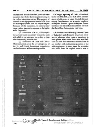
The document provides information on Radio Sets SCR-608-A and SCR-628-A, which are frequency-modulated radio telephone sets used for communication in anti-aircraft and anti-tank warning nets, as well as intra-battalion communication. The sets operate between 27-38.9 MHz with 100 kHz channel spacing, providing 10 preset channels with a range of 5-15 miles when powered by a 12 or 24-volt vehicle battery. The associated Radio Receiver BC-683-A has a sensitivity of 1 microvolt and uses an intermediate frequency of 2.65 MHz with a bandwidth of 80 kHz.

![WAR DEPARTMENT
WASHINGTON 25, D. C, 1 January, 1944.
TM 11-620, Radio Sets SCR-608-A and SCR-628-A, is published for the
information and guidance of all concerned.
[A. G. 300.7 (6 August, 1943).]
By order of the Secretary of War:
G. C. MARSHALL,
Chief of Staff.
Official:
J. A. ULIO,
Major General,
The Adjutant General.
Distribution:
CandH6(4);Bn 18(4); ICl8(2), 11(10).
(For explanation of symbols see FM 21-6.)
H
'
II
Generated on 2014-06-16 12:52 GMT / http://hdl.handle.net/2027/uc1.b3243867
Public Domain, Google-digitized / http://www.hathitrust.org/access_use#pd-google](https://image.slidesharecdn.com/230529091-tm-11-620-scr-608a-and-628a-141031054457-conversion-gate02/85/TM-11-620-3-320.jpg)


![TM 11-620
PAR. 3
I. DESCRIPTION
Quant itj
Table I. List of Components and Other Items Required
Article
Adapter Kit MC-471; includes:
1 Adapter plate; 15 in. x 35 in. x 1% in.
1 Reinforced plate; 16 in. x ll/2 in x TS3 in.
Necessary hardware
Antenna A-83-(*) (Phantom)
Battery Bracket BA-27 [for Remote Control Unit RM-29- (*) ]; 1 in Use, 1 Running Spare
Box BX-40 [for 30 crystal Holders FT-241-(*)]; includes 30 Holders FT-24l-(*)
Bracket (extension for Mounting FT-285)
Bracket (Cabinet CH-74-A)
Cabinet CH-74-A
Case CS-76-(*) [for Remote Control Unit RM-29-(*) ]
Chest CH-96 [for Microphone T-17, Headset HS-30-(*),
Box BX-40, spare tubes, technical manuals, etc.]
Clamp MC-423 (for Mast Section MS-51); 1 in Use, 1 Running Spare
Clamp MC-424 (for Mast Section MS-52); 1 in Use, 1 Running Spare
Cord CD-307-A [65-in. long, for Headset HS-30-(*)]; 1 in Use, 1 Running Spare
Connector and Bondnut; Appleton Electric Co. No. 61004 and BL-50 respectively
Connector and Bondnut; Appleton Electric Co. No. 61007 and BL-50 respectively
Cord CD-604 [for Headset HS-30-(*)]; 1 in Use, 1 Running Spare
Cord CD-689 (for Mast Base MP-48-A)
Cable WC-562
Cord CD-318-A (for Microphone T-45)
Cordage CO-212
Cordage CO-218 [for connecting slip ring to
Interphone Control Box BC-606-(*) in turret.]
Cover BG-96 (for radio set)
Cover BG-108 (for Mast Base MP-48-A)
Dynamotor DM-34-(*) [for Radio Receiver BC-683-(*)]; 12 volts;
includes the following Running Spare in BAG attached to dynamotor:
4-BRUSH (L.V.) INCLUDES SPRINGS
4-BRUSH (H.V.) INCLUDES SPRINGS
Dynamotor DM-35-(*) [for Radio Transmittet BC-684-(*)]; 12 volts;
includes the following Running Spare in BAG attached to dynamotor:
4-BRUSH (L.V.) INCLUDES SPRING
4-BRUSH (H.V.) INCLUDES SPRING
Frame FM-43 [for Cabinet CH-74-A or Mounting FT-237-(*) ]
Hardware Kit: Miscellaneous items
Headset HS-30-(*); 1 in Use, 1 Running Spare
(When Headset HS-30-(*) is not available, Headset HS-18 or HS-23 may be issued.)
Insulator IN-101
Insulator IN-104
Insulator IN-121 (1%-in. long, for insulating antenna wire through metal partition.)
Interphone Control Box BC-606-(*); includes attached hardware as follows: screws,
washers, clamps, clips, and hooks.
1
2
1
*
*
*
1
1
2
2
2
*
»
2
1
*
»
*
*
1
Generated on 2014-06-16 12:53 GMT / http://hdl.handle.net/2027/uc1.b3243867
Public Domain, Google-digitized / http://www.hathitrust.org/access_use#pd-google](https://image.slidesharecdn.com/230529091-tm-11-620-scr-608a-and-628a-141031054457-conversion-gate02/85/TM-11-620-12-320.jpg)


![TM 11-620
PAR. 37
IV. MAINTENANCE
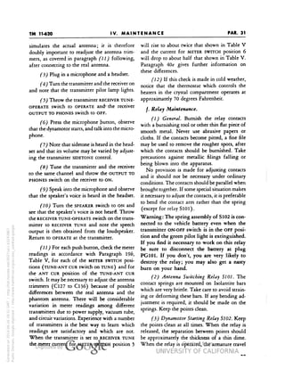
zero-beat. Set the TUNE-OPERATE switch to
OPERATE.
(11) Turn the switch of the adapter to
ALIGN and adjust the P (primary) adjusting
screw in FL4 for maximum indication on the
volt-ohmmeter.
(12) Restore the adapter switch to DISC and
trim the s screw setting for zero meter current.
Adjust the signal generator 50 kilocycles above
and 50 kilocycles below 2.65 megacycles and
make sure that the readings of the volt-ohm-meter
are approximately the same (but of op-posite
polarity).
(13) Vary the signal generator frequency
above 2.65 megacycles until the test meter de-flection
is greatest. Note the meter reading and
the generator frequency. The frequency should
be between 2.725 and 2.745 megacycles.
(14) Repeat step (13) below 2.65 mega-cycles.
The meter reading should be within 0.75
volt of the previous reading and the frequency
should be between 2.560 and 2.580 megacycles.
(15) Place the switch of the adapter at
CATH, with the signal generator set for 1.0-volt
output at 2.65 megacycles and note the reading
of the volt-ohmmeter for 4ater use in testing the
intermediate-frequency amplifier.
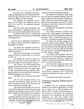
d. Alignment of I-f Amplifier.
(1) Reduce the signal generator output to
zero and connect its shielded cord to the control
grid of the modulator (terminal 4 of V2). Ex-posed
unshielded wires are dangerous and
should be kept as short as possible, preferably
less than 2 inches, including the clip.
(2) Adjust the generator to a small output
at 2.65 megacycles and adjust it for zero-beat
Generated on 2014-06-16 18:41 GMT / http://hdl.handle.net/2027/uc1.b3243867
Public Domain, Google-digitized / http://www.hathitrust.org/access_use#pd-google
with the intermediate-frequency oscillator when
the TUNE-OPERATE switch is set at TUNE. Then
restore the switch to OPERATE.
£3) With the switch of the adapter at CATH,
increase the generator output sufficiently to cause
a reading of 0.9 on the volt-ohmmeter. Adjust
the generator output from time to time during
the following alignment to maintain a meter
reading of between 0.6 and 0.9 volt.
MALLORY NO.3234J
SELECTOR SWITCH
-~f—
31 1O
2.5 OR 3.O-VOLT RANGE
OF VACUUM-TUBE
VOLTMETER t-1O7-(*X
OR R.C.A. 165, OR
HICKOK 312
OUTPUT VOLT-METER
[TEST
O SET I-56-C*)]
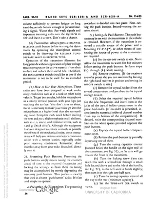
Fig. 56. Adapter FT-384-(*): Schematic
and Wiring Diagram
(4) Connect the 1000-ohm resistor between
terminals 3 and 4 of filter unit FL3A and adjust
the primary of FL3A designated P, for maximum
voltmeter reading.
Connect the resistor between terminals
1 and 2 of FL3A and tune the secondary of
FL3A, designated s, for maximum voltmeter in-dication.](https://image.slidesharecdn.com/230529091-tm-11-620-scr-608a-and-628a-141031054457-conversion-gate02/85/TM-11-620-110-320.jpg)


!["FOR TROUBLE LXX
CATION
'CAUTION: Q**i*ow VOLT
ttES ARE IXPOKD IT REOWEO FOR EOUIV.
HOGE METER REAOINOStM
OUTPUT METER
NEAOMC* «*
1 VOLT
t« VOLTS (APPROX.) 4OO CPS.
O.OS VOLT (APPHOXJ
16 VOLTS (APPROX.) 4OO CM.
/• pTJ MICROVOLTS (APPROW
'(<
It VOLTS (APPROX,) 4OO CPS.
^-iJ^ 'So MKROVOLTS (MAX.)
M) VOLT] (APPRO.) 4OD CPS.
/t"»oft |
1° f~* % 1 JO MICROVOLTS (APPHOX.)
16 VOLTf£|APPROX.)400 CPS.
lo'LAc?],'*'
r (_,
JO *>/ ] O MICROVOLTS (APPROX.)
W VOLTS (APPHOXJ 4OO CPS.
foijfoAfoi) IS-3 MICROVOLTS lAPPROX)
1 ,
It VOLTS (APPROX.) 4OO CPS.
(n^nii (^! f.T INPUT
II VOLTS (AfPNOX.) ISO CPS.
2O • • 4OO CPS.
1 .
2O • • IOOO
(72t (7^ (^ i —
II • • tSOO
"_
4 • • MOO
i ^ T .
"VoJcis!
t • • IOOO
j
!• • • coo
r— -— --------
i/Cf X-N Q 1 ^
^ ^
x-s 1 / ) ») 1
(0*1 O^^J3/I .
I x-E MADE THROUGH A .OOt Mf SERCS CONDENSER.
I vfW 4 OF Vt AND CHASSIS TO OBTAM THE EOUIVA-
4 AND B MICROAMPERES SHOULD BE DBTAINED.
i ( OM CLOCKWISE POSITION. A FREQUENCY MOOULA-
! VJUIRED FOR OUTPUT MEASUREMENTS MVOLVINt
IN OFF POSITION WHEN MEASUREMENTS ARE MADE.
SOURCE IS AVAILABLE.
'o'o
NOTES
I. ALL VOLTAtES SHOULD B
t. ALL SWITCHES EXCEPT'
1 VOLTAtES OVEN ARE AVERAtE REAOINtS.
NOT BE SERVICED JUST BECAI
MANUFACTURED EQUIPMENT Ci
ARE BASED ON
GIVEN SHOULD I
S. ACCURACY REQUIRES THAT ON M
READMt MUST BE M4HER THAN
•52394 O - 45 (Face p. 118) No. 1
VOLTAGES AT VACUUM TUBE SOCKET IU»«N»Li
FL4 (o±
IOOO OHM PER VOLT VOLTMETER MEASUREMENTS
(SEE NOTES S • T)
12 VOLT BATTERY
»»
Generated on 2014-06-16 19:44 GMT / http://hdl.handle.net/2027/uc1.b3243867
Public Domain, Google-digitized / http://www.hathitrust.org/access_use#pd-google](https://image.slidesharecdn.com/230529091-tm-11-620-scr-608a-and-628a-141031054457-conversion-gate02/85/TM-11-620-124-320.jpg)


![PAR. 44
TM 11-620
RADIO SETS SCR-608-A AND SCR-628-A
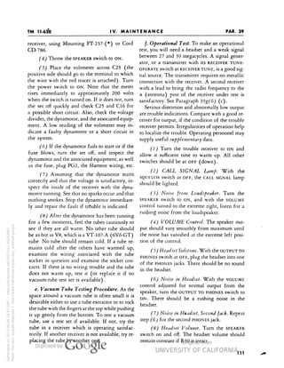
tween 300 and 800 volts. The lower voltage ap c. Tubular Ceramic Dielectric Capacitors.
plies to units with high-capacitance ratings; the Tubular treramic dielectric capacitors, which are
higher voltage applies to units with low<apaci- widely used for temperature compensation, are
tance ratings. Further details will be found in sometimes marked according to the RMA color
Standard C75/221 of the American Standards code shown in Fig. 67. As will be seen from the
Association. figure, the negative temperature coefficient is in-
SIGNIFIC
FIRST-ANT
FIGURES:
-. .-SECOND BODY
I
f
i
c=
—
=
DEC
MULT
MAL'
IFUER
LTOLERANCE
SIGNIFICANT FIGURES:
FIRST (BODY) SECOND
SIGNIFICANT FIGURES'.
FIRST (BODY) SECOND
SIGNIFICANT FIGURES'.
FIRST (BODY) SECOND
= m
1 m n
t ^
ryl
* ^ 11
1 "0% ' if
t
TOLERANCE DECK
MULTII
Generated on 2014-06-16 20:12 GMT / http://hdl.handle.net/2027/uc1.b3243867
Public Domain, Google-digitized / http://www.hathitrust.org/access_use#pd-google
*AL TOLERANCE-' It DE<
»LIER W IIUL1
:iMAL U TOLERANCE II
riPLIER
DECIMAL If
MULTIPLIER
First Second
Significant Significant
Color Figure Figure
B]
62
83
Decimal Multiplier
Tolerant
Black 0
0
1
—
Brown 1
1
10
± 1%
Red 2
2
100
± 2%
Orange 3
3
1,000
•± 3%
Yellow 4](https://image.slidesharecdn.com/230529091-tm-11-620-scr-608a-and-628a-141031054457-conversion-gate02/85/TM-11-620-156-320.jpg)


![I RECCJVCR (HF)
'BATTERY 14)
CRCXM) (-BATT-,
JiO2
CvCN HCATCRS
J 6OI DM -17- ( ] ?« VOLT DYNAUOTOR
OVEN
THERMOSTAT
199
Generated on 2014-06-19 20:20 GMT / http://hdl.handle.net/2027/uc1.b3243867
Public Domain, Google-digitized / http://www.hathitrust.org/access_use#pd-google](https://image.slidesharecdn.com/230529091-tm-11-620-scr-608a-and-628a-141031054457-conversion-gate02/85/TM-11-620-194-320.jpg)


