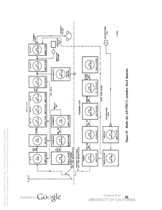
This document provides technical information on the operation and maintenance of Radio Set AN/TRC-7, including:
- Descriptions of the radio set components and their functions.
- Instructions for installation, operation, and preventative maintenance of the radio set.
- Troubleshooting procedures and repair instructions for issues with the equipment.


![WAR DEPARTMENT,
WASHINGTON 25, D. C., 22 FEBRUARY 1945.
TM 11-617, Radio Set AN/TRC-7, is published for the information
and guidance of all concerned.
G. C. MARSHALL,
Chief of Staff.
[A. G. 300.7 (18 Oct. 44).]
BY ORDER OF THE SECRETARY OF WAR:
OFFICIAL:
J. A. ULIO,
Major General,
The Adjutant General.
DISTRIBUTION:
AAF (2); AGF (2); ASF (2); T of Opn (2); Dept (2) DefComd
(2); Arm & Sv Bd (2); S Div ASF (1); Tech Sv (2); SvC (2);
PE (2); Gen Overseas SOS Dep (Sig Sec) (2); Dep 11 (2); Gen
& Sp SvSch (2); USMA (10); WDGS Lib (5); Lab 11 (2); A
(2); T/O-E 11-107 (3); 11-127 (a); 11-237 (3); 11-287 (3);
11-587 (3); 11-592 (3); 11-597 (3).
(For explanation of symbols see FM 21-6.)
Generated on 2014-06-12 14:35 GMT / http://hdl.handle.net/2027/uc1.b3243866
Public Domain, Google-digitized / http://www.hathitrust.org/access_use#pd-google](https://image.slidesharecdn.com/229388837-tm-11-617-1945-an-trc-7-141031053605-conversion-gate01/85/TM-11-617-3-320.jpg)


![0.375"-*-
-*)*.
•- 0.375"
J i L
_ e
0 250 - —
T--
- 0.250"
A
6
— i —
t
IDS
J
N
O
a
.
~.
I
i
II0
'«
T
OJ
i
.]
"T
a
o
I
I20
"^
2
0
+
~T"
f
"JO
b
o S t
t
I30
2 « =1
—
_ o» to
6
t
_TS_
1
"OJ
6
I
I40
J
"w
1
I45
.i
ri
6
t
I50
4
s
I
b
^
I56
!
Generated on 2014-06-12 15:18 GMT / http://hdl.handle.net/2027/uc1.b3243866
Public Domain, Google-digitized / http://www.hathitrust.org/access_use#pd-google](https://image.slidesharecdn.com/229388837-tm-11-617-1945-an-trc-7-141031053605-conversion-gate01/85/TM-11-617-125-320.jpg)

![WAR DEPARTMENT
UNSATISFACTORY EQUIPMENT REPORT
COMPLETE MAJOR ITEM
"BC-IOOO-A
C&>.
U. ». A. RBQ. NO.
£.43
NOMENCLATURE OF mnXJTIVE COMPONENT
SWfa.Kk>. £Z3S43-43CO Ciuf«W UHJT FT-Z43 4.30O
MANUFACTURER **J t
"P'Valeo
LENOTH OF SERVICE
14
44
^j
bO
DESCRIPTION OF TROUBLE AMD PROBABLE CAUSE
URE. MCCHANiCAU SUCTRiCAi. WORKMANSHIP. MATERtAL O
umt>>
SERVICE COMD1TIOHS
q
lNlfifi C
Kru. OF UBiNO PERSONNEJ. (oiccx OMK]
Itfrm C-gMolcAt. cKcck, bt.wiflu.ic.qvt c*M<4tti OchfoKi «."-Hmc oP ^c^uftLcKutx.
t*T DCD. "*^ *^ OUOtMATXXO omcnt
INSTRUCTIONS
I It i. imperative that the Chlel el Technical Service
at (be eaiLi«t practical mament af anv aatutnicttaaal, dee*jn, ar apera'
deltx^ ia mattrlel. ThU farm li deeJaned to iacilttote ych repart, and to pi
"D uethad al •ubmimno the required di'
praitd«
2. Thli lam will be tued far repartng mauuiacturing, de*ifn ar aperatlaBaI
deUatoln mat trie] with a view to lmpraiina and canectlng inchdetecn, and lar
Me tn TMXnmeadlna madlbcananc af mattrnl
3. Thii hum will nat be ueed lar reparting ta^*IM, t»lQted material defecte at
«ar lar the replacement, repair, ar the leiae al parti and equipment. tt daM nat
lepluce cunently aathartted aperaHanal 01 pntarmance recordi.
4. Reparti al oalhinctiOai and aaakUnH iBvahrlaa nmmnnman will oanttniie
ta be nibmltted 01 directed tn the manner deearlbed ln AB 78O-10 (Cnua«
Generated on 2014-06-12 15:18 GMT / http://hdl.handle.net/2027/uc1.b3243866
Public Domain, Google-digitized / http://www.hathitrust.org/access_use#pd-google
'W. D., A. 0^0. Form Bio. Mt
S. It wtll nat t» piacttcablo ar dMlrable tn
at U>e r^art. Ha*«er. th. repart -iauld be
to «r*di!. MOe«anr aarreaHve actian. / ''
pttntdad fai tn the blank ipacM ikauld tw „ __ _
Fkatoaraphi, ^etch« a. ol« illuttativ. mat. rial
8. Whuii COMe artee wh.tre n to
e tn arder ta QMUIe >afety
to fill aQ blank •
- -^J<
ai at a**.
pOrtiM.-
BUalcanan .,r. auth.inied. TUe lam ihauli be ueed ti
7. Thli torn will be made aut by udna ar wrvlae argaatoattaaei and fcniiiii.»*
in duplicate thrauah cammand channeli to lhe chlel al technical eerriae. Tke
HOa capy ta the Cnmmandina Geneial, Army GraundFaraee ar Army Air Faraw
whichever t* applicable, aad ta the Ccmmaadlng General, Army Serrtre Fun™.
6. Heceedty (at mlag Ihle farm will be determined by the uitng ar eeniae Ui ^
TLI3596
Figure 73. Unsatisfactory Equipment Report.
112](https://image.slidesharecdn.com/229388837-tm-11-617-1945-an-trc-7-141031053605-conversion-gate01/85/TM-11-617-127-320.jpg)


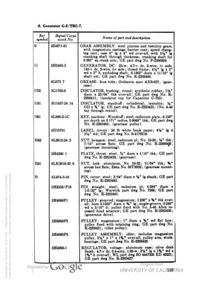
![a. Maintenance Parts for Radio Set AN/TRC-7.
Ref
symbol
Signal Corps
stock No.
Name of part and description
:W-48
2A203A-281
3H160-47
2Z553-48
3B295-49
3A30
3A58
3A70
1F430-127
3E6000-220
3E6000-240
2Z1891-175
3E1307A
3E1318
3E1604
ANTENNA, phantom: Army-Navy Jftantom Antenna
TS-281/TRC-7; Sig C spec No. 271-3103; (Plug PL-
259 one end with miniature screw-type socket across
term; socket holds 6-v, 150-ma pilot lamp).
BAG CW-47/TRC-7: canvas, olive drab finish; 14%"
lg x 8%" thk x 16" h; felt padding 1" thk; Sig C
spec No. 271-3103; (for receiver-transmitter and ac-cessories).
BAG CW-48/TRC-7: canvas; olive drab finish; 37" lg
x 14" wd x 10" thk; Sig C spec No. 271-3103; (for
antenna roll and contents).
BAG CW-49/TRC-7: canvas; olive drab finish; 12%"
wd x 6%" thk x 14" h; Sig C spec No. 271-3103; (for
receiver-transmitter and accessories).
BATTERY BA-30: dry; portable; metal can; 1.5-v;
2-13/32" h x 1-11/32" diam; (for Remote Control
Units RM-52 and RM-53).
BATTERY BA-58: dry; 1%-v; C battery bias; Pen-light
Generated on 2014-06-12 15:25 GMT / http://hdl.handle.net/2027/uc1.b3243866
Public Domain, Google-digitized / http://www.hathitrust.org/access_use#pd-google
cell type No. T1AA.
BATTERY BA-70: dry; A unit 4.5-v, B unit No. 160 v,
B unit No. 2 90 v; rectangular; 7%" h x 10" wd x
4%" d.
CABLE ASSEMBLY, RF: Sig C Cord CG-127/U;
rubber jacketed; 48" lg; RF Cable RG-5/U; Sig C
dwg No. SC-D-14126; (width Plug PL-259 one end,
socket No. 46-P6 other end).
CABLE ASSEMBLY, power: Sig C Cord CX-220/
TRC-7; rubber jacketed; 15 ft lg; 3-cond; shielded;
Sin C dwg No. SC-D-16852; (with AN-3106-14S-7S
connector on one end; AN-3106-16S-5P connector on
other end); (connects generator to receiver trans-mitter).
CABLE ASSEMBLY, power: Sig C Cord CX-240/U;
rubber jacketed; 48" lg; Sig C dwg No. SC-D-14127;
(4-prong male connector one end, female plug on
other end); (for test).
CASE CY-275/TRC-7: aluminum; empty; for spare
tubes; 12%" lg x 4%" wd x 2%" h; Sig C dwg No.
8C-D-16849.
CORD CD-307-A: headset; RC; %" diam x 65" ]g;
two No. 20 stranded copper cond; Sig C dwg No.
SC-D-2019; spec No. 71-1105; (with Plug PL-55 one
end; J.ick JK-26 other end).
CORD CD-318: micronhone; RC; Sig C spec No. 71-
971; (7 ft Cordage CO-145 with Plug PL-68 on one
end: 8 ft Cordage CO-119-B with Jack JK-55 on one
end); (for Microphone T-45).
CORD CD-604: headset; RC; round: 0570" diam; 6
ft lg; 2-cond; Sig C spec No. 71-1525: (with trans-former](https://image.slidesharecdn.com/229388837-tm-11-617-1945-an-trc-7-141031053605-conversion-gate01/85/TM-11-617-134-320.jpg)


![tl. Generator G-3/TRC-7.
Rej
symbol
Signal Corps
stock No.
Name o] part and description
3H5041 2-2
RING, retainer: steel; for fixing pulley to shaft-
0.173" ID; sect 0.025" sq; GE part dwg No. K-
2263482.
H303
6L6832-8 3AL
SCREW, machine: fil H; aluminum; anodized; No.
8-32 x W lg; (gearcase).
H304
6L6832-16 3AL
SCREW, machine: fil H; aluminum; anodized; No.
8-32 x 1" lg; (gearcase).
H305
6L6256-3-1AL
SCREW, machine: flat H; aluminum; anodized; No.
2-56 x 7/32" lg; (gearcase).
H306
6L6832-8AL
SCREW, machine: flat H; aluminum; anodized; No.
8-32 x %" lg; (gearcase).
H2
6L6832-8 81CS
SCREW, machine: hex hd; steel, cadmium pI; No.
8-32; %" lg w/ 13/64" lg thd; head %" across flats,
%" thk; GE part dwg No. K-2263445; (hinge bolt
for generating unit).
H601
6L6632-3-1 49S
SCREW, machine: RH; steel, zinc pI; No. 6-32 x
7/32" lg; GE part dwg No. K-2268418; (special head
0.231" diam x 0.071" thk, slotted); (capacitor mount-ing).
H3
Generated on 2014-06-12 15:35 GMT / http://hdl.handle.net/2027/uc1.b3243866
Public Domain, Google-digitized / http://www.hathitrust.org/access_use#pd-google
6L18505-5 41
SCREW, set: headless; hex socket type, self locking;
steel; cadmium pI; No. 5-40; 5/16" lg over-all; GE
part dwg No. K-2268422; (for grooved pulley).
X701
2ZK8666-15
SOCKET, tube: o'ctal; molded bakelite or steatite;
bodv, 1%" diam x %" h; Vicinite No. 115015-2,
Amphenol No. SS8M on S-STM; GE part dwg No.
K-2263421; (voltage regulator mounting).
3H2358/S15
SPRING: helical; 0.025" OD music wire; 8 turns close
wound with %" projection of wire at ends of spring;
0.206" ID x 0525" lg; Warwick part dwg No. US-
70135; GE part dwg No. K-2263480.
3H5280 3
SPRING: helical; phosphor bronze; %" OD x W lg
with 05-lb pull and 1%" lg with 0.7-lb pull; GE part
dwg No. K-2263498; (tension for idler pulley assem-bly).
6L58022-12C
WASHER, flat: steel, cadmium pI; 0.159" ID x 9/32"
OD x 0.031" thk; GE part dwg No. K-2263499; (idler
pulley).
6L58023C
WASHER, flat: steel, cadmium pI; 0.187" ID x 11/32"
OD x 0.031" thk; GE part dwg No. K-2263484-1;
(idler pulley).
H307
3G 1838-8 19
WASHER, flat: textolite: %" OD x 0.257" ID x 0.062"](https://image.slidesharecdn.com/229388837-tm-11-617-1945-an-trc-7-141031053605-conversion-gate01/85/TM-11-617-147-320.jpg)


![Page 110. Fig. 72. Change the dimension in the lower left-hand corn
from 2.000" to 1.750"; change the over-all dimension from 11.65(
to 11.406".
Page 114. Par. 115. Delete paragraph 115 and substitute the follo-v
ing therefor:
115. NEUTRALIZATION OF TRANSMITTER POWER
AMPLIFIER.
a. General. Neutralizing capacitors C84 and C85 are adjusted at t
factory and should need no attention in the field. However, if tube V]
is replaced it may upset the neutralization. When the neutralization
out of adjustment the power-amplifier stage will go into oscillation. Tl
condition can be recognized if the brightness of phantom Anteni
TS-281/TRC-7 does not change as capacitor C61 (or C62) is adjuste
If it is certain that the neutralization is out of adjustment, the followii
procedure may be followed.
b. Neutralization Procedure.
(1) Align the transmitter using a crystal corresponding to a fn
quency lower than 130 me. Follow the method outlined in paragraph 11
up to and including the adjustment of capacitor C79 (or C80) describe
in subparagraph b(3) (c). Remove the plate supply voltage of tube Vl
by opening the connection between terminal 4 of transformer T8 ar
capacitor C88. This is most easily done by unsoldering the green les
from the main wiring cable at terminal clip 5 on switch wafer B. S
capacitor C81 (or C82) at 100 me. Set the meter switch to position
The meter now reads grid current of the final amplifier.
(2) Set neutralizing capacitors C84 and C85 at half maximui
capacitance.
(3) Retime the grid circuit of tube V15 by adjusting capacitor C7
(or C80) for maximum meter deflection.
(4) Tune slowly through resonance of tube V15 plate circuit b
adjusting capacitor C81 (or C82). The meter deflection dips when passin
through plate circuit resonance. Observe the amount of dip produce*
Reset capacitor C81 (or C82) to 100 me.
(5) Increase the capacitance of capacitors C84 and C85, each bv
small amount, by using the insulated blade of Alignment Tool TL-314/t
(6) Repeat steps (3) and (4) above. If the meter dip has decrease(
continue to increase the capacitance of capacitors C84 and C85 in smal
equal amounts, each time repeating steps1 (3) and (4). If the meter di
6
Generated on 2014-06-12 15:39 GMT / http://hdl.handle.net/2027/uc1.b3243866
Public Domain, Google-digitized / http://www.hathitrust.org/access_use#pd-google](https://image.slidesharecdn.com/229388837-tm-11-617-1945-an-trc-7-141031053605-conversion-gate01/85/TM-11-617-173-320.jpg)


![No. 1-125
Figure 45. Tube puller No. 1-1S5 and tube -puller No. 11-16.
/
VI ^
ft /x
SI/
/
jT-
11 *
... / IDOMMf
. I "^ If .
-fc A
2*2:5 ~ *
<C2
N
^^ I r^—
I.200
MMF
A
'» TO GRID
OF MIXER
(V2)
MMF''
CUM
MF
yce
-5
i
27' 3 t ^
^27
C54
J MMF^fc
C5
I.200
C3
MMF'
MMF g]L2
CJL3
I0;
-I,200 S)L|4
MMF S
C8 -— »~.
I.200
MMF-J-MMT
|
I -i-
-^
LI3 RBI
|
I
6BOOA
1"
TO ANTENNA
SWITCHING
RELAY Kl
>
TO AVC LINE
»-TO PINB T0 PLATE
(V2j OF HARMONIC AMPLIFIER
NOTE:
=T= IS SYMBOL FOR FIXED CAPACITOR
# IS SYMBOL FOR VARIABLE CAPACITOR
Figure 60. Receiver r-j amplifier.
11
Generated on 2014-06-12 15:39 GMT / http://hdl.handle.net/2027/uc1.b3243866
Public Domain, Google-digitized / http://www.hathitrust.org/access_use#pd-google](https://image.slidesharecdn.com/229388837-tm-11-617-1945-an-trc-7-141031053605-conversion-gate01/85/TM-11-617-178-320.jpg)


![[English Version]Maker-Ray Product Brochure V3 .pdf](https://cdn.slidesharecdn.com/ss_thumbnails/englishversionmaker-rayproductbrochurev3-260113094444-0156dbdc-thumbnail.jpg?width=640&height=640&fit=bounds)


![Alan Lucas - [Template] [Template] [Template] ScienceFairProjectTemplate.pptx](https://cdn.slidesharecdn.com/ss_thumbnails/alanlucas-templatetemplatetemplatesciencefairprojecttemplate-260106222421-b6ad9ab7-thumbnail.jpg?width=640&height=640&fit=bounds)


