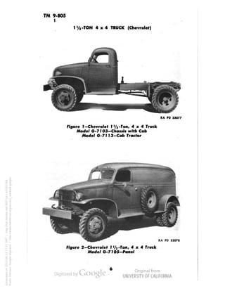
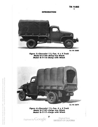
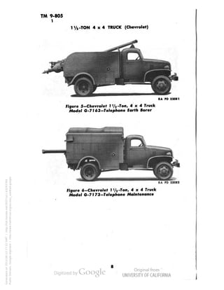
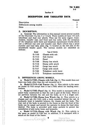
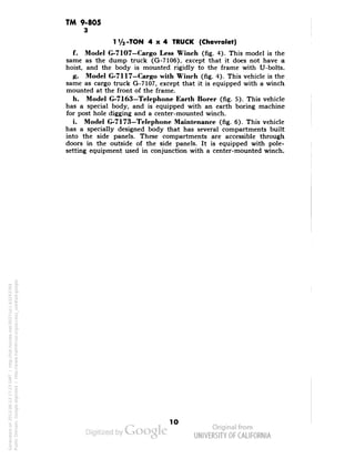
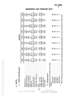
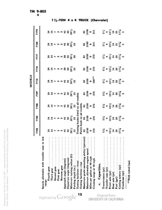
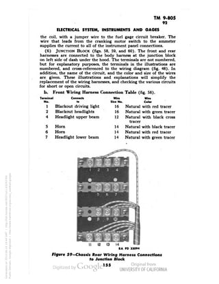
This document provides descriptions and technical data for several models of the 1 1/2-ton 4x4 Chevrolet truck used by the military between 1943-1945. It details the various configurations including chassis, cab, panel, dump, cargo, telephone, and specifications. The models share many core components but have specialized bodies and equipment tailored to their intended functions.
![WAR DEPARTMENT
Washington 25, D. C., 30 December 1943
TM 9-805—IVi-ton 4x4 Truck (Chevrolet), is published for the
information and guidance of all concerned.
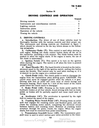
[A. G. 300.7 (22Nov 43)]
BY ORDER OF THE SECRETARY OF WAR:
G. C. MARSHALL,
Chief of Staff.
OFFICIAL:
J. A. ULIO,
Major General,
The Adjutant General.
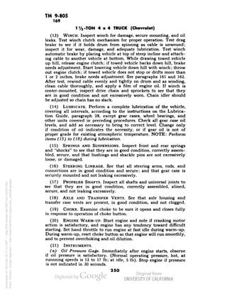
DISTRIBUTION: X.
(For explanation of symbols, see FM 21-6.)
Generated on 2013-06-13 17:16 GMT / http://hdl.handle.net/2027/uc1.b3243764
Public Domain, Google-digitized / http://www.hathitrust.org/access_use#pd-google](https://image.slidesharecdn.com/tm9-805-141108052035-conversion-gate02/85/TM-9-805-3-320.jpg)
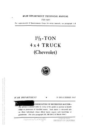
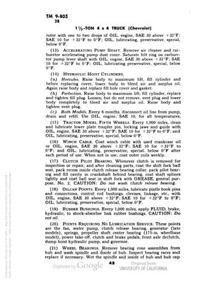
![TM 9-805
28
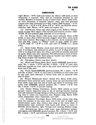
LUBRICATION
1X1
in
M li
III 1
i^f
1!
$ S-2 »-£ S
z _. = -- « o
Will i
:2-!ill*3 i
*=i:;i!° .
!5i^iJ*i
0 *~ o -• i - '*
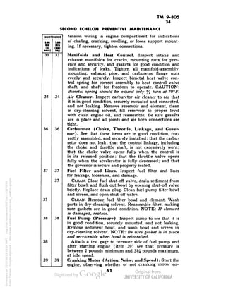
la ill til Ji
ill
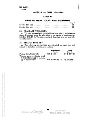
I III ,d'O^
||Jl S£J|J
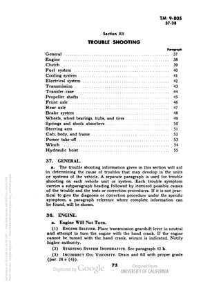
-ii Mils
I]
^"
1
1
"> *
Hi"' 111?4'
11
J^^-S n. > " » 2?
§•:'
l|JiJ Ji^l.
**Zsg KjK
« •
SJEe,B S-"'"
1
I
> Instruction
• and S»rvic« b»lo
iiu! m
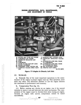
if
II
i'S S • I **1 °
j= 8-fs i? is~:
h
!*• ^•"° ; <^rs ES-
•J] o
Jt
.{:t«:ii!^'
s» •
-3
vMHIslil!i
!+-;_
2 Van1
!1±1
1
•FLUID. br*lt. hyc
-FLUID. ihock-*b«
ft,
A
1!
pj
j
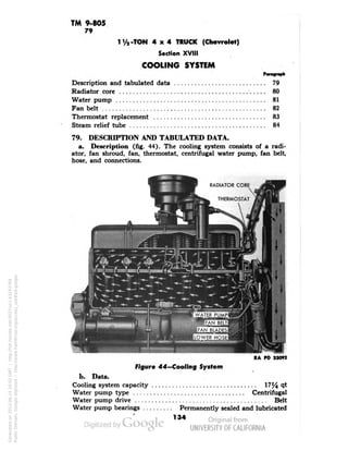
1
J
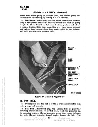
II
a.22 _•
jjSiC
S o a
I9ZZ
;=•
Generated on 2013-06-13 17:47 GMT / http://hdl.handle.net/2027/uc1.b3243764
Public Domain, Google-digitized / http://www.hathitrust.org/access_use#pd-google](https://image.slidesharecdn.com/tm9-805-141108052035-conversion-gate02/85/TM-9-805-46-320.jpg)
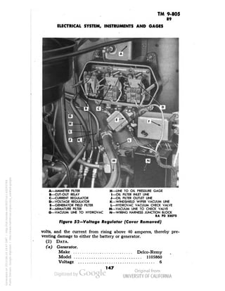
![TM 9-805
30
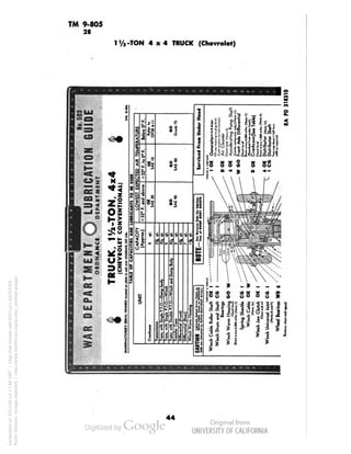
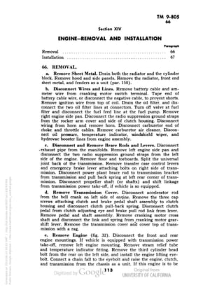
1V2-TON 4x4 TRUCK (Chevrolet)
Section VIII
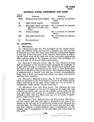
TOOLS AND EQUIPMENT STOWAGE ON VEHICLE
Vehicle tools 30
Vehicle equipment 31
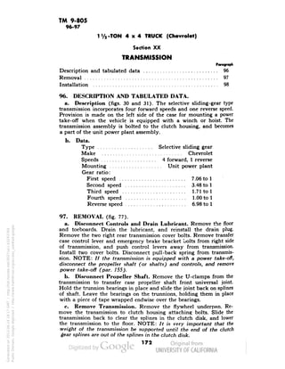
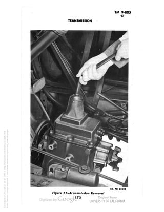
Vehicle spare parts 32
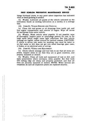
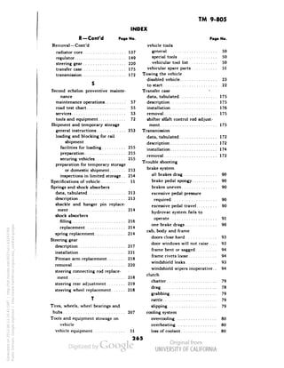
30. VEHICLE TOOLS.
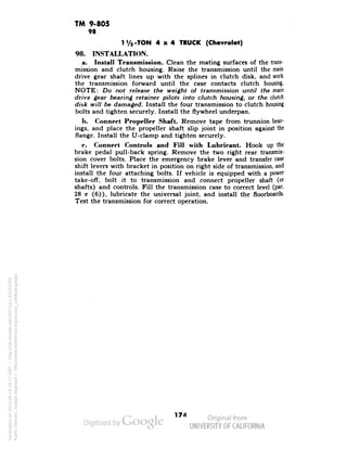
a. General. Each vehicle is equipped with the tools listed in sub-paragraph
c below so that minor repairs can be performed by the
driving personnel. The larger tools, and a tool bag containing small
tools, are located on the several models as follows:
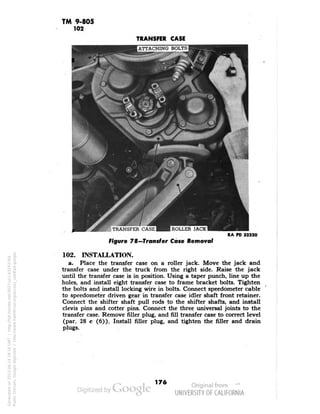
Model . Too) Location
G-7103—Chassis with cab Under driver's seat
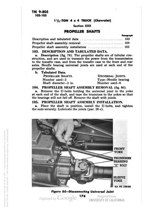
G-7105—Panel In back of driver's seat back
G-7113—Cab tractor Tool box on right running board
G-7106—Dump less winch I TT
G-7116-Dump with winch f Under dnver s seat
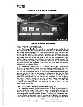
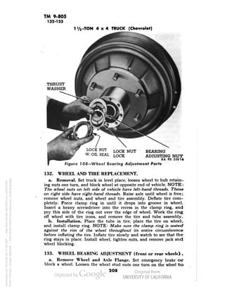
G-7107—Cargo less winch I In compartment under body tail
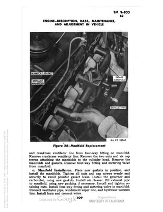
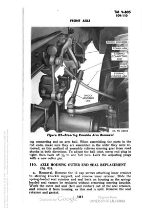
G-7117—Cargo with winch f gate
G-7163—Telephone earth borer I TT ,
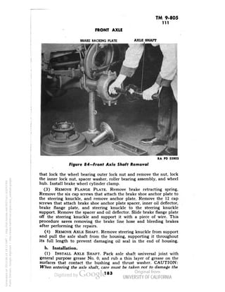
G-7173-Telephone maintenance f Under dnvers seat
b. Special Tools. A list of special tools for second echelon use
will be found in section XI.
c. Vehicular Tool List. , . ,, . ,,
„ . . .. Federal Stock No.
Crank, engine starting
Hammer, machinist's, ball peen, 16-oz 41-H-523
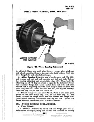
Handle, wheel bearing nut
Handle, wheel wrench
Pliers, combination slip joint, 6-in 41-P-1650
Screwdriver, clutch head, %2-in 41-S-1117-4
Screwdriver, clutch head, %-in 41-S-1117-6
Screwdriver, clutch head, y16-in 41-S-1117-8
Screwdriver, common, 6-in. blade 41-S-1104
Wrench, adjustable, automobile type, 11-in 41-W-448
Wrench, adjustable, crescent type, 8-in 41-W-486
Wrench, engineer's, open-end, %- x 7/16-in 41-W-991
Wrench, engineer's, open-end, l/2- x !%2-in 41-W-1003
Wrench, engineer's, open-end, %6- x ] Vie-in 41-W-1005-5
Wrench, engineers, open-end, %- x 2%2-in 41-W-1008-10
Wrench, engineer's, open-end, %- x %-in 41-W-1012-5
Wrench, spark plug
Wrench, special hex socket (winch trucks only)
Wrench, wheel
Wrench, wheel bearing nut
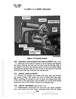
Wrench, clutch feed shaft coupling (earth borer only)
Wrench, clutch shaft bearing nut lock (earth borer only)
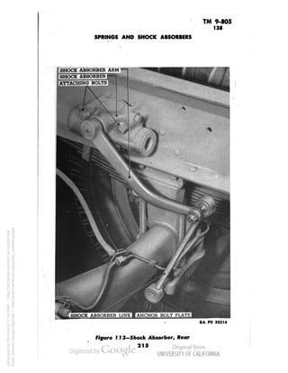
50
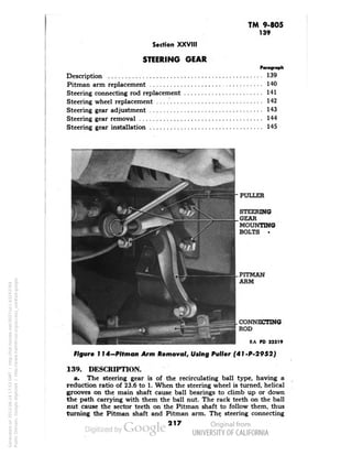
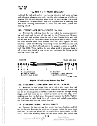
Generated on 2013-06-13 17:48 GMT / http://hdl.handle.net/2027/uc1.b3243764
Public Domain, Google-digitized / http://www.hathitrust.org/access_use#pd-google](https://image.slidesharecdn.com/tm9-805-141108052035-conversion-gate02/85/TM-9-805-49-320.jpg)
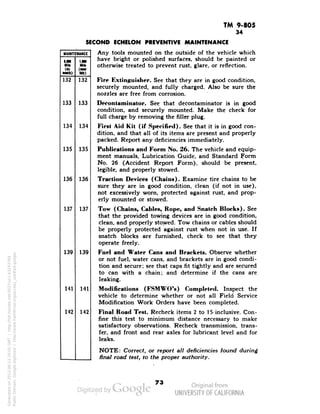

![TM 9-805
87
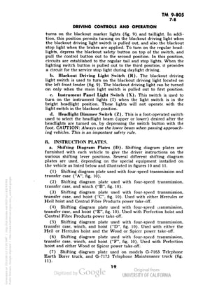
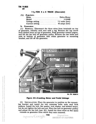
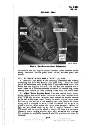
1 '/, -TO
N 4 x 4 TRUCK (Chevrolet)
*.!?* DOTTED LINES S
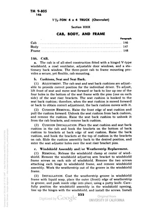
1 . ADDITIONAL CK
i USED ON
„ IX G-7113 MODELS
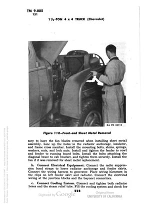
HOW CHASSIS
CUITS REAR HARNESS CHAS
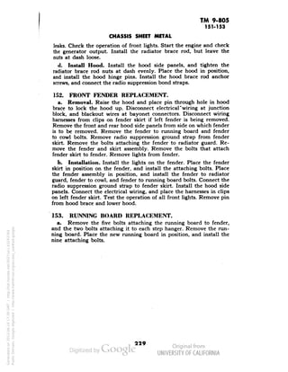
G-7H3 MODELS REA
ONLY ONLY HARN
SIS
1
s-s. rii .
ss
S.T. V— 10-,
..O.T.L/a-1]
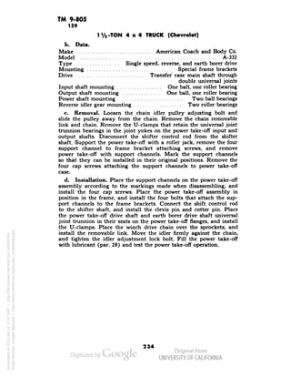
TRAILER
CONNECTOR , | |
B.K. S.
.^J~^f.^—i
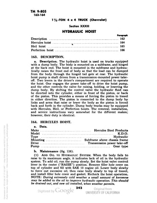
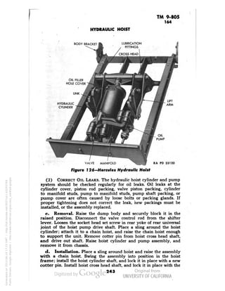
10 fe^ £
t1"1
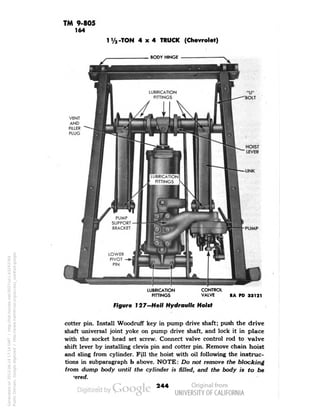
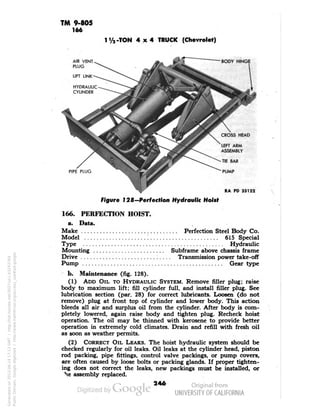
— M- 1 ne^ — /-I
^-194"
'Jit 9 — 1
| S G T| j
2 ~
'Xl? W"
PE
r— ^« _J
'S i
.s — ^
E!c
~T
3__ | —;
1 |3 DIMM
/TN SWITC
Generated on 2013-06-14 19:59 GMT / http://hdl.handle.net/2027/uc1.b3243764
Public Domain, Google-digitized / http://www.hathitrust.org/access_use#pd-google
:s^^
ML
-^4 —
L 1 BL*C
-*/Pf STOP'LAMP DRIVS'^
K-OUT x-x
-ia
3 LIGHT-— ( 3:
ITCH ^— ^
FUEL GAGE
TANK UNIT
V — / SWITCH
—6 '-•^>-
12
LOAD REGULATOR
DOME LIGHT
SWITCH
- ye:
I
J HORN BUTTON — »-(JD— 3—
— . TRAILER
BRAKE
CONTROLLER
DOME LIGHT-B.
O.T.[V 1 ,
•*p— S
• ^,8"l
"•asUr-^ o „ 8
FUEL GAGE "J (,
Jt
U-10-](https://image.slidesharecdn.com/tm9-805-141108052035-conversion-gate02/85/TM-9-805-141-320.jpg)
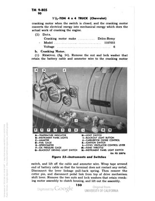
![TM 9-805
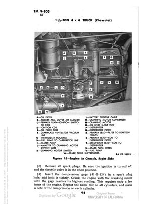
93
11/2-TON 4x4 TRUCK (Chevrolet)
CENTER LINE AHEAD-Lr
I nftlNU t«Mr v
~
^CENTER LINE
]/ OF TRUCK
SPOT SHOULD BE^
rEREDUPAND
N ON LINE A-A
r
^-CENTER LIN
/ OF RIGHT HX
^-HOT SPOT SHOULD
/ BE CENTERED SIDEWAYS
ON LINE B-B
I/
,^-HEADLAMP
/I
f////////,/fr,
- ^,"//i
>
~ •
S//////////<
s//, /'/'///,//
V
V| ,
3 FOR ALL
AIM RIGHT Ht
SAME AS LEF
CENTER HOT
LHOTSPO'
- OF HEADLAMP
SIDEWAYS O
UPPER E
EAM
NO FURTHER ADJU
STMENT IS
Generated on 2013-06-14 19:42 GMT / http://hdl.handle.net/2027/uc1.b3243764
Public Domain, Google-digitized / http://www.hathitrust.org/access_use#pd-google
NEEDED FOR LOW,ER BEAM
B
c
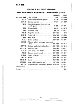
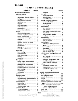
RA PD 32279
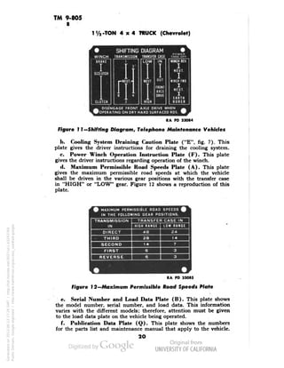
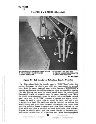
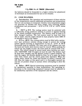
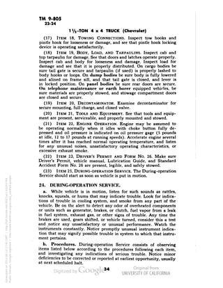
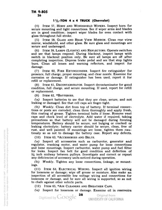
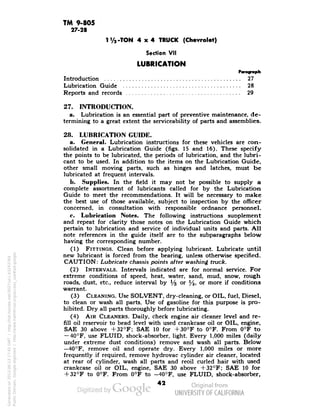
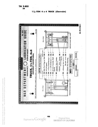
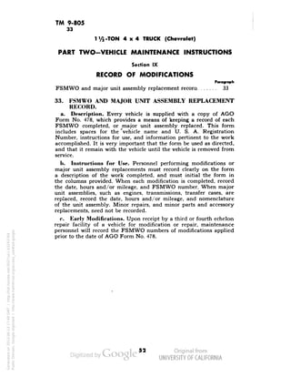
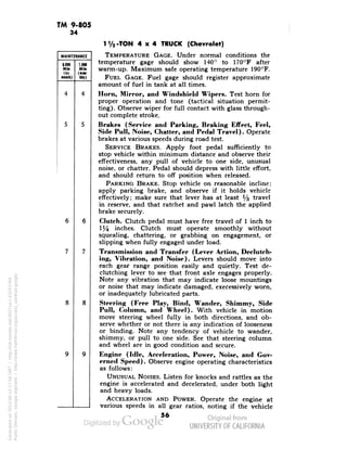
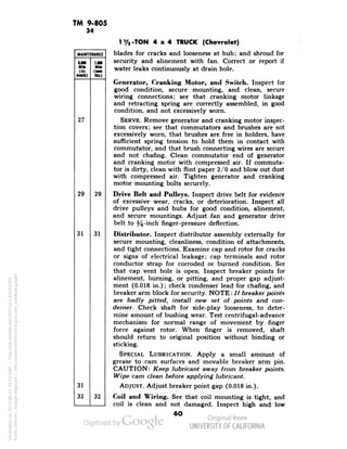
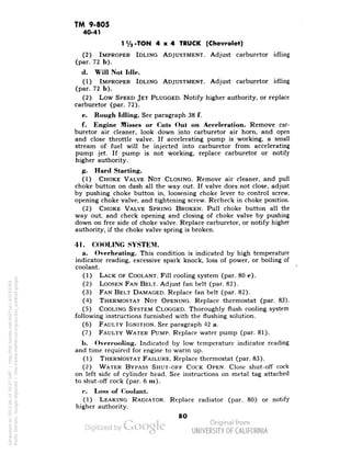
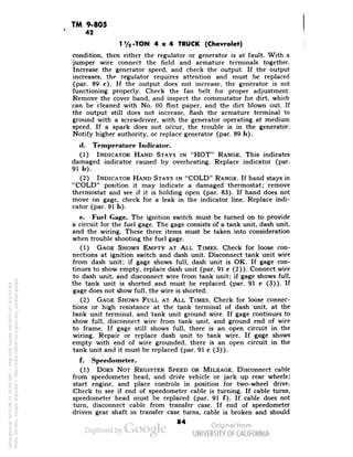
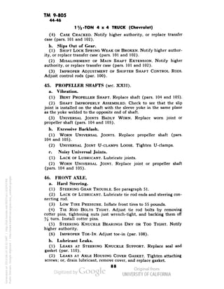
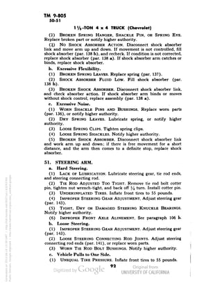
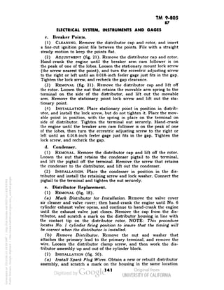
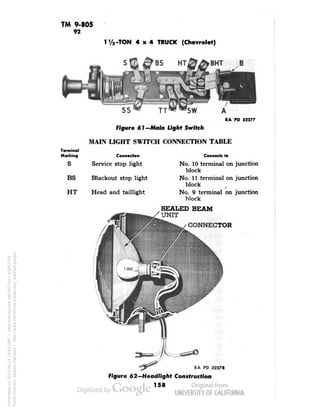
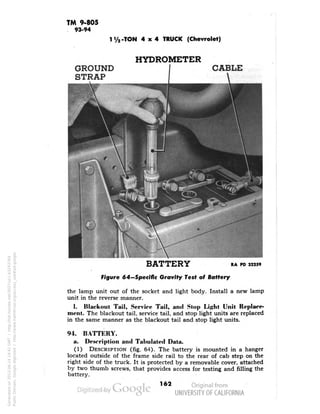
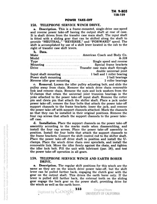
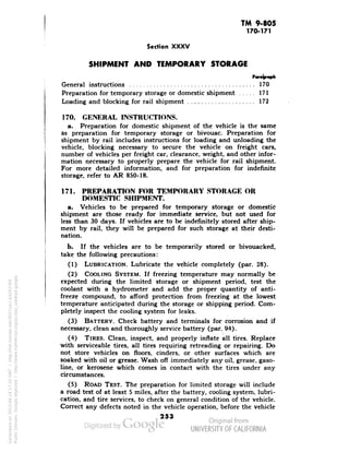
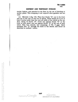
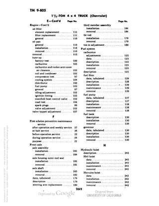
Figure 63—Headlight Aiming Diagram
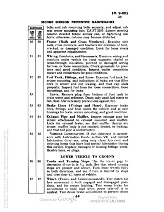
b. Headlight Aiming.
(1) INTRODUCTION (fig. 63). Headlights may be aimed by the use
of a portable aiming screen which can be constructed very easily.
Construct a frame approximately 5 feet high and 8 feet long. The
frame can be constructed of common lumber approximately 1 inch
x 3 inches. Cover the frame with a piece of light-colored cloth; make
a narrow, dark, vertical stripe down the center, and two stripes, 18
inches from each side of the center stripe and parallel to it, as shown
by lines "B" and "C" in the illustration. Then place nails on the end
upright of the frame so that the nails are 1 inch apart, beginning at
about 2 feet from the bottom of the screen and continuing upward
about 2 feet. Then secure a piece of black tape about yz- or 3^-inch
wide and about 6 inches longer than screen is wide. Fasten a weight
on each end of the tape to keep the tape stretched when laid across
the nails as shown by line "A" in the illustration.
(2) AIMING HEADLIGHTS. Place the screen against a wall in a
fairly dark corner of room that is fairly level. Run the vehicle directly
in front of the screen so that the headlights are 25 feet from the
screen. Measure from the floor to the center of the headlights, and
place the black tape across the screen so that it is 3 inches below
the center of the headlights. Turn on the upper beam of the head-lights,
and cover one of the lights. Check the location of the beam
on the screen. The center of the hot spot should be centered on the
intersection of the vertical and horizontal lines as shown in figure 63.
If the aim is incorrect, loosen the nut on the headlight mounting
bolt, and move the headlight body on its ball and socket joint until](https://image.slidesharecdn.com/tm9-805-141108052035-conversion-gate02/85/TM-9-805-159-320.jpg)
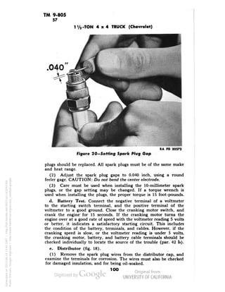
![TM 9-805
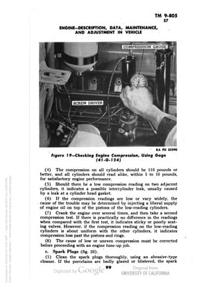
110-111
1 Va -TON 4x4 TRUCK (Chevrolet)
TA|NERGASKET
OUTER Eh
OUTER END SEAL (FELT AND RUBBER))
OUTER END SEAL (SPRIN< LOADED)]
'SPRING LOADED SEAL RETAINER}
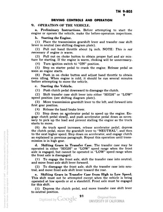
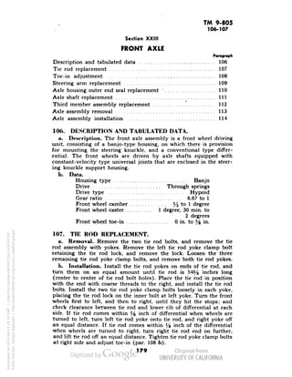
OUTER END SEAL INNER RETAINER ^^^^ RA PD 33046
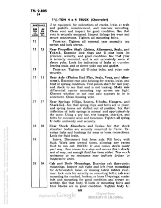
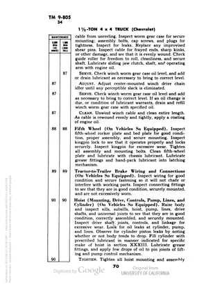
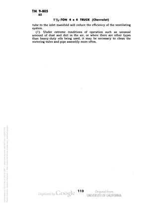
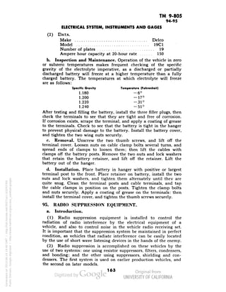
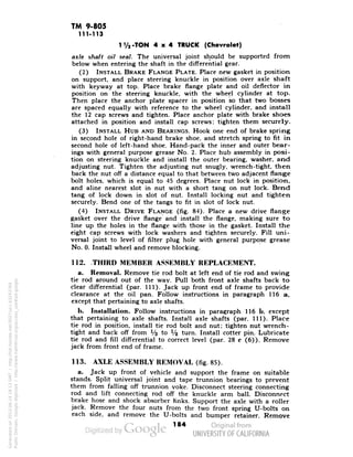
Figure 83—Outer Seal Replacement
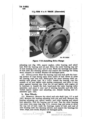
b. Installation. Place a new seal retainer gasket on knuckle sup-port
with the diagonal cut as close to top as possible, and make sure
bolt holes line up. Install the seal retainer. Place the new outer end
seal (felt and rubber) in the retainer so that the taper of seal fits
the curvature of the axle outer end ball, and the diagonal cut will
be at the top. Place the spring-loaded seal and seal retainer against
the felt and rubber seal, and install the lower half of the inner
retainer, holding it in place with two or three cap screws installed
loosely. Position the spring-loaded seal uniformly around the
spherical bolt with a small screwdriver, and install the upper half
of the inner retainer. Install and tighten all of the retainer cap
screws.
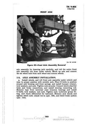
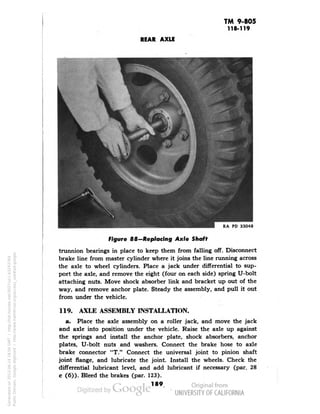
111. AXLE SHAFT REPLACEMENT (EITHER SHAFT).
a. Removal (fig. 84).
(1) REMOVE WHEELS. Loosen the six wheel stud nuts on front
wheel two turns. Raise front of vehicle until the wheel clears the
ground, and support axle housing on jack stand or suitable blocks.
Remove the six wheel stud nuts that were previously loosened, and
remove the wheel.
(2) REMOVE HUB. Remove the eight bolts and lock washers
attaching drive flange to hub. Install two bolts in the tapped holes
of flange; screw them in alternately to remove flange. Raise the tangs
182
Generated on 2013-06-14 18:13 GMT / http://hdl.handle.net/2027/uc1.b3243764
Public Domain, Google-digitized / http://www.hathitrust.org/access_use#pd-google](https://image.slidesharecdn.com/tm9-805-141108052035-conversion-gate02/85/TM-9-805-181-320.jpg)


![DESIGN AND FABRICATION OF THE IBM 90-90 SEAT BELT CLAMP KIA VEHICLE[1].pptx 2...](https://cdn.slidesharecdn.com/ss_thumbnails/designandfabricationoftheibm90-90seatbeltclampkiavehicle1-260116160442-70ff67fc-thumbnail.jpg?width=640&height=640&fit=bounds)


