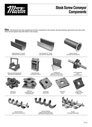
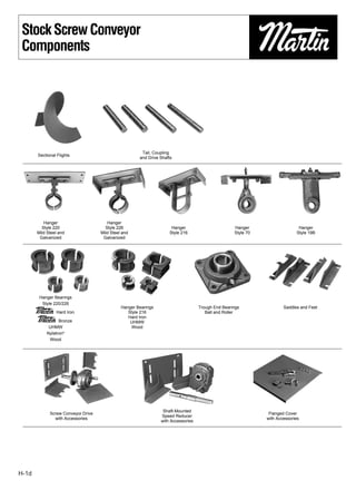
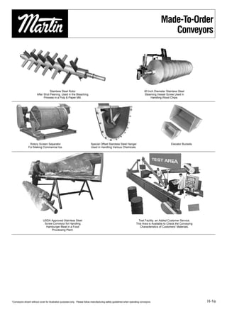
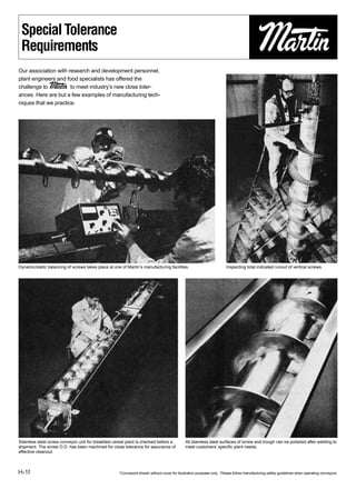
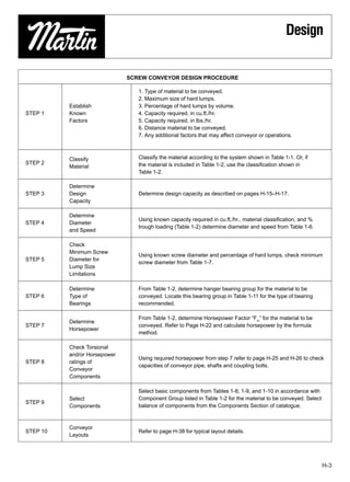
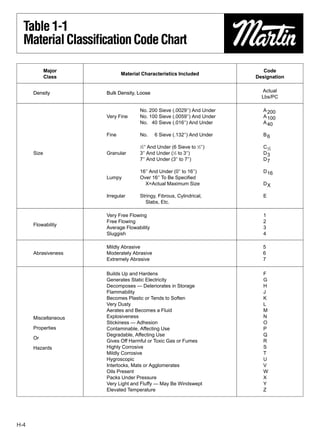
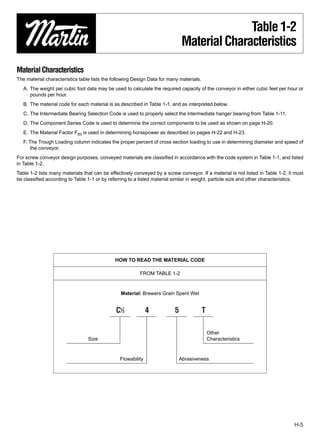
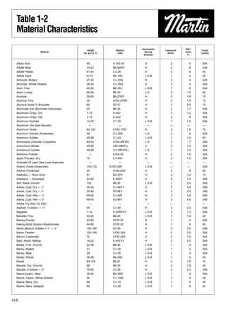
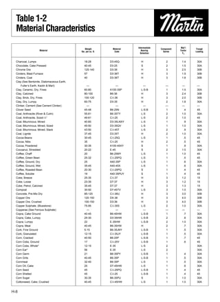
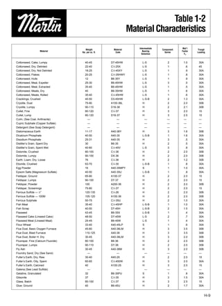
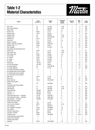
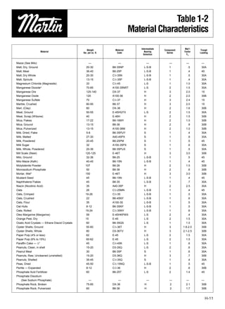
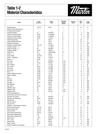
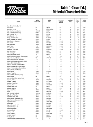
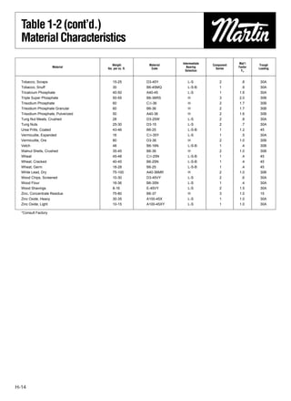
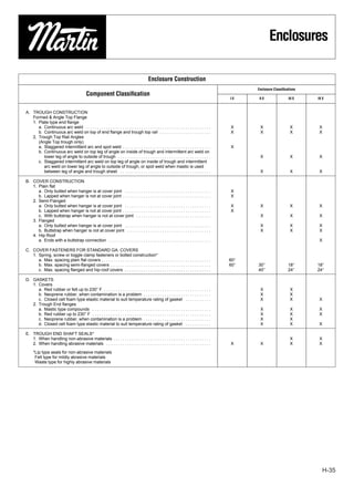
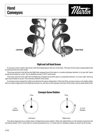
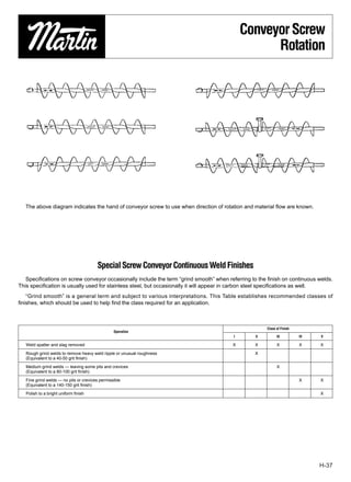
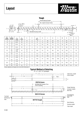
Stock Screw Conveyor
                                                                                                      Components


Martin  manufactures the most complete line of stock components in the industry. We stock stainless, galvanized, and many other
items that are special order with others in the industry.


            Angle Flanged “U” Trough                          Form Flanged “U” Trough                                  Tubular Housing
            Mild Steel and Galvanized                         Mild Steel and Galvanized                           Mild Steel and Galvanized


                                                                                          Trough Ends                          Thrust Assembly
    Inlets and Discharge Spouts                 Discharge Gate
                                                                                    With and Without Feet                          Type E
     Mild Steel and Galvanized               Flat Rack and Pinion
                                                                                   Mild Steel and Galvanized                   With Drive Shaft


                                       Shaft Seal                                                                                   Shaft Seal
         Shaft Seal                                                  Shaft Seal                      Shaft Seal
                                    Compression Type                                                                             Flanged Product
         Split Gland                                                 Waste Pack                        Plate
                                     Packing Gland                                                                                   Drop-out


                                                                  Helicoid Flighting
                 Helicoid Screws                                                                                          Screws
                                                             Right Hand and Left Hand
            Right Hand and Left Hand                                                                               Hot-Dipped Galvanized
                                                            Mild Steel and Stainless Steel


                                                                                                                                                   H-1c
Stock Screw Conveyor
 Components


                                                       Tail, Coupling
       Sectional Flights
                                                      and Drive Shafts


          Hanger                       Hanger
         Style 220                    Style 226                      Hanger                        Hanger                    Hanger
       Mild Steel and               Mild Steel and                  Style 216                      Style 70                 Style 19B
        Galvanized                   Galvanized


        Hanger Bearings
         Style 220/226
                                              Hanger Bearings                      Trough End Bearings                Saddles and Feet
       Martin Hard Iron                          Style 216                            Ball and Roller
       Martin Bronze                             Hard Iron
                                                  UHMW
            UHMW                                  Wood
           Nylatron®
            Wood


                                                                 Shaft-Mounted
             Screw Conveyor Drive                                                                              Flanged Cover
                                                                Speed Reducer
               with Accessories                                                                               with Accessories
                                                                with Accessories


H-1d
Made-To-Order
                                                                                                                                               Conveyors


                                   Stainless Steel Rotor                                                                       60 Inch Diameter Stainless Steel
                        After Shot Peening. Used in the Bleaching                                                              Steaming Vessel Screw Used in
                              Process in a Pulp & Paper Mill.                                                                       Handling Wood Chips.


                Rotory Screen Separator                                     Special Offset Stainless Steel Hanger                                   Elevator Buckets
               For Making Commercial Ice.                                   Used in Handling Various Chemicals.


                              USDA Approved Stainless Steel                                                              Test Facility. an Added Customer Service.
                               Screw Conveyor for Handling                                                             This Area is Available to Check the Conveying
                                Hamburger Meat in a Food                                                                  Characteristics of Customers’ Materials.
                                    Processing Plant.


*Conveyors showh without cover for illustration purposes only. Please follow manufacturing safety guidelines when operating conveyors.                                 H-1e
Special Tolerance
 Requirements
Our association with research and development personnel,
plant engineers and food specialists has offered the
challenge to Martin to meet industry’s new close toler-
ances. Here are but a few examples of manufacturing tech-
niques that we practice.


Dynamic/static balancing of screws takes place at one of Martin’s manufacturing facilities.                           Inspecting total indicated runout of vertical screws.


Stainless steel screw conveyor unit for breakfast cereal plant is checked before a           All stainless steel surfaces of screw and trough can be polished after welding to
shipment. The screw O.D. has been machined for close tolerance for assurance of              meet customers’ specific plant needs.
effective cleanout.


H-1f                                                 *Conveyors showh without cover for illustration purposes only. Please follow manufacturing safety guidelines when operating conveyors.
Engineering


                                                             SECTION I
ENGINEERING SECTION I

Screw Conveyor Design Procedure ........................................................................................... H-3
Material Classification Code Chart............................................................................................. H-4
Material Characteristics Tables .................................................................................................. H-5
Selection of Conveyor Size and Speed.................................................................................... H-16
Capacity Factor Tables ............................................................................................................ H-16
Capacity Table ......................................................................................................................... H-17
Lump Size Limitations and Table ............................................................................................. H-18
Component Group Selection.................................................................................................... H-20
Hanger Bearing Selection ........................................................................................................ H-21
Horsepower Calculation........................................................................................................... H-22
Torsional Ratings of Conveyor Components............................................................................ H-25
Horsepower Ratings of Conveyor Components....................................................................... H-26
Screw Conveyor End Thrust .................................................................................................... H-27
Expansion of Screw Conveyor ................................................................................................. H-28
Screw Conveyor Deflection...................................................................................................... H-29
Inclined Screw Conveyors ....................................................................................................... H-30
Vertical Screw Conveyors ........................................................................................................ H-30
Screw Feeders......................................................................................................................... H-31


                                                                                                                                         H-g
Introduction


Introduction
   The following section is designed to present the necessary engineering information to properly
design and lay out most conveyor applications. The information has been compiled from many
years of experience in successful design and application and from industry standards.
   We hope that the information presented will be helpful to you in determining the type and size of
screw conveyor that will best suit your needs.
   The “Screw Conveyor Design Procedure” on the following page gives ten step-by-step instruc-
tions for properly designing a screw conveyor. These steps, plus the many following tables and for-
mulas throughout the engineering section will enable you to design and detail screw conveyor for
most applications.
   If your requirements present any complications not covered in this section, we invite you to con-
tact our Engineering Department for recommendations and suggestions.


H-2
Design


                              SCREW CONVEYOR DESIGN PROCEDURE

                                 1. Type of material to be conveyed.
                                 2. Maximum size of hard lumps.
          Establish              3. Percentage of hard lumps by volume.
STEP 1    Known                  4. Capacity required, in cu.ft./hr.
          Factors                5. Capacity required, in lbs./hr.
                                 6. Distance material to be conveyed.
                                 7. Any additional factors that may affect conveyor or operations.


          Classify               Classify the material according to the system shown in Table 1-1. Or, if
STEP 2                           the material is included in Table 1-2, use the classification shown in
          Material
                                 Table 1-2.

          Determine
STEP 3    Design                 Determine design capacity as described on pages H-15–H-17.
          Capacity

          Determine
                                 Using known capacity required in cu.ft./hr., material classification, and %
STEP 4    Diameter
                                 trough loading (Table 1-2) determine diameter and speed from Table 1-6.
          and Speed

          Check
          Minimum Screw
                                 Using known screw diameter and percentage of hard lumps, check minimum
STEP 5    Diameter for
                                 screw diameter from Table 1-7.
          Lump Size
          Limitations

          Determine              From Table 1-2, determine hanger bearing group for the material to be
STEP 6    Type of                conveyed. Locate this bearing group in Table 1-11 for the type of bearing
          Bearings               recommended.

                                 From Table 1-2, determine Horsepower Factor “Fm” for the material to be
          Determine
STEP 7                           conveyed. Refer to Page H-22 and calculate horsepower by the formula
          Horsepower
                                 method.

          Check Torsional
          and/or Horsepower
                                 Using required horsepower from step 7 refer to page H-25 and H-26 to check
STEP 8    ratings of
                                 capacities of conveyor pipe, shafts and coupling bolts.
          Conveyor
          Components

                                 Select basic components from Tables 1-8, 1-9, and 1-10 in accordance with
          Select                 Component Group listed in Table 1-2 for the material to be conveyed. Select
STEP 9
          Components             balance of components from the Components Section of catalogue.


          Conveyor
STEP 10                          Refer to page H-38 for typical layout details.
          Layouts


                                                                                                               H-3
Table 1-1
  Material Classification Code Chart

             Major                                                         Code
                             Material Characteristics Included
             Class                                                      Designation


      Density         Bulk Density, Loose                                 Actual
                                                                          Lbs/PC

                                     No. 200 Sieve (.0029″) And Under     A 200
                      Very Fine      No. 100 Sieve (.0059″) And Under     A 100
                                     No. 40 Sieve (.016″) And Under       A 40

                      Fine           No.    6 Sieve (.132″) And Under     B6

                                     1
                                      ⁄2″ And Under (6 Sieve to 1⁄2″)     C 1⁄2
      Size            Granular       3″ And Under (1⁄2 to 3″)             D3
                                     7″ And Under (3″ to 7″)              D7

                                     16″ And Under (0″ to 16″)            D 16
                      Lumpy          Over 16″ To Be Specified
                                       X=Actual Maximum Size              DX

                      Irregular      Stringy, Fibrous, Cylindrical,       E
                                        Slabs, Etc.

                      Very Free Flowing                                   1
                      Free Flowing                                        2
      Flowability
                      Average Flowability                                 3
                      Sluggish                                            4

                      Mildly Abrasive                                     5
      Abrasiveness    Moderately Abrasive                                 6
                      Extremely Abrasive                                  7

                      Builds Up and Hardens                               F
                      Generates Static Electricity                        G
                      Decomposes — Deteriorates in Storage                H
                      Flammability                                        J
                      Becomes Plastic or Tends to Soften                  K
                      Very Dusty                                          L
                      Aerates and Becomes a Fluid                         M
      Miscellaneous   Explosiveness                                       N
                      Stickiness — Adhesion                               O
      Properties      Contaminable, Affecting Use                         P
                      Degradable, Affecting Use                           Q
      Or
                      Gives Off Harmful or Toxic Gas or Fumes             R
      Hazards         Highly Corrosive                                    S
                      Mildly Corrosive                                    T
                      Hygroscopic                                         U
                      Interlocks, Mats or Agglomerates                    V
                      Oils Present                                        W
                      Packs Under Pressure                                X
                      Very Light and Fluffy — May Be Windswept            Y
                      Elevated Temperature                                Z


H-4
Table 1-2
                                                                               Material Characteristics

Material Characteristics
The material characteristics table lists the following Design Data for many materials.
   A. The weight per cubic foot data may be used to calculate the required capacity of the conveyor in either cubic feet per hour or
      pounds per hour.
   B. The material code for each material is as described in Table 1-1, and as interpreted below.
   C. The Intermediate Bearing Selection Code is used to properly select the intermediate hanger bearing from Table 1-11.
   D. The Component Series Code is used to determine the correct components to be used as shown on page H-20.
   E. The Material Factor Fm is used in determining horsepower as described on pages H-22 and H-23.
   F. The Trough Loading column indicates the proper percent of cross section loading to use in determining diameter and speed of
       the conveyor.
For screw conveyor design purposes, conveyed materials are classified in accordance with the code system in Table 1-1, and listed
in Table 1-2.
Table 1-2 lists many materials that can be effectively conveyed by a screw conveyor. If a material is not listed in Table 1-2, it must
be classified according to Table 1-1 or by referring to a listed material similar in weight, particle size and other characteristics.


                                              HOW TO READ THE MATERIAL CODE

                                                         FROM TABLE 1-2


                                                Material: Brewers Grain Spent Wet


                                              C1⁄2            4           5              T

                                                                                             Other
                                 Size                                                        Characteristics


                                                Flowability                   Abrasiveness


                                                                                                                                 H-5
Table 1-2
  Material Characteristics
                                                                            Intermediate               Mat’l
                                             Weight             Material                   Component            Trough
                     Material                                                  Bearing                 Factor
                                         lbs. per cu. ft.        Code                        Series             Loading
                                                                              Selection                  Fm


  Adipic Acid                              45                 A 100-35        S                2         .5      30A
  Alfalfa Meal                             14-22              B6-45WY         H                2         .6      30A
  Alfalfa Pellets                          41-43              C1⁄2-25         H                2         .5      45
  Alfalfa Seed                             10-15              B6-15N          L-S-B            1         .4      45
  Almonds, Broken                          27-30              C1⁄2-35Q        H                2         .9      30A
  Almonds, Whole Shelled                   28-30              C1⁄2-35Q        H                2         .9      30A
  Alum, Fine                               45-50              B6-35U          L-S-B            1         .6      30A
  Alum, Lumpy                              50-60              B6-25           L-S              2        1.4      45
  Alumina                                  55-65              B6-27MY         H                3        1.8      15
  Alumina, Fine                            35                 A100-27MY       H                3        1.6      15
  Alumina Sized Or Briquette               65                 D3-37           H                3        2.0      15
  Aluminate Gel (Aluminate Hydroxide)      45                 B6-35           H                2        1.7      30A
  Aluminum Chips, Dry                      7-15               E-45V           H                2        1.2      30A
  Aluminum Chips, Oily                     7-15               E-45V           H                2         .8      30A
  Aluminum Hydrate                         13-20              C1⁄2-35         L-S-B            1        1.4      30A
  Aluminum Ore (See Bauxite)                  —                     —          —               —        —        —
  Aluminum Oxide                            60-120            A100-17M        H                3        1.8      15
  Aluminum Silicate (Andalusite)            49                C1⁄2-35S        L-S              3         .8      30A
  Aluminum Sulfate                          45-58             C1⁄2-25         L-S-B            1        1.0      45
  Ammonium Chloride, Crystalline            45-52             A100-45FRS      L-S              3         .7      30A
  Ammonium Nitrate                          45-62             A40-35NTU       H                3        1.3      30A
  Ammonium Sulfate                          45-58             C1⁄2-35FOTU     L-S              1        1.0      30A
  Antimony Powder                             —               A100-35         H                2        1.6      30A
  Apple Pomace, Dry                         15                C1⁄2-45Y        H                2        1.0      30A
  Arsenate Of Lead (See Lead Arsenate)        —                     —          —               —        —        —
  Arsenic Oxide (Arsenolite)                100-120         A100-35R          L-S-B            —        —        30A
  Arsenic Pulverized                        30                A100-25R        H                2         .8      45
  Asbestos — Rock (Ore)                     81                D3-37R          H                3        1.2      15
  Asbestos — Shredded                       20-40             E-46XY          H                2        1.0      30B
  Ash, Black Ground                         105               B6-35           L-S-B            1        2.0      30A
  Ashes, Coal, Dry — 1⁄2″                   35-45             C1⁄2-46TY       H                3        3.0      30B
  Ashes, Coal, Dry — 3″                     35-40             D3-46T          H                3        2.5      30B
  Ashes, Coal, Wet — 1⁄2″                   45-50             C1⁄2-46T        H                3        3.0      30B
  Ashes, Coal, Wet — 3″                     45-50             D3-46T          H                3        4.0      30B
  Ashes, Fly (See Fly Ash)                    —                     —          —               —        —        —
  Asphalt, Crushed — 1⁄2″                   45                C1⁄2-45         H                2        2.0      30A
  Bagasse                                   7-10              E-45RVXY        L-S-B            2        1.5      30A
  Bakelite, Fine                            30-45             B6-25           L-S-B            1        1.4      45
  Baking Powder                             40-55             A100-35         S                1         .6      30A
  Baking Soda (Sodium Bicarbonate)          40-55             A100-25         S                1         .6      45
  Barite (Barium Sulfate) + 1⁄2″ — 3″       120-180           D3-36           H                3        2.6      30B
  Barite, Powder                            120-180           A100-35X        H                2        2.0      30A
  Barium Carbonate                          72                A100-45R        H                2        1.6      30A
  Bark, Wood, Refuse                        10-20             E-45TVY         H                3        2.0      30A
  Barley, Fine, Ground                      24-38             B6-35           L-S-B            1         .4      30A
  Barley, Malted                            31                C1⁄2-35         L-S-B            1         .4      30A
  Barley, Meal                              28                C1⁄2-35         L-S-B            1         .4      30A
  Barley, Whole                             36-48             B6-25N          L-S-B            1         .5      45
  Basalt                                    80-105            B6-27           H                3        1.8      15
  Bauxite, Dry, Ground                      68                B6-25           H                2        1.8      45
  Bauxite, Crushed — 3″                     75-85             D3-36           H                3        2.5      30B
  Beans,Castor, Meal                        35-40             B6-35W          L-S-B            1         .8      30A
  Beans, Castor, Whole Shelled              36                C1⁄2-15W        L-S-B            1         .5      45
  Beans, Navy, Dry                          48                C1⁄2-15         L-S-B            1         .5      45
  Beans, Navy, Steeped                      60                C1⁄2-25         L-S-B            1         .8      45


H-6
Table 1-2
                                                                         Material Characteristics
                                                                             Intermediate               Mat’l
                                             Weight           Material                      Component            Trough
                      Material                                                  Bearing                 Factor
                                         lbs. per cu. ft.      Code                           Series             Loading
                                                                               Selection                  Fm


Bentonite, Crude                            34-40           D3-45X             H                2        1.2      30A
Bentonite, –100 Mesh                        50-60           A100-25MXY         H                2         .7      45
Benzene Hexachloride                        56              A100-45R           L-S-B            1         .6      30A
Bicarbonate of Soda (Baking Soda)            —                    —            S                1         .6      —
Blood, Dried                                35-45           D3-45U             H                2        2.0      30A
Blood, Ground, Dried                        30              A100-35U           L-S              1        1.0      30A
Bone Ash (Tricalcium Phosphate)             40-50           A100-45            L-S              1        1.6      30A
Boneblack                                   20-25           A100-25Y           L-S              1        1.5      45
Bonechar                                    27-40           B6-35              L-S              1        1.6      30A
Bonemeal                                    50-60           B6-35              H                2        1.7      30A
Bones, Whole*                               35-50           E-45V              H                2        3.0      30A
Bones, Crushed                              35-50           D3-45              H                2        2.0      30A
Bones, Ground                               50              B6-35              H                2        1.7      30A
Borate of Lime                              60              A100-35            L-S-B            1         .6      30A
Borax, Fine                                 45-55           B6-25T             H                3         .7      30B
Borax Screening — 1⁄2″                      55-60           C1⁄2-35            H                2        1.5      30A
Borax, 11⁄2-2″ Lump                         55-60           D3-35              H                2        1.8      30A
Borax, 2″-3″ Lump                           60-70           D3-35              H                2        2.0      30A
Boric Acid, Fine                            55              B6-25T             H                3         .8      30A
Boron                                       75              A100-37            H                2        1.0      30B
Bran, Rice — Rye — Wheat                    16-20           B6-35NY            L-S-B            1         .5      30A
Braunite (Manganese Oxide)                  120             A100-36            H                2        2.0      30B
Bread Crumbs                                20-25           B6-35PQ            L-S-B            1         .6      30A
Brewer’s Grain, Spent, Dry                  14-30           C1⁄2-45            L-S-B            1         .5      30A
Brewer’s Grain, Spent, Wet                  55-60           C1⁄2-45T           L-S              2         .8      30A
Brick, Ground — 1⁄8″                        100-120         B6-37              H                3        2.2      15
Bronze Chips                                30-50           B6-45              H                2        2.0      30A
Buckwheat                                   37-42           B6-25N             L-S-B            1         .4      45
Calcine, Flour                              75-85           A100-35            L-S-B            1         .7      30A
Calcium Carbide                             70-90           D3-25N             H                2        2.0      30A
Calcium Carbonate (See Limestone)              —                  —             —               —        —         —
Calcium Fluoride (See Fluorspar)               —                  —             —               —        —         —
Calcium Hydrate (See Lime, Hydrated)           —                  —             —               —        —         —
Calcium Hydroxide (See Lime, Hydrated)         —                  —             —               —        —         —
Calcium Lactate                             26-29           D3-45QTR           L-S              2         .6      30A
Calcium Oxide (See Lime, Unslaked)             —                  —             —               —        —         —
Calcium Phosphate                           40-50           A100-45            L-S-B            1        1.6      30A
Calcium Sulfate (See Gypsum)                   —                  —             —               —        —         —
Carbon, Activated, Dry Fine*                   —                  —             —               —        —         —
Carbon Black, Pelleted*                        —                  —             —               —        —         —
Carbon Black, Powder*                          —                  —             —               —        —         —
Carborundum                                 100             D3-27              H                3        3.0      15
Casein                                      36              B6-35              H                2        1.6      30A
Cashew Nuts                                 32-37           C1⁄2-45            H                2         .7      30A
Cast Iron, Chips                            130-200         C1⁄2-45            H                2        4.0      30A
Caustic Soda                                88              B6-35RSU           H                3        1.8      30A
Caustic Soda, Flakes                        47              C1⁄2-45RSUX        L-S              3        1.5      30A
Celite (See Diatomaceous Earth)                —                  —             —               —        —         —
Cement, Clinker                             75-95           D3-36              H                3        1.8      30B
Cement, Mortar                              133             B6-35Q             H                3        3.0      30A
Cement, Portland                            94              A100-26M           H                2        1.4      30B
Cement, Aerated (Portland)                  60-75           A100-16M           H                2        1.4      30B
Cerrusite (See Lead Carbonate)               —                    —             —               —        —        —
Chalk, Crushed                              75-95           D3-25              H                2        1.9      30A
Chalk, Pulverized                           67-75           A100-25MXY         H                2        1.4      45
Charcoal, Ground                            18-28           A100-45            H                2        1.2      30A


                                                                                                                        H-7
Table 1-2
  Material Characteristics
                                                                            Intermediate               Mat’l
                                                 Weight          Material                  Component            Trough
                    Material                                                   Bearing                 Factor
                                             lbs. per cu. ft.     Code                       Series             Loading
                                                                              Selection                  Fm


  Charcoal, Lumps                               18-28           D3-45Q        H                2        1.4      30A
  Chocolate, Cake Pressed                       40-45           D3-25         S                2        1.5      30A
  Chrome Ore                                    125-140         D3-36         H                3        2.5      30B
  Cinders, Blast Furnace                        57              D3-36T        H                3        1.9      30B
  Cinders, Coal                                 40              D3-36T        H                3        1.8      30B
  Clay (See Bentonite, Diatomaceous Earth,
      Fuller’s Earth, Kaolin & Marl)             —                    —        —               —        —        —
  Clay, Ceramic, Dry, Fines                     60-80           A100-35P      L-S-B            1        1.5      30A
  Clay, Calcined                                80-100          B6-36         H                3        2.4      30B
  Clay, Brick, Dry, Fines                       100-120         C1⁄2-36       H                3        2.0      30B
  Clay, Dry, Lumpy                              60-75           D3-35         H                2        1.8      30A
  Clinker, Cement (See Cement Clinker)            —                   —        —               —        —        —
  Clover Seed                                   45-48           B6-25N        L-S-B            1         .4      45
  Coal, Anthracite (River & Culm)               55-61           B6-35TY       L-S              2        1.0      30A
  Coal, Anthracite, Sized-1⁄2″                  49-61           C1⁄2-25       L-S              2        1.0      45
  Coal, Bituminous, Mined                       40-60           D3-35LNXY     L-S              1         .9      30A
  Coal, Bituminous, Mined, Sized                45-50           D3-35QV       L-S              1        1.0      30A
  Coal, Bituminous, Mined, Slack                43-50           C1⁄2-45T      L-S              2         .9      30A
  Coal, Lignite                                 37-45           D3-35T        H                2        1.0      30A
  Cocoa Beans                                   30-45           C1⁄2-25Q      L-S              1         .5      45
  Cocoa, Nibs                                   35              C1⁄2-25       H                2         .5      45
  Cocoa, Powdered                               30-35           A100-45XY     S                1         .9      30A
  Cocoanut, Shredded                            20-22           E-45          S                2        1.5      30A
  Coffee, Chaff                                 20              B6-25MY       L-S              1        1.0      45
  Coffee, Green Bean                            25-32           C1⁄2-25PQ     L-S              1         .5      45
  Coffee, Ground, Dry                           25              A40-35P       L-S              1         .6      30A
  Coffee, Ground, Wet                           35-45           A40-45X       L-S              1         .6      30A
  Coffee, Roasted Bean                          20-30           C1⁄2-25PQ     S                1         .4      45
  Coffee, Soluble                               19              A40-35PUY     S                1         .4      45
  Coke, Breeze                                  25-35           C1⁄2-37       H                3        1.2      15
  Coke, Loose                                   23-35           D7-37         H                3        1.2      15
  Coke, Petrol, Calcined                        35-45           D7-37         H                3        1.3      15
  Compost                                       30-50           D7-45TV       L-S              3        1.0      30A
  Concrete, Pre-Mix Dry                         85-120          C1⁄2-36U      H                3        3.0      30B
  Copper Ore                                    120-150         DX-36         H                3        4.0      30B
  Copper Ore, Crushed                           100-150         D3-36         H                3        4.0      30B
  Copper Sulphate, (Bluestone)                  75-95           C1⁄2-35S      L-S              2        1.0      30A
  Copperas (See Ferrous Sulphate)                 —                   —        —               —        —        —
  Copra, Cake Ground                            40-45           B6-45HW       L-S-B            1         .7      30A
  Copra, Cake, Lumpy                            25-30           D3-35HW       L-S-B            2         .8      30A
  Copra, Lumpy                                  22              E-35HW        L-S-B            2        1.0      30A
  Copra, Meal                                   40-45           B6-35HW       H                2         .7      30A
  Cork, Fine Ground                             5-15            B6-35JNY      L-S-B            1         .5      30A
  Cork, Granulated                              12-15           C1⁄2-35JY     L-S-B            1         .5      30A
  Corn, Cracked                                 40-50           B6-25P        L-S-B            1         .7      45
  Corn Cobs, Ground                             17              C1⁄2-25Y      L-S-B            1         .6      45
  Corn Cobs, Whole*                             12-15           E-35          L-S              2                 30A
  Corn Ear*                                     56              E-35          L-S              2                 30A
  Corn Germ                                     21              B6-35PY       L-S-B            1         .4      30A
  Corn Grits                                    40-45           B6-35P        L-S-B            1         .5      30A
  Cornmeal                                      32-40           B6-35P        L-S              1         .5      30A
  Corn Oil, Cake                                25              D7-45HW       L-S              1         .6      30A
  Corn Seed                                     45              C1⁄2-25PQ     L-S-B            1         .4      45
  Corn Shelled                                  45              C1⁄2-25       L-S-B            1         .4      45
  Corn Sugar                                    30-35           B6-35PU       S                1        1.0      30A
  Cottonseed, Cake, Crushed                     40-45           C1⁄2-45HW     L-S              1        1.0      30A


H-8
Table 1-2
                                                                     Material Characteristics
                                                                         Intermediate               Mat’l
                                         Weight           Material                      Component            Trough
                   Material                                                 Bearing                 Factor
                                     lbs. per cu. ft.      Code                           Series             Loading
                                                                           Selection                  Fm


Cottonseed, Cake, Lumpy                 40-45           D7-45HW            L-S              2        1.0      30A
Cottonseed, Dry, Delinted               22-40           C1⁄2-25X           L-S              1         .6      45
Cottonseed, Dry, Not Delinted           18-25           C1⁄2-45XY          L-S              1         .9      30A
Cottonseed, Flakes                      20-25           C1⁄2-35HWY         L-S              1         .8      30A
Cottonseed, Hulls                       12              B6-35Y             L-S              1         .9      30A
Cottonseed, Meal, Expeller              25-30           B6-45HW            L-S              3         .5      30A
Cottonseed, Meal, Extracted             35-40           B6-45HW            L-S              1         .5      30A
Cottonseed, Meats, Dry                  40              B6-35HW            L-S              1         .6      30A
Cottonseed, Meats, Rolled               35-40           C1⁄2-45HW          L-S              1         .6      30A
Cracklings, Crushed                     40-50           D3-45HW            L-S-B            2        1.3      30A
Cryolite, Dust                          75-90           A100-36L           H                2        2.0      30B
Cryolite, Lumpy                         90-110          D16-36             H                2        2.1      30B
Cullet, Fine                            80-120          C1⁄2-37            H                3        2.0      15
Cullet, Lump                            80-120          D16-37             H                3        2.5      15
Culm, (See Coal, Anthracite)             —                    —             —               —        —        —
Cupric Sulphate (Copper Sulfate)         —                    —             —               —        —        —
Detergent (See Soap Detergent)           —                    —             —               —        —        —
Diatomaceous Earth                      11-17           A40-36Y            H                3        1.6      30B
Dicalcium Phosphate                     40-50           A40-35             L-S-B            1        1.6      30A
Disodium Phosphate                      25-31           A40-35             H                3         .5      30A
Distiller’s Grain, Spent Dry            30              B6-35              H                2         .5      30A
Distiller’s Grain, Spent Wet            40-60           C1⁄2-45V           L-S              3         .8      30A
Dolomite, Crushed                       80-100          C1⁄2-36            H                2        2.0      30B
Dolomite, Lumpy                         90-100          DX-36              H                2        2.0      30B
Earth, Loam, Dry, Loose                 76              C1⁄2-36            H                2        1.2      30B
Ebonite, Crushed                        63-70           C1⁄2-35            L-S-B            1         .8      30A
Egg Powder                              16              A40-35MPY          S                1        1.0      30A
Epsom Salts (Magnesium Sulfate)         40-50           A40-35U            L-S-B            1         .8      30A
Feldspar, Ground                        65-80           A100-37            H                2        2.0      15
Feldspar, Lumps                         90-100          D7-37              H                2        2.0      15
Feldspar, Powder                        100             A200-36            H                2        2.0      30B
Feldspar, Screenings                    75-80           C1⁄2-37            H                2        2.0      15
Ferrous Sulfide — 1⁄2”                   120-135         C1⁄2-26            H                2        2.0      30B
Ferrous Sulfide — 100M                   105-120         A100-36            H                2        2.0      30B
Ferrous Sulphate                        50-75           C1⁄2-35U           H                2        1.0      30A
Fish Meal                               35-40           C1⁄2-45HP          L-S-B            1        1.0      30A
Fish Scrap                              40-50           D7-45H             L-S-B            2        1.5      30A
Flaxseed                                43-45           B6-35X             L-S-B            1         .4      30A
Flaxseed Cake (Linseed Cake)            48-50           D7-45W             L-S              2         .7      30A
Flaxseed Meal (Linseed Meal)            25-45           B6-45W             L-S              1         .4      30A
Flour Wheat                             33-40           A40-45LP           S                1         .6      30A
Flue Dust, Basic Oxygen Furnace         45-60           A40-36LM           H                3        3.5      30B
Flue Dust, Blast Furnace                110-125         A40-36             H                3        3.5      30B
Flue Dust, Boiler H. Dry                30-45           A40-36LM           H                3        2.0      30B
Fluorspar, Fine (Calcium Fluoride)      80-100          B6-36              H                2        2.0      30B
Fluorspar, Lumps                        90-110          D7-36              H                2        2.0      30B
Fly Ash                                 30-45           A40-36M            H                3        2.0      30B
Foundry Sand, Dry (See Sand)             —                    —             —               —        —        —
Fuller’s Earth, Dry, Raw                30-40           A40-25             H                2        2.0      15
Fuller’s Earth, Oily, Spent             60-65           C1⁄2-450W          H                3        2.0      30A
Fuller’s Earth, Calcined                40              A100-25            H                3        2.0      15
Galena (See Lead Sulfide)                 —                    —             —               —        —        —
Gelatine, Granulated                    32              B6-35PU            S                1         .8      30A
Gilsonite                               37              C1⁄2-35            H                3        1.5      30A
Glass, Batch                            80-100          C1⁄2-37            H                3        2.5      15
Glue, Ground                            40              B6-45U             H                2        1.7      30A


                                                                                                                    H-9
Table 1-2
  Material Characteristics
                                                                        Intermediate               Mat’l
                                            Weight          Material                   Component             Trough
                    Material                                               Bearing                 Factor
                                        lbs. per cu. ft.     Code                        Series              Loading
                                                                          Selection                  Fm


  Glue, Pearl                              40              C1⁄2-35U       L-S-B            1          .5      30A
  Glue, Veg. Powdered                      40              A40-45U        L-S-B            1          .6      30A
  Gluten, Meal                             40              B6-35P         L-S              1          .6      30A
  Granite, Fine                            80-90           C1⁄2-27        H                3         2.5      15
  Grape Pomace                             15-20           D3-45U         H                2         1.4      30A
  Graphite Flake                           40              B6-25LP        L-S-B            1          .5      45
  Graphite Flour                           28              A100-35LMP     L-S-B            1          .5      30A
  Graphite Ore                             65-75           DX-35L         H                2         1.0      30A
  Guano Dry*                               70              C1⁄2-35        L-S              3         2.0      30A
  Gypsum, Calcined                         55-60           B6-35U         H                2         1.6      30A
  Gypsum, Calcined, Powdered               60-80           A100-35U       H                2         2.0      30A
  Gypsum, Raw — 1″                         70-80           D3-25          H                2         2.0      30A
  Hay, Chopped*                            8-12            C1⁄2-35JY      L-S              2         1.6      30A
  Hexanedioic Acid (See Adipic Acid)         —                   —          —              —         —        —
  Hominy, Dry                              35-50           C1⁄2-25        L-S-B            1           .4     45
  Hops, Spent, Dry                         35              D3-35          L-S-B            2         1.0      30A
  Hops, Spent, Wet                         50-55           D3-45V         L-S              2         1.5      30A
  Ice, Crushed                             35-45           D3-35Q         L-S              2           .4     30A
  Ice, Flaked*                             40-45           C1⁄2-35Q       S                1           .6     30A
  Ice, Cubes                               33-35           D3-35Q         S                1           .4     30A
  Ice, Shell                               33-35           D3-45Q         S                1           .4     30A
  Ilmenite Ore                             140-160         D3-37          H                3         2.0      15
  Iron Ore Concentrate                     120-180         A40-37         H                3         2.2      15
  Iron Oxide Pigment                       25              A100-36LMP     H                2         1.0      30B
  Iron Oxide, Millscale                    75              C1⁄2-36        H                2         1.6      30B
  Iron Pyrites (See Ferrous Sulfide)          —                   —          —              —         —        —
  Iron Sulphate (See Ferrous Sulfate)        —                   —          —              —         —        —
  Iron Sulfide (See Ferrous Sulfide)           —                   —          —              —         —        —
  Iron Vitriol (See Ferrous Sulfate)         —                   —          —              —         —        —
  Kafir (Corn)                              40-45           C1⁄2-25        H                3           .5     45
  Kaolin Clay                              63              D3-25          H                2         2.0      30A
  Kaolin Clay-Talc                         32-56           A40-35LMP      H                2         2.0      30A
  Kryalith (See Cryolite)                    —                   —          —              —         —        —
  Lactose                                  32              A40-35PU       S                1           .6     30A
  Lamp Black (See Carbon Black)              —                   —          —              —         —        —
  Lead Arsenate                            72              A40-35R        L-S-B            1         1.4      30A
  Lead Arsenite                            72              A40-35R        L-S-B            1         1.4      30A
  Lead Carbonate                           240-260         A40-35R        H                2         1.0      30A
  Lead Ore — 1⁄8″                          200-270         B6-35          H                3         1.4      30A
  Lead Ore — 1⁄2″                          180-230         C1⁄2-36        H                3         1.4      30B
  Lead Oxide (Red Lead) — 100 Mesh         30-150          A100-35P       H                2         1.2      30A
  Lead Oxide (Red Lead) — 200 Mesh         30-180          A200-35LP      H                2         1.2      30A
  Lead Sulphide — 100 Mesh                 240-260         A100-35R       H                2         1.0      30A
  Lignite (See Coal Lignite)                 —                   —          —              —         —        —
  Limanite, Ore, Brown                     120             C1⁄2-47        H                3         1.7      15
  Lime, Ground, Unslaked                   60-65           B6-35U         L-S-B            1           .6     30A
  Lime Hydrated                            40              B6-35LM        H                2           .8     30A
  Lime, Hydrated, Pulverized               32-40           A40-35LM       L-S              1           .6     30A
  Lime, Pebble                             53-56           C1⁄2-25HU      L-S              2         2.0      45
  Limestone, Agricultural                  68              B6-35          H                2         2.0      30A
  Limestone, Crushed                       85-90           DX-36          H                2         2.0      30B
  Limestone, Dust                          55-95           A40-46MY       H                2       1.6-2.0    30B
  Lindane (Benzene Hexachloride)             —                   —          —              —         —        —
  Linseed (See Flaxseed)                     —                   —          —              —         —        —
  Litharge (Lead Oxide)                      —                   —          —              —         —        —
  Lithopone                                45-50           A325-35MR      L-S              1         1.0      30A


H-10
Table 1-2
                                                                               Material Characteristics
                                                                                   Intermediate                Mat’l
                                                    Weight          Material                      Component             Trough
                   Material                                                           Bearing                  Factor
                                                lbs. per cu. ft.     Code                           Series              Loading
                                                                                     Selection                   Fm


Maize (See Milo)                                    —                    —             —              —         —        —
Malt, Dry, Ground                                  20-30           B6-35NP           L-S-B            1          .5      30A
Malt, Meal                                         36-40           B6-25P            L-S-B            1          .4      45
Malt, Dry Whole                                    20-30           C1⁄2-35N          L-S-B            1          .5      30A
Malt, Sprouts                                      13-15           C1⁄2-35P          L-S-B            1          .4      30A
Magnesium Chloride (Magnesite)                     33              C1⁄2-45           L-S              1         1.0      30A
Manganese Dioxide*                                 70-85           A100-35NRT        L-S              2         1.5      30A
Manganese Ore                                      125-140         DX-37             H                3         2.0      15
Manganese Oxide                                    120             A100-36           H                2         2.0      30B
Manganese Sulfate                                  70              C1⁄2-37           H                3         2.4      15
Marble, Crushed                                   80-95            B6-37             H                3         2.0      15
Marl, (Clay)                                      80               DX-36             H                2         1.6      30B
Meat, Ground                                      50-55            E-45HQTX          L-S              2         1.5      30A
Meat, Scrap (Wbone)                              40               E-46H             H                2         1.5      30B
Mica, Flakes                                      17-22            B6-16MY           H                2         1.0      30B
Mica, Ground                                      13-15            B6-36             H                2           .9     30B
Mica, Pulverized                                  13-15            A100-36M          H                2         1.0      30B
Milk, Dried, Flake                                5-6              B6-35PUY          S                1           .4     30A
Milk, Malted                                      27-30            A40-45PX          S                1           .9     30A
Milk, Powdered                                    20-45            B6-25PM           S                1           .5     45
Milk Sugar                                        32               A100-35PX         S                1           .6     30A
Milk, Whole, Powdered                             20-36            B6-35PUX          S                1           .5     30A
Mill Scale (Steel)                                120-125          E-46T             H                3         3.0      30B
Milo, Ground                                      32-36            B6-25             L-S-B            1           .5     45
Milo Maize (Kafir)                                 40-45            B6-15N            L-S-B            1           .4     45
Molybdenite Powder                                107              B6-26             H                2         1.5      30B
Monosodium Phosphate                              50               B6-36             H                2           .6     30B
Mortar, Wet*                                      150              E-46T             H                3         3.0      30B
Mustard Seed                                      45               B6-15N            L-S-B            1           .4     45
Naphthalene Flakes                                45               B6-35             L-S-B            1           .7     30A
Niacin (Nicotinic Acid)                           35               A40-35P           H                2         2.5      30A
Oats                                              26               C1⁄2-25MN         L-S-B            1           .4     45
Oats, Crimped                                     19-26            C1⁄2-35           L-S-B            1           .5     30A
Oats, Crushed                                     22               B6-45NY           L-S-B            1           .6     30A
Oats, Flour                                       35               A100-35           L-S-B            1           .5     30A
Oat Hulls                                         8-12             B6-35NY           L-S-B            1           .5     30A
Oats, Rolled                                      19-24            C1⁄2-35NY         L-S-B            1           .6     30A
Oleo Margarine (Margarine)                        59               E-45HKPWX         L-S              2           .4     30A
Orange Peel, Dry                                  15               E-45              L-S              2         1.5      30A
Oxalic Acid Crystals — Ethane Diacid Crystals     60               B6-35QS           L-S              1         1.0      30A
Oyster Shells, Ground                             50-60            C1⁄2-36T          H                3       1.6-2.0    30B
Oyster Shells, Whole                              80               D3-36TV           H                3       2.1-2.5    30B
Paper Pulp (4% or less)                           62               E-45              L-S              2         1.5      30A
Paper Pulp (6% to 15%)                            60-62            E-45              L-S              2         1.5      30A
Paraffin Cake — 1⁄2″                               45               C1⁄2-45K          L-S              1           .6     30A
Peanuts, Clean, in shell                          15-20            D3-35Q            L-S              2           .6     30A
Peanut Meal                                       30               B6-35P            S                1           .6     30A
Peanuts, Raw, Uncleaned (unshelled)               15-20            D3-36Q            H                3           .7     30B
Peanuts, Shelled                                  35-45            C1⁄2-35Q          S                1           .4     30A
Peas, Dried                                       45-50            C1⁄2-15NQ         L-S-B            1           .5     45
Perlite — Expanded                                8-12             C1⁄2-36           H                2           .6     30B
Phosphate Acid Fertillizer                        60               B6-25T            L-S              2         1.4      45
Phosphate Disodium
     (See Sodium Phosphate)                         —                  —              —               —         —        —
Phosphate Rock, Broken                             75-85           DX-36             H                2         2.1      30B
Phosphate Rock, Pulverized                         60              B6-36             H                2         1.7      30B


                                                                                                                            H-11
Table 1-2
  Material Characteristics
                                                                        Intermediate               Mat’l
                                            Weight          Material                   Component            Trough
                     Material                                              Bearing                 Factor
                                        lbs. per cu. ft.     Code                        Series             Loading
                                                                          Selection                  Fm


  Phosphate Sand                           90-100          B6-37          H                3        2.0      15
  Plaster of Paris (See Gypsum)             —                    —         —               —        —        —
  Plumbago (See Graphite)                   —                    —         —               —        —        —
  Polystyrene Beads                        40              B6-35PQ        S                1         .4      30A
  Polyvinyl, Chloride Powder               20-30           A100-45KT      S                2        1.0      30A
  Polyvinyl, Chloride Pellets              20-30           E-45KPQT       S                1         .6      30A
  Polyethylene, Resin Pellets              30-35           C1⁄2-45Q       L-S              1         .4      30A
  Potash (Muriate) Dry                     70              B6-37          H                3        2.0      15
  Potash (Muriate) Mine Run                75              DX-37          H                3        2.2      15
  Potassium Carbonate                      51              B6-36          H                2        1.0      30B
  Potassium Chloride Pellets               120-130         C1⁄2-25TU      H                3        1.6      45
  Potassium Nitrate — 1⁄2″                 76              C1⁄2-16NT      H                3        1.2      30B
  Potassium Nitrate — 1⁄8″                 80              B6-26NT        H                3        1.2      30B
  Potassium Sulfate                        42-48           B6-46X         H                2        1.0      30B
  Potato Flour                             48              A200-35MNP     L-S              1         .5      30A
  Pumice — 1⁄8″                            42-48           B6-46          H                3        1.6      30B
  Pyrite, Pellets                          120-130         C1⁄2-26        H                3        2.0      30B
  Quartz — 100 Mesh                        70-80           A100-27        H                3        1.7      15
  Quartz — 1⁄2″                            80-90           C1⁄2-27        H                3        2.0      15
  Rice, Bran                               20              B6-35NY        L-S-B            1         .4      30A
  Rice, Grits                              42-45           B6-35P         L-S-B            1         .4      30A
  Rice, Polished                           30              C1⁄2-15P       L-S-B            1         .4      45
  Rice, Hulled                             45-49           C1⁄2-25P       L-S-B            1         .4      45
  Rice, Hulls                              20-21           B6-35NY        L-S-B            1         .4      30A
  Rice, Rough                              32-36           C1⁄2-35N       L-S-B            1         .6      30A
  Rosin — 1⁄2″                             65-68           C1⁄2-45Q       L-S-B            1        1.5      30A
  Rubber, Reclaimed Ground                 23-50           C1⁄2-45        L-S-B            1         .8      30A
  Rubber, Pelleted                         50-55           D3-45          L-S-B            2        1.5      30A
  Rye                                      42-48           B6-15N         L-S-B            1         .4      45
  Rye Bran                                 15-20           B6-35Y         L-S-B            1         .4      45
  Rye Feed                                 33              B6-35N         L-S-B            1         .5      30A
  Rye Meal                                 35-40           B6-35          L-S-B            1         .5      30A
  Rye Middlings                            42              B6-35          L-S              1         .5      30A
  Rye, Shorts                              32-33           C1⁄2-35        L-S              2         .5      30A
  Safflower, Cake                           50              D3-26          H                2         .6      30B
  Safflower, Meal                           50              B6-35          L-S-B            1         .6      30A
  Safflower Seed                            45              B6-15N         L-S-B            1         .4      45
  Saffron (See Safflower)                    —                    —         —               —        —        —
  Sal Ammoniac (Ammonium Chloride)          —                    —         —               —        —        —
  Salt Cake, Dry Coarse                    85              B6-36TU        H                3        2.1      30B
  Salt Cake, Dry Pulverized                65-85           B6-36TU        H                3        1.7      30B
  Salicylic Acid                           29              B6-37U         H                3         .6      15
  Salt, Dry Coarse                         45-60           C1⁄2-36TU      H                3        1.0      30B
  Salt, Dry Fine                           70-80           B6-36TU        H                3        1.7      30B
  Saltpeter — (See Potassium Nitrate)       —                    —         —               —        —        —
  Sand Dry Bank (Damp)                     110-130         B6-47          H                3        2.8      15
  Sand Dry Bank (Dry)                      90-110          B6-37          H                3        1.7      15
  Sand Dry Silica                          90-100          B6-27          H                3        2.0      15
  Sand Foundry (Shake Out)                 90-100          D3-37Z         H                3        2.6      15
  Sand (Resin Coated) Silica               104             B6-27          H                3        2.0      15
  Sand (Resin Coated) Zircon               115             A100-27        H                3        2.3      15
  Sawdust, Dry                             10-13           B6-45UX        L-S-B            1        1.4      15
  Sea — Coal                               65              B6-36          H                2        1.0      30B
  Sesame Seed                              27-41           B6-26          H                2         .6      30B
  Shale, Crushed                           85-90           C1⁄2-36        H                2        2.0      30B
  Shellac, Powdered or Granulated          31              B6-35P         S                1         .6      30A


H-12
Table 1-2 (cont’d.)
                                                                         Material Characteristics
                                                                             Intermediate               Mat’l
                                              Weight          Material                      Component             Trough
                   Material                                                     Bearing                 Factor
                                          lbs. per cu. ft.     Code                           Series              Loading
                                                                               Selection                  Fm


Silicon Dioxide (See Quartz)                  —                    —            —               —         —        —
Silica, Flour                                80              A40-46            H                2         1.5      30B
Silica Gel + 1⁄2″ - 3″                       45              D3-37HKQU         H                3         2.0      15
Slag, Blast Furnace Crushed                  130-180         D3-37Y            H                3         2.4      15
Slag, Furnace Granular, Dry                  60-65           C1⁄2-37           H                3         2.2      15
Slate, Crushed, — 1⁄2″                       80-90           C1⁄2-36           H                2         2.0      30B
Slate, Ground, — 1⁄8″                        82-85           B6-36             H                2         1.6      30B
Sludge, Sewage, Dried                        40-50           E-47TW            H                3          .8      15
Sludge, Sewage, Dry Ground                   45-55           B-46S             H                2          .8      30B
Soap, Beads or Granules                      15-35           B6-35Q            L-S-B            1          .6      30A
Soap, Chips                                  15-25           C1⁄2-35Q          L-S-B            1           .6     30A
Soap Detergent                               15-50           B6-35FQ           L-S-B            1           .8     30A
Soap, Flakes                                 5-15            B6-35QXY          L-S-B            1           .6     30A
Soap, Powder                                 20-25           B6-25X            L-S-B            1           .9     45
Soapstone, Talc, Fine                        40-50           A200-45XY         L-S-B            1         2.0      30A
Soda Ash, Heavy                              55-65           B6-36             H                2         2.0      30B
Soda Ash, Light                              20-35           A40-36Y           H                2         1.6      30B
Sodium Aluminate, Ground                     72              B6-36             H                2         1.0      30B
Sodium Aluminum Fluoride (See Kryolite)        —                   —            —               —         —        —
Sodium Aluminum Sulphate*                    75              A100-36           H                2         1.0      30B
Sodium Bentonite (See Bentonite)               —                   —            —               —         —        —
Sodium Bicarbonate (See Baking Soda)           —                   —            —               —         —        —
Sodium Chloride (See Salt)                     —                   —            —               —         —        —
Sodium Carbonate (See Soda Ash)                —                   —            —               —         —        —
Sodium Hydrate (See Caustic Soda)              —                   —            —               —         —        —
Sodium Hydroxide (See Caustic Soda)            —                   —            —               —         —        —
Sodium Borate (See Borax)                      —                   —            —               —         —        —
Sodium Nitrate                               70-80           D3-25NS           L-S              2         1.2      30A
Sodium Phosphate                             50-60           A-35              L-S              1           .9     30A
Sodium Sulfate (See Salt Cake)                 —                   —            —               —         —        —
Sodium Sulfite                                96              B6-46X            H                2         1.5      30B
Sorghum, Seed (See Kafir or Milo)               —                   —            —               —         —        —
Soybean, Cake                                40-43           D3-35W            L-S-B            2         1.0      30A
Soybean, Cracked                             30-40           C1⁄2-36NW         H                2           .5     30B
Soybean, Flake, Raw                          18-25           C1⁄2-35Y          L-S-B            1           .8     30A
Soybean, Flour                               27-30           A40-35MN          L-S-B            1           .8     30A
Soybean Meal, Cold                           40              B6-35             L-S-B            1           .5     30A
Soybean Meal Hot                             40              B6-35T            L-S              2           .5     30A
Soybeans, Whole                              45-50           C1⁄2-26NW         H                2         1.0      30B
Starch                                       25-50           A40-15M           L-S-B            1         1.0      45
Steel Turnings, Crushed                      100-150         D3-46WV           H                3         3.0      30B
Sugar Beet, Pulp, Dry                        12-15           C1⁄2-26           H                2           .9     30B
Sugar Beet, Pulp, Wet                        25-45           C1⁄2-35X          L-S-B            1         1.2      30A
Sugar, Refined, Granulated Dry                50-55           B6-35PU           S                1       1.0-1.2    30A
Sugar, Refined, Granulated Wet                55-65           C1⁄2-35X          S                1       1.4-2.0    30A
Sugar, Powdered                              50-60           A100-35PX         S                1           .8     30A
Sugar, Raw                                   55-65           B6-35PX           S                1         1.5      30A
Sulphur, Crushed — 1⁄2″                      50-60           C1⁄2-35N          L-S              1           .8     30A
Sulphur, Lumpy, — 3″                         80-85           D3-35N            L-S              2           .8     30A
Sulphur, Powdered                            50-60           A40-35MN          L-S              1           .6     30A
Sunflower Seed                                19-38           C1⁄2-15           L-S-B            1           .5     45
Talcum, — 1⁄2″                               80-90           C1⁄2-36           H                2           .9     30B
Talcum Powder                                50-60           A200-36M          H                2           .8     30B
Tanbark, Ground*                             55              B6-45             L-S-B            1           .7     30A
Timothy Seed                                 36              B6-35NY           L-S-B            1           .6     30A
Titanium Dioxide (See Ilmenite Ore)            —                   —            —               —         —        —


                                                                                                                      H-13
Table 1-2 (cont’d.)
  Material Characteristics
                                                                   Intermediate               Mat’l
                                        Weight          Material                  Component            Trough
                     Material                                         Bearing                 Factor
                                    lbs. per cu. ft.     Code                       Series             Loading
                                                                     Selection                  Fm


  Tobacco, Scraps                       15-25          D3-45Y         L-S             2        .8       30A
  Tobacco, Snuff                        30             B6-45MQ        L-S-B           1        .9       30A
  Tricalcium Phosphate                  40-50          A40-45         L-S             1       1.6       30A
  Triple Super Phosphate                50-55          B6-36RS        H               3       2.0       30B
  Trisodium Phosphate                   60             C1⁄2-36        H               2       1.7       30B
  Trisodium Phosphate Granular          60             B6-36          H               2       1.7       30B
  Trisodium Phosphate, Pulverized       50             A40-36         H               2       1.6       30B
  Tung Nut Meats, Crushed               28             D3-25W         L-S             2        .8       30A
  Tung Nuts                             25-30          D3-15          L-S             2        .7       30A
  Urea Prills, Coated                   43-46          B6-25          L-S-B           1       1.2       45
  Vermiculite, Expanded                 16             C1⁄2-35Y       L-S             1        .5       30A
  Vermiculite, Ore                      80             D3-36          H               2       1.0       30B
  Vetch                                 48             B6-16N         L-S-B           1        .4       30B
  Walnut Shells, Crushed                35-45          B6-36          H               2       1.0       30B
  Wheat                                 45-48          C1⁄2-25N       L-S-B           1        .4       45
  Wheat, Cracked                        40-45          B6-25N         L-S-B           1        .4       45
  Wheat, Germ                           18-28          B6-25          L-S-B           1        .4       45
  White Lead, Dry                       75-100         A40-36MR       H               2       1.0       30B
  Wood Chips, Screened                  10-30          D3-45VY        L-S             2        .6       30A
  Wood Flour                            16-36          B6-35N         L-S             1        .4       30A
  Wood Shavings                         8-16           E-45VY         L-S             2       1.5       30A
  Zinc, Concentrate Residue             75-80          B6-37          H               3       1.0       15
  Zinc Oxide, Heavy                     30-35          A100-45X       L-S             1       1.0       30A
  Zinc Oxide, Light                     10-15          A100-45XY      L-S             1       1.0       30A

  *Consult Factory


H-14
Selection of Conveyor
                                                                                          Size and Speed

   In order to determine the size and speed of a screw conveyor, it is necessary first to establish the material code number. It will be
seen from what follows that this code number controls the cross-sectional loading that should be used. The various cross-sectional
loadings shown in the Capacity Table (Table 1-6) are for use with the standard screw conveyor components indicated in the
Component Group Selection Guide on page H-20 and are for use where the conveying operation is controlled with volumetric feed-
ers and where the material is uniformly fed into the conveyor housing and discharged from it. Check lump size limitations before
choosing conveyor diameter. See Table 1-7.


Capacity Table
    The capacity table, (Table 1-6), gives the capacities in cubic feet per hour at one revolution per minute for various size screw
conveyors for four cross-sectional loadings. Also shown are capacities in cubic feet per hour at the maximum recommended
revolutions per minute.
    The capacity values given in the table will be found satisfactory for most all applications. Where the capacity of a screw conveyor
is very critical, especially when handling a material not listed in Table 1-2, it is best to consult our Engineering Department.
    The maximum capacity of any size screw conveyor for a wide range of materials, and various conditions of loading, may be
obtained from Table 1-6 by noting the values of cubic feet per hour at maximum recommended speed.


Conveyor Speed
   For screw conveyors with screws having standard pitch helical flights the conveyor speed may be calculated by the formula:

                  Required capacity, cubic feet per hour
         N=
              Cubic feet per hour at 1 revolution per minute
         N=      revolutions per minute of screw, (but not
              greater than the maximum recommended speed.)

   For the calculation of conveyor speeds where special types of screws are used, such as short pitch screws, cut flights, cut and
folded flights and ribbon flights, an equivalent required capacity must be used, based on factors in the Tables 1-3, 4, 5.
   Factor CF1 relates to the pitch of the screw. Factor CF2 relates to the type of the flight. Factor CF3 relates to the use of mixing
paddles within the flight pitches.
    The equivalent capacity then is found by multiplying the required capacity by the capacity factors. See Tables 1-3, 4, 5 for
capacity factors.


          (Cubic Feet Per Hour) = (Cubic Feet Capacity ) (CF ) (CF ) (CF )
             Equiv. Capacity        Required
                                              Per Hour             1      2     3


                                                                                                                                 H-15
Capacity
   Factors

                                                                             Table 1-3
                                                               Special Conveyor Pitch Capacity Factor CF1

             Pitch                                                              Description                                             CF1

          Standard                                                    Pitch = Diameter of Screw                                         1.00
          Short                                                       Pitch =2⁄3 Diameter of Screw                                      1.50
          Half                                                        Pitch =1⁄2 Diameter of Screw                                      2.00
          Long                                                        Pitch = 11⁄2 Diameter of Screw                                    0.67


                                                                             Table 1-4
                                                               Special Conveyor Flight Capacity Factor CF2

                                                                                                             Conveyor Loading
                            Type of
                             Flight                                                      15%                       30%                  45%

                     Cut Flight                                                         1.95                       1.57                 1.43
                     Cut & Folded Flight                                                N.R.*                      3.75                 2.54
                     Ribbon Flight                                                      1.04                       1.37                 1.62

*Not recommended
*If none of the above flight modifications are used: CF2 = 1.0


                                                                             Table 1-5
                                                               Special Conveyor Mixing Paddle Capacity CF3

                                                                                                             Paddles Per Pitch
                        Standard Paddles at
                         45° Reverse Pitch                                       None                  1           2              3             4

                             Factor CF3                                          1.00              1.08          1.16            1.24          1.32


H-16
Capacity Table
                                 Horizontal Screw Conveyors
                                                                   (Consult Factory for Inclined Conveyors)


                            Table 1-6
                       Screw                         Capacity Cubic Feet
      Trough Loading    Dia.                         Per Hour (Full Pitch)                        Max.
                        Inch                                                                      RPM
                                        At One RPM                           At Max RPM

                        4                  0.62                                  114             184
                        6                  2.23                                  368             165
                        9                  8.20                                1270              155
                       10                 11.40                                1710              150
                       12                 19.40                                2820              145

45%                    14
                       16
                                          31.20
                                          46.70
                                                                               4370
                                                                               6060
                                                                                                 140
                                                                                                 130
                       18                 67.60                                8120              120
                       20                 93.70                               10300              110
                       24                164.00                               16400              100
                       30                323.00                               29070               90

                        4                  0.41                                   53             130
                        6                  1.49                                  180             120
                        9                  5.45                                  545             100
                       10                  7.57                                  720              95

30%                    12
                       14
                                          12.90
                                          20.80
                                                                               1160
                                                                               1770
                                                                                                  90
                                                                                                  85

 A                     16
                       18
                                          31.20
                                          45.00
                                                                               2500
                                                                               3380
                                                                                                  80
                                                                                                  75
                       20                 62.80                                4370               70
                       24                109.00                                7100               65
                       30                216.00                               12960               60

                        4                  0.41                                   29              72
                        6                  1.49                                   90              60
                        9                  5.45                                  300              55
                       10                  7.60                                  418              55

30%                    12
                       14
                                          12.90
                                          20.80
                                                                                 645
                                                                               1040
                                                                                                  50
                                                                                                  50

 B                     16
                       18
                                          31.20
                                          45.00
                                                                               1400
                                                                               2025
                                                                                                  45
                                                                                                  45
                       20                 62.80                                2500               40
                       24                109.00                                4360               40
                       30                216.00                                7560               35

                        4                  0.21                                   15              72
                        6                  0.75                                   45              60
                        9                  2.72                                  150              55
                       10                  3.80                                  210              55
                       12                  6.40                                  325              50

15%                    14
                       16
                                          10.40
                                          15.60
                                                                                 520
                                                                                 700
                                                                                                  50
                                                                                                  45
                       18                 22.50                                1010               45
                       20                 31.20                                1250               40
                       24                 54.60                                2180               40
                       30                108.00                                3780               35


                                                                                                         H-17
Lump Size
   Limitations
   The size of a screw conveyor not only depends on the capacity required, but also on the size and proportion of lumps in the
material to be handled. The size of a lump is the maximum dimension it has. If a lump has one dimension much longer than its
transverse cross-section, the long dimension or length would determine the lump size.

   The character of the lump also is involved. Some materials have hard lumps that won’t break up in transit through a screw con-
veyor. In that case, provision must be made to handle these lumps. Other materials may have lumps that are fairly hard, but
degradable in transit through the screw conveyor, thus reducing the lump size to be handled. Still other materials have lumps that
are easily broken in a screw conveyor and lumps of these materials impose no limitations.

   Three classes of lump sizes are shown in TABLE 1-7 and as follows

Class 1
   A mixture of lumps and fines in which not more than 10% are lumps ranging from maximum size to one half of the maximum;
and 90% are lumps smaller than one half of the maximum size.
Class 2
   A mixture of lumps and fines in which not more than 25% are lumps ranging from the maximum size to one half of the maximum;
and 75% are lumps smaller than one half of the maximum size.
Class 3
    A mixture of lumps only in which 95% or more are lumps ranging from maximum size to one half of the maximum size; and 5%
or less are lumps less than one tenth of the maximum size.


                                                                           Table 1-7
                                                                  Maximum Lump Size Table
        Screw                     Pipe                        Radial                      Class I              Class II          Class III
       Diameter                  *O.D.                      Clearance                   10% Lumps            25% Lumps         95% Lumps
        Inches                  Inches                       Inches ∆                 Max. Lump, Inch      Max. Lump, Inch   Max. Lump, Inch

          6                      23⁄8                         25⁄16                         11⁄4                 3
                                                                                                                  ⁄4               1
                                                                                                                                    ⁄2
          9                      23⁄8                         33⁄16                         21⁄4                 11⁄2              3
                                                                                                                                    ⁄4
          9                      27⁄8                         39⁄16                         21⁄4                 11⁄2              3
                                                                                                                                    ⁄4

         12                      27⁄8                         51⁄16                         23⁄4                  2                 1
         12                      31⁄2                         43⁄4                          23⁄4                  2                 1
         12                       4                           41⁄2                          23⁄4                  2                 1

         14                      31⁄2                          53⁄4                         31⁄4                 21⁄2              11⁄4
         14                       4                            51⁄2                         21⁄2                 11⁄4              11⁄4

         16                       4                            61⁄2                         33⁄4                 23⁄4              11⁄2
         16                      41⁄2                          61⁄4                         33⁄4                 23⁄4              11⁄2

         18                       4                            71⁄2                         41⁄4                  3                13⁄4
         18                      41⁄2                          71⁄2                         41⁄4                  3                13⁄4

         20                       4                            81⁄2                         43⁄4                 31⁄2               2
         20                      41⁄2                          81⁄4                         43⁄4                 31⁄2               2
         24                      41⁄2                         101⁄4                          6                   33⁄4              21⁄2
         30                      41⁄2                         131⁄4                          8                    5                 3

*For special pipe sizes, consult factory.
∆ Radial clearance is the distance between the bottom of the trough and the bottom of the conveyor pipe.


H-18
Lump Size Limitations
                                                                                 Component Groups
EXAMPLE: Lump Size Limitations
    To illustrate the selection of a conveyor size from the maximum lump size table, table 1-7, consider crushed ice as the conveyed
material. Refer to the material charts table 1-2 and find crushed ice and its material code D3-35-Q and weight of 35-45 lbs./C.F. D3
means that the lump size is 1⁄2″ to 3″, this is noted by referring to the material classification code chart on page H-4. From actual
specifications regarding crushed ice it is known that crushed ice has a maximum lump size of 11⁄2″ and only 25% of the lumps are
11⁄2″. With this information refer to table 1-7, Maximum lump size table. Under the column Class II and 11⁄2″ Max. lump size read
across to the minimum screw diameter which will be 9″.


                                                     Component Groups
    To facilitate the selection of proper specifications for a screw conveyor for a particular duty, screw conveyors are broken down
into three Component Groups. These groups relate both to the Material Classification Code and also to screw size, pipe size, type
of bearings and trough thickness.
    Referring to table 1-2, find the component series designation of the material to be conveyed.
    Having made the Component Series selection, refer to Tables 1-8, 9, 10 which give the specifications of the various sizes of con-
veyor screws. (The tabulated screw numbers in this table refer to standard specifications for screws found on pages H-73–H-75
Component Section.) These standards give complete data on the screws such as the length of standard sections, minimum edge
thickness of screw flight, bushing data, bolt size, bolt spacing, etc.


EXAMPLE: For a screw conveyor to handle brewers grain, spent wet, refer to the material characteristics Table 1-2. Note that the
         component series column refers to series 2. Refer now to page H-20, component selection, Table 1-9, component
         group 2. The standard shaft sizes, screw flight designations, trough gauges and cover gauges are listed for each
         screw diameter.


                                                                                                                               H-19
Component
  Selection

                                            Table 1-8
                                        Component Group 1
        Screw     Coupling                Screw Number                           Thickness, U.S. Standard
       Diameter   Diameter   Helicoid                    Sectional                   Gauge or Inches
        Inches     Inches    Flights                      Flights    Trough                                  Cover

           6        11⁄2     6H304                       6S307       16 Ga.                                 16 Ga.
           9        11⁄2     9H306                       9S307       14 Ga.                                 14 Ga.
           9         2       9H406                       9S409       14 Ga.                                 14 Ga.
         12          2       12H408                      12S409      12 Ga.                                 14 Ga.
         12         27⁄16    12H508                      12S509      12 Ga.                                 14 Ga.
         14         27⁄16    14H508                      14S509      12 Ga.                                 14 Ga.
         16          3       16H610                      16S612      12 Ga.                                 14 Ga.
         18          3         —                         18S612      10 Ga.                                 12 Ga.
         20          3         —                         20S612      10 Ga.                                 12 Ga.
         24         37⁄16      —                         24S712      10 Ga.                                 12 Ga.
         30         37⁄16      —                         30S712      10 Ga.                                 12 Ga.


                                            Table 1-9
                                        Component Group 2
        Screw     Coupling                Screw Number                           Thickness, U.S. Standard
         Dia.       Dia.     Helicoid                    Sectional                   Gauge or Inches
        Inches     Inches    Flights                      Flights    Trough                                  Cover

           6        11⁄2     6H308                       6S309       14 Ga..                            16 Ga..
           9        11⁄2     9H312                       9S309       10 Ga.                             14 Ga.
           9         2       9H412                       9S412       10 Ga.                             14 Ga.
         12          2       12H412                      12S412      3
                                                                      ⁄16 In.                               14 Ga.
         12         27⁄16    12H512                      12S512      3
                                                                      ⁄16 In.                               14 Ga.
         12          3       12H614                      12S616      3
                                                                      ⁄16 In.                               14 Ga.
         14         27⁄16      —                         14S512      3
                                                                      ⁄16 In.                               14 Ga.
         14          3       14H614                      14S616      3
                                                                      ⁄16 In.                               14 Ga.
         16          3       16H614                      16S616      3
                                                                      ⁄16 In.                               14 Ga.
         18          3         —                         18S616      3
                                                                      ⁄16 In.                               12 Ga.
         20          3         —                         20S616      3
                                                                      ⁄16 In.                               12 Ga.
         24         37⁄16      —                         24S716      3
                                                                      ⁄16 In.                               12 Ga.
         30         37⁄16      —                         30S716      3
                                                                      ⁄16 In.                               12 Ga.


                                           Table 1-10
                                        Component Group 3
        Screw     Coupling                Screw Number                           Thickness, U.S. Standard
       Diameter   Diameter   Helicoid                    Sectional                   Gauge or Inches
        Inches     Inches    Flights                      Flights    Trough                                  Cover

           6        11⁄2     6H312                       6S312       10 Ga.                                 16 Ga.
           9        11⁄2     9H312                       9S312        3
                                                                       ⁄16 In.                              14 Ga.
           9         2       9H414                       9S416       3
                                                                       ⁄16 In.                              14 Ga.
         12          2       12H412                      12S412       1
                                                                       ⁄4 In.                               14 Ga.
         12         27⁄16    12H512                      12S512       1
                                                                       ⁄4 In.                               14 Ga.
         12          3       12H614                      12S616       1
                                                                       ⁄4 In.                               14 Ga.
         14          3         —                         14S624       1
                                                                       ⁄4 In.                               14 Ga.
         16          3         —                         16S624       1
                                                                       ⁄4 In.                               14 Ga.
         18          3         —                         18S624       1
                                                                       ⁄4 In.                               12 Ga.
         20          3         —                         20S624       1
                                                                       ⁄4 In.                               12 Ga.
         24         37⁄16      —                         24S724       1
                                                                       ⁄4 In.                               12 Ga.
         30         37⁄16      —                         30S724       1
                                                                       ⁄4 In.                               12 Ga.


H-20
Bearing
                                                                                                                       Selection
    The selection of bearing material for intermediate hangers is based on experience together with a knowledge of the characteris-
tics of the material to be conveyed. By referring to the material characteristic tables, page 6 thru 14 the intermediate hanger bearing
selection can be made by viewing the Bearing Selection column. The bearing selection will be made from one of the following
types: B, L, S, H. The various bearing types available in the above categories can be selected from the following table.


                                                                             Table 1-11
                                                                     Hanger Bearing Selection
       Bearing                                                                     Recommended      Max. Recommended
      Component                                Bearing Typos                       Coupling Shaft        Operating           F
                                                                                                                                 b
        Groups                                                                       Material ∆        Temperature

          B                             Ball                                      Standard             225° 270°            1.0

          L                             Bronze                                    Standard               300°F

                                        Martin   Bronze*                          Standard               850°F
                                        Graphite Bronze                           Standard               500°F
                                        Oil Impreg. Bronze                        Standard               200°F
                                        Oil Impreg. Wood                          Standard               160°F
          S                             Nylatron                                  Standard               250°F              2.0
                                        Nylon                                     Standard               160°F
                                        Teflon                                     Standard               250°F
                                        UHMW                                      Standard               225°F
                                        Melamine (MCB)                            Standard               250°F

                                        Martin      Hard Iron*                    Hardened               500°F              3.4

                                        Hard Iron                                 Hardened               500°F
          H                             Hard Surfaced                             Hardened or            500°F              4.4
                                                                                  Special
                                        Stellite                                  Special                500°F

*Sintered Metal. Self-lubricating.

∆ OTHER TYPES OF COUPLING SHAFT MATERIALS
  Various alloys, stainless steel, and other types of shafting can be furnished as required.


                                                                                                                                     H-21
Horsepower
   Requirements

                                                       Horizontal Screw Conveyors
                                            *Consult Factory for Inclined Conveyors or Screw Feeders
    The horsepower required to operate a horizontal screw conveyor is based on proper installation, uniform and regular feed rate
to the conveyor and other design criteria as determined in this book.
  The horsepower requirement is the total of the horsepower to overcome friction (HPf ) and the horsepower to transport the
material at the specified rate (HPm ) multiplied by the overload factor Fo and divided by the total drive efficiency e, or:
                    LN F fb
                        d
            HPf =                = (Horsepower to run an empty conveyor)
                    1,000,000
                    CLW F Fm Fp
                         f
            HPm =                      = (Horsepower to move the material)
                      1,000,000
                    (HPf +HP )Fo
                            m
     Total HP   =
                          e
   The following factors determine the horsepower requirement of a screw conveyor operating under the foregoing conditions.
   L = Total length of conveyor, feet
   N = Operating speed, RPM (revolutions per minute)
   Fd = Conveyor diameter factor (See Table 1-12)
   Fb = Hanger bearing factor (See Table 1-13)
   C = Capacity in cubic feet per hour
   W = Weight of material, lbs. per cubic foot
   Ff = Flight factor (See Table 1-14)
   Fm = Material factor (See Table 1-2)
   F = Paddle factor, when required. (See Table 1-15)
    p
   Fo = Overload factor (See Table 1-16)
   e = Drive efficiency (See Table 1-17)


                           Table 1-12                                                                         Table 1-13
                       Conveyor Diameter Factor, Fd                                                          Hanger Bearing Factor Fb

      Screw            Factor                Screw        Factor                                                                        Hanger Bearing
     Diameter            Fd                 Diameter        Fd                                Bearing Type
                                                                                                                                          Factor Fb
      Inches                                 Inches

        4              12.0                    14          78.0                B       Ball                                                  1.0
        6              18.0                    16         106.0                L       Martin   Bronze                                       2.0
        9              31.0                    18         135.0
                                                                                       *Graphite Bronze
       10              37.0                    20         165.0
                                                                                       *Melamine
       12              55.0                    24         235.0                        *Oil Impreg. Bronze
                                               30          300                 S       *Oil Impreg. Wood                                     2.0
                                                                                       *Nylatron
                                                                                       *Nylon
                                                                                       *Teflon
                                                                                       *UHMW
                                                                                       Martin Hard Iron
                                                                                       *                                                     3.4
                                                                               H       *Hard Surfaced                                        4.4
                                                                                       *Stellite
                                                                             *Non lubricated bearings, or bearings not additionally lubricated.


H-22
Horsepower Factor
                                                                                                                                       Tables

                                                                                Table 1-14
                                                                              Flight Factor, Ff
                  Flight Type                                                                             Ff Factor for Percent Conveyor Loading

                                                                15%                                    30%                                   45%                  95%

Standard                                                        1.0                                    1.0                                   1.0                  1.0
Cut Flight                                                      1.10                                   1.15                                  1.20                 1.3
Cut & Folded Flight                                             N.R.*                                  1.50                                  1.70                 2.20
Ribbon Flight                                                   1.05                                   1.14                                  1.20                  —
                                                          *Not Recommended


                                                                                Table 1-15
                                                                                  Paddle Factor Fp
                                                             Standard Paddles per Pitch, Paddles Set at 45° Reverse Pitch

        Number of Paddles                             0                             1                                 2                              3                4
           per Pitch

      Paddle Factor — Fp                             1.0                          1.29                              1.58                            1.87             2.16


                                                                                Table 1-16
                                                                                Fo — Overload Factor


                                                                           Horsepower HP + HP
                                                                                        f    m
                                                             For values of HP + HP greater than 5.2, F is 1.0
                                                                             f    m                   o
                          Trace the value of (HP + HP ) vertically to the diagonal line, then across to the left where the F value is listed.
                                                f    m                                                                      o


                                                                                Table 1-17
                                                                               e Drive Efficiency Factor
      Screw Drive or                     V-Belt to Helical                         Gearmotor w/                               Gearmotor w/                    Worm
      Shaft Mount w/                    Gear and Coupling                            Coupling                                  Chain Drive                    Gear
       V-Belt Drive

           .88                                 .87                                       .95                                       .87                       Consult
                                                                                                                                                           Manufacturer


                                                                                                                                                                            H-23
Horsepower

EXAMPLE: Horsepower Calculation (See page H-46 for sample worksheet)

PROBLEM: Convey 1,000 cubic feet per hour Brewers grain, spent wet, in a 25´-0″ long conveyor driven by a screw conveyor drive
with V-belts.

SOLUTION:
1. Refer to material characteristic table 1-2 for Brewers grain, spent wet and find:
   A. wt/cf: 55 - 60
   B. material code: C1⁄2 - 45T
      Refer to table 1-1, material classification code chart where:
      C1⁄2 = Fine 1⁄2″ and under
      4 = Sluggish
      5 = Mildly abrasive
      T = Mildly corrosive
   C. Intermediate bearing selection: L or S
      Refer to table 1-11 Bearing Selection, Find:
      L = Bronze
      S = Nylatron, Nylon, Teflon, Hi-density, Polyethylene, Graphite Bronze, Oil-impreg. Bronze, and oil-impreg. wood.
   D. Material Factor: Fm = .8
   E. Trough Loading: 30%A
      Refer to Table 1-6 capacity table and find 30%A which shows the various capacities per RPM of the standard size screw con-
      veyors and the maximum RPM’s for those sizes.
2. From Table 1-6, Capacity table under 30%A note that a 12″ screw will convey 1,160 cubic feet per hour at 90 RPM maximum,
   therefore at 1 RPM a 12″ screw will convey 12.9 cubic feet. For 1,000 CFH capacity at 12.9 CFH per RPM, the conveyor must
   therefore run 78RPM (1000 ÷ 12.9 = 77.52).
3. With the above information and factors from Tables 1-12 through 1-17 refer to the horsepower formulas on H-22 and calculate
   the required horsepower to convey 1000 CF/H for 25 feet in a 12″ conveyor.
  Using the known factors find that:
  L = 25´                                               C = 1000 CFH
  N = 78 RPM from step 2 above                          W = 60#/CF from step 1A
  Fd = 55 see Table 1-12, for 12″                       Ff = 1 see Table 1-14, standard 30%
  Fb = 2.0 see Table 1-13 for L                         Fp = 1 see Table 1-15
                                                        e = .88 see Table 1-17
4. Solve the following horsepower equations:
  A. HPf = L N Fd Fb = 25×78×55×2.0 = 0.215
           1,000,000     1,000,000
  B. HPm = C L W Ff Fm Fp = 1000×25×60×1×.8×1 = 1.2
             1,000,000           1,000,000
     Find the F factor from 1-16; by adding HP and HP and matching this sum to the values on the chart.
               o                              f      m
  C. HPf = (HPf + HP ) ( F ) = (1.414) (1.9) = 3.05
                     m    o
                   e               .88


SOLUTION: 3.05 Horsepower is required to convey 1,000 CFH Brewers grain, spent wet in a 12″ conveyor for 25 feet. A 5 H.P.
          motor should be used.


H-24
Torsional Ratings of
                                                                                                           Conveyor Screw Parts
    Screw conveyors are limited in overall design by the amount of torque that can be safely transmitted through the pipes,
couplings, and coupling bolts.
    The table below combines the various torsional ratings of bolts, couplings and pipes so that it is easy to compare the torsional
ratings of all the stressed parts of standard conveyor screws.


                                                                                       Table 1-18
     Coupling                      Pipe                               Couplings                                                           Bolts

                                  Sch. 40
                                                                                                                  Bolts in Shear                        Bolts in Bearing
                                                                    Torque in Lbs.*                                 in Lbs. ▲
                                                                                                    Bolt                                                     in Lbs.
     Shaft Dia.
                          Size               Torque                                                 Dia.
        In.
                                                                                                     In.         No. of Bolts Used                      No. of Bolts Used
                           In.              In. Lbs.         CEMA Std.
                                                              (C-1018)
                                                                                  Martin     Std.
                                                                                      (C-1045)               2                        3             2                       3

         1                 11⁄2              3,140           00,820                      999         3
                                                                                                      ⁄8    1,380                    2,070         1,970                   2,955
         11⁄2              2                 7,500           03,070                    3,727         1
                                                                                                      ⁄2    3,660                    5,490         5,000                   7,500
         2                 21⁄2             14,250           07,600                    9,233         5
                                                                                                      ⁄8    7,600                  11,400          7,860               11,790
         27⁄16             3                23,100           15,090                18,247            5
                                                                                                      ⁄8   09,270                  13,900         11,640               17,460
         3                 31⁄2             32,100           28,370                34,427            3
                                                                                                      ⁄4   16,400                  24,600         15,540               23,310
         3                 4                43,000           28,370                34,427            3
                                                                                                      ⁄4   16,400                  24,600         25,000               37,500
         3 ⁄16
          7
                           4                43,300           42,550                51,568            7
                                                                                                      ⁄8   25,600                  38,400         21,800               32,700

▲ Values shown are for A307-64, Grade 2 Bolts. Values for Grade 5 Bolts are above × 2.5
  *Values are for unheattreated shafts.


   The lowest torsional rating figure for any given component will be the one that governs how much torque may be safely trans-
mitted. For example, using standard unhardened two bolt coupling shafts, the limiting torsional strength of each part is indicated by
the underlined figures in Table 1-18.
   Thus it can be seen that the shaft itself is the limiting factor on 1″, 11⁄2″ and 2″ couplings. The bolts in shear are the limiting fac-
tors on the 27⁄16″ coupling and on the 3″ coupling used in conjunction with 4″ pipe. The bolts in bearing are the limiting factors for the
3″ coupling used in conjunction with 31⁄2″ pipe, and for the 37⁄16″ coupling.
                  Formula: Horsepower To Torque (In. Lbs.)
                  63,025i×iHP
                                    = Torque (In. Lbs.)
                       RPM
                  EXAMPLE: 12″ Screw, 78 RPM, 5 Horsepower
                                    63,025i×i5
                                                       = 4,040 In. Lbs.
                                            78
                  From the table above 2″ shafts with 2 bolt drilling and 21⁄2″ std. pipe are adequate (4,040 < 7600).
   If the torque is greater than the values in the above table, such as in 2″ couplings (torque > 7600), then hardened shafts can be
used as long as the torque is less than the value for hardened couplings (torque < 9500). If the torque is greater than the 2 bolt in
shear value but less than the 3 bolt in shear value then 3 bolt coupling can be used. The same applies with bolts in bearing. When
the transmitted torque is greater than the pipe size value, then larger pipe or heavier wall pipe may be used. Other solutions
include: high torque bolts to increase bolt in shear rating, external collars, or bolt pads welded to pipe to increase bolt in bearing
transmission. For solutions other than those outlined in the above table please consult our Engineering Department.


                                                                                                                                                                                H-25
Horsepower Ratings of
    Conveyor Screw Parts
   Screw conveyors are limited in overall design by the amount of horsepower that can be safely transmitted through the pipes,
couplings, and coupling bolts.
   The table below combines the various horsepower ratings of bolts, couplings and pipes so that it is easy to compare the ratings
of all the stressed parts of standard conveyor screws.


                                                                                   Table 1-19
     Coupling                     Pipe                               Couplings                                                     Bolts


                                                                                                             Bolts in Shear                       Bolts in Bearing
                                                                 H.P. per R.P.M.                           H.P. per R.P.M. ▲
                                                                                               Bolt                                               H.P. per R.P.M.
     Shaft Dia.           Size           H.P. per
                                                                                               Dia.
        In.                In.           R.P.M.
                                                                                                In.
                                                         CEMA Std.
                                                          (C-1018)
                                                                             Martin     Std.
                                                                                                           No. of Bolts Used                    No. of Bolts Used
                                                                                 (C-1045)              2                       3            2                        3

         1                 11⁄4           .049            .013                     .016         ⁄8
                                                                                                3
                                                                                                      .021                 .032            .031                  .046
         11⁄2              2              .119            .048                     .058         ⁄2
                                                                                                1
                                                                                                      .058                 .087            .079                  .119
         2                 21⁄2           .226            .120                     .146         ⁄8
                                                                                                5
                                                                                                      .120                 .180            .124                  .187
         27⁄16             3              .366            .239                     .289         ⁄8
                                                                                                5
                                                                                                      .147                 .220            .184                  .277
         3                 31⁄2           .509            .450                     .546         ⁄4
                                                                                                3
                                                                                                      .260                 .390            .246                  .369
         3                 4              .682            .450                     .546         ⁄4
                                                                                                3
                                                                                                      .260                 .390            .396                  .595
         37⁄16             4              .682            .675                     .818         ⁄8
                                                                                                7
                                                                                                      .406                 .609            .345                  .518

▲ Values shown are for A307-64, Grade 2 Bolts.


   The lowest horsepower rating figure for any given component will be the one that governs how much horsepower may be safely
transmitted. The limiting strength of each part is indicated by the underlined figures in the table above.
                  Formula: Horsepower To Horsepower @ 1 RPM
                  EXAMPLE: 12″ Screw, 78 RPM, 5 Horsepower
                                   5 HP
                                                 = 0.06 HP at 1 RPM
                                  78 RPM
  From the table above .038 is less than the lowest limiting factor for 2″ couplings, so 2″ standard couplings with 2 bolts may be
used. Solutions to limitations are the same as shown on H-25.


H-26
Screw Conveyor End Thrust
                                                                            Thermal Expansion
   End thrust in a Screw Conveyor is created as a reaction to the forces required to move the material along the axis of the con-
veyor trough. Such a force is opposite in direction to the flow of material. A thrust bearing and sometimes reinforcement of the con-
veyor trough is required to resist thrust forces. Best performance can be expected if the conveyor end thrust bearing is placed so
that the rotating members are in tension; therefore, an end thrust bearing should be placed at the discharge end of a conveyor.
Placing an end thrust bearing assembly at the feed end of a conveyor places rotating members in compression which may have
undesirable effects, but this is sometimes necessary in locating equipment.
   There are several methods of absorbing thrust forces, the most popular methods are:
   1. Thrust washer assembly — installed on the shaft between the pipe end and the trough end plate, or on the outside of the end
       bearing.
   2. Type “E” end thrust assembly, which is a Double Roller Bearing and shaft assembly.
   3. Screw Conveyor Drive Unit, equipped with double roller bearing thrust bearings, to carry both thrust and radial loads.
   Past experience has established that component selection to withstand end thrust is rarely a critical factor and thrust is not nor-
mally calculated for design purposes. Standard conveyor thrust components will absorb thrust without resorting to special design in
most applications.

                                Expansion of Screw Conveyors Handling Hot Materials
   Screw conveyors often are employed to convey hot materials. It is therefore necessary to recognize that the conveyor will
increase in length as the temperature of the trough and screw increases when the hot material begins to be conveyed.
   The recommended general practice is to provide supports for the trough which will allow movement of the trough end feet during
the trough expansion, and during the subsequent contraction when handling of the hot material ceases. The drive end of the con-
veyor usually is fixed, allowing the remainder of the trough to expand or contract. In the event there are intermediate inlets or dis-
charge spouts that cannot move, the expansion type troughs are required.
   Furthermore, the conveyor screw may expand or contract in length at different rates than the trough. Therefore, expansion
hangers are generally recommended. The trough end opposite the drive should incorporate an expansion type ball or roller bearing
or sleeve bearing which will safely provide sufficient movement.
   The change in screw conveyor length may be determined from the following formula:
   ∆L = L (t1 - t2) C
   Where: ∆L = increment of change in length, inch
             L = overall conveyor length in inches
             t1 = upper limit of temperature, degrees Fahrenheit
             t2 = limit of temperature, degrees Fahrenheit,
                    (or lowest ambient temperature expected)
             C = coefficient of linear expansion, inches per inch per degree Fahrenheit. This coefficient has the following values for
                    various metals:
             (a) Hot rolled carbon steel, 6.5×10⁻⁶, (.0000065)
             (b) Stainless steel,         9.9×10⁻⁶, (.0000099)
             (c) Aluminum,               12.8×10⁻⁶, (.0000128)

EXAMPLE:
   A carbon steel screw conveyor 30 feet overall length is subject to a rise in temperature of 200°F, reaching a hot metal tempera-
ture of 260°F from an original metal temperature of 60°F.
            t1 = 260        t1 - t2 = 200
            t2 = 60
            L = (30) (12) = 360
           ∆L = (360) (200) (6.5×10⁻⁶)
               = 0.468 inches, or about 15⁄32 inches.


                                                                                                                                H-27
Conveyor Screw
   Deflection
   When using conveyor screws of standard length, deflection is seldom a problem. However, if longer than standard sections of
screw are to be used, without intermediate hanger bearings, care should be taken to prevent the screw flights from contacting the
trough because of excessive deflection. The deflection at mid span may be calculated from the following formula.

                                                             0000005WL3000000
                                                        D=
                                                              384 (29,000,000) (I)
                         Where: D = Deflection at mid span in inches
                                   W = Total screw weight in pounds, see pages 73-75
                                   L = Screw length in inches
                                   l   = Movement of intertia of pipe or shaft, see table 1-20 or 1-21


                                                    Table 1-20 Schedule 40 Pipe
     Pipe         2″           21⁄2″          3″             31⁄2″         4″           5″             6″           8″    10″
     Size

       l         .666         1.53           3.02          4.79           7.23         15.2           28.1         72.5   161


                                                    Table 1-21 Schedule 80 Pipe
     Pipe         2″           21⁄2″          3″             31⁄2″         4″           5″             6″           8″    10″
     Size

       l         .868         1.92           3.89          6.28           9.61         20.7           40.5         106    212


EXAMPLE: Determine the deflection of a 12H512 screw conveyor section mounted on 3″ sch 40 pipe, overall length is 16′-0″.

W = 272#
                                                                          0005 (272#) (1923)0000
L = 192″                                                             D=                             = .29 inches
I = 3.02 (From chart above)                                               384 (29,000,000) (3.02)

   Applications where the calculated deflection of the screw exceeds .25 inches ( 1⁄4″) should be referred to our Engineering
Department for recommendations. Very often the problem of deflection can be solved by using a conveyor screw section with a
larger diameter pipe or a heavier wall pipe. Usually, larger pipe sizes tend to reduce deflection more effectively than heavier wall
pipe.


H-28
Conveyor
                                                                                                             Screw Deflection
             Length of
            Unsupported                         Dummy              Deflection            Total Wt.           Pipe
            Span — Feet                          Scale              Inches              Pounds              Size         I
                                                                                                    sch 40


                                                                                                    2″             0.67


                                                                                                                   1.0
               30
               29
               28
                                                                                     4000
               27
               26                                                                    3500           2¹/₂″
               25
                                                                                     3000
               24
                                                                                                                   2.0
               23
                                                              10.0                   2500
               22
                                                               8
               21                                              6
                                                                                     2000
               20                                              4                                                   3.0
                                                                                                    3″
                                                               3
               19
                                                               2                     1500
               18
                                                                                                                   4.0
               17                                              1.0
                                                                                                    3¹/₂″          5.0
               16
                                                                   .6
                                                                                     1000
               15                                                  .4                 900                          6.0
                                                                   .3
               14                                                                     800                          7.0
                                                                   .2                               4″
                                                                                      700                          8.0
               13
                                                                   .1                 600                          9.0
               12                                                                                                  10
                                                                   .06
                                                                                      500
                                                                                                                   12
               11
                                                                                      400
                                                                   .02                                             15
               10                                                                                   5″
                                                                   .01                300
                                                                                                                   20
               9
                                                                                      250

                                                                                                                   25
               8                                                                      200
                                                                                                    6″
                                                                                                                   30
                                                                                                    I = Moment of inertia of pipe or shaft, see table 1-20 or 1-21

The above Nomograph can be used for a quick reference to check deflection of most conveyors.


                                                                                                                                                          H-29
Inclined and
  Vertical Screw Conveyors

             Inclined screw conveyors have a greater horsepower requirement and a lower capacity rating than hori-
             zontal conveyors. The amounts of horsepower increase and capacity loss depend upon the angle of incline
             and the characteristics of the material conveyed.
             Inclined conveyors operate most efficiently when they are of tubular or shrouded cover design, and a mini-
             mum number of intermediate hanger bearings. Where possible, they should be operated at relatively high
             speeds to help prevent fallback of the conveyed material.
             Consult our Engineering Department for design recommendations and horsepower requirements for your
             particular application.
 Inclined
 Screw
 Conveyors


             Vertical screw conveyors provide an efficient method of elevating
             most materials that can be conveyed in horizontal screw conveyors.
             Since vertical conveyors must be uniformly loaded in order to prevent
             choking, they are usually designed with integral feeders.
             As with horizontal conveyors, vertical screw conveyors are available
             with many special features and accessories, including components of
             stainless steel or other alloys.

 Vertical    Consult our Engineering Department for design recommendations
 Screw       and horsepower requirements for your particular application.
 Conveyors


H-30
Screw
                                                                                                                  Feeders

   Screw Feeders are designed to regulate the rate of material flow from a hopper or bin. The inlet is usually flooded with material
(95% loaded). One or more tapered or variable pitch screws convey the material at the required rate. Screw feeders are regularly
provided with shrouded or curved cover plates for a short distance beyond the end of the inlet opening, to obtain feed regulation. As
the pitch or diameter increases beyond the shroud the level of the material in the conveyor drops to normal loading levels. Longer
shrouds, extra short pitch screws and other modifications are occasionally required to reduce flushing of very free flowing material
along the feeder screw.

    Feeders are made in two general types: Type 1 with regular pitch flighting and Type 2 with short pitch flighting. Both types are
also available with uniform diameter and tapering diameter screws. The various combinations are shown on pages H-32–H-33.
Screw feeders with uniform screws, Types 1B, 1D, 2B, 2D are regularly used for handling fine free flowing materials. Since the
diameter of the screw is uniform, the feed of the material will be from the foreport of the inlet and not across the entire length. Where
hoppers, bins, tanks, etc. are to be completely emptied, or dead areas of material over the inlet are not objectionable, this type of
feeder is entirely satisfactory, as well as economical. Screw feeders with tapering diameter screws will readily handle materials con-
taining a fair percentage of lumps. In addition, they are used extensively where it is necessary or desirable to draw the material uni-
formly across the entire length of the inlet opening to eliminate inert or dead areas of material at the forepart of the opening. Types
1A, 1C, 2A, and 2C fall into this category. Variable pitch screws can be used in place of tapering diameter screws for some applica-
tions. They consist of screws with succeeding sectional flights increasing progressively in pitch. The portion of the screw with the
smaller pitch is located under the inlet opening.

   Screw feeders with extended screw conveyors are necessary when intermediate hangers are required, or when it is necessary
to convey the material for some distance. A screw conveyor of larger diameter than the feeder screw is combined with the feeder to
make the extension. See types 1C, 1D, 2C, 2D.

   Multiple screw feeders are usually in flat bottom bins for discharging material which have a tendency to pack or bridge under
pressure. Frequently, the entire bin bottom is provided with these feeders which convey the material to collecting conveyors. Such
arrangements are commonly used for handling hogged fuel, wood shavings, etc.

  Screw feeders are available in a variety of types to suit specific materials and applications. We recommend that you contact our
Engineering Department for design information.


                                                                                                                                   H-31
Screw Feeders
    (For Inclined Applications Consult Factory)


Typical Type 1
               Feeder                        Inlet                        Material                                  Feeder Screw                     Extended
                                                                                              Pitch
                Type                        Opening                       Removal                                     Diameter                        Screw

                                                                      Uniform
               SF1A                      Standard                     Full Length of        Standard                 Tapered                          None
                                                                      Inlet Opening

                                                                      Forepart
               SF1B                      Standard                     Only of               Standard                 Uniform                          None
                                                                      Inlet Opening
                                                                      Uniform
               SF1C                      Standard                     Full Length of        Standard                 Tapered                       As Required
                                                                      Inlet Opening
                                                                      Forepart
               SF1D                      Standard                     Only of               Standard                 Uniform                       As Required
                                                                      Inlet Opening


          SF1A


          SF1B


          SF1C


          SF1D


                                                                    Capacity                                                       Extended Screw Diameter F
     Feeder             Maximum     Maximum                    Cubic Feet per Hour
    Diameter             Lump        Speed                                             B         C      D      E                       Trough Loading %
       A                  Size        RPM             At One              At Maximum
                                                       RPM                    RPM                                            15               30                45

      6                  3
                          ⁄4”          70              4.8                    336      36       12      7      14            12               9                  9
      9                  11⁄2”         65               17                   1105      42       18      9      18            18              14                 12
     12                   2”           60               44                   2640      48       24     10      22            24              18                 16

     14                  21⁄2”         55               68                   3740      54       28     11      24                            20                 18
     16                   3”           50              104                   5200      56       32     111⁄2   28                            24                 20
     18                   3”           45              150                   6750      58       36     121⁄8   31                                               24
     20                  31⁄2”         40              208                   8320      60       40     131⁄2   34
     24                   4”           30              340                  10200      64       48     161⁄2   40

*Consult factory if inlet exceeds these lengths.

H-32
Screw Feeders
                                                                                                      (For Inclined Applications Consult Factory)


Typical Type 2
             Feeder                     Inlet                        Material                                     Feeder Screw                     Extended
                                                                                          Pitch
              Type                     Opening                       Removal                                        Diameter                        Screw

                                                                 Uniform
             SF2A                      Long                      Full Length of        Short (2⁄3)                 Tapered                          None
                                                                 Inlet Opening

                                                                 Forepart
             SF2B                      Long                      Only of               Short (2⁄3)                 Uniform                          None
                                                                 Inlet Opening
                                                                 Uniform
             SF2C                      Long                      Full Length of        Short (2⁄3)                 Tapered                       As Required
                                                                 Inlet Opening
                                                                 Forepart
             SF2D                      Long                      Only of               Short (2⁄3)                 Uniform                       As Required
                                                                 Inlet Opening


        SF2A


        SF2B


        SF2C


        SF2D


                                                               Capacity                                                          Extended Screw Diameter F
   Feeder             Maximum   Maximum                   Cubic Feet per Hour
  Diameter             Lump      Speed                                            B          C        D      E                       Trough Loading %
     A                  Size      RPM            At One              At Maximum
                                                  RPM                    RPM                                               15               30                45

    6                  1
                        ⁄2″       70               3.1                   217      60        18        7      14            10               9                  9
    9                  3
                        ⁄4″       65              11                     715      66        26        9      18            14              12                 10
   12                   1″        60              29                    1740      72        36       10      22            20              16                 14
   14                  11⁄4″      55              44                    2420      76        42       11      24            24              18                 16
   16                  11⁄2″      50              68                    3400      78        48       111⁄2   28                            20                 18
   18                  13⁄4″      45              99                    4455      80        54       121⁄8   31                            24                 20
   20                   2″        40             137                    5480      82        60       131⁄2   34                                               24
   24                  21⁄2″      30             224                    6720      86        72       161⁄2   40


                                                                                                                                                                   H-33
Design and
    Layout

                                                                                       SECTION II
DESIGN AND LAYOUT SECTION II

Classification of Enclosure Types.................................................................................................................................................H-34
Hand of Conveyors.......................................................................................................................................................................H-36
Classification of Special Continuous Weld Finishes.....................................................................................................................H-37
Detailing of “U” Trough .................................................................................................................................................................H-38
Detailing of Tubular Trough ..........................................................................................................................................................H-39
Detailing of Trough and Discharge Flanges .................................................................................................................................H-40
Bolt Tables....................................................................................................................................................................................H-42
Pipe Sizes and Weights ...............................................................................................................................................................H-44
Screw Conveyor Drive Arrangements ..........................................................................................................................................H-45
Screw Conveyor Sample Worksheet............................................................................................................................................H-46
Standards Helicoid Screw ............................................................................................................................................................H-47
Standards Buttweld Screw ...........................................................................................................................................................H-48


Classes of Enclosures
   Conveyors can be designed to protect the material being handled from a hazardous surrounding or to protect the surroundings
from a hazardous material being conveyed.
   This section establishes recommended classes of construction for conveyor enclosures — without regard to their end use or
application. These several classes call for specific things to be done to a standard conveyor housing to provide several degrees of
enclosure protection.


Enclosure Classifications
Class IE — Class IE enclosures are those provided primarily for the protection of operating personnel or equipment, or where the
           enclosure forms an integral or functional part of the conveyor or structure. They are generally used where dust control
           is not a factor or where protection for, or against, the material being handled is not necessary — although as convey-
           or enclosures a certain amount or protection is afforded.
Class IIE — Class IIE enclosures employ constructions which provide some measure of protection against dust or for, or against,
            the material being handled.
Class IIIE — Class IIIE enclosures employ constructions which provide a higher degree of protection in these classes against dust,
             and for or against the material being handled.
Class IVE — Class IVE enclosures are for outdoor applications and under normal circumstances provide for the exclusion of water
            from the inside of the casing. They are not to be construed as being water-tight, as this may not always be the case.
When more than one method of fabrication is shown, either is acceptable.


H-34
Enclosures

                                                                                          Enclosure Construction
                                                                                                                                                 Enclosure Classifications
                                            Component Classification
                                                                                                                                           IE     II E              III E   IV E


A. TROUGH CONSTRUCTION
   Formed & Angle Top Flange
   1. Plate type end flange
      a. Continuous arc weld . . . . . . . . . . . . . . . . . . . . . . . . . . . . . . . . . . . . . . . . . . . . . . . . . . . . . .   X      X                  X       X
      b. Continuous arc weld on top of end flange and trough top rail . . . . . . . . . . . . . . . . . . . . . .                           X      X                  X       X
   2. Trough Top Rail Angles
      (Angle Top trough only)
      a. Staggered intermittent arc and spot weld . . . . . . . . . . . . . . . . . . . . . . . . . . . . . . . . . . . . . .              X
      b. Continuous arc weld on top leg of angle on inside of trough and intermittent arc weld on
         lower leg of angle to outside of trough . . . . . . . . . . . . . . . . . . . . . . . . . . . . . . . . . . . . . . . .                  X                  X       X
      c. Staggered intermittent arc weld on top leg of angle on inside of trough and intermittent
         arc weld on lower leg of angle to outside of trough, or spot weld when mastic is used
         between leg of angle and trough sheet . . . . . . . . . . . . . . . . . . . . . . . . . . . . . . . . . . . . . . .                      X                  X       X

B. COVER CONSTRUCTION
   1. Plain flat
      a. Only butted when hanger is at cover joint . . . . . . . . . . . . . . . . . . . . . . . . . . . . . . . . . . . . .               X
      b. Lapped when hanger is not at cover joint . . . . . . . . . . . . . . . . . . . . . . . . . . . . . . . . . . . . . .              X
   2. Semi-Flanged
      a. Only butted when hanger is at cover joint . . . . . . . . . . . . . . . . . . . . . . . . . . . . . . . . . . . . .               X      X                  X       X
      b. Lapped when hanger is not at cover joint . . . . . . . . . . . . . . . . . . . . . . . . . . . . . . . . . . . . . .              X
      c. With buttstrap when hanger is not at cover joint . . . . . . . . . . . . . . . . . . . . . . . . . . . . . . . .                         X                  X       X
   3. Flanged
      a. Only butted when hanger is at cover joint . . . . . . . . . . . . . . . . . . . . . . . . . . . . . . . . . . . . .                      X                  X       X
      b. Buttstrap when hanger is not at cover joint . . . . . . . . . . . . . . . . . . . . . . . . . . . . . . . . . . . .                      X                  X       X
   4. Hip Roof
      a. Ends with a buttstrap connection . . . . . . . . . . . . . . . . . . . . . . . . . . . . . . . . . . . . . . . . . . . .                                            X

C. COVER FASTENERS FOR STANDARD GA. COVERS
   1. Spring, screw or toggle clamp fasteners or bolted construction*
      a. Max. spacing plain flat covers . . . . . . . . . . . . . . . . . . . . . . . . . . . . . . . . . . . . . . . . . . . . . . .       60″
      b. Max. spacing semi-flanged covers . . . . . . . . . . . . . . . . . . . . . . . . . . . . . . . . . . . . . . . . . . .             60″   30″                18″     18″
      c. Max. spacing flanged and hip-roof covers . . . . . . . . . . . . . . . . . . . . . . . . . . . . . . . . . . . . .                       40″                24″     24″

D. GASKETS
   1. Covers
      a. Red rubber or felt up to 230° F . . . . . . . . . . . . . . . . . . . . . . . . . . . . . . . . . . . . . . . . . . . . . .              X                  X
      b. Neoprene rubber, when contamination is a problem . . . . . . . . . . . . . . . . . . . . . . . . . . . . .                               X                  X
      c. Closed cell foam type elastic material to suit temperature rating of gasket . . . . . . . . . . .                                        X                  X       X
   2. Trough End flanges
      a. Mastic type compounds . . . . . . . . . . . . . . . . . . . . . . . . . . . . . . . . . . . . . . . . . . . . . . . . . . .              X                  X       X
      b. Red rubber up to 230° F . . . . . . . . . . . . . . . . . . . . . . . . . . . . . . . . . . . . . . . . . . . . . . . . . . .            X                  X       X
      c. Neoprene rubber, when contamination is a problem . . . . . . . . . . . . . . . . . . . . . . . . . . . . .                               X                  X
      d. Closed cell foam type elastic material to suit temperature rating of gasket . . . . . . . . . . .                                        X                  X       X

E. TROUGH END SHAFT SEALS*
   1. When handling non-abrasive materials . . . . . . . . . . . . . . . . . . . . . . . . . . . . . . . . . . . . . . . . . .                                       X       X
   2. When handling abrasive materials . . . . . . . . . . . . . . . . . . . . . . . . . . . . . . . . . . . . . . . . . . . . .           X      X                  X       X

     *Lip type seals for non-abrasive materials
      Felt type for mildly abrasive materials
      Waste type for highly abrasive materials


                                                                                                                                                                                 H-35
Hand
   Conveyors


                Left Hand                                                                                 Right Hand


                                                Right and Left Hand Screws
   A conveyor screw is either right hand or left hand depending on the form of the helix. The hand of the screw is easily determined
by looking at the end of the screw.
   The screw pictured to the left has the flight helix wrapped around the pipe in a counter-clockwise direction, or to your left. Same
as left hand threads on a bolt. This is arbitrarily termed a LEFT hand screw.
   The screw pictured to the right has the flight helix wrapped around the pipe in a clockwise direction, or to your right. Same as
right hand threads on a bolt. This is termed a RIGHT hand screw.
   A conveyor screw viewed from either end will show the same configuration. If the end of the conveyor screw is not readily visible,
then by merely imagining that the flighting has been cut, with the cut end exposed, the hand of the screw may be easily determined.


                                                  Conveyor Screw Rotation
                                     Flow                                                 Flow


            C.W.                                                                                                 C.C.W.
           Rotation                                                                                              Rotation


                                   Left Hand                                           Right Hand
  The above diagrams are a simple means of determining screw rotation. When the material flow is in the direction away from the
end being viewed, a R.H. screw will turn counter clockwise and a L.H. screw will turn clockwise rotation as shown by the arrows.


H-36
Conveyor Screw
                                                                                                      Rotation

                                      RIGHT    HAND                                                          LEFT          HAND


                                      RIGHT    HAND
                                                                                     RIGHT       HAND               LEFT      HAND


                                      LEFT     HAND                                                                 LEFT      HAND
                                                                                    RIGHT       HAND


  The above diagram indicates the hand of conveyor screw to use when direction of rotation and material flow are known.


                                              Special Screw Conveyor Continuous Weld Finishes
   Specifications on screw conveyor occasionally include the term “grind smooth” when referring to the finish on continuous welds.
This specification is usually used for stainless steel, but occasionally it will appear in carbon steel specifications as well.
   “Grind smooth” is a general term and subject to various interpretations. This Table establishes recommended classes of
finishes, which should be used to help find the class required for an application.


                                                                                                                      Class of Finish
                                                      Operation
                                                                                            I           II                   III        IV   V

   Weld spatter and slag removed                                                        X               X                    X          X    X

   Rough grind welds to remove heavy weld ripple or unusual roughness                                   X
   (Equivalent to a 40-50 grit finish)

   Medium grind welds — leaving some pits and crevices                                                                       X
   (Equivalent to a 80-100 grit finish)

   Fine grind welds — no pits or crevices permissible                                                                                   X    X
   (Equivalent to a 140-150 grit finish)

   Polish to a bright uniform finish                                                                                                          X


                                                                                                                                             H-37
Layout

                                                                               Trough
                                                                                Hanger Bearing Centers

                                                                               Std. Length Conveyor Screw
                                       (Min.)


                                                       Standard Housing Length

                                                                                                                                              G
                                                                                                                                            (Min.)
     A            B
   Screw       Coupling     C         D          E          F           G           H          J          K          L      M     N           P           R
  Diameter     Diameter   Length    Length                            (Min.)
        4         1       9-101⁄2    10         11⁄2        3
                                                             ⁄8         41⁄2        7
                                                                                     ⁄8       35⁄8       45⁄8       33⁄4     5   53⁄4        17⁄16         1
        6        1 ⁄2
                   1
                          9-10       10          2          3
                                                             ⁄8         6          13
                                                                                     ⁄16      4 ⁄2
                                                                                               1
                                                                                                         5 ⁄8
                                                                                                            5
                                                                                                                     5       7   8 ⁄8
                                                                                                                                   1
                                                                                                                                             11⁄2          1
                 11⁄2
        9                 9-10       10          2          1
                                                             ⁄2         8          15⁄16      61⁄8       7 7⁄8      71⁄8    10   93⁄8        15⁄8         11⁄2
                  2
                 11⁄2
       10                 9-10       10          2          1
                                                             ⁄2         9          19⁄16      63⁄8       87⁄8       7 7⁄8   11   91⁄2        13⁄4         13⁄4
                  2
                  2       11-10                  2
       12        27⁄16    11-9       12          3          5
                                                             ⁄8        101⁄2       13⁄8       73⁄4       95⁄8       87⁄8    13   121⁄4        2           15⁄8
                  3       11-9                   3
                 27⁄16
       14                 11-9       12          3          5
                                                             ⁄8        111⁄2       13⁄8       91⁄4       10 7⁄8     101⁄8   15   131⁄2        2           15⁄8
                  3
       16         3       11-9       12          3          5
                                                             ⁄8        131⁄2       13⁄4      10 5⁄8       12        111⁄8   17   147⁄8       21⁄2          2
                  3       11-9                   3
       18                            12                     5
                                                             ⁄8        141⁄2       13⁄4      121⁄8       133⁄8      123⁄8   19   16          21⁄2          2
                 37⁄16    11-8                   4
                  3       11-9                   3
       20                            12                     3
                                                             ⁄4        151⁄2        2        131⁄2        15        133⁄8   21   191⁄4       21⁄2         21⁄4
                 3 ⁄16
                  7
                          11-8                   4
       24        37⁄16    11-8       12          4          3
                                                             ⁄4        171⁄2       21⁄4      161⁄2       181⁄8      153⁄8   25   20          21⁄2         21⁄2
Screw clearance at trough end is one half of dimension E

                                                           Typical Method of Detailing
                                                                   9″ × 2″ × 25´´-0″ Conveyor
                                                                                                                                       Total Cover Length
                                                                                                                                       Cover Lengths
                                                                                                                  (Typ.)


                                                                      9TCP16 Covers
                                                                     9CH2264-MHI Hangers (Typ.)
                                                                     CC4H Couplings
                                                                                                                                       Hanger Spacings
                                                                                                                                       Conveyor Lengths
                                                                                                                                       Bare Pipe


                                                                     9S412-R Screws                                                    Thrust Bearing
Tail Shaft                                                                                                                             Drive Shaft
                                                                                                                                       Seal
Ball Bearing
Seal
                                                                  9CTF10 Troughs
                                                                                                                                       Spout Spacing

                                                                                                                                       Housing Lengths

                                                                                                                                       Total Length


H-38
Layout

                                                                    Tubular Housing
                                                                        Std. Length Conveyor Screw             Hanger Bearing Centers


                                        (Min.)
                                                                                                                        (Bare Pipe)


                                                                        Standard Housing Length                             (Min.)

     A         B
   Screw    Coupling         C         D          E         F          G          H          J        K        L       M             N           P           R
    Dia.      Dia.         Length    Length                          (Min.)
     4          1          9-101⁄2    10         11⁄2       3
                                                             ⁄8        41⁄2       ⁄8
                                                                                  7
                                                                                           35⁄8      45⁄8     33⁄4      5            53⁄4       17⁄16         1
     6         1 ⁄2
                1
                           9-10       10          2         3
                                                             ⁄8        6          ⁄16
                                                                                 13
                                                                                           4 ⁄2
                                                                                             1
                                                                                                     5 ⁄8
                                                                                                       5
                                                                                                               5        7            8 ⁄8
                                                                                                                                      1
                                                                                                                                                11⁄2          1
               11⁄2
     9                     9-10       10          2         1
                                                             ⁄2        8        15⁄16      61⁄8      7 7⁄8    71⁄8     10            93⁄8       15⁄8         11⁄2
                2
               11⁄2
    10                     9-10       10          2         1
                                                             ⁄2        9        19⁄16      63⁄8      87⁄8     7 7⁄8    11            91⁄2       13⁄4         13⁄4
                2
               2           11-10                  2
    12        27⁄16        11-9       12          3         5
                                                             ⁄8       101⁄2      13⁄8      73⁄4      95⁄8     87⁄8     13        121⁄4           2           15⁄8
               3           11-9                   3
              27⁄16
    14                     11-9       12          3         5
                                                             ⁄8       111⁄2      13⁄8      91⁄4      10 7⁄8   101⁄8    15        131⁄2           2           15⁄8
               3
    16          3          11-9       12          3         5
                                                             ⁄8       131⁄2      13⁄4      10 5⁄8     12      111⁄8    17        147⁄8          21⁄2          2
                3          11-9                   3
    18                                12                    5
                                                             ⁄8       141⁄2      13⁄4      121⁄8     133⁄8    123⁄8    19            16         21⁄2          2
              37⁄16        11-8                   4
                3          11-9                   3
    20                                12                    3
                                                             ⁄4       151⁄2       2        131⁄2      15      133⁄8    21        191⁄4          21⁄2         21⁄4
              3 ⁄16
                7
                           11-8                   4
    24        37⁄16        11-8       12          4         3
                                                             ⁄4       171⁄2      21⁄4      161⁄2     181⁄8    153⁄8    25            20         21⁄2         21⁄2
Screw clearance at trough end is one half of dimension E

                                                           Typical Method of Detailing
                                                                  9″ × 2″ × 15´´-0″ Conveyor


                                                                                                     9CH2264 — MHI Hanger


                                                                                                                                            Hanger Spacings
                                                                                                                                            Conveyor Lengths
                                                                                                                                            Bare Pipe

                                                                        9S412-R Screws
                                                                                                                                            Thrust Bearing
              Tail Shaft                                                                                                                    Drive Shaft
                                                                                                                                            Seal
              Ball Bearing
              Seal

                                                                       9CHT10 Troughs                                                       Spout Spacing

                                                                                                                                            Housing Lengths

                                                                                                                                            Total Length


                                                                                                                                                             H-39
Bolt Patterns

                                                                                        U-Trough End Flanges


                  6 Bolts

                                                                   8 Bolts
                                                                                                                                      10 Bolts
                                                                                                                                                                                                       12 Bolts

                  Screw                        Bolts
                                                                                A                 B                  E                   F                G                   H                 J                K                  L
                 Diameter           Number                 Diameter
                     4                  6                     ⁄8
                                                              3
                                                                                7                35⁄8              11⁄8                31⁄8              31⁄8                31⁄8               X                X                  X
                     6                  6                     ⁄8
                                                              3
                                                                               87⁄8              41⁄2              11⁄32               41⁄8              41⁄16               41⁄16              X                X                  X
                     9                  8                     ⁄8
                                                              3
                                                                               12 ⁄21
                                                                                                 6 ⁄8
                                                                                                   1
                                                                                                                   1 ⁄16
                                                                                                                     3
                                                                                                                                       4 ⁄8
                                                                                                                                         1
                                                                                                                                                         3 ⁄4
                                                                                                                                                           3
                                                                                                                                                                             51⁄8              41⁄8              X                  X
                   10                   8                     ⁄8
                                                              3
                                                                               131⁄4             63⁄8              21⁄4                31⁄2              43⁄16               51⁄16             41⁄8              X                  X
                   12                   8                     ⁄2
                                                              1
                                                                               157⁄8             73⁄4              11⁄2                55⁄16             41⁄16               73⁄4              53⁄16             X                  X
                   14                   8                     ⁄2
                                                              1
                                                                               177⁄8             91⁄4              217⁄32              55⁄8             515⁄16                6               515⁄16             X                  X
                   16                   8                     ⁄8
                                                              5
                                                                               20                105⁄8             25⁄8                63⁄8              65⁄8                71⁄2              65⁄8              X                  X
                   18                  10                     ⁄8
                                                              5
                                                                               22                121⁄8             223⁄32              515⁄16            57⁄8                57⁄8              57⁄8             57⁄8                X
                   20                  10                     ⁄8
                                                              5
                                                                               243⁄8             131⁄2             225⁄32              61⁄4             611⁄16             611⁄16             611⁄16            611⁄16              X
                   24                  12                     ⁄8
                                                              5
                                                                               281⁄2             161⁄2             225⁄32              61⁄8              65⁄8                65⁄8              65⁄8             65⁄8               65⁄8


                                                                                Flared Trough End Flanges

                               C/L Screw                                                 C/L Screw                                                               C/L Screw                                                       C/L Screw


 C/L Screw                                        C/L Screw
                                                                                                                         C/L Screw                                                         C/L Screw


                    6 Bolts                                            8 Bolts                                                                       10 Bolts                                                  12 Bolts

      Screw                            Bolts                            A                B                 C                   E                 F                  G                 H                 J                 K                   L
     Diameter               Diameter
      Inches                                     Holes
                            Number                                                                                                                      Inches
             6                 ⁄8
                               3
                                                       6              47⁄16              7                73⁄16              127⁄32             51⁄4               51⁄4              21⁄32             —                 —                   —
             9                 ⁄8
                               3
                                                       8               6 ⁄4
                                                                        1
                                                                                         9               9 ⁄32
                                                                                                           21
                                                                                                                             1 ⁄64
                                                                                                                              43
                                                                                                                                                 5                  5                29⁄16              5                —                   —
         12                    ⁄2
                               1
                                                       8              715⁄16            10               1113⁄16             113⁄16             53⁄4               53⁄4              37⁄8              53⁄4              —                   —
         14                    ⁄2
                               1
                                                  10                  815⁄16            11               1249⁄64             21⁄16              51⁄8               51⁄8                3               51⁄8              51⁄8                —
         16                    ⁄8
                               5
                                                  10                   10               111⁄2            1411⁄16             215⁄64             51⁄2               51⁄2              33⁄4              51⁄2              51⁄2                —
         18                    ⁄8
                               5
                                                  10                   11               12 ⁄81
                                                                                                          16                 2 ⁄8
                                                                                                                               5
                                                                                                                                                6 ⁄16
                                                                                                                                                 3
                                                                                                                                                                   6 ⁄16
                                                                                                                                                                    3
                                                                                                                                                                                     2 ⁄16
                                                                                                                                                                                      15
                                                                                                                                                                                                       6 ⁄16
                                                                                                                                                                                                        3
                                                                                                                                                                                                                         63⁄16               —
         20                    ⁄8
                               5
                                                  10                  123⁄16            131⁄2            177⁄8               29⁄32               7                  7                311⁄32             7                 7                  —
         24                    ⁄8
                               5
                                                  12                  141⁄4             161⁄2            2061⁄64             25⁄16              67⁄8               67⁄8              35⁄16             67⁄8              67⁄8                67⁄8


H-40
Bolt Patterns

                                          Tubular Housing Flanges


                    6 bolts                                                 10 bolts


                    8 bolts                                                 12 bolts

                                         Intake & Discharge Flanges


                       12 bolts                                          20 bolts


                          Flange Bolts
Screw                                                     A      E             Q       R       S      T         U
 Size   Tubular X                          Discharge Y

  4       6--3⁄8                             12--1⁄4      5      7             21⁄4    —      21⁄4        ⁄8
                                                                                                          3
                                                                                                                71⁄2
  6       8-- ⁄8
              3
                                             12-- ⁄8
                                                  3
                                                          7      8 ⁄87
                                                                               2 ⁄16
                                                                                13
                                                                                       —      3       ⁄16
                                                                                                     11
                                                                                                               10
  9       8--3⁄8                             12--3⁄8     10     117⁄8          4       —      4           ⁄2
                                                                                                          1
                                                                                                               13
 10       8--3⁄8                             12--3⁄8     11     131⁄4          45⁄16   —      43⁄8        ⁄8
                                                                                                          5
                                                                                                               141⁄4
 12       8-- ⁄2
              1
                                             12-- ⁄8
                                                  3
                                                         13     15             5 ⁄8
                                                                                1
                                                                                       —      5 ⁄4
                                                                                               1
                                                                                                          ⁄8
                                                                                                          7
                                                                                                               171⁄4

 14       8--1⁄2                             20--3⁄8     15     17             31⁄2    31⁄2   31⁄2        ⁄8
                                                                                                          7
                                                                                                               191⁄4
 16       8--5⁄8                             20--3⁄8     17     191⁄2          33⁄4    4      4           ⁄8
                                                                                                          7
                                                                                                               211⁄4
 18      10--5⁄8                             20--1⁄2     19     22             47⁄16   43⁄8   43⁄8   11⁄8      241⁄4
 20      10--5⁄8                             20--1⁄2     21     243⁄8          47⁄8    43⁄4   43⁄4   11⁄8      261⁄4
 24      12--5⁄8                             20--1⁄2     25     281⁄2          55⁄8    55⁄8   51⁄2   11⁄8      301⁄4


                                                                                                               H-41
H-42
                                                                                             Bolt Requirements Related to Conveyor Trough Sizes
                    Part Name              Notes               4                 6                   9                 10                  12                14                16                 18                 20             24
          Flange, Trough                                6-3⁄8 × 1         6-3⁄8 × 1           8-3⁄8 × 1          8-3⁄8 × 1          8-1⁄2 × 11⁄4      8-1⁄2 × 11⁄4      8-5⁄8 × 11⁄2     10-5⁄8 × 11⁄2      10-5⁄8 ×11⁄2      12-5⁄8 × 11⁄2
          Flange, Tubular Housing                       6-3⁄8 × 1         8-3⁄8 × 1           8-3⁄8 × 1          8-3⁄8 × 1          8-1⁄2 × 11⁄4      8-1⁄2 × 11⁄4      8-5⁄8 × 11⁄2     10-5⁄8 × 11⁄2      10-5⁄8 × 11⁄2     12-5⁄8 × 11⁄2
          Ends, Trough
              Inside                                    6-1⁄4 × 3⁄4      6-5⁄16 × 3⁄4         8-3⁄8 × 1          8-3⁄8 × 1          8-1⁄2 × 1         8-1⁄2 × 11⁄4      8-5⁄8 × 11⁄4     10-5⁄8 × 11⁄4      10-5⁄8 × 11⁄2     12-5⁄8 × 11⁄2
              Inside Discharge                          2-1⁄4 × 3⁄4      2-5⁄16 × 3⁄4         4-3⁄8 × 1          4-3⁄8 × 1          4-1⁄2 × 1         4-1⁄2 × 11⁄4      4-5⁄8 × 11⁄4       4-5⁄8 × 11⁄2       4-5⁄8 × 11⁄2      6-5⁄8 × 11⁄2
                                                                                                                                                                                                                                               Bolt Requirements


              Inside Rectangular                        5-1⁄4 × 3⁄4      6-5⁄16 × 3⁄4         8-3⁄8 × 1          8-3⁄8 × 1        10-1⁄2 × 1        11-1⁄2 × 11⁄4     12-5⁄8 × 11⁄4      12-5⁄8 × 11⁄4      12-5⁄8 × 11⁄2     12-5⁄8 × 11⁄2
              Outside Type                              6-3⁄8 × 1         6-3⁄8 × 1           8-3⁄8 × 1          8-3⁄8 × 1          8-1⁄2 × 11⁄4      8-1⁄2 × 11⁄4      8-5⁄8 × 11⁄2     10-5⁄8 × 11⁄2      10-5⁄8 × 11⁄2     12-5⁄8 × 11⁄2
                                                           3                 3                   3                 3                   1        1        1        1        5        1         5        1         5        1
              Outside Discharge                         2- ⁄8 × 1         2- ⁄8 × 1           4- ⁄8 × 1          4- ⁄8 × 1          4- ⁄2 × 1 ⁄4      4- ⁄2 × 1 ⁄4      4- ⁄8 × 1 ⁄2       4- ⁄8 × 1 ⁄2       4- ⁄8 × 1 ⁄2      6-5⁄8 × 11⁄2
          Ends, Tubular Housing                         6-3⁄8 × 1         8-3⁄8 × 1           8-3⁄8 × 1          8-3⁄8 × 1          8-1⁄2 × 11⁄4      8-1⁄2 × 11⁄4      8-5⁄8 × 11⁄2     10-5⁄8 × 11⁄2      10-5⁄8 × 11⁄2     12-5⁄8 × 11⁄2

          Hanger, Trough
              Style 60                                                    2-1⁄2 × 2           2-1⁄2 × 2          2-1⁄2 × 2          2-1⁄2 × 21⁄2      2-1⁄2 × 21⁄2      2-5⁄8 × 23⁄4       2-5⁄8 × 23⁄4       2-5⁄8 × 23⁄4
              Style 70                                                    4-3⁄8 × 1           4-3⁄8 × 11⁄4       4-3⁄8 × 11⁄4       4-1⁄2 × 11⁄2      4-1⁄2 × 11⁄2      4-1⁄2 × 11⁄2       4-1⁄2 × 13⁄4       4-5⁄8 × 2
              Style 216                                                   4-3⁄8 × 11⁄4        4-3⁄8 × 11⁄4       4-3⁄8 × 11⁄4       4-1⁄2 × 11⁄2      4-1⁄2 × 11⁄2      4-1⁄2 × 11⁄2       4-5⁄8 × 13⁄4       4-5⁄8 × 2         4-5⁄8 × 21⁄2
              Style 220                                 4-1⁄4 × 1         4-3⁄8 × 1           4-3⁄8 × 1          4-3⁄8 × 1          4-1⁄2 × 11⁄4      4-1⁄2 × 11⁄2      4-1⁄2 × 11⁄2       4-5⁄8 × 13⁄4       4-5⁄8 × 13⁄4      4-5⁄8 × 13⁄4
                                                           1                 3          1        3       1         3        1          1        1        1        1        1        1         5        3         5
              Style 226                                 4- ⁄4 × 1         4- ⁄8 × 1 ⁄4        4- ⁄8 × 1 ⁄4       4- ⁄8 × 1 ⁄4       4- ⁄2 × 1 ⁄2      4- ⁄2 × 1 ⁄2      4- ⁄2 × 1 ⁄2       4- ⁄8 × 1 ⁄4       4- ⁄8 × 2         4-5⁄8 × 21⁄2
              Style 230                                                   4-3⁄8 × 1           4-3⁄8 × 1          4-3⁄8 × 1          4-1⁄2 × 11⁄4      4-1⁄2 × 11⁄2      4-1⁄2 × 11⁄2       4-5⁄8 × 13⁄4       4-5⁄8 × 13⁄4      4-5⁄8 × 13⁄4
              Style 316                                 4-1⁄4 × 1         4-3⁄8 × 1           4-3⁄8 × 1          4-3⁄8 × 1          4-1⁄2 × 11⁄2      4-1⁄2 × 11⁄4      4-1⁄2 × 11⁄4       4-5⁄8 × 11⁄2       4-5⁄8 × 11⁄2      4-5⁄8 × 11⁄2
              Style 326                                 4-1⁄4 × 1         4-3⁄8 × 1           4-3⁄8 × 1          4-3⁄8 × 1          4-1⁄2 × 11⁄4      4-1⁄2 × 11⁄4      4-1⁄2 × 11⁄4       5-5⁄8 × 11⁄2       4-5⁄8 × 11⁄2      4-5⁄8 × 11⁄2

          Covers, Trough (Std. 10 ft.)                10-5⁄16 × 3⁄4     10-5⁄16 × 3⁄4       10-5⁄16 × 3⁄4     10-5⁄16 × 3⁄4      10 -5⁄16 × 3⁄4     10-5⁄16 × 3⁄4     10-5⁄16 × 3⁄4     10 -5⁄16 × 3⁄4     10 -5⁄16 × 3⁄4     10-5⁄16 × 3⁄4

          Saddle — Feet
              Flanged Feet                              2-3⁄8 × 11⁄4      2-3⁄8 × 11⁄4        2-3⁄8 × 11⁄4       2-3⁄8 × 11⁄4       2-1⁄2 × 11⁄2      2-1⁄2 × 11⁄2      2-5⁄8 × 13⁄4       2-5⁄8 × 13⁄4       2-5⁄8 × 13⁄4      2-5⁄8 × 13⁄4
              Saddle                                    2-1⁄4 × 1         2-1⁄4 × 1           2-3⁄8 × 1          2-3⁄8 × 1          2-1⁄2 × 11⁄4      2-1⁄2 × 11⁄4      2-1⁄2 × 11⁄4       2-5⁄8 × 11⁄4       2-5⁄8 × 11⁄4      2-5⁄8 × 11⁄4

          Spouts, Discharge
              Attaching Bolts                           8-3⁄8 × 11⁄2      8-3⁄8 × 11⁄2        8-3⁄8 × 11⁄2       8-3⁄8 × 11⁄2       8-3⁄8 × 11⁄2    12-3⁄8 × 11⁄2     12-3⁄8 × 11⁄2      12-1⁄2 × 11⁄2      12-1⁄2 × 11⁄2     12-1⁄2 × 11⁄2
              Flange                                   12-3⁄8 × 1       12-3⁄8 × 1          12-3⁄8 × 1         12-3⁄8 × 1         12-3⁄8 × 1        20-3⁄8 × 1        20-3⁄8 × 1         20-1⁄2 × 1         20-1⁄2 × 1        20-1⁄2 × 1
              Flange w/Slide                           10-3⁄8 × 1       10-3⁄8 × 1          10-3⁄8 × 1         10-3⁄8 × 1         10-3⁄8 × 1        16-3⁄8 × 1        16-3⁄8 × 1         16-1⁄2 × 11⁄4      16-1⁄2 × 11⁄4     16-1⁄2 × 11⁄4
       All bolts hex head cap screws with hex nuts, and lock washers.
Bolt Requirements Related to Shaft Coupling Sizes
                             Part Name                                 1               11⁄2                               2                27⁄16                 3          37⁄16
          Bearings, End

              Discharge Bronze                                   3-3⁄8 × 11⁄4        3-1⁄2 × 11⁄2                   3-5⁄8 × 13⁄4     3-5⁄8 × 13⁄4          3-3⁄4 × 2       3-3⁄4 × 21⁄4
                                                                   3       1            1     1                       5       1        5           3         3
              Discharge Ball                                     3- ⁄8 × 1 ⁄4        3- ⁄2 × 1 ⁄2                   3- ⁄8 × 1 ⁄2     3- ⁄8 × 1 ⁄4          3- ⁄4 × 2       3-3⁄4 × 21⁄4
              Flanged Bronze                                     4-3⁄8 × 11⁄4        4-1⁄2 × 11⁄2                   4-5⁄8 × 13⁄4     4-5⁄8 × 13⁄4          4-3⁄4 × 2       4-3⁄4 × 21⁄4
                                                                   3       1            1     1                       5       1        5           3         3
              Flanged Ball                                       4- ⁄8 × 1 ⁄4        4- ⁄2 × 1 ⁄2                   4- ⁄8 × 1 ⁄2     4- ⁄8 × 1 ⁄4          4- ⁄4 × 2       4-3⁄4 × 21⁄4
              Flanged Roller                                                         4-1⁄2 × 2                      4-1⁄2 × 21⁄4     4-5⁄8 × 21⁄2          4-3⁄4× 23⁄4     4-3⁄4 × 31⁄4
                                                                   3       1            1     3                       5                5           1         3       1
              Pillow Block Bronze                                2- ⁄8 × 1 ⁄2        2- ⁄2 × 1 ⁄4                   2- ⁄8 × 2        2- ⁄8 × 2 ⁄4          2- ⁄4 × 2 ⁄2    2-7⁄8 × 23⁄4
              Pillow Block Ball                                  2-3⁄8 × 13⁄4        2-1⁄2 × 21⁄4                   2-5⁄8 × 21⁄2     2-5⁄8 × 23⁄4          2-3⁄4 × 31⁄2    2-7⁄8 × 33⁄4
                                                                                        1     1                       5       1        5           3         3
              Pillow Block, Roller                                                   2- ⁄2 × 2 ⁄4                   2- ⁄8 × 2 ⁄2     2- ⁄8 × 2 ⁄4          2- ⁄4 × 3       2-7⁄8 × 31⁄2

          Bearings, Thrust

              Type “E” Roller                                                        4-1⁄2 × 23⁄4                   4-1⁄2 ×23⁄4      4-5⁄8 × 31⁄4          4-3⁄4 × 31⁄2    4-3⁄4 × 33⁄4

                                                                                                                                                       3
                                                                                                                                                       ⁄4 × 5-31⁄2″ Pipe
                                                                   3                    1                             5                5                                     7
          Coupling Bolts                                            ⁄8 × 21⁄16          ⁄2 × 3                         ⁄8 × 35⁄8        ⁄8 × 43⁄8                             ⁄8 × 51⁄2
                                                                                                                                                       3
                                                                                                                                                       ⁄4 × 51⁄2-4″ Pipe

          Seals, Shafts

              Flanged Gland                                                           41⁄2 × 11⁄2                   4-5⁄8 × 11⁄2     4-5⁄8 × 11⁄2          4-3⁄4 × 11⁄2    4-3⁄4 × 13⁄4
                                                                                        1                             5       1        5           1         3       3
              Plate w/Ball or Bronze                                                  4 ⁄2 × 2                      4- ⁄8 × 2 ⁄4     4- ⁄8 × 2 ⁄4          4- ⁄4 × 2 ⁄4    4-3⁄4 × 3
              Plate w/Roller                                                          41⁄2 × 21⁄2                   4-1⁄2 × 23⁄4     4-5⁄8 × 3             4-3⁄4 × 31⁄4    4-3⁄4 × 31⁄2
                                                                                        1     1                       1       1        5           3         5       3
              Split Gland                                                             2 ⁄2 × 1 ⁄2                   2- ⁄2 × 1 ⁄2     2- ⁄8 × 1 ⁄4          2- ⁄8 × 1 ⁄4    2-3⁄4 × 21⁄4
              Waste Pack, w/Ball or Bronze                                            41⁄2 × 31⁄4                   4-5⁄8 × 31⁄2     4-5⁄8 × 33⁄4          4-3⁄4 × 4       4-3⁄4 × 33⁄4
                                                                                        1     3                       1                5                     3       1
              Waste Pack, w/Roller                                                    4 ⁄2 × 3 ⁄4                   4- ⁄2 × 4        4- ⁄8 × 4             4- ⁄4 × 4 ⁄4    4-3⁄4 × 41⁄2

       *See page H-79 for special coupling bolts.
        All other bolts hex head cap screws with hex nuts, and lock washers.
                                                                                                                                                                                          Bolt Requirements


H-43
Pipe Sizes, Dimensions
   and Weights
 Nominal         Outside                                               Inside                    Nominal       Outside                                             Inside
 Pipe Size      Diameter           I.P.S. Schedule          Wall                    Wt./Ft.                                                            Wall                        Wt./Ft.
                                                                      Diameter                   Pipe Size    Diameter    I.P.S. Schedule                         Diameter
                                                           Inches                   Pounds                                                            Inches                       Pounds
  Inches         Inches                                                Inches                     Inches       Inches                                              Inches

    1
     ⁄8           .405                  10S                .049          .307        .1863          3           3.500            5S                     .083       3.334            3.029
                                  40    40S Est            .068          .269        .2447                                      10S                     .120       3.260            4.332
                                  80    80S Ex. Hvy.       .095          .215        .3145                                40    40S Est.                .216       3.068            7.576
                                                                                                                          80    80S Ex. Hvy.            .300       2.900           10.25
                                                                                                                         160                            .438       2.624           14.32
    1
     ⁄4           .540                  10S                .065          .410        .3297
                                  40    40S Est.           .088          .364        .4248                                             XX Hvy.          .600       2.300           18.58
                                  80    80S Ex. Hvy.       .119          .302        .5351

                                                                                                   31⁄2         4.000            5S                     .083       3.834            3.472
    3
     ⁄8           .675                  10S                .065          .545        .4235                                      10S                     .120       3.760            4.973
                                  40    40S Std.           .091          .493        .5676                                40    40S Std.                .226       3.548            9.109
                                  80    80S Ex. Hvy.       .126          .423        .7388                                80    80S Ex. Hvy.            .318       3.364           12.50


    1
     ⁄2           .840                   5S                .065          .710        .5383          4           4.500            5S                     .083       4.334            3.915
                                        10S                .083          .674        .6710                                      10S                     .120       4.260            5.613
                                  40    40S Est.           .109          .622        .8510                                40    40S Est.                .237       4.026           10.79
                                  80    80S Ex. Hvy.       .147          .546       1.088                                 80    80S Ex. Hvy.            .337       3.826           14.98
                                 160                       .187          .466       1.304                                120                            .438       3.624           19.00
                                               XX Hvy.     .294          .252       1.714                                160                            .531       3.438           22.51
                                                                                                                                       XX Hvy.          .674       3.152           27.54
    3
     ⁄4          1.050                   5S                .065          .920        .6838
                                        10S                .083          .884        .8572          5           5.563            5S                     .109       5.345            6.349
                                  40    40S Std.           .113          .824       1.131                                       10S                     .134       5.295            7.770
                                  80    80S Ex. Hvy.       .154          .742       1.474                                 40    40S Est.                .258       5.047           14.62
                                 160                       .218          .614       1.937                                 80    80S Ex. Hvy.            .375       4.813           20.78
                                               XX Hvy.     .308          .434       2.441                                120                            .500       4.563           27.04
                                                                                                                         160                            .625       4.313           32.96
                                                                                                                                       XX Hvy.          .750       4.063           38.55
     1           1.315                   5S                .065        1.185         .8678
                                        10S                .109        1.097        1.404
                                  40    40S Std.           .133        1.049        1.679           6           6.625            5S                     .109       6.407            7.585
                                  80    80S Ex. Hvy.       .179         .957        2.172                                       10S                     .134       6.357            9.289
                                 160                       .250         .815        2.844                                 40    40S Std.                .280       6.065           18.97
                                               XX Hvy.     .358         .599        3.659                                 80    80S Ex. Hvy.            .432       5.761           28.57
                                                                                                                         120                            .562       5.491           36.39
                                                                                                                         160                            .718       5.189           45.30
   11⁄4          1.660                   5S                .065        1.530        1.107                                              XX Hvy.          .864       4.897           53.16
                                        10S                .109        1.442        1.806
                                  40    40S Std.           .140        1.380        2.273
                                  80    80S Ex. Hvy.       .191        1.278        2.997            8          8.625            5S                     .109       8.407            9.914
                                 160                       .250        1.160        3.765                                       10S                     .148       8.329           13.40
                                               XX Hvy.     .382         .896        5.214                                 20                            .250       8.125           22.36
                                                                                                                          30                            .277       8.071           24.70
                                                                                                                          40    40S Est.                .322       7.981           28.55
   11⁄2          1.900                   5S                .065        1.770        1.274                                 60                            .406       7.813           35.64
                                        10S                .109        1.682        2.085                                 80    80S Ex. Hvy.            .500       7.625           43.39
                                  40    40S Std.           .145        1.610        2.718                                100                            .593       7.439           50.87
                                  80    80S Ex. Hvy.       .200        1.500        3.631                                120                            .718       7.189           60.63
                                 160                       .281        1.338        4.859                                140                            .812       7.001           67.76
                                               XX Hvy.     .400        1.100        6.408                                              XX Hvy.          .875       6.875           72.42
                                                                                                                         160                            .906       6.813           74.69

     2           2.375                   5S                .065        2.245        1.604
                                        10S                .109        2.157        2.638          10         10.750             5S                    .134       10.482       15.19
                                  40    40S Std.           .154        2.067        3.653                                       10S                    .165       10.420       18.70
                                  80    80S Ex. Hvy.       .218        1.939        5.022                                 20                           .250       10.250       28.04
                                 160                       .343        1.689        7.444                                 30                           .307       10.136       34.24
                                               XX Hvy.     .436        1.503        9.029                                 40    40S Std.               .365       10.020       40.48
                                                                                                                          60    80S Ex. Hvy.           .500        9.750       54.74
                                                                                                                          80                           .593        9.564       64.33
   21⁄2          2.875                   5S                .083        2.709       2.475                                 100                           .718        9.224       76.93
                                        10S                .120        2.635       3.531                                 120                           .843        9.064       89.20
                                  40    40S Std.           .203        2.469       5.793                                 140                          1.000        8.750      104.1
                                  80    80S Ex. Hvy.       .276        2.323       7.661                                 160                          1.125        8.500      115.7
                                 160                       .375        2.125      10.01
                                               XX Hvy.     .552        1.771      13.69


          NOTE:                                                 W=    10.68 (D — t)t
          Weights shown are in pounds per foot, based           W=    Weight in pounds per foot (to 4 digits)             All weights are carried to four digits only, the fifth
          on the average wall of the pipe. The following        D =   Outside Diameter in inches (to 3 decimal places)    digit being carried forward if five or over, or dropped
          formula was used in calculating the weight             t=   Wall thickness in decimals (to 3 decimal places)    if under five.
          per foot.


H-44
Typical Drive
                                                                                                Arrangements

The most common types of drives for Screw Conveyors are illustrated below.
In addition to those shown, other types availble are: variable speed drives, hydraulic drives, and take-off drives for connection
to other equipment.
For special drive requirements, consult our Engineering Department.


                                                                          Reducer mounts on trough end, and is directly con-
                                                                          nected to the conveyor screw and includes integral
                                                                          thrust bearing, seal gland, and drive shaft. Motor
                                                                          mount may be positioned at top, either side, or
Screw                                                                     below. Separate drive shaft, end bearing, and seal
Driver                                                                    are not required.
Reducer


                                       (Side View)


                                                                          Reducer mounts on conveyor drive shaft. Motor and
                                                                          “V”-Belt drive may be in any convenient location.
                                                                          The torque arm may be fastened to the floor, or fitted
                                                                          to trough end. Requires extended drive shaft.
Shaft
Mounted
Reducer


                                        (End View)


                                                                          Integral motor-reducer with chain drive to conveyor
                                                                          drive shaft. Usually mounted to top of trough by
                                                                          means of an adapter plate.

Gearmotor
Drive


                                       (Side View)


                                                                          Motor direct-coupled to base type reducer, with
                                                                          chain drive to conveyor drive shaft. Usually mounted
                                                                          on floor or platform as close as possible to conveyor.

Base Type
Reducer
Drive


                                        (Top View)


                                                                                                                              H-45
Sample
  Work Sheet
  Client: ________________________________________                                  Date Quote Due:__________________________________

  Conveyor No.:__________________________________                                   Inquiry No.: ______________________________________

                        Table 1-2

  _______ Dia. × Length                 L = _______________________                 Recommended % Trough Loading: ___________________

  Material: ______________________________________                                  Materal HP Factor: FM = __________________________

  Capacity:______________________________________                                   Component Series: ________________________________

  Density: W = ____________________________ Lbs/Ft3                                 Intermediate Hanger Bearing Series: __________________

  Lumps: Max. Size ___________ in. Class (I) (II) (III) ____                        Notes: __________________________________________

                                                                                               CFH    = TPH x 2000
                                                                                                            W
  Required Capacity = C = ___________ CFH (cubic feet per hour)                                                             CFH = Bushels per Hour × 1.24
                                                                                               CFH    = Pounds per Hour
                                                                                                                W

                        Tables 1-3, 1-4, 1-5
  Equivalent                 Req’d Capacity             CF1                  CF2                CF3                                         Equivalent
                   =                     ×                          ×                   ×                   =
  Capacity                   __________            __________           __________          __________          __________ CFH              Capacity

                        Table 1-6
  Screw Diameter = ___________________Select Diameter from ‘at max RPM’ column where capacity listed equals or exceeds equivalent capacity
                                                                                          Equivalent Capacity
  Screw RPM = N = ____________ =                                              Capacity ‘at one RPM’ for diameter selected


                        Table 1-7

  Check lump size and lump class for diameter selected. If larger screw diameter recommended, recalculate RPM per instruc-
  tions above for selected diameter.

                        Tables 1-12, 1-13, 1-14, 1-15, 1-16, 1-17

  Values to be substituted in formula: ______                     ______      ______        ______      ______
                                                        Fd             Fb          Ff        Fp             e
             L               N           Fd        Fb
  HPf = (          )(              )(         )(        ) = ____________
                                                                                                                             NOTE: Consult factory
            0000000001,000,0000000000                                                                                              for feeder
                                                                                                                                   horsepower
               C               L         W         Ff        Fm         Fp
  HPm = (               )(          )(        )(        )(        )(         ) = ____________
        00000000000001,000,0000000000000000000
  If HPf + HPm is less than 5.2, select overload factor FO = __________ (If HPf + HPm is greater than 5.2, FO = 1.0)

  Total HP = (HPf + HPm) Fo =____________________________ = ____________
                   e

  DRIVE:                     Use ____________ HP motor with AGMA Class (I) (II) (III) Drive at _____________________ Screw RPM

                        Tables 1-18, 1-19

  Torque = Motor HP0×063,025 =_______________ in.-lbs.
             Screw RPM
  List Minimum Size: Shaft Dia. ____________ Pipe ____________ Bolt/Shear ____________ Bolt/Bearing ____________

                        Tables 1-8, 1-9, 1-10, 1-11

  Select Components:
  Trough ___________ Screw ___________ Hanger Style ___________ Hanger Bearing ___________ Cover ___________


H-46
CEMA
                                                                                                                                                                                                                             Standards
Helicoid Screw Conveyors
                                                              C
                               B                             Pitch
                               Thickness                  tolerance                            Flighting fitted snug to
                               at edges                                                        pipe with intermediate welds
                                                                                                                                                                                                              F         G
                                                                                                                                                                                                                                                   H — Bolt hole
                                                                                                                      End lugs used on all sizes
        A                                                                                                             except 4″ dia. conveyor
    Diameter
    tolerance                                                                                                                                                                               D
                                                                                                                                                                                         Barreno


                                                 Length            +0
                                                                   – 1⁄16″


  Listed                                                                                                      A                                             B                            C                        D                       F          G                H
                                                   Pipe                      Length
  Screw                                                                                                                                                   Thickness                                                                                                 Nominal
            Coupling              Size             Size                       Feet                         Diameter                                                                    Pitch                 Bushing Bore
 Diameter                                                                                                                                                                                                                              Spacing    Centers             Bolt
            Diameter           Designation       Schedule                      and                         Tolerance                                                                 Tolerance             Inside Diameter
   and                                                                                                                                        Inner              Outer                                                                 1st Bolt   2nd Bolt           Hole
                                                    40                       Inches
   Pitch                                                                                          Plus                     Minus              Edge               Edge          Plus          Minus    Minimum         Maximum           Hole       Hole               Size

    4             1              4H206             11⁄4                              9-101⁄2      1
                                                                                                   ⁄16                       1
                                                                                                                                 ⁄8             3
                                                                                                                                                    ⁄16           3
                                                                                                                                                                      ⁄32       1
                                                                                                                                                                                    ⁄2         1
                                                                                                                                                                                                 ⁄4   1.005           1.016               ⁄2
                                                                                                                                                                                                                                          1
                                                                                                                                                                                                                                                     2                ⁄32
                                                                                                                                                                                                                                                                     13


    6            1 ⁄2
                   1
                                 6H304              2                                9-10         1
                                                                                                   ⁄16                       ⁄16
                                                                                                                             3                  1
                                                                                                                                                    ⁄8            1
                                                                                                                                                                      ⁄16       1
                                                                                                                                                                                    ⁄2         1
                                                                                                                                                                                                 ⁄4   1.505           1.516               ⁄8
                                                                                                                                                                                                                                          7
                                                                                                                                                                                                                                                     3                ⁄32
                                                                                                                                                                                                                                                                     17


    6            11⁄2            6H308              2                                9-10         1
                                                                                                   ⁄16                       ⁄16
                                                                                                                             3                  1
                                                                                                                                                    ⁄4                ⁄8
                                                                                                                                                                      1         3
                                                                                                                                                                                    ⁄4         1
                                                                                                                                                                                                 ⁄4   1.505           1.516               ⁄8
                                                                                                                                                                                                                                          7
                                                                                                                                                                                                                                                     3                ⁄32
                                                                                                                                                                                                                                                                     17


    6            11⁄2            6H312              2                                9-10         1
                                                                                                   ⁄16                       ⁄16
                                                                                                                             3                  3
                                                                                                                                                    ⁄8            3
                                                                                                                                                                      ⁄16       3
                                                                                                                                                                                    ⁄4         1
                                                                                                                                                                                                 ⁄4   1.505           1.516               ⁄8
                                                                                                                                                                                                                                          7
                                                                                                                                                                                                                                                     3                ⁄32
                                                                                                                                                                                                                                                                     17


    9            11⁄2            9H306              2                                9-10         1
                                                                                                   ⁄16                       ⁄16
                                                                                                                             3                  3
                                                                                                                                                    ⁄16           3
                                                                                                                                                                      ⁄32       3
                                                                                                                                                                                    ⁄4         1
                                                                                                                                                                                                 ⁄4   1.505           1.516               ⁄8
                                                                                                                                                                                                                                          7
                                                                                                                                                                                                                                                     3                ⁄32
                                                                                                                                                                                                                                                                     17


    9            11⁄2            9H312              2                                9-10         1
                                                                                                   ⁄16                       ⁄16
                                                                                                                             3                  3
                                                                                                                                                    ⁄8            3
                                                                                                                                                                      ⁄16       3
                                                                                                                                                                                    ⁄4         1
                                                                                                                                                                                                 ⁄4   1.505           1.516               ⁄8
                                                                                                                                                                                                                                          7
                                                                                                                                                                                                                                                     3                ⁄32
                                                                                                                                                                                                                                                                     17


    9             2              9H406             21⁄2                              9-10         1
                                                                                                   ⁄16                       ⁄16
                                                                                                                             3                  3
                                                                                                                                                    ⁄16           3
                                                                                                                                                                      ⁄32       3
                                                                                                                                                                                    ⁄4         1
                                                                                                                                                                                                 ⁄4   2.005           2.016               ⁄8
                                                                                                                                                                                                                                          7
                                                                                                                                                                                                                                                     3                ⁄32
                                                                                                                                                                                                                                                                     21


    9             2              9H412             21⁄2                              9-10         1
                                                                                                   ⁄16                       1
                                                                                                                                 ⁄4             3
                                                                                                                                                    ⁄8            3
                                                                                                                                                                      ⁄16       3
                                                                                                                                                                                    ⁄4         1
                                                                                                                                                                                                 ⁄4   2.005           2.016               ⁄8
                                                                                                                                                                                                                                          7
                                                                                                                                                                                                                                                     3                ⁄32
                                                                                                                                                                                                                                                                     21


    9             2              9H414             21⁄2                              9-10         1
                                                                                                   ⁄16                       1
                                                                                                                                 ⁄4             7
                                                                                                                                                    ⁄16           7
                                                                                                                                                                      ⁄32       3
                                                                                                                                                                                    ⁄4         1
                                                                                                                                                                                                 ⁄4   2.005           2.016               ⁄8
                                                                                                                                                                                                                                          7
                                                                                                                                                                                                                                                     3                ⁄32
                                                                                                                                                                                                                                                                     21


   10            11⁄2           10H306              2                                9-10         1
                                                                                                   ⁄16                       ⁄16
                                                                                                                             3                  3
                                                                                                                                                    ⁄16           3
                                                                                                                                                                      ⁄32       3
                                                                                                                                                                                    ⁄4         1
                                                                                                                                                                                                 ⁄4   1.505           1.516               ⁄8
                                                                                                                                                                                                                                          7
                                                                                                                                                                                                                                                     3                ⁄32
                                                                                                                                                                                                                                                                     17


   10             2             10H412             21⁄2                              9-10         1
                                                                                                   ⁄16                       1
                                                                                                                                 ⁄4             3
                                                                                                                                                    ⁄8            3
                                                                                                                                                                      ⁄16       3
                                                                                                                                                                                    ⁄4         1
                                                                                                                                                                                                 ⁄4   2.005           2.016               ⁄8
                                                                                                                                                                                                                                          7
                                                                                                                                                                                                                                                     3                ⁄32
                                                                                                                                                                                                                                                                     21


   12             2             12H408             21⁄2                       11-10                1
                                                                                                      ⁄8                     ⁄16
                                                                                                                             5                  1
                                                                                                                                                    ⁄4                ⁄8
                                                                                                                                                                      1
                                                                                                                                                                                 1             1
                                                                                                                                                                                                 ⁄4   2.005           2.016               ⁄8
                                                                                                                                                                                                                                          7
                                                                                                                                                                                                                                                     3                ⁄32
                                                                                                                                                                                                                                                                     21


   12             2             12H412             21⁄2                       11-10                1
                                                                                                      ⁄8                     ⁄16
                                                                                                                             5                  3
                                                                                                                                                    ⁄8            3
                                                                                                                                                                      ⁄16        1             1
                                                                                                                                                                                                 ⁄4   2.005           2.016               ⁄8
                                                                                                                                                                                                                                          7
                                                                                                                                                                                                                                                     3                ⁄32
                                                                                                                                                                                                                                                                     21


   12            27⁄16          12H508              3                         11-9                 1
                                                                                                      ⁄8                     ⁄16
                                                                                                                             5                  1
                                                                                                                                                    ⁄4                ⁄8
                                                                                                                                                                      1
                                                                                                                                                                                 1             1
                                                                                                                                                                                                 ⁄4   2.443           2.458               ⁄16
                                                                                                                                                                                                                                         15
                                                                                                                                                                                                                                                     3                ⁄32
                                                                                                                                                                                                                                                                     21


   12            27⁄16          12H512              3                         11-9                 1
                                                                                                      ⁄8                     ⁄16
                                                                                                                             5                  3
                                                                                                                                                    ⁄8            3
                                                                                                                                                                      ⁄16        1             1
                                                                                                                                                                                                 ⁄4   2.443           2.458               ⁄16
                                                                                                                                                                                                                                         15
                                                                                                                                                                                                                                                     3                ⁄32
                                                                                                                                                                                                                                                                     21


   12             3             12H614             31⁄2                       11-9                 1
                                                                                                      ⁄8                     3
                                                                                                                                 ⁄8             7
                                                                                                                                                    ⁄16           7
                                                                                                                                                                      ⁄32        1             1
                                                                                                                                                                                                 ⁄4   3.005           3.025               1          3                ⁄32
                                                                                                                                                                                                                                                                     25


   14            27⁄16          14H508              3                         11-9                 1
                                                                                                      ⁄8                     ⁄16
                                                                                                                             5                  1
                                                                                                                                                    ⁄4                ⁄8
                                                                                                                                                                      1
                                                                                                                                                                                 1             1
                                                                                                                                                                                                 ⁄4   2.443           2.458               ⁄16
                                                                                                                                                                                                                                         15
                                                                                                                                                                                                                                                     3                ⁄32
                                                                                                                                                                                                                                                                     21


   14             3             14H614             31⁄2                       11-9                 1
                                                                                                      ⁄8                     3
                                                                                                                                 ⁄8             7
                                                                                                                                                    ⁄16           7
                                                                                                                                                                      ⁄32        1             1
                                                                                                                                                                                                 ⁄4   3.005           3.025               1          3                ⁄32
                                                                                                                                                                                                                                                                     25


   16             3             16H610             31⁄2                       11-9                 1
                                                                                                      ⁄8                     3
                                                                                                                                 ⁄8             5
                                                                                                                                                    ⁄16           5
                                                                                                                                                                      ⁄32       11⁄2           1
                                                                                                                                                                                                 ⁄4   3.005           3.025               1          3                ⁄32
                                                                                                                                                                                                                                                                     25


   16             3             16H614              4                         11-9                 1
                                                                                                      ⁄8                     3
                                                                                                                                 ⁄8             7
                                                                                                                                                    ⁄16           7
                                                                                                                                                                      ⁄32       11⁄2           1
                                                                                                                                                                                                 ⁄4   3.005           3.025               1          3                ⁄32
                                                                                                                                                                                                                                                                     25


NOTE: Alll dimensions in inches.

                                                                                        Cut Flight/Cut & Folded Flight Conveyors
                                                                                                                                 Right Angle Bend                            Screw
                                                                                                             Bend


                                                                                                                                                                                                       A                        B                             C
                                                                                                                    Line


                                                                                                                                                                            Diameter

                                                                                                                                                                                4                     13⁄8                       1                           5
                                                                                                                                                                                                                                                              ⁄8
                                                                                                                                                                                6                      2                        11⁄2                         7
                                                                                                                                                                                                                                                              ⁄8
                                                                    es
                                                                 pac
                                                             al S


                                                                                                                                                                                9                      3                        21⁄8                         11⁄2
                                                          Equ


                                                                                                                                                                              10                      3 3⁄8                     21⁄4                         13⁄4
                                                                                 5
                                                                           ately


                                                                                                                                                                              12                       4                        23⁄4                          2
                                                                      roxim
                                                                   App


                                                                                                                                                                              14                      45⁄8                      31⁄8                         21⁄2
                                                                                                                                                                              16                      51⁄4                      31⁄2                          3
                            Depth of cut “C” is one half the flight width for normal
                            maximum pipe size. Lengths “A” and “B” are calcu-                                                                                                 18                       6                        37⁄8                         33⁄8
                            lated from the developed O.D. for standard pitch.                                                                                                 20                      6 5⁄8                     41⁄4                         37⁄8
                         Carrying Side                                                                                                                                        24                      7 7⁄8                     47⁄8                         47⁄8


                                 5 Cuts Per                                              Carrying Side
    Omit First                      Pitch
    Two Cuts


                                                                                                5 Cuts
                                                                                               Per Pitch
                                         Omit First Two Cuts

                                                                                                                                                                                                                                                                     H-47
CEMA
   Standards
                                                                               Sectional Screw Conveyors
                        B                             C
                        Thickness                    Pitch
                        of Butt Welded            tolerance       Flighting fitted snug to
                        Flight                                    pipe with intermediate welds
                                                                                                                                             F            G
                                                                                                                                                                              H — Bolt hole
                                                                                    End lugs on 6″ through 16″
        A                                                                           sizes. On 18″, 20″ and 24″,
    Diameter                                                                        end welds or end lugs used
    tolerance                                                                       according to manufacturer ’s              D
                                                                                    standards.                             Barreno


                                                     +0
                                         Length      – 1⁄16″


  Listed                                                                        A                       B                   C                       D                F          G             H
                                           Pipe          Length
  Screw                                                                                                                                                                                 Nominal
            Cplng.         Size            Size           Feet             Diameter                                        Pitch              Bushing Bore
 Diameter                                                                                              Flight                                                     Spacing    Centers      Bolt
             Dia.       Designation      Schedule          and             Tolerance                                     Tolerance          Inside Diameter
   and                                                                                               Thickness                                                    1st Bolt   2nd Bolt    Hole
                                            40           Inches
   Pitch                                                             Plus           Minus                          Plus         Minus     Minimum       Maximum    Hole       Hole        Size

    6           11⁄2      6S312             2              9-10       1
                                                                       ⁄16             3
                                                                                        ⁄16              3
                                                                                                            ⁄16      ⁄8
                                                                                                                     3            1
                                                                                                                                     ⁄4    1.505         1.516       7
                                                                                                                                                                      ⁄8        3         ⁄32
                                                                                                                                                                                         17


                1 ⁄2
                  1
                          9S312             2              9-10       1
                                                                       ⁄16             3
                                                                                        ⁄16              3
                                                                                                            ⁄16      ⁄2
                                                                                                                     1            1
                                                                                                                                     ⁄4    1.505         1.516       7
                                                                                                                                                                      ⁄8        3         ⁄32
                                                                                                                                                                                         17


                 2        9S412            21⁄2            9-10       1
                                                                       ⁄16             3
                                                                                        ⁄16              3
                                                                                                            ⁄16      ⁄2
                                                                                                                     1            1
                                                                                                                                     ⁄4    2.005         2.016       7
                                                                                                                                                                      ⁄8        3         ⁄32
                                                                                                                                                                                         21

    9
                 2        9S416            21⁄2            9-10       1
                                                                       ⁄16             1
                                                                                           ⁄4               1
                                                                                                             ⁄4      ⁄2
                                                                                                                     1            1
                                                                                                                                     ⁄4    2.005         2.016       7
                                                                                                                                                                      ⁄8        3         ⁄32
                                                                                                                                                                                         21


   10            2       10S412            21⁄2            9-10       1
                                                                       ⁄16             3
                                                                                        ⁄16              3
                                                                                                            ⁄16      ⁄2
                                                                                                                     1            1
                                                                                                                                     ⁄4    2.005         2.016       7
                                                                                                                                                                      ⁄8        3         ⁄32
                                                                                                                                                                                         21


                 2       12S412            21⁄2          11-10        1
                                                                          ⁄8           5
                                                                                        ⁄16              3
                                                                                                            ⁄16      ⁄4
                                                                                                                     3            1
                                                                                                                                     ⁄4    2.005         2.016       7
                                                                                                                                                                      ⁄8        3         ⁄32
                                                                                                                                                                                         21


                27⁄16    12S512             3            11-9         1
                                                                          ⁄8           5
                                                                                        ⁄16              3
                                                                                                            ⁄16      ⁄4
                                                                                                                     3            1
                                                                                                                                     ⁄4    2.443         2.458      15
                                                                                                                                                                      ⁄16       3         ⁄32
                                                                                                                                                                                         21


   12           27⁄16    12S516             3            11-9         1
                                                                          ⁄8           5
                                                                                        ⁄16                 1
                                                                                                             ⁄4      ⁄4
                                                                                                                     3            1
                                                                                                                                     ⁄4    2.443         2.458      15
                                                                                                                                                                      ⁄16       3         ⁄32
                                                                                                                                                                                         21


                 3       12S616            31⁄2          11-9         1
                                                                          ⁄8           5
                                                                                        ⁄16                 1
                                                                                                             ⁄4      ⁄4
                                                                                                                     3            1
                                                                                                                                     ⁄4    3.005         3.025       1          3         ⁄32
                                                                                                                                                                                         25


                 3       12S624            31⁄2          11-9         1
                                                                          ⁄8           3
                                                                                           ⁄8               3
                                                                                                             ⁄8      ⁄4
                                                                                                                     3            1
                                                                                                                                     ⁄4    3.005         3.025       1          3         ⁄32
                                                                                                                                                                                         25


                27⁄16    14S512             3            11-9         1
                                                                          ⁄8           5
                                                                                        ⁄16              3
                                                                                                            ⁄16      ⁄4
                                                                                                                     3            1
                                                                                                                                     ⁄4    2.443         2.458      15
                                                                                                                                                                      ⁄16       3         ⁄32
                                                                                                                                                                                         21


   14            3       14S616            31⁄2          11-9         1
                                                                          ⁄8           5
                                                                                        ⁄16                 1
                                                                                                             ⁄4      ⁄4
                                                                                                                     3            1
                                                                                                                                     ⁄4    3.005         3.025       1          3         ⁄32
                                                                                                                                                                                         25


                 3       14S624            31⁄2          11-9         1
                                                                          ⁄8           3
                                                                                           ⁄8               3
                                                                                                             ⁄8      ⁄4
                                                                                                                     3            1
                                                                                                                                     ⁄4    3.005         3.025       1          3         ⁄32
                                                                                                                                                                                         25


                 3       16S612            31⁄2          11-9         1
                                                                          ⁄8           3
                                                                                           ⁄8            3
                                                                                                            ⁄16      ⁄4
                                                                                                                     3            1
                                                                                                                                     ⁄4    3.005         3.025       1          3         ⁄32
                                                                                                                                                                                         25


                 3       16S616            31⁄2          11-9         1
                                                                          ⁄8           3
                                                                                           ⁄8               1
                                                                                                             ⁄4      ⁄4
                                                                                                                     3            1
                                                                                                                                     ⁄4    3.005         3.025       1          3         ⁄32
                                                                                                                                                                                         25

   16
                 3       16S624            31⁄2          11-9         1
                                                                          ⁄8           3
                                                                                           ⁄8               3
                                                                                                             ⁄8      ⁄4
                                                                                                                     3            1
                                                                                                                                     ⁄4    3.005         3.025       1          3         ⁄32
                                                                                                                                                                                         25


                 3       16S632            31⁄2          11-9         1
                                                                          ⁄8           1
                                                                                           ⁄2               1
                                                                                                             ⁄2      ⁄4
                                                                                                                     3            1
                                                                                                                                     ⁄4    3.005         3.025       1          3         ⁄32
                                                                                                                                                                                         25


                 3       18S612            31⁄2          11-9         3
                                                                       ⁄16             3
                                                                                           ⁄8            3
                                                                                                            ⁄16      ⁄4
                                                                                                                     3            1
                                                                                                                                     ⁄2    3.005         3.025       1          3         ⁄32
                                                                                                                                                                                         25


   18            3       18S616            31⁄2          11-9         3
                                                                       ⁄16             3
                                                                                           ⁄8               1
                                                                                                             ⁄4      ⁄4
                                                                                                                     3            1
                                                                                                                                     ⁄2    3.005         3.025       1          3         ⁄32
                                                                                                                                                                                         25


                 3       18S624            31⁄2          11-9         3
                                                                       ⁄16             3
                                                                                           ⁄8               3
                                                                                                             ⁄8      ⁄4
                                                                                                                     3            1
                                                                                                                                     ⁄2    3.005         3.025       1          3         ⁄32
                                                                                                                                                                                         25


                 3       18S632            31⁄2          11-9         3
                                                                       ⁄16             1
                                                                                           ⁄2               1
                                                                                                             ⁄2      ⁄4
                                                                                                                     3            1
                                                                                                                                     ⁄2    3.005         3.025       1          3         ⁄32
                                                                                                                                                                                         25


                 3       20S612            31⁄2          11-9         3
                                                                       ⁄16             3
                                                                                           ⁄8            3
                                                                                                            ⁄16      ⁄8
                                                                                                                     7            1
                                                                                                                                     ⁄2    3.005         3.025       1          3         ⁄32
                                                                                                                                                                                         25


   20            3       20S616            31⁄2          11-9         3
                                                                       ⁄16             3
                                                                                           ⁄8               1
                                                                                                             ⁄4      ⁄8
                                                                                                                     7            1
                                                                                                                                     ⁄2    3.005         3.025       1          3         ⁄32
                                                                                                                                                                                         25


                 3       20S624            31⁄2          11-9         3
                                                                       ⁄16             3
                                                                                           ⁄8               3
                                                                                                             ⁄8      ⁄8
                                                                                                                     7            1
                                                                                                                                     ⁄2    3.005         3.025       1          3         ⁄32
                                                                                                                                                                                         25


                37⁄16    24S712             4            11-8         3
                                                                       ⁄16             3
                                                                                           ⁄8            3
                                                                                                            ⁄16      ⁄8
                                                                                                                     7            1
                                                                                                                                     ⁄2    3.443         3.467      11⁄2        4         ⁄32
                                                                                                                                                                                         29


   24           37⁄16    24S716             4            11-8         3
                                                                       ⁄16             3
                                                                                           ⁄8               1
                                                                                                             ⁄4      ⁄8
                                                                                                                     7            1
                                                                                                                                     ⁄2    3.443         3.467      11⁄2        4         ⁄32
                                                                                                                                                                                         29


                37⁄16    24S724             4            11-8         3
                                                                       ⁄16             3
                                                                                           ⁄8               3
                                                                                                             ⁄8      ⁄8
                                                                                                                     7            1
                                                                                                                                     ⁄2    3.443         3.467      11⁄2        4         ⁄32
                                                                                                                                                                                         29


                37⁄16    24S732             4            11-8         3
                                                                       ⁄16             1
                                                                                           ⁄2               1
                                                                                                             ⁄2      ⁄8
                                                                                                                     7            1
                                                                                                                                     ⁄2    3.443         3.467      11⁄2        4         ⁄32
                                                                                                                                                                                         29


NOTE: All dimensions in inches.


H-48
                                                                                                                                                                             *   MORE

Thomas screw conveyor design

  • 1.
    Stock Screw Conveyor Components Martin manufactures the most complete line of stock components in the industry. We stock stainless, galvanized, and many other items that are special order with others in the industry. Angle Flanged “U” Trough Form Flanged “U” Trough Tubular Housing Mild Steel and Galvanized Mild Steel and Galvanized Mild Steel and Galvanized Trough Ends Thrust Assembly Inlets and Discharge Spouts Discharge Gate With and Without Feet Type E Mild Steel and Galvanized Flat Rack and Pinion Mild Steel and Galvanized With Drive Shaft Shaft Seal Shaft Seal Shaft Seal Shaft Seal Shaft Seal Compression Type Flanged Product Split Gland Waste Pack Plate Packing Gland Drop-out Helicoid Flighting Helicoid Screws Screws Right Hand and Left Hand Right Hand and Left Hand Hot-Dipped Galvanized Mild Steel and Stainless Steel H-1c
  • 2.
    Stock Screw Conveyor Components Tail, Coupling Sectional Flights and Drive Shafts Hanger Hanger Style 220 Style 226 Hanger Hanger Hanger Mild Steel and Mild Steel and Style 216 Style 70 Style 19B Galvanized Galvanized Hanger Bearings Style 220/226 Hanger Bearings Trough End Bearings Saddles and Feet Martin Hard Iron Style 216 Ball and Roller Martin Bronze Hard Iron UHMW UHMW Wood Nylatron® Wood Shaft-Mounted Screw Conveyor Drive Flanged Cover Speed Reducer with Accessories with Accessories with Accessories H-1d
  • 3.
    Made-To-Order Conveyors Stainless Steel Rotor 60 Inch Diameter Stainless Steel After Shot Peening. Used in the Bleaching Steaming Vessel Screw Used in Process in a Pulp & Paper Mill. Handling Wood Chips. Rotory Screen Separator Special Offset Stainless Steel Hanger Elevator Buckets For Making Commercial Ice. Used in Handling Various Chemicals. USDA Approved Stainless Steel Test Facility. an Added Customer Service. Screw Conveyor for Handling This Area is Available to Check the Conveying Hamburger Meat in a Food Characteristics of Customers’ Materials. Processing Plant. *Conveyors showh without cover for illustration purposes only. Please follow manufacturing safety guidelines when operating conveyors. H-1e
  • 4.
    Special Tolerance Requirements Ourassociation with research and development personnel, plant engineers and food specialists has offered the challenge to Martin to meet industry’s new close toler- ances. Here are but a few examples of manufacturing tech- niques that we practice. Dynamic/static balancing of screws takes place at one of Martin’s manufacturing facilities. Inspecting total indicated runout of vertical screws. Stainless steel screw conveyor unit for breakfast cereal plant is checked before a All stainless steel surfaces of screw and trough can be polished after welding to shipment. The screw O.D. has been machined for close tolerance for assurance of meet customers’ specific plant needs. effective cleanout. H-1f *Conveyors showh without cover for illustration purposes only. Please follow manufacturing safety guidelines when operating conveyors.
  • 5.
    Engineering SECTION I ENGINEERING SECTION I Screw Conveyor Design Procedure ........................................................................................... H-3 Material Classification Code Chart............................................................................................. H-4 Material Characteristics Tables .................................................................................................. H-5 Selection of Conveyor Size and Speed.................................................................................... H-16 Capacity Factor Tables ............................................................................................................ H-16 Capacity Table ......................................................................................................................... H-17 Lump Size Limitations and Table ............................................................................................. H-18 Component Group Selection.................................................................................................... H-20 Hanger Bearing Selection ........................................................................................................ H-21 Horsepower Calculation........................................................................................................... H-22 Torsional Ratings of Conveyor Components............................................................................ H-25 Horsepower Ratings of Conveyor Components....................................................................... H-26 Screw Conveyor End Thrust .................................................................................................... H-27 Expansion of Screw Conveyor ................................................................................................. H-28 Screw Conveyor Deflection...................................................................................................... H-29 Inclined Screw Conveyors ....................................................................................................... H-30 Vertical Screw Conveyors ........................................................................................................ H-30 Screw Feeders......................................................................................................................... H-31 H-g
  • 6.
    Introduction Introduction The following section is designed to present the necessary engineering information to properly design and lay out most conveyor applications. The information has been compiled from many years of experience in successful design and application and from industry standards. We hope that the information presented will be helpful to you in determining the type and size of screw conveyor that will best suit your needs. The “Screw Conveyor Design Procedure” on the following page gives ten step-by-step instruc- tions for properly designing a screw conveyor. These steps, plus the many following tables and for- mulas throughout the engineering section will enable you to design and detail screw conveyor for most applications. If your requirements present any complications not covered in this section, we invite you to con- tact our Engineering Department for recommendations and suggestions. H-2
  • 7.
    Design SCREW CONVEYOR DESIGN PROCEDURE 1. Type of material to be conveyed. 2. Maximum size of hard lumps. Establish 3. Percentage of hard lumps by volume. STEP 1 Known 4. Capacity required, in cu.ft./hr. Factors 5. Capacity required, in lbs./hr. 6. Distance material to be conveyed. 7. Any additional factors that may affect conveyor or operations. Classify Classify the material according to the system shown in Table 1-1. Or, if STEP 2 the material is included in Table 1-2, use the classification shown in Material Table 1-2. Determine STEP 3 Design Determine design capacity as described on pages H-15–H-17. Capacity Determine Using known capacity required in cu.ft./hr., material classification, and % STEP 4 Diameter trough loading (Table 1-2) determine diameter and speed from Table 1-6. and Speed Check Minimum Screw Using known screw diameter and percentage of hard lumps, check minimum STEP 5 Diameter for screw diameter from Table 1-7. Lump Size Limitations Determine From Table 1-2, determine hanger bearing group for the material to be STEP 6 Type of conveyed. Locate this bearing group in Table 1-11 for the type of bearing Bearings recommended. From Table 1-2, determine Horsepower Factor “Fm” for the material to be Determine STEP 7 conveyed. Refer to Page H-22 and calculate horsepower by the formula Horsepower method. Check Torsional and/or Horsepower Using required horsepower from step 7 refer to page H-25 and H-26 to check STEP 8 ratings of capacities of conveyor pipe, shafts and coupling bolts. Conveyor Components Select basic components from Tables 1-8, 1-9, and 1-10 in accordance with Select Component Group listed in Table 1-2 for the material to be conveyed. Select STEP 9 Components balance of components from the Components Section of catalogue. Conveyor STEP 10 Refer to page H-38 for typical layout details. Layouts H-3
  • 8.
    Table 1-1 Material Classification Code Chart Major Code Material Characteristics Included Class Designation Density Bulk Density, Loose Actual Lbs/PC No. 200 Sieve (.0029″) And Under A 200 Very Fine No. 100 Sieve (.0059″) And Under A 100 No. 40 Sieve (.016″) And Under A 40 Fine No. 6 Sieve (.132″) And Under B6 1 ⁄2″ And Under (6 Sieve to 1⁄2″) C 1⁄2 Size Granular 3″ And Under (1⁄2 to 3″) D3 7″ And Under (3″ to 7″) D7 16″ And Under (0″ to 16″) D 16 Lumpy Over 16″ To Be Specified X=Actual Maximum Size DX Irregular Stringy, Fibrous, Cylindrical, E Slabs, Etc. Very Free Flowing 1 Free Flowing 2 Flowability Average Flowability 3 Sluggish 4 Mildly Abrasive 5 Abrasiveness Moderately Abrasive 6 Extremely Abrasive 7 Builds Up and Hardens F Generates Static Electricity G Decomposes — Deteriorates in Storage H Flammability J Becomes Plastic or Tends to Soften K Very Dusty L Aerates and Becomes a Fluid M Miscellaneous Explosiveness N Stickiness — Adhesion O Properties Contaminable, Affecting Use P Degradable, Affecting Use Q Or Gives Off Harmful or Toxic Gas or Fumes R Hazards Highly Corrosive S Mildly Corrosive T Hygroscopic U Interlocks, Mats or Agglomerates V Oils Present W Packs Under Pressure X Very Light and Fluffy — May Be Windswept Y Elevated Temperature Z H-4
  • 9.
    Table 1-2 Material Characteristics Material Characteristics The material characteristics table lists the following Design Data for many materials. A. The weight per cubic foot data may be used to calculate the required capacity of the conveyor in either cubic feet per hour or pounds per hour. B. The material code for each material is as described in Table 1-1, and as interpreted below. C. The Intermediate Bearing Selection Code is used to properly select the intermediate hanger bearing from Table 1-11. D. The Component Series Code is used to determine the correct components to be used as shown on page H-20. E. The Material Factor Fm is used in determining horsepower as described on pages H-22 and H-23. F. The Trough Loading column indicates the proper percent of cross section loading to use in determining diameter and speed of the conveyor. For screw conveyor design purposes, conveyed materials are classified in accordance with the code system in Table 1-1, and listed in Table 1-2. Table 1-2 lists many materials that can be effectively conveyed by a screw conveyor. If a material is not listed in Table 1-2, it must be classified according to Table 1-1 or by referring to a listed material similar in weight, particle size and other characteristics. HOW TO READ THE MATERIAL CODE FROM TABLE 1-2 Material: Brewers Grain Spent Wet C1⁄2 4 5 T Other Size Characteristics Flowability Abrasiveness H-5
  • 10.
    Table 1-2 Material Characteristics Intermediate Mat’l Weight Material Component Trough Material Bearing Factor lbs. per cu. ft. Code Series Loading Selection Fm Adipic Acid 45 A 100-35 S 2 .5 30A Alfalfa Meal 14-22 B6-45WY H 2 .6 30A Alfalfa Pellets 41-43 C1⁄2-25 H 2 .5 45 Alfalfa Seed 10-15 B6-15N L-S-B 1 .4 45 Almonds, Broken 27-30 C1⁄2-35Q H 2 .9 30A Almonds, Whole Shelled 28-30 C1⁄2-35Q H 2 .9 30A Alum, Fine 45-50 B6-35U L-S-B 1 .6 30A Alum, Lumpy 50-60 B6-25 L-S 2 1.4 45 Alumina 55-65 B6-27MY H 3 1.8 15 Alumina, Fine 35 A100-27MY H 3 1.6 15 Alumina Sized Or Briquette 65 D3-37 H 3 2.0 15 Aluminate Gel (Aluminate Hydroxide) 45 B6-35 H 2 1.7 30A Aluminum Chips, Dry 7-15 E-45V H 2 1.2 30A Aluminum Chips, Oily 7-15 E-45V H 2 .8 30A Aluminum Hydrate 13-20 C1⁄2-35 L-S-B 1 1.4 30A Aluminum Ore (See Bauxite) — — — — — — Aluminum Oxide 60-120 A100-17M H 3 1.8 15 Aluminum Silicate (Andalusite) 49 C1⁄2-35S L-S 3 .8 30A Aluminum Sulfate 45-58 C1⁄2-25 L-S-B 1 1.0 45 Ammonium Chloride, Crystalline 45-52 A100-45FRS L-S 3 .7 30A Ammonium Nitrate 45-62 A40-35NTU H 3 1.3 30A Ammonium Sulfate 45-58 C1⁄2-35FOTU L-S 1 1.0 30A Antimony Powder — A100-35 H 2 1.6 30A Apple Pomace, Dry 15 C1⁄2-45Y H 2 1.0 30A Arsenate Of Lead (See Lead Arsenate) — — — — — — Arsenic Oxide (Arsenolite) 100-120 A100-35R L-S-B — — 30A Arsenic Pulverized 30 A100-25R H 2 .8 45 Asbestos — Rock (Ore) 81 D3-37R H 3 1.2 15 Asbestos — Shredded 20-40 E-46XY H 2 1.0 30B Ash, Black Ground 105 B6-35 L-S-B 1 2.0 30A Ashes, Coal, Dry — 1⁄2″ 35-45 C1⁄2-46TY H 3 3.0 30B Ashes, Coal, Dry — 3″ 35-40 D3-46T H 3 2.5 30B Ashes, Coal, Wet — 1⁄2″ 45-50 C1⁄2-46T H 3 3.0 30B Ashes, Coal, Wet — 3″ 45-50 D3-46T H 3 4.0 30B Ashes, Fly (See Fly Ash) — — — — — — Asphalt, Crushed — 1⁄2″ 45 C1⁄2-45 H 2 2.0 30A Bagasse 7-10 E-45RVXY L-S-B 2 1.5 30A Bakelite, Fine 30-45 B6-25 L-S-B 1 1.4 45 Baking Powder 40-55 A100-35 S 1 .6 30A Baking Soda (Sodium Bicarbonate) 40-55 A100-25 S 1 .6 45 Barite (Barium Sulfate) + 1⁄2″ — 3″ 120-180 D3-36 H 3 2.6 30B Barite, Powder 120-180 A100-35X H 2 2.0 30A Barium Carbonate 72 A100-45R H 2 1.6 30A Bark, Wood, Refuse 10-20 E-45TVY H 3 2.0 30A Barley, Fine, Ground 24-38 B6-35 L-S-B 1 .4 30A Barley, Malted 31 C1⁄2-35 L-S-B 1 .4 30A Barley, Meal 28 C1⁄2-35 L-S-B 1 .4 30A Barley, Whole 36-48 B6-25N L-S-B 1 .5 45 Basalt 80-105 B6-27 H 3 1.8 15 Bauxite, Dry, Ground 68 B6-25 H 2 1.8 45 Bauxite, Crushed — 3″ 75-85 D3-36 H 3 2.5 30B Beans,Castor, Meal 35-40 B6-35W L-S-B 1 .8 30A Beans, Castor, Whole Shelled 36 C1⁄2-15W L-S-B 1 .5 45 Beans, Navy, Dry 48 C1⁄2-15 L-S-B 1 .5 45 Beans, Navy, Steeped 60 C1⁄2-25 L-S-B 1 .8 45 H-6
  • 11.
    Table 1-2 Material Characteristics Intermediate Mat’l Weight Material Component Trough Material Bearing Factor lbs. per cu. ft. Code Series Loading Selection Fm Bentonite, Crude 34-40 D3-45X H 2 1.2 30A Bentonite, –100 Mesh 50-60 A100-25MXY H 2 .7 45 Benzene Hexachloride 56 A100-45R L-S-B 1 .6 30A Bicarbonate of Soda (Baking Soda) — — S 1 .6 — Blood, Dried 35-45 D3-45U H 2 2.0 30A Blood, Ground, Dried 30 A100-35U L-S 1 1.0 30A Bone Ash (Tricalcium Phosphate) 40-50 A100-45 L-S 1 1.6 30A Boneblack 20-25 A100-25Y L-S 1 1.5 45 Bonechar 27-40 B6-35 L-S 1 1.6 30A Bonemeal 50-60 B6-35 H 2 1.7 30A Bones, Whole* 35-50 E-45V H 2 3.0 30A Bones, Crushed 35-50 D3-45 H 2 2.0 30A Bones, Ground 50 B6-35 H 2 1.7 30A Borate of Lime 60 A100-35 L-S-B 1 .6 30A Borax, Fine 45-55 B6-25T H 3 .7 30B Borax Screening — 1⁄2″ 55-60 C1⁄2-35 H 2 1.5 30A Borax, 11⁄2-2″ Lump 55-60 D3-35 H 2 1.8 30A Borax, 2″-3″ Lump 60-70 D3-35 H 2 2.0 30A Boric Acid, Fine 55 B6-25T H 3 .8 30A Boron 75 A100-37 H 2 1.0 30B Bran, Rice — Rye — Wheat 16-20 B6-35NY L-S-B 1 .5 30A Braunite (Manganese Oxide) 120 A100-36 H 2 2.0 30B Bread Crumbs 20-25 B6-35PQ L-S-B 1 .6 30A Brewer’s Grain, Spent, Dry 14-30 C1⁄2-45 L-S-B 1 .5 30A Brewer’s Grain, Spent, Wet 55-60 C1⁄2-45T L-S 2 .8 30A Brick, Ground — 1⁄8″ 100-120 B6-37 H 3 2.2 15 Bronze Chips 30-50 B6-45 H 2 2.0 30A Buckwheat 37-42 B6-25N L-S-B 1 .4 45 Calcine, Flour 75-85 A100-35 L-S-B 1 .7 30A Calcium Carbide 70-90 D3-25N H 2 2.0 30A Calcium Carbonate (See Limestone) — — — — — — Calcium Fluoride (See Fluorspar) — — — — — — Calcium Hydrate (See Lime, Hydrated) — — — — — — Calcium Hydroxide (See Lime, Hydrated) — — — — — — Calcium Lactate 26-29 D3-45QTR L-S 2 .6 30A Calcium Oxide (See Lime, Unslaked) — — — — — — Calcium Phosphate 40-50 A100-45 L-S-B 1 1.6 30A Calcium Sulfate (See Gypsum) — — — — — — Carbon, Activated, Dry Fine* — — — — — — Carbon Black, Pelleted* — — — — — — Carbon Black, Powder* — — — — — — Carborundum 100 D3-27 H 3 3.0 15 Casein 36 B6-35 H 2 1.6 30A Cashew Nuts 32-37 C1⁄2-45 H 2 .7 30A Cast Iron, Chips 130-200 C1⁄2-45 H 2 4.0 30A Caustic Soda 88 B6-35RSU H 3 1.8 30A Caustic Soda, Flakes 47 C1⁄2-45RSUX L-S 3 1.5 30A Celite (See Diatomaceous Earth) — — — — — — Cement, Clinker 75-95 D3-36 H 3 1.8 30B Cement, Mortar 133 B6-35Q H 3 3.0 30A Cement, Portland 94 A100-26M H 2 1.4 30B Cement, Aerated (Portland) 60-75 A100-16M H 2 1.4 30B Cerrusite (See Lead Carbonate) — — — — — — Chalk, Crushed 75-95 D3-25 H 2 1.9 30A Chalk, Pulverized 67-75 A100-25MXY H 2 1.4 45 Charcoal, Ground 18-28 A100-45 H 2 1.2 30A H-7
  • 12.
    Table 1-2 Material Characteristics Intermediate Mat’l Weight Material Component Trough Material Bearing Factor lbs. per cu. ft. Code Series Loading Selection Fm Charcoal, Lumps 18-28 D3-45Q H 2 1.4 30A Chocolate, Cake Pressed 40-45 D3-25 S 2 1.5 30A Chrome Ore 125-140 D3-36 H 3 2.5 30B Cinders, Blast Furnace 57 D3-36T H 3 1.9 30B Cinders, Coal 40 D3-36T H 3 1.8 30B Clay (See Bentonite, Diatomaceous Earth, Fuller’s Earth, Kaolin & Marl) — — — — — — Clay, Ceramic, Dry, Fines 60-80 A100-35P L-S-B 1 1.5 30A Clay, Calcined 80-100 B6-36 H 3 2.4 30B Clay, Brick, Dry, Fines 100-120 C1⁄2-36 H 3 2.0 30B Clay, Dry, Lumpy 60-75 D3-35 H 2 1.8 30A Clinker, Cement (See Cement Clinker) — — — — — — Clover Seed 45-48 B6-25N L-S-B 1 .4 45 Coal, Anthracite (River & Culm) 55-61 B6-35TY L-S 2 1.0 30A Coal, Anthracite, Sized-1⁄2″ 49-61 C1⁄2-25 L-S 2 1.0 45 Coal, Bituminous, Mined 40-60 D3-35LNXY L-S 1 .9 30A Coal, Bituminous, Mined, Sized 45-50 D3-35QV L-S 1 1.0 30A Coal, Bituminous, Mined, Slack 43-50 C1⁄2-45T L-S 2 .9 30A Coal, Lignite 37-45 D3-35T H 2 1.0 30A Cocoa Beans 30-45 C1⁄2-25Q L-S 1 .5 45 Cocoa, Nibs 35 C1⁄2-25 H 2 .5 45 Cocoa, Powdered 30-35 A100-45XY S 1 .9 30A Cocoanut, Shredded 20-22 E-45 S 2 1.5 30A Coffee, Chaff 20 B6-25MY L-S 1 1.0 45 Coffee, Green Bean 25-32 C1⁄2-25PQ L-S 1 .5 45 Coffee, Ground, Dry 25 A40-35P L-S 1 .6 30A Coffee, Ground, Wet 35-45 A40-45X L-S 1 .6 30A Coffee, Roasted Bean 20-30 C1⁄2-25PQ S 1 .4 45 Coffee, Soluble 19 A40-35PUY S 1 .4 45 Coke, Breeze 25-35 C1⁄2-37 H 3 1.2 15 Coke, Loose 23-35 D7-37 H 3 1.2 15 Coke, Petrol, Calcined 35-45 D7-37 H 3 1.3 15 Compost 30-50 D7-45TV L-S 3 1.0 30A Concrete, Pre-Mix Dry 85-120 C1⁄2-36U H 3 3.0 30B Copper Ore 120-150 DX-36 H 3 4.0 30B Copper Ore, Crushed 100-150 D3-36 H 3 4.0 30B Copper Sulphate, (Bluestone) 75-95 C1⁄2-35S L-S 2 1.0 30A Copperas (See Ferrous Sulphate) — — — — — — Copra, Cake Ground 40-45 B6-45HW L-S-B 1 .7 30A Copra, Cake, Lumpy 25-30 D3-35HW L-S-B 2 .8 30A Copra, Lumpy 22 E-35HW L-S-B 2 1.0 30A Copra, Meal 40-45 B6-35HW H 2 .7 30A Cork, Fine Ground 5-15 B6-35JNY L-S-B 1 .5 30A Cork, Granulated 12-15 C1⁄2-35JY L-S-B 1 .5 30A Corn, Cracked 40-50 B6-25P L-S-B 1 .7 45 Corn Cobs, Ground 17 C1⁄2-25Y L-S-B 1 .6 45 Corn Cobs, Whole* 12-15 E-35 L-S 2 30A Corn Ear* 56 E-35 L-S 2 30A Corn Germ 21 B6-35PY L-S-B 1 .4 30A Corn Grits 40-45 B6-35P L-S-B 1 .5 30A Cornmeal 32-40 B6-35P L-S 1 .5 30A Corn Oil, Cake 25 D7-45HW L-S 1 .6 30A Corn Seed 45 C1⁄2-25PQ L-S-B 1 .4 45 Corn Shelled 45 C1⁄2-25 L-S-B 1 .4 45 Corn Sugar 30-35 B6-35PU S 1 1.0 30A Cottonseed, Cake, Crushed 40-45 C1⁄2-45HW L-S 1 1.0 30A H-8
  • 13.
    Table 1-2 Material Characteristics Intermediate Mat’l Weight Material Component Trough Material Bearing Factor lbs. per cu. ft. Code Series Loading Selection Fm Cottonseed, Cake, Lumpy 40-45 D7-45HW L-S 2 1.0 30A Cottonseed, Dry, Delinted 22-40 C1⁄2-25X L-S 1 .6 45 Cottonseed, Dry, Not Delinted 18-25 C1⁄2-45XY L-S 1 .9 30A Cottonseed, Flakes 20-25 C1⁄2-35HWY L-S 1 .8 30A Cottonseed, Hulls 12 B6-35Y L-S 1 .9 30A Cottonseed, Meal, Expeller 25-30 B6-45HW L-S 3 .5 30A Cottonseed, Meal, Extracted 35-40 B6-45HW L-S 1 .5 30A Cottonseed, Meats, Dry 40 B6-35HW L-S 1 .6 30A Cottonseed, Meats, Rolled 35-40 C1⁄2-45HW L-S 1 .6 30A Cracklings, Crushed 40-50 D3-45HW L-S-B 2 1.3 30A Cryolite, Dust 75-90 A100-36L H 2 2.0 30B Cryolite, Lumpy 90-110 D16-36 H 2 2.1 30B Cullet, Fine 80-120 C1⁄2-37 H 3 2.0 15 Cullet, Lump 80-120 D16-37 H 3 2.5 15 Culm, (See Coal, Anthracite) — — — — — — Cupric Sulphate (Copper Sulfate) — — — — — — Detergent (See Soap Detergent) — — — — — — Diatomaceous Earth 11-17 A40-36Y H 3 1.6 30B Dicalcium Phosphate 40-50 A40-35 L-S-B 1 1.6 30A Disodium Phosphate 25-31 A40-35 H 3 .5 30A Distiller’s Grain, Spent Dry 30 B6-35 H 2 .5 30A Distiller’s Grain, Spent Wet 40-60 C1⁄2-45V L-S 3 .8 30A Dolomite, Crushed 80-100 C1⁄2-36 H 2 2.0 30B Dolomite, Lumpy 90-100 DX-36 H 2 2.0 30B Earth, Loam, Dry, Loose 76 C1⁄2-36 H 2 1.2 30B Ebonite, Crushed 63-70 C1⁄2-35 L-S-B 1 .8 30A Egg Powder 16 A40-35MPY S 1 1.0 30A Epsom Salts (Magnesium Sulfate) 40-50 A40-35U L-S-B 1 .8 30A Feldspar, Ground 65-80 A100-37 H 2 2.0 15 Feldspar, Lumps 90-100 D7-37 H 2 2.0 15 Feldspar, Powder 100 A200-36 H 2 2.0 30B Feldspar, Screenings 75-80 C1⁄2-37 H 2 2.0 15 Ferrous Sulfide — 1⁄2” 120-135 C1⁄2-26 H 2 2.0 30B Ferrous Sulfide — 100M 105-120 A100-36 H 2 2.0 30B Ferrous Sulphate 50-75 C1⁄2-35U H 2 1.0 30A Fish Meal 35-40 C1⁄2-45HP L-S-B 1 1.0 30A Fish Scrap 40-50 D7-45H L-S-B 2 1.5 30A Flaxseed 43-45 B6-35X L-S-B 1 .4 30A Flaxseed Cake (Linseed Cake) 48-50 D7-45W L-S 2 .7 30A Flaxseed Meal (Linseed Meal) 25-45 B6-45W L-S 1 .4 30A Flour Wheat 33-40 A40-45LP S 1 .6 30A Flue Dust, Basic Oxygen Furnace 45-60 A40-36LM H 3 3.5 30B Flue Dust, Blast Furnace 110-125 A40-36 H 3 3.5 30B Flue Dust, Boiler H. Dry 30-45 A40-36LM H 3 2.0 30B Fluorspar, Fine (Calcium Fluoride) 80-100 B6-36 H 2 2.0 30B Fluorspar, Lumps 90-110 D7-36 H 2 2.0 30B Fly Ash 30-45 A40-36M H 3 2.0 30B Foundry Sand, Dry (See Sand) — — — — — — Fuller’s Earth, Dry, Raw 30-40 A40-25 H 2 2.0 15 Fuller’s Earth, Oily, Spent 60-65 C1⁄2-450W H 3 2.0 30A Fuller’s Earth, Calcined 40 A100-25 H 3 2.0 15 Galena (See Lead Sulfide) — — — — — — Gelatine, Granulated 32 B6-35PU S 1 .8 30A Gilsonite 37 C1⁄2-35 H 3 1.5 30A Glass, Batch 80-100 C1⁄2-37 H 3 2.5 15 Glue, Ground 40 B6-45U H 2 1.7 30A H-9
  • 14.
    Table 1-2 Material Characteristics Intermediate Mat’l Weight Material Component Trough Material Bearing Factor lbs. per cu. ft. Code Series Loading Selection Fm Glue, Pearl 40 C1⁄2-35U L-S-B 1 .5 30A Glue, Veg. Powdered 40 A40-45U L-S-B 1 .6 30A Gluten, Meal 40 B6-35P L-S 1 .6 30A Granite, Fine 80-90 C1⁄2-27 H 3 2.5 15 Grape Pomace 15-20 D3-45U H 2 1.4 30A Graphite Flake 40 B6-25LP L-S-B 1 .5 45 Graphite Flour 28 A100-35LMP L-S-B 1 .5 30A Graphite Ore 65-75 DX-35L H 2 1.0 30A Guano Dry* 70 C1⁄2-35 L-S 3 2.0 30A Gypsum, Calcined 55-60 B6-35U H 2 1.6 30A Gypsum, Calcined, Powdered 60-80 A100-35U H 2 2.0 30A Gypsum, Raw — 1″ 70-80 D3-25 H 2 2.0 30A Hay, Chopped* 8-12 C1⁄2-35JY L-S 2 1.6 30A Hexanedioic Acid (See Adipic Acid) — — — — — — Hominy, Dry 35-50 C1⁄2-25 L-S-B 1 .4 45 Hops, Spent, Dry 35 D3-35 L-S-B 2 1.0 30A Hops, Spent, Wet 50-55 D3-45V L-S 2 1.5 30A Ice, Crushed 35-45 D3-35Q L-S 2 .4 30A Ice, Flaked* 40-45 C1⁄2-35Q S 1 .6 30A Ice, Cubes 33-35 D3-35Q S 1 .4 30A Ice, Shell 33-35 D3-45Q S 1 .4 30A Ilmenite Ore 140-160 D3-37 H 3 2.0 15 Iron Ore Concentrate 120-180 A40-37 H 3 2.2 15 Iron Oxide Pigment 25 A100-36LMP H 2 1.0 30B Iron Oxide, Millscale 75 C1⁄2-36 H 2 1.6 30B Iron Pyrites (See Ferrous Sulfide) — — — — — — Iron Sulphate (See Ferrous Sulfate) — — — — — — Iron Sulfide (See Ferrous Sulfide) — — — — — — Iron Vitriol (See Ferrous Sulfate) — — — — — — Kafir (Corn) 40-45 C1⁄2-25 H 3 .5 45 Kaolin Clay 63 D3-25 H 2 2.0 30A Kaolin Clay-Talc 32-56 A40-35LMP H 2 2.0 30A Kryalith (See Cryolite) — — — — — — Lactose 32 A40-35PU S 1 .6 30A Lamp Black (See Carbon Black) — — — — — — Lead Arsenate 72 A40-35R L-S-B 1 1.4 30A Lead Arsenite 72 A40-35R L-S-B 1 1.4 30A Lead Carbonate 240-260 A40-35R H 2 1.0 30A Lead Ore — 1⁄8″ 200-270 B6-35 H 3 1.4 30A Lead Ore — 1⁄2″ 180-230 C1⁄2-36 H 3 1.4 30B Lead Oxide (Red Lead) — 100 Mesh 30-150 A100-35P H 2 1.2 30A Lead Oxide (Red Lead) — 200 Mesh 30-180 A200-35LP H 2 1.2 30A Lead Sulphide — 100 Mesh 240-260 A100-35R H 2 1.0 30A Lignite (See Coal Lignite) — — — — — — Limanite, Ore, Brown 120 C1⁄2-47 H 3 1.7 15 Lime, Ground, Unslaked 60-65 B6-35U L-S-B 1 .6 30A Lime Hydrated 40 B6-35LM H 2 .8 30A Lime, Hydrated, Pulverized 32-40 A40-35LM L-S 1 .6 30A Lime, Pebble 53-56 C1⁄2-25HU L-S 2 2.0 45 Limestone, Agricultural 68 B6-35 H 2 2.0 30A Limestone, Crushed 85-90 DX-36 H 2 2.0 30B Limestone, Dust 55-95 A40-46MY H 2 1.6-2.0 30B Lindane (Benzene Hexachloride) — — — — — — Linseed (See Flaxseed) — — — — — — Litharge (Lead Oxide) — — — — — — Lithopone 45-50 A325-35MR L-S 1 1.0 30A H-10
  • 15.
    Table 1-2 Material Characteristics Intermediate Mat’l Weight Material Component Trough Material Bearing Factor lbs. per cu. ft. Code Series Loading Selection Fm Maize (See Milo) — — — — — — Malt, Dry, Ground 20-30 B6-35NP L-S-B 1 .5 30A Malt, Meal 36-40 B6-25P L-S-B 1 .4 45 Malt, Dry Whole 20-30 C1⁄2-35N L-S-B 1 .5 30A Malt, Sprouts 13-15 C1⁄2-35P L-S-B 1 .4 30A Magnesium Chloride (Magnesite) 33 C1⁄2-45 L-S 1 1.0 30A Manganese Dioxide* 70-85 A100-35NRT L-S 2 1.5 30A Manganese Ore 125-140 DX-37 H 3 2.0 15 Manganese Oxide 120 A100-36 H 2 2.0 30B Manganese Sulfate 70 C1⁄2-37 H 3 2.4 15 Marble, Crushed 80-95 B6-37 H 3 2.0 15 Marl, (Clay) 80 DX-36 H 2 1.6 30B Meat, Ground 50-55 E-45HQTX L-S 2 1.5 30A Meat, Scrap (Wbone) 40 E-46H H 2 1.5 30B Mica, Flakes 17-22 B6-16MY H 2 1.0 30B Mica, Ground 13-15 B6-36 H 2 .9 30B Mica, Pulverized 13-15 A100-36M H 2 1.0 30B Milk, Dried, Flake 5-6 B6-35PUY S 1 .4 30A Milk, Malted 27-30 A40-45PX S 1 .9 30A Milk, Powdered 20-45 B6-25PM S 1 .5 45 Milk Sugar 32 A100-35PX S 1 .6 30A Milk, Whole, Powdered 20-36 B6-35PUX S 1 .5 30A Mill Scale (Steel) 120-125 E-46T H 3 3.0 30B Milo, Ground 32-36 B6-25 L-S-B 1 .5 45 Milo Maize (Kafir) 40-45 B6-15N L-S-B 1 .4 45 Molybdenite Powder 107 B6-26 H 2 1.5 30B Monosodium Phosphate 50 B6-36 H 2 .6 30B Mortar, Wet* 150 E-46T H 3 3.0 30B Mustard Seed 45 B6-15N L-S-B 1 .4 45 Naphthalene Flakes 45 B6-35 L-S-B 1 .7 30A Niacin (Nicotinic Acid) 35 A40-35P H 2 2.5 30A Oats 26 C1⁄2-25MN L-S-B 1 .4 45 Oats, Crimped 19-26 C1⁄2-35 L-S-B 1 .5 30A Oats, Crushed 22 B6-45NY L-S-B 1 .6 30A Oats, Flour 35 A100-35 L-S-B 1 .5 30A Oat Hulls 8-12 B6-35NY L-S-B 1 .5 30A Oats, Rolled 19-24 C1⁄2-35NY L-S-B 1 .6 30A Oleo Margarine (Margarine) 59 E-45HKPWX L-S 2 .4 30A Orange Peel, Dry 15 E-45 L-S 2 1.5 30A Oxalic Acid Crystals — Ethane Diacid Crystals 60 B6-35QS L-S 1 1.0 30A Oyster Shells, Ground 50-60 C1⁄2-36T H 3 1.6-2.0 30B Oyster Shells, Whole 80 D3-36TV H 3 2.1-2.5 30B Paper Pulp (4% or less) 62 E-45 L-S 2 1.5 30A Paper Pulp (6% to 15%) 60-62 E-45 L-S 2 1.5 30A Paraffin Cake — 1⁄2″ 45 C1⁄2-45K L-S 1 .6 30A Peanuts, Clean, in shell 15-20 D3-35Q L-S 2 .6 30A Peanut Meal 30 B6-35P S 1 .6 30A Peanuts, Raw, Uncleaned (unshelled) 15-20 D3-36Q H 3 .7 30B Peanuts, Shelled 35-45 C1⁄2-35Q S 1 .4 30A Peas, Dried 45-50 C1⁄2-15NQ L-S-B 1 .5 45 Perlite — Expanded 8-12 C1⁄2-36 H 2 .6 30B Phosphate Acid Fertillizer 60 B6-25T L-S 2 1.4 45 Phosphate Disodium (See Sodium Phosphate) — — — — — — Phosphate Rock, Broken 75-85 DX-36 H 2 2.1 30B Phosphate Rock, Pulverized 60 B6-36 H 2 1.7 30B H-11
  • 16.
    Table 1-2 Material Characteristics Intermediate Mat’l Weight Material Component Trough Material Bearing Factor lbs. per cu. ft. Code Series Loading Selection Fm Phosphate Sand 90-100 B6-37 H 3 2.0 15 Plaster of Paris (See Gypsum) — — — — — — Plumbago (See Graphite) — — — — — — Polystyrene Beads 40 B6-35PQ S 1 .4 30A Polyvinyl, Chloride Powder 20-30 A100-45KT S 2 1.0 30A Polyvinyl, Chloride Pellets 20-30 E-45KPQT S 1 .6 30A Polyethylene, Resin Pellets 30-35 C1⁄2-45Q L-S 1 .4 30A Potash (Muriate) Dry 70 B6-37 H 3 2.0 15 Potash (Muriate) Mine Run 75 DX-37 H 3 2.2 15 Potassium Carbonate 51 B6-36 H 2 1.0 30B Potassium Chloride Pellets 120-130 C1⁄2-25TU H 3 1.6 45 Potassium Nitrate — 1⁄2″ 76 C1⁄2-16NT H 3 1.2 30B Potassium Nitrate — 1⁄8″ 80 B6-26NT H 3 1.2 30B Potassium Sulfate 42-48 B6-46X H 2 1.0 30B Potato Flour 48 A200-35MNP L-S 1 .5 30A Pumice — 1⁄8″ 42-48 B6-46 H 3 1.6 30B Pyrite, Pellets 120-130 C1⁄2-26 H 3 2.0 30B Quartz — 100 Mesh 70-80 A100-27 H 3 1.7 15 Quartz — 1⁄2″ 80-90 C1⁄2-27 H 3 2.0 15 Rice, Bran 20 B6-35NY L-S-B 1 .4 30A Rice, Grits 42-45 B6-35P L-S-B 1 .4 30A Rice, Polished 30 C1⁄2-15P L-S-B 1 .4 45 Rice, Hulled 45-49 C1⁄2-25P L-S-B 1 .4 45 Rice, Hulls 20-21 B6-35NY L-S-B 1 .4 30A Rice, Rough 32-36 C1⁄2-35N L-S-B 1 .6 30A Rosin — 1⁄2″ 65-68 C1⁄2-45Q L-S-B 1 1.5 30A Rubber, Reclaimed Ground 23-50 C1⁄2-45 L-S-B 1 .8 30A Rubber, Pelleted 50-55 D3-45 L-S-B 2 1.5 30A Rye 42-48 B6-15N L-S-B 1 .4 45 Rye Bran 15-20 B6-35Y L-S-B 1 .4 45 Rye Feed 33 B6-35N L-S-B 1 .5 30A Rye Meal 35-40 B6-35 L-S-B 1 .5 30A Rye Middlings 42 B6-35 L-S 1 .5 30A Rye, Shorts 32-33 C1⁄2-35 L-S 2 .5 30A Safflower, Cake 50 D3-26 H 2 .6 30B Safflower, Meal 50 B6-35 L-S-B 1 .6 30A Safflower Seed 45 B6-15N L-S-B 1 .4 45 Saffron (See Safflower) — — — — — — Sal Ammoniac (Ammonium Chloride) — — — — — — Salt Cake, Dry Coarse 85 B6-36TU H 3 2.1 30B Salt Cake, Dry Pulverized 65-85 B6-36TU H 3 1.7 30B Salicylic Acid 29 B6-37U H 3 .6 15 Salt, Dry Coarse 45-60 C1⁄2-36TU H 3 1.0 30B Salt, Dry Fine 70-80 B6-36TU H 3 1.7 30B Saltpeter — (See Potassium Nitrate) — — — — — — Sand Dry Bank (Damp) 110-130 B6-47 H 3 2.8 15 Sand Dry Bank (Dry) 90-110 B6-37 H 3 1.7 15 Sand Dry Silica 90-100 B6-27 H 3 2.0 15 Sand Foundry (Shake Out) 90-100 D3-37Z H 3 2.6 15 Sand (Resin Coated) Silica 104 B6-27 H 3 2.0 15 Sand (Resin Coated) Zircon 115 A100-27 H 3 2.3 15 Sawdust, Dry 10-13 B6-45UX L-S-B 1 1.4 15 Sea — Coal 65 B6-36 H 2 1.0 30B Sesame Seed 27-41 B6-26 H 2 .6 30B Shale, Crushed 85-90 C1⁄2-36 H 2 2.0 30B Shellac, Powdered or Granulated 31 B6-35P S 1 .6 30A H-12
  • 17.
    Table 1-2 (cont’d.) Material Characteristics Intermediate Mat’l Weight Material Component Trough Material Bearing Factor lbs. per cu. ft. Code Series Loading Selection Fm Silicon Dioxide (See Quartz) — — — — — — Silica, Flour 80 A40-46 H 2 1.5 30B Silica Gel + 1⁄2″ - 3″ 45 D3-37HKQU H 3 2.0 15 Slag, Blast Furnace Crushed 130-180 D3-37Y H 3 2.4 15 Slag, Furnace Granular, Dry 60-65 C1⁄2-37 H 3 2.2 15 Slate, Crushed, — 1⁄2″ 80-90 C1⁄2-36 H 2 2.0 30B Slate, Ground, — 1⁄8″ 82-85 B6-36 H 2 1.6 30B Sludge, Sewage, Dried 40-50 E-47TW H 3 .8 15 Sludge, Sewage, Dry Ground 45-55 B-46S H 2 .8 30B Soap, Beads or Granules 15-35 B6-35Q L-S-B 1 .6 30A Soap, Chips 15-25 C1⁄2-35Q L-S-B 1 .6 30A Soap Detergent 15-50 B6-35FQ L-S-B 1 .8 30A Soap, Flakes 5-15 B6-35QXY L-S-B 1 .6 30A Soap, Powder 20-25 B6-25X L-S-B 1 .9 45 Soapstone, Talc, Fine 40-50 A200-45XY L-S-B 1 2.0 30A Soda Ash, Heavy 55-65 B6-36 H 2 2.0 30B Soda Ash, Light 20-35 A40-36Y H 2 1.6 30B Sodium Aluminate, Ground 72 B6-36 H 2 1.0 30B Sodium Aluminum Fluoride (See Kryolite) — — — — — — Sodium Aluminum Sulphate* 75 A100-36 H 2 1.0 30B Sodium Bentonite (See Bentonite) — — — — — — Sodium Bicarbonate (See Baking Soda) — — — — — — Sodium Chloride (See Salt) — — — — — — Sodium Carbonate (See Soda Ash) — — — — — — Sodium Hydrate (See Caustic Soda) — — — — — — Sodium Hydroxide (See Caustic Soda) — — — — — — Sodium Borate (See Borax) — — — — — — Sodium Nitrate 70-80 D3-25NS L-S 2 1.2 30A Sodium Phosphate 50-60 A-35 L-S 1 .9 30A Sodium Sulfate (See Salt Cake) — — — — — — Sodium Sulfite 96 B6-46X H 2 1.5 30B Sorghum, Seed (See Kafir or Milo) — — — — — — Soybean, Cake 40-43 D3-35W L-S-B 2 1.0 30A Soybean, Cracked 30-40 C1⁄2-36NW H 2 .5 30B Soybean, Flake, Raw 18-25 C1⁄2-35Y L-S-B 1 .8 30A Soybean, Flour 27-30 A40-35MN L-S-B 1 .8 30A Soybean Meal, Cold 40 B6-35 L-S-B 1 .5 30A Soybean Meal Hot 40 B6-35T L-S 2 .5 30A Soybeans, Whole 45-50 C1⁄2-26NW H 2 1.0 30B Starch 25-50 A40-15M L-S-B 1 1.0 45 Steel Turnings, Crushed 100-150 D3-46WV H 3 3.0 30B Sugar Beet, Pulp, Dry 12-15 C1⁄2-26 H 2 .9 30B Sugar Beet, Pulp, Wet 25-45 C1⁄2-35X L-S-B 1 1.2 30A Sugar, Refined, Granulated Dry 50-55 B6-35PU S 1 1.0-1.2 30A Sugar, Refined, Granulated Wet 55-65 C1⁄2-35X S 1 1.4-2.0 30A Sugar, Powdered 50-60 A100-35PX S 1 .8 30A Sugar, Raw 55-65 B6-35PX S 1 1.5 30A Sulphur, Crushed — 1⁄2″ 50-60 C1⁄2-35N L-S 1 .8 30A Sulphur, Lumpy, — 3″ 80-85 D3-35N L-S 2 .8 30A Sulphur, Powdered 50-60 A40-35MN L-S 1 .6 30A Sunflower Seed 19-38 C1⁄2-15 L-S-B 1 .5 45 Talcum, — 1⁄2″ 80-90 C1⁄2-36 H 2 .9 30B Talcum Powder 50-60 A200-36M H 2 .8 30B Tanbark, Ground* 55 B6-45 L-S-B 1 .7 30A Timothy Seed 36 B6-35NY L-S-B 1 .6 30A Titanium Dioxide (See Ilmenite Ore) — — — — — — H-13
  • 18.
    Table 1-2 (cont’d.) Material Characteristics Intermediate Mat’l Weight Material Component Trough Material Bearing Factor lbs. per cu. ft. Code Series Loading Selection Fm Tobacco, Scraps 15-25 D3-45Y L-S 2 .8 30A Tobacco, Snuff 30 B6-45MQ L-S-B 1 .9 30A Tricalcium Phosphate 40-50 A40-45 L-S 1 1.6 30A Triple Super Phosphate 50-55 B6-36RS H 3 2.0 30B Trisodium Phosphate 60 C1⁄2-36 H 2 1.7 30B Trisodium Phosphate Granular 60 B6-36 H 2 1.7 30B Trisodium Phosphate, Pulverized 50 A40-36 H 2 1.6 30B Tung Nut Meats, Crushed 28 D3-25W L-S 2 .8 30A Tung Nuts 25-30 D3-15 L-S 2 .7 30A Urea Prills, Coated 43-46 B6-25 L-S-B 1 1.2 45 Vermiculite, Expanded 16 C1⁄2-35Y L-S 1 .5 30A Vermiculite, Ore 80 D3-36 H 2 1.0 30B Vetch 48 B6-16N L-S-B 1 .4 30B Walnut Shells, Crushed 35-45 B6-36 H 2 1.0 30B Wheat 45-48 C1⁄2-25N L-S-B 1 .4 45 Wheat, Cracked 40-45 B6-25N L-S-B 1 .4 45 Wheat, Germ 18-28 B6-25 L-S-B 1 .4 45 White Lead, Dry 75-100 A40-36MR H 2 1.0 30B Wood Chips, Screened 10-30 D3-45VY L-S 2 .6 30A Wood Flour 16-36 B6-35N L-S 1 .4 30A Wood Shavings 8-16 E-45VY L-S 2 1.5 30A Zinc, Concentrate Residue 75-80 B6-37 H 3 1.0 15 Zinc Oxide, Heavy 30-35 A100-45X L-S 1 1.0 30A Zinc Oxide, Light 10-15 A100-45XY L-S 1 1.0 30A *Consult Factory H-14
  • 19.
    Selection of Conveyor Size and Speed In order to determine the size and speed of a screw conveyor, it is necessary first to establish the material code number. It will be seen from what follows that this code number controls the cross-sectional loading that should be used. The various cross-sectional loadings shown in the Capacity Table (Table 1-6) are for use with the standard screw conveyor components indicated in the Component Group Selection Guide on page H-20 and are for use where the conveying operation is controlled with volumetric feed- ers and where the material is uniformly fed into the conveyor housing and discharged from it. Check lump size limitations before choosing conveyor diameter. See Table 1-7. Capacity Table The capacity table, (Table 1-6), gives the capacities in cubic feet per hour at one revolution per minute for various size screw conveyors for four cross-sectional loadings. Also shown are capacities in cubic feet per hour at the maximum recommended revolutions per minute. The capacity values given in the table will be found satisfactory for most all applications. Where the capacity of a screw conveyor is very critical, especially when handling a material not listed in Table 1-2, it is best to consult our Engineering Department. The maximum capacity of any size screw conveyor for a wide range of materials, and various conditions of loading, may be obtained from Table 1-6 by noting the values of cubic feet per hour at maximum recommended speed. Conveyor Speed For screw conveyors with screws having standard pitch helical flights the conveyor speed may be calculated by the formula: Required capacity, cubic feet per hour N= Cubic feet per hour at 1 revolution per minute N= revolutions per minute of screw, (but not greater than the maximum recommended speed.) For the calculation of conveyor speeds where special types of screws are used, such as short pitch screws, cut flights, cut and folded flights and ribbon flights, an equivalent required capacity must be used, based on factors in the Tables 1-3, 4, 5. Factor CF1 relates to the pitch of the screw. Factor CF2 relates to the type of the flight. Factor CF3 relates to the use of mixing paddles within the flight pitches. The equivalent capacity then is found by multiplying the required capacity by the capacity factors. See Tables 1-3, 4, 5 for capacity factors. (Cubic Feet Per Hour) = (Cubic Feet Capacity ) (CF ) (CF ) (CF ) Equiv. Capacity Required Per Hour 1 2 3 H-15
  • 20.
    Capacity Factors Table 1-3 Special Conveyor Pitch Capacity Factor CF1 Pitch Description CF1 Standard Pitch = Diameter of Screw 1.00 Short Pitch =2⁄3 Diameter of Screw 1.50 Half Pitch =1⁄2 Diameter of Screw 2.00 Long Pitch = 11⁄2 Diameter of Screw 0.67 Table 1-4 Special Conveyor Flight Capacity Factor CF2 Conveyor Loading Type of Flight 15% 30% 45% Cut Flight 1.95 1.57 1.43 Cut & Folded Flight N.R.* 3.75 2.54 Ribbon Flight 1.04 1.37 1.62 *Not recommended *If none of the above flight modifications are used: CF2 = 1.0 Table 1-5 Special Conveyor Mixing Paddle Capacity CF3 Paddles Per Pitch Standard Paddles at 45° Reverse Pitch None 1 2 3 4 Factor CF3 1.00 1.08 1.16 1.24 1.32 H-16
  • 21.
    Capacity Table Horizontal Screw Conveyors (Consult Factory for Inclined Conveyors) Table 1-6 Screw Capacity Cubic Feet Trough Loading Dia. Per Hour (Full Pitch) Max. Inch RPM At One RPM At Max RPM 4 0.62 114 184 6 2.23 368 165 9 8.20 1270 155 10 11.40 1710 150 12 19.40 2820 145 45% 14 16 31.20 46.70 4370 6060 140 130 18 67.60 8120 120 20 93.70 10300 110 24 164.00 16400 100 30 323.00 29070 90 4 0.41 53 130 6 1.49 180 120 9 5.45 545 100 10 7.57 720 95 30% 12 14 12.90 20.80 1160 1770 90 85 A 16 18 31.20 45.00 2500 3380 80 75 20 62.80 4370 70 24 109.00 7100 65 30 216.00 12960 60 4 0.41 29 72 6 1.49 90 60 9 5.45 300 55 10 7.60 418 55 30% 12 14 12.90 20.80 645 1040 50 50 B 16 18 31.20 45.00 1400 2025 45 45 20 62.80 2500 40 24 109.00 4360 40 30 216.00 7560 35 4 0.21 15 72 6 0.75 45 60 9 2.72 150 55 10 3.80 210 55 12 6.40 325 50 15% 14 16 10.40 15.60 520 700 50 45 18 22.50 1010 45 20 31.20 1250 40 24 54.60 2180 40 30 108.00 3780 35 H-17
  • 22.
    Lump Size Limitations The size of a screw conveyor not only depends on the capacity required, but also on the size and proportion of lumps in the material to be handled. The size of a lump is the maximum dimension it has. If a lump has one dimension much longer than its transverse cross-section, the long dimension or length would determine the lump size. The character of the lump also is involved. Some materials have hard lumps that won’t break up in transit through a screw con- veyor. In that case, provision must be made to handle these lumps. Other materials may have lumps that are fairly hard, but degradable in transit through the screw conveyor, thus reducing the lump size to be handled. Still other materials have lumps that are easily broken in a screw conveyor and lumps of these materials impose no limitations. Three classes of lump sizes are shown in TABLE 1-7 and as follows Class 1 A mixture of lumps and fines in which not more than 10% are lumps ranging from maximum size to one half of the maximum; and 90% are lumps smaller than one half of the maximum size. Class 2 A mixture of lumps and fines in which not more than 25% are lumps ranging from the maximum size to one half of the maximum; and 75% are lumps smaller than one half of the maximum size. Class 3 A mixture of lumps only in which 95% or more are lumps ranging from maximum size to one half of the maximum size; and 5% or less are lumps less than one tenth of the maximum size. Table 1-7 Maximum Lump Size Table Screw Pipe Radial Class I Class II Class III Diameter *O.D. Clearance 10% Lumps 25% Lumps 95% Lumps Inches Inches Inches ∆ Max. Lump, Inch Max. Lump, Inch Max. Lump, Inch 6 23⁄8 25⁄16 11⁄4 3 ⁄4 1 ⁄2 9 23⁄8 33⁄16 21⁄4 11⁄2 3 ⁄4 9 27⁄8 39⁄16 21⁄4 11⁄2 3 ⁄4 12 27⁄8 51⁄16 23⁄4 2 1 12 31⁄2 43⁄4 23⁄4 2 1 12 4 41⁄2 23⁄4 2 1 14 31⁄2 53⁄4 31⁄4 21⁄2 11⁄4 14 4 51⁄2 21⁄2 11⁄4 11⁄4 16 4 61⁄2 33⁄4 23⁄4 11⁄2 16 41⁄2 61⁄4 33⁄4 23⁄4 11⁄2 18 4 71⁄2 41⁄4 3 13⁄4 18 41⁄2 71⁄2 41⁄4 3 13⁄4 20 4 81⁄2 43⁄4 31⁄2 2 20 41⁄2 81⁄4 43⁄4 31⁄2 2 24 41⁄2 101⁄4 6 33⁄4 21⁄2 30 41⁄2 131⁄4 8 5 3 *For special pipe sizes, consult factory. ∆ Radial clearance is the distance between the bottom of the trough and the bottom of the conveyor pipe. H-18
  • 23.
    Lump Size Limitations Component Groups EXAMPLE: Lump Size Limitations To illustrate the selection of a conveyor size from the maximum lump size table, table 1-7, consider crushed ice as the conveyed material. Refer to the material charts table 1-2 and find crushed ice and its material code D3-35-Q and weight of 35-45 lbs./C.F. D3 means that the lump size is 1⁄2″ to 3″, this is noted by referring to the material classification code chart on page H-4. From actual specifications regarding crushed ice it is known that crushed ice has a maximum lump size of 11⁄2″ and only 25% of the lumps are 11⁄2″. With this information refer to table 1-7, Maximum lump size table. Under the column Class II and 11⁄2″ Max. lump size read across to the minimum screw diameter which will be 9″. Component Groups To facilitate the selection of proper specifications for a screw conveyor for a particular duty, screw conveyors are broken down into three Component Groups. These groups relate both to the Material Classification Code and also to screw size, pipe size, type of bearings and trough thickness. Referring to table 1-2, find the component series designation of the material to be conveyed. Having made the Component Series selection, refer to Tables 1-8, 9, 10 which give the specifications of the various sizes of con- veyor screws. (The tabulated screw numbers in this table refer to standard specifications for screws found on pages H-73–H-75 Component Section.) These standards give complete data on the screws such as the length of standard sections, minimum edge thickness of screw flight, bushing data, bolt size, bolt spacing, etc. EXAMPLE: For a screw conveyor to handle brewers grain, spent wet, refer to the material characteristics Table 1-2. Note that the component series column refers to series 2. Refer now to page H-20, component selection, Table 1-9, component group 2. The standard shaft sizes, screw flight designations, trough gauges and cover gauges are listed for each screw diameter. H-19
  • 24.
    Component Selection Table 1-8 Component Group 1 Screw Coupling Screw Number Thickness, U.S. Standard Diameter Diameter Helicoid Sectional Gauge or Inches Inches Inches Flights Flights Trough Cover 6 11⁄2 6H304 6S307 16 Ga. 16 Ga. 9 11⁄2 9H306 9S307 14 Ga. 14 Ga. 9 2 9H406 9S409 14 Ga. 14 Ga. 12 2 12H408 12S409 12 Ga. 14 Ga. 12 27⁄16 12H508 12S509 12 Ga. 14 Ga. 14 27⁄16 14H508 14S509 12 Ga. 14 Ga. 16 3 16H610 16S612 12 Ga. 14 Ga. 18 3 — 18S612 10 Ga. 12 Ga. 20 3 — 20S612 10 Ga. 12 Ga. 24 37⁄16 — 24S712 10 Ga. 12 Ga. 30 37⁄16 — 30S712 10 Ga. 12 Ga. Table 1-9 Component Group 2 Screw Coupling Screw Number Thickness, U.S. Standard Dia. Dia. Helicoid Sectional Gauge or Inches Inches Inches Flights Flights Trough Cover 6 11⁄2 6H308 6S309 14 Ga.. 16 Ga.. 9 11⁄2 9H312 9S309 10 Ga. 14 Ga. 9 2 9H412 9S412 10 Ga. 14 Ga. 12 2 12H412 12S412 3 ⁄16 In. 14 Ga. 12 27⁄16 12H512 12S512 3 ⁄16 In. 14 Ga. 12 3 12H614 12S616 3 ⁄16 In. 14 Ga. 14 27⁄16 — 14S512 3 ⁄16 In. 14 Ga. 14 3 14H614 14S616 3 ⁄16 In. 14 Ga. 16 3 16H614 16S616 3 ⁄16 In. 14 Ga. 18 3 — 18S616 3 ⁄16 In. 12 Ga. 20 3 — 20S616 3 ⁄16 In. 12 Ga. 24 37⁄16 — 24S716 3 ⁄16 In. 12 Ga. 30 37⁄16 — 30S716 3 ⁄16 In. 12 Ga. Table 1-10 Component Group 3 Screw Coupling Screw Number Thickness, U.S. Standard Diameter Diameter Helicoid Sectional Gauge or Inches Inches Inches Flights Flights Trough Cover 6 11⁄2 6H312 6S312 10 Ga. 16 Ga. 9 11⁄2 9H312 9S312 3 ⁄16 In. 14 Ga. 9 2 9H414 9S416 3 ⁄16 In. 14 Ga. 12 2 12H412 12S412 1 ⁄4 In. 14 Ga. 12 27⁄16 12H512 12S512 1 ⁄4 In. 14 Ga. 12 3 12H614 12S616 1 ⁄4 In. 14 Ga. 14 3 — 14S624 1 ⁄4 In. 14 Ga. 16 3 — 16S624 1 ⁄4 In. 14 Ga. 18 3 — 18S624 1 ⁄4 In. 12 Ga. 20 3 — 20S624 1 ⁄4 In. 12 Ga. 24 37⁄16 — 24S724 1 ⁄4 In. 12 Ga. 30 37⁄16 — 30S724 1 ⁄4 In. 12 Ga. H-20
  • 25.
    Bearing Selection The selection of bearing material for intermediate hangers is based on experience together with a knowledge of the characteris- tics of the material to be conveyed. By referring to the material characteristic tables, page 6 thru 14 the intermediate hanger bearing selection can be made by viewing the Bearing Selection column. The bearing selection will be made from one of the following types: B, L, S, H. The various bearing types available in the above categories can be selected from the following table. Table 1-11 Hanger Bearing Selection Bearing Recommended Max. Recommended Component Bearing Typos Coupling Shaft Operating F b Groups Material ∆ Temperature B Ball Standard 225° 270° 1.0 L Bronze Standard 300°F Martin Bronze* Standard 850°F Graphite Bronze Standard 500°F Oil Impreg. Bronze Standard 200°F Oil Impreg. Wood Standard 160°F S Nylatron Standard 250°F 2.0 Nylon Standard 160°F Teflon Standard 250°F UHMW Standard 225°F Melamine (MCB) Standard 250°F Martin Hard Iron* Hardened 500°F 3.4 Hard Iron Hardened 500°F H Hard Surfaced Hardened or 500°F 4.4 Special Stellite Special 500°F *Sintered Metal. Self-lubricating. ∆ OTHER TYPES OF COUPLING SHAFT MATERIALS Various alloys, stainless steel, and other types of shafting can be furnished as required. H-21
  • 26.
    Horsepower Requirements Horizontal Screw Conveyors *Consult Factory for Inclined Conveyors or Screw Feeders The horsepower required to operate a horizontal screw conveyor is based on proper installation, uniform and regular feed rate to the conveyor and other design criteria as determined in this book. The horsepower requirement is the total of the horsepower to overcome friction (HPf ) and the horsepower to transport the material at the specified rate (HPm ) multiplied by the overload factor Fo and divided by the total drive efficiency e, or: LN F fb d HPf = = (Horsepower to run an empty conveyor) 1,000,000 CLW F Fm Fp f HPm = = (Horsepower to move the material) 1,000,000 (HPf +HP )Fo m Total HP = e The following factors determine the horsepower requirement of a screw conveyor operating under the foregoing conditions. L = Total length of conveyor, feet N = Operating speed, RPM (revolutions per minute) Fd = Conveyor diameter factor (See Table 1-12) Fb = Hanger bearing factor (See Table 1-13) C = Capacity in cubic feet per hour W = Weight of material, lbs. per cubic foot Ff = Flight factor (See Table 1-14) Fm = Material factor (See Table 1-2) F = Paddle factor, when required. (See Table 1-15) p Fo = Overload factor (See Table 1-16) e = Drive efficiency (See Table 1-17) Table 1-12 Table 1-13 Conveyor Diameter Factor, Fd Hanger Bearing Factor Fb Screw Factor Screw Factor Hanger Bearing Diameter Fd Diameter Fd Bearing Type Factor Fb Inches Inches 4 12.0 14 78.0 B Ball 1.0 6 18.0 16 106.0 L Martin Bronze 2.0 9 31.0 18 135.0 *Graphite Bronze 10 37.0 20 165.0 *Melamine 12 55.0 24 235.0 *Oil Impreg. Bronze 30 300 S *Oil Impreg. Wood 2.0 *Nylatron *Nylon *Teflon *UHMW Martin Hard Iron * 3.4 H *Hard Surfaced 4.4 *Stellite *Non lubricated bearings, or bearings not additionally lubricated. H-22
  • 27.
    Horsepower Factor Tables Table 1-14 Flight Factor, Ff Flight Type Ff Factor for Percent Conveyor Loading 15% 30% 45% 95% Standard 1.0 1.0 1.0 1.0 Cut Flight 1.10 1.15 1.20 1.3 Cut & Folded Flight N.R.* 1.50 1.70 2.20 Ribbon Flight 1.05 1.14 1.20 — *Not Recommended Table 1-15 Paddle Factor Fp Standard Paddles per Pitch, Paddles Set at 45° Reverse Pitch Number of Paddles 0 1 2 3 4 per Pitch Paddle Factor — Fp 1.0 1.29 1.58 1.87 2.16 Table 1-16 Fo — Overload Factor Horsepower HP + HP f m For values of HP + HP greater than 5.2, F is 1.0 f m o Trace the value of (HP + HP ) vertically to the diagonal line, then across to the left where the F value is listed. f m o Table 1-17 e Drive Efficiency Factor Screw Drive or V-Belt to Helical Gearmotor w/ Gearmotor w/ Worm Shaft Mount w/ Gear and Coupling Coupling Chain Drive Gear V-Belt Drive .88 .87 .95 .87 Consult Manufacturer H-23
  • 28.
    Horsepower EXAMPLE: Horsepower Calculation(See page H-46 for sample worksheet) PROBLEM: Convey 1,000 cubic feet per hour Brewers grain, spent wet, in a 25´-0″ long conveyor driven by a screw conveyor drive with V-belts. SOLUTION: 1. Refer to material characteristic table 1-2 for Brewers grain, spent wet and find: A. wt/cf: 55 - 60 B. material code: C1⁄2 - 45T Refer to table 1-1, material classification code chart where: C1⁄2 = Fine 1⁄2″ and under 4 = Sluggish 5 = Mildly abrasive T = Mildly corrosive C. Intermediate bearing selection: L or S Refer to table 1-11 Bearing Selection, Find: L = Bronze S = Nylatron, Nylon, Teflon, Hi-density, Polyethylene, Graphite Bronze, Oil-impreg. Bronze, and oil-impreg. wood. D. Material Factor: Fm = .8 E. Trough Loading: 30%A Refer to Table 1-6 capacity table and find 30%A which shows the various capacities per RPM of the standard size screw con- veyors and the maximum RPM’s for those sizes. 2. From Table 1-6, Capacity table under 30%A note that a 12″ screw will convey 1,160 cubic feet per hour at 90 RPM maximum, therefore at 1 RPM a 12″ screw will convey 12.9 cubic feet. For 1,000 CFH capacity at 12.9 CFH per RPM, the conveyor must therefore run 78RPM (1000 ÷ 12.9 = 77.52). 3. With the above information and factors from Tables 1-12 through 1-17 refer to the horsepower formulas on H-22 and calculate the required horsepower to convey 1000 CF/H for 25 feet in a 12″ conveyor. Using the known factors find that: L = 25´ C = 1000 CFH N = 78 RPM from step 2 above W = 60#/CF from step 1A Fd = 55 see Table 1-12, for 12″ Ff = 1 see Table 1-14, standard 30% Fb = 2.0 see Table 1-13 for L Fp = 1 see Table 1-15 e = .88 see Table 1-17 4. Solve the following horsepower equations: A. HPf = L N Fd Fb = 25×78×55×2.0 = 0.215 1,000,000 1,000,000 B. HPm = C L W Ff Fm Fp = 1000×25×60×1×.8×1 = 1.2 1,000,000 1,000,000 Find the F factor from 1-16; by adding HP and HP and matching this sum to the values on the chart. o f m C. HPf = (HPf + HP ) ( F ) = (1.414) (1.9) = 3.05 m o e .88 SOLUTION: 3.05 Horsepower is required to convey 1,000 CFH Brewers grain, spent wet in a 12″ conveyor for 25 feet. A 5 H.P. motor should be used. H-24
  • 29.
    Torsional Ratings of Conveyor Screw Parts Screw conveyors are limited in overall design by the amount of torque that can be safely transmitted through the pipes, couplings, and coupling bolts. The table below combines the various torsional ratings of bolts, couplings and pipes so that it is easy to compare the torsional ratings of all the stressed parts of standard conveyor screws. Table 1-18 Coupling Pipe Couplings Bolts Sch. 40 Bolts in Shear Bolts in Bearing Torque in Lbs.* in Lbs. ▲ Bolt in Lbs. Shaft Dia. Size Torque Dia. In. In. No. of Bolts Used No. of Bolts Used In. In. Lbs. CEMA Std. (C-1018) Martin Std. (C-1045) 2 3 2 3 1 11⁄2 3,140 00,820 999 3 ⁄8 1,380 2,070 1,970 2,955 11⁄2 2 7,500 03,070 3,727 1 ⁄2 3,660 5,490 5,000 7,500 2 21⁄2 14,250 07,600 9,233 5 ⁄8 7,600 11,400 7,860 11,790 27⁄16 3 23,100 15,090 18,247 5 ⁄8 09,270 13,900 11,640 17,460 3 31⁄2 32,100 28,370 34,427 3 ⁄4 16,400 24,600 15,540 23,310 3 4 43,000 28,370 34,427 3 ⁄4 16,400 24,600 25,000 37,500 3 ⁄16 7 4 43,300 42,550 51,568 7 ⁄8 25,600 38,400 21,800 32,700 ▲ Values shown are for A307-64, Grade 2 Bolts. Values for Grade 5 Bolts are above × 2.5 *Values are for unheattreated shafts. The lowest torsional rating figure for any given component will be the one that governs how much torque may be safely trans- mitted. For example, using standard unhardened two bolt coupling shafts, the limiting torsional strength of each part is indicated by the underlined figures in Table 1-18. Thus it can be seen that the shaft itself is the limiting factor on 1″, 11⁄2″ and 2″ couplings. The bolts in shear are the limiting fac- tors on the 27⁄16″ coupling and on the 3″ coupling used in conjunction with 4″ pipe. The bolts in bearing are the limiting factors for the 3″ coupling used in conjunction with 31⁄2″ pipe, and for the 37⁄16″ coupling. Formula: Horsepower To Torque (In. Lbs.) 63,025i×iHP = Torque (In. Lbs.) RPM EXAMPLE: 12″ Screw, 78 RPM, 5 Horsepower 63,025i×i5 = 4,040 In. Lbs. 78 From the table above 2″ shafts with 2 bolt drilling and 21⁄2″ std. pipe are adequate (4,040 < 7600). If the torque is greater than the values in the above table, such as in 2″ couplings (torque > 7600), then hardened shafts can be used as long as the torque is less than the value for hardened couplings (torque < 9500). If the torque is greater than the 2 bolt in shear value but less than the 3 bolt in shear value then 3 bolt coupling can be used. The same applies with bolts in bearing. When the transmitted torque is greater than the pipe size value, then larger pipe or heavier wall pipe may be used. Other solutions include: high torque bolts to increase bolt in shear rating, external collars, or bolt pads welded to pipe to increase bolt in bearing transmission. For solutions other than those outlined in the above table please consult our Engineering Department. H-25
  • 30.
    Horsepower Ratings of Conveyor Screw Parts Screw conveyors are limited in overall design by the amount of horsepower that can be safely transmitted through the pipes, couplings, and coupling bolts. The table below combines the various horsepower ratings of bolts, couplings and pipes so that it is easy to compare the ratings of all the stressed parts of standard conveyor screws. Table 1-19 Coupling Pipe Couplings Bolts Bolts in Shear Bolts in Bearing H.P. per R.P.M. H.P. per R.P.M. ▲ Bolt H.P. per R.P.M. Shaft Dia. Size H.P. per Dia. In. In. R.P.M. In. CEMA Std. (C-1018) Martin Std. No. of Bolts Used No. of Bolts Used (C-1045) 2 3 2 3 1 11⁄4 .049 .013 .016 ⁄8 3 .021 .032 .031 .046 11⁄2 2 .119 .048 .058 ⁄2 1 .058 .087 .079 .119 2 21⁄2 .226 .120 .146 ⁄8 5 .120 .180 .124 .187 27⁄16 3 .366 .239 .289 ⁄8 5 .147 .220 .184 .277 3 31⁄2 .509 .450 .546 ⁄4 3 .260 .390 .246 .369 3 4 .682 .450 .546 ⁄4 3 .260 .390 .396 .595 37⁄16 4 .682 .675 .818 ⁄8 7 .406 .609 .345 .518 ▲ Values shown are for A307-64, Grade 2 Bolts. The lowest horsepower rating figure for any given component will be the one that governs how much horsepower may be safely transmitted. The limiting strength of each part is indicated by the underlined figures in the table above. Formula: Horsepower To Horsepower @ 1 RPM EXAMPLE: 12″ Screw, 78 RPM, 5 Horsepower 5 HP = 0.06 HP at 1 RPM 78 RPM From the table above .038 is less than the lowest limiting factor for 2″ couplings, so 2″ standard couplings with 2 bolts may be used. Solutions to limitations are the same as shown on H-25. H-26
  • 31.
    Screw Conveyor EndThrust Thermal Expansion End thrust in a Screw Conveyor is created as a reaction to the forces required to move the material along the axis of the con- veyor trough. Such a force is opposite in direction to the flow of material. A thrust bearing and sometimes reinforcement of the con- veyor trough is required to resist thrust forces. Best performance can be expected if the conveyor end thrust bearing is placed so that the rotating members are in tension; therefore, an end thrust bearing should be placed at the discharge end of a conveyor. Placing an end thrust bearing assembly at the feed end of a conveyor places rotating members in compression which may have undesirable effects, but this is sometimes necessary in locating equipment. There are several methods of absorbing thrust forces, the most popular methods are: 1. Thrust washer assembly — installed on the shaft between the pipe end and the trough end plate, or on the outside of the end bearing. 2. Type “E” end thrust assembly, which is a Double Roller Bearing and shaft assembly. 3. Screw Conveyor Drive Unit, equipped with double roller bearing thrust bearings, to carry both thrust and radial loads. Past experience has established that component selection to withstand end thrust is rarely a critical factor and thrust is not nor- mally calculated for design purposes. Standard conveyor thrust components will absorb thrust without resorting to special design in most applications. Expansion of Screw Conveyors Handling Hot Materials Screw conveyors often are employed to convey hot materials. It is therefore necessary to recognize that the conveyor will increase in length as the temperature of the trough and screw increases when the hot material begins to be conveyed. The recommended general practice is to provide supports for the trough which will allow movement of the trough end feet during the trough expansion, and during the subsequent contraction when handling of the hot material ceases. The drive end of the con- veyor usually is fixed, allowing the remainder of the trough to expand or contract. In the event there are intermediate inlets or dis- charge spouts that cannot move, the expansion type troughs are required. Furthermore, the conveyor screw may expand or contract in length at different rates than the trough. Therefore, expansion hangers are generally recommended. The trough end opposite the drive should incorporate an expansion type ball or roller bearing or sleeve bearing which will safely provide sufficient movement. The change in screw conveyor length may be determined from the following formula: ∆L = L (t1 - t2) C Where: ∆L = increment of change in length, inch L = overall conveyor length in inches t1 = upper limit of temperature, degrees Fahrenheit t2 = limit of temperature, degrees Fahrenheit, (or lowest ambient temperature expected) C = coefficient of linear expansion, inches per inch per degree Fahrenheit. This coefficient has the following values for various metals: (a) Hot rolled carbon steel, 6.5×10⁻⁶, (.0000065) (b) Stainless steel, 9.9×10⁻⁶, (.0000099) (c) Aluminum, 12.8×10⁻⁶, (.0000128) EXAMPLE: A carbon steel screw conveyor 30 feet overall length is subject to a rise in temperature of 200°F, reaching a hot metal tempera- ture of 260°F from an original metal temperature of 60°F. t1 = 260 t1 - t2 = 200 t2 = 60 L = (30) (12) = 360 ∆L = (360) (200) (6.5×10⁻⁶) = 0.468 inches, or about 15⁄32 inches. H-27
  • 32.
    Conveyor Screw Deflection When using conveyor screws of standard length, deflection is seldom a problem. However, if longer than standard sections of screw are to be used, without intermediate hanger bearings, care should be taken to prevent the screw flights from contacting the trough because of excessive deflection. The deflection at mid span may be calculated from the following formula. 0000005WL3000000 D= 384 (29,000,000) (I) Where: D = Deflection at mid span in inches W = Total screw weight in pounds, see pages 73-75 L = Screw length in inches l = Movement of intertia of pipe or shaft, see table 1-20 or 1-21 Table 1-20 Schedule 40 Pipe Pipe 2″ 21⁄2″ 3″ 31⁄2″ 4″ 5″ 6″ 8″ 10″ Size l .666 1.53 3.02 4.79 7.23 15.2 28.1 72.5 161 Table 1-21 Schedule 80 Pipe Pipe 2″ 21⁄2″ 3″ 31⁄2″ 4″ 5″ 6″ 8″ 10″ Size l .868 1.92 3.89 6.28 9.61 20.7 40.5 106 212 EXAMPLE: Determine the deflection of a 12H512 screw conveyor section mounted on 3″ sch 40 pipe, overall length is 16′-0″. W = 272# 0005 (272#) (1923)0000 L = 192″ D= = .29 inches I = 3.02 (From chart above) 384 (29,000,000) (3.02) Applications where the calculated deflection of the screw exceeds .25 inches ( 1⁄4″) should be referred to our Engineering Department for recommendations. Very often the problem of deflection can be solved by using a conveyor screw section with a larger diameter pipe or a heavier wall pipe. Usually, larger pipe sizes tend to reduce deflection more effectively than heavier wall pipe. H-28
  • 33.
    Conveyor Screw Deflection Length of Unsupported Dummy Deflection Total Wt. Pipe Span — Feet Scale Inches Pounds Size I sch 40 2″ 0.67 1.0 30 29 28 4000 27 26 3500 2¹/₂″ 25 3000 24 2.0 23 10.0 2500 22 8 21 6 2000 20 4 3.0 3″ 3 19 2 1500 18 4.0 17 1.0 3¹/₂″ 5.0 16 .6 1000 15 .4 900 6.0 .3 14 800 7.0 .2 4″ 700 8.0 13 .1 600 9.0 12 10 .06 500 12 11 400 .02 15 10 5″ .01 300 20 9 250 25 8 200 6″ 30 I = Moment of inertia of pipe or shaft, see table 1-20 or 1-21 The above Nomograph can be used for a quick reference to check deflection of most conveyors. H-29
  • 34.
    Inclined and Vertical Screw Conveyors Inclined screw conveyors have a greater horsepower requirement and a lower capacity rating than hori- zontal conveyors. The amounts of horsepower increase and capacity loss depend upon the angle of incline and the characteristics of the material conveyed. Inclined conveyors operate most efficiently when they are of tubular or shrouded cover design, and a mini- mum number of intermediate hanger bearings. Where possible, they should be operated at relatively high speeds to help prevent fallback of the conveyed material. Consult our Engineering Department for design recommendations and horsepower requirements for your particular application. Inclined Screw Conveyors Vertical screw conveyors provide an efficient method of elevating most materials that can be conveyed in horizontal screw conveyors. Since vertical conveyors must be uniformly loaded in order to prevent choking, they are usually designed with integral feeders. As with horizontal conveyors, vertical screw conveyors are available with many special features and accessories, including components of stainless steel or other alloys. Vertical Consult our Engineering Department for design recommendations Screw and horsepower requirements for your particular application. Conveyors H-30
  • 35.
    Screw Feeders Screw Feeders are designed to regulate the rate of material flow from a hopper or bin. The inlet is usually flooded with material (95% loaded). One or more tapered or variable pitch screws convey the material at the required rate. Screw feeders are regularly provided with shrouded or curved cover plates for a short distance beyond the end of the inlet opening, to obtain feed regulation. As the pitch or diameter increases beyond the shroud the level of the material in the conveyor drops to normal loading levels. Longer shrouds, extra short pitch screws and other modifications are occasionally required to reduce flushing of very free flowing material along the feeder screw. Feeders are made in two general types: Type 1 with regular pitch flighting and Type 2 with short pitch flighting. Both types are also available with uniform diameter and tapering diameter screws. The various combinations are shown on pages H-32–H-33. Screw feeders with uniform screws, Types 1B, 1D, 2B, 2D are regularly used for handling fine free flowing materials. Since the diameter of the screw is uniform, the feed of the material will be from the foreport of the inlet and not across the entire length. Where hoppers, bins, tanks, etc. are to be completely emptied, or dead areas of material over the inlet are not objectionable, this type of feeder is entirely satisfactory, as well as economical. Screw feeders with tapering diameter screws will readily handle materials con- taining a fair percentage of lumps. In addition, they are used extensively where it is necessary or desirable to draw the material uni- formly across the entire length of the inlet opening to eliminate inert or dead areas of material at the forepart of the opening. Types 1A, 1C, 2A, and 2C fall into this category. Variable pitch screws can be used in place of tapering diameter screws for some applica- tions. They consist of screws with succeeding sectional flights increasing progressively in pitch. The portion of the screw with the smaller pitch is located under the inlet opening. Screw feeders with extended screw conveyors are necessary when intermediate hangers are required, or when it is necessary to convey the material for some distance. A screw conveyor of larger diameter than the feeder screw is combined with the feeder to make the extension. See types 1C, 1D, 2C, 2D. Multiple screw feeders are usually in flat bottom bins for discharging material which have a tendency to pack or bridge under pressure. Frequently, the entire bin bottom is provided with these feeders which convey the material to collecting conveyors. Such arrangements are commonly used for handling hogged fuel, wood shavings, etc. Screw feeders are available in a variety of types to suit specific materials and applications. We recommend that you contact our Engineering Department for design information. H-31
  • 36.
    Screw Feeders (For Inclined Applications Consult Factory) Typical Type 1 Feeder Inlet Material Feeder Screw Extended Pitch Type Opening Removal Diameter Screw Uniform SF1A Standard Full Length of Standard Tapered None Inlet Opening Forepart SF1B Standard Only of Standard Uniform None Inlet Opening Uniform SF1C Standard Full Length of Standard Tapered As Required Inlet Opening Forepart SF1D Standard Only of Standard Uniform As Required Inlet Opening SF1A SF1B SF1C SF1D Capacity Extended Screw Diameter F Feeder Maximum Maximum Cubic Feet per Hour Diameter Lump Speed B C D E Trough Loading % A Size RPM At One At Maximum RPM RPM 15 30 45 6 3 ⁄4” 70 4.8 336 36 12 7 14 12 9 9 9 11⁄2” 65 17 1105 42 18 9 18 18 14 12 12 2” 60 44 2640 48 24 10 22 24 18 16 14 21⁄2” 55 68 3740 54 28 11 24 20 18 16 3” 50 104 5200 56 32 111⁄2 28 24 20 18 3” 45 150 6750 58 36 121⁄8 31 24 20 31⁄2” 40 208 8320 60 40 131⁄2 34 24 4” 30 340 10200 64 48 161⁄2 40 *Consult factory if inlet exceeds these lengths. H-32
  • 37.
    Screw Feeders (For Inclined Applications Consult Factory) Typical Type 2 Feeder Inlet Material Feeder Screw Extended Pitch Type Opening Removal Diameter Screw Uniform SF2A Long Full Length of Short (2⁄3) Tapered None Inlet Opening Forepart SF2B Long Only of Short (2⁄3) Uniform None Inlet Opening Uniform SF2C Long Full Length of Short (2⁄3) Tapered As Required Inlet Opening Forepart SF2D Long Only of Short (2⁄3) Uniform As Required Inlet Opening SF2A SF2B SF2C SF2D Capacity Extended Screw Diameter F Feeder Maximum Maximum Cubic Feet per Hour Diameter Lump Speed B C D E Trough Loading % A Size RPM At One At Maximum RPM RPM 15 30 45 6 1 ⁄2″ 70 3.1 217 60 18 7 14 10 9 9 9 3 ⁄4″ 65 11 715 66 26 9 18 14 12 10 12 1″ 60 29 1740 72 36 10 22 20 16 14 14 11⁄4″ 55 44 2420 76 42 11 24 24 18 16 16 11⁄2″ 50 68 3400 78 48 111⁄2 28 20 18 18 13⁄4″ 45 99 4455 80 54 121⁄8 31 24 20 20 2″ 40 137 5480 82 60 131⁄2 34 24 24 21⁄2″ 30 224 6720 86 72 161⁄2 40 H-33
  • 38.
    Design and Layout SECTION II DESIGN AND LAYOUT SECTION II Classification of Enclosure Types.................................................................................................................................................H-34 Hand of Conveyors.......................................................................................................................................................................H-36 Classification of Special Continuous Weld Finishes.....................................................................................................................H-37 Detailing of “U” Trough .................................................................................................................................................................H-38 Detailing of Tubular Trough ..........................................................................................................................................................H-39 Detailing of Trough and Discharge Flanges .................................................................................................................................H-40 Bolt Tables....................................................................................................................................................................................H-42 Pipe Sizes and Weights ...............................................................................................................................................................H-44 Screw Conveyor Drive Arrangements ..........................................................................................................................................H-45 Screw Conveyor Sample Worksheet............................................................................................................................................H-46 Standards Helicoid Screw ............................................................................................................................................................H-47 Standards Buttweld Screw ...........................................................................................................................................................H-48 Classes of Enclosures Conveyors can be designed to protect the material being handled from a hazardous surrounding or to protect the surroundings from a hazardous material being conveyed. This section establishes recommended classes of construction for conveyor enclosures — without regard to their end use or application. These several classes call for specific things to be done to a standard conveyor housing to provide several degrees of enclosure protection. Enclosure Classifications Class IE — Class IE enclosures are those provided primarily for the protection of operating personnel or equipment, or where the enclosure forms an integral or functional part of the conveyor or structure. They are generally used where dust control is not a factor or where protection for, or against, the material being handled is not necessary — although as convey- or enclosures a certain amount or protection is afforded. Class IIE — Class IIE enclosures employ constructions which provide some measure of protection against dust or for, or against, the material being handled. Class IIIE — Class IIIE enclosures employ constructions which provide a higher degree of protection in these classes against dust, and for or against the material being handled. Class IVE — Class IVE enclosures are for outdoor applications and under normal circumstances provide for the exclusion of water from the inside of the casing. They are not to be construed as being water-tight, as this may not always be the case. When more than one method of fabrication is shown, either is acceptable. H-34
  • 39.
    Enclosures Enclosure Construction Enclosure Classifications Component Classification IE II E III E IV E A. TROUGH CONSTRUCTION Formed & Angle Top Flange 1. Plate type end flange a. Continuous arc weld . . . . . . . . . . . . . . . . . . . . . . . . . . . . . . . . . . . . . . . . . . . . . . . . . . . . . . X X X X b. Continuous arc weld on top of end flange and trough top rail . . . . . . . . . . . . . . . . . . . . . . X X X X 2. Trough Top Rail Angles (Angle Top trough only) a. Staggered intermittent arc and spot weld . . . . . . . . . . . . . . . . . . . . . . . . . . . . . . . . . . . . . . X b. Continuous arc weld on top leg of angle on inside of trough and intermittent arc weld on lower leg of angle to outside of trough . . . . . . . . . . . . . . . . . . . . . . . . . . . . . . . . . . . . . . . . X X X c. Staggered intermittent arc weld on top leg of angle on inside of trough and intermittent arc weld on lower leg of angle to outside of trough, or spot weld when mastic is used between leg of angle and trough sheet . . . . . . . . . . . . . . . . . . . . . . . . . . . . . . . . . . . . . . . X X X B. COVER CONSTRUCTION 1. Plain flat a. Only butted when hanger is at cover joint . . . . . . . . . . . . . . . . . . . . . . . . . . . . . . . . . . . . . X b. Lapped when hanger is not at cover joint . . . . . . . . . . . . . . . . . . . . . . . . . . . . . . . . . . . . . . X 2. Semi-Flanged a. Only butted when hanger is at cover joint . . . . . . . . . . . . . . . . . . . . . . . . . . . . . . . . . . . . . X X X X b. Lapped when hanger is not at cover joint . . . . . . . . . . . . . . . . . . . . . . . . . . . . . . . . . . . . . . X c. With buttstrap when hanger is not at cover joint . . . . . . . . . . . . . . . . . . . . . . . . . . . . . . . . X X X 3. Flanged a. Only butted when hanger is at cover joint . . . . . . . . . . . . . . . . . . . . . . . . . . . . . . . . . . . . . X X X b. Buttstrap when hanger is not at cover joint . . . . . . . . . . . . . . . . . . . . . . . . . . . . . . . . . . . . X X X 4. Hip Roof a. Ends with a buttstrap connection . . . . . . . . . . . . . . . . . . . . . . . . . . . . . . . . . . . . . . . . . . . . X C. COVER FASTENERS FOR STANDARD GA. COVERS 1. Spring, screw or toggle clamp fasteners or bolted construction* a. Max. spacing plain flat covers . . . . . . . . . . . . . . . . . . . . . . . . . . . . . . . . . . . . . . . . . . . . . . . 60″ b. Max. spacing semi-flanged covers . . . . . . . . . . . . . . . . . . . . . . . . . . . . . . . . . . . . . . . . . . . 60″ 30″ 18″ 18″ c. Max. spacing flanged and hip-roof covers . . . . . . . . . . . . . . . . . . . . . . . . . . . . . . . . . . . . . 40″ 24″ 24″ D. GASKETS 1. Covers a. Red rubber or felt up to 230° F . . . . . . . . . . . . . . . . . . . . . . . . . . . . . . . . . . . . . . . . . . . . . . X X b. Neoprene rubber, when contamination is a problem . . . . . . . . . . . . . . . . . . . . . . . . . . . . . X X c. Closed cell foam type elastic material to suit temperature rating of gasket . . . . . . . . . . . X X X 2. Trough End flanges a. Mastic type compounds . . . . . . . . . . . . . . . . . . . . . . . . . . . . . . . . . . . . . . . . . . . . . . . . . . . X X X b. Red rubber up to 230° F . . . . . . . . . . . . . . . . . . . . . . . . . . . . . . . . . . . . . . . . . . . . . . . . . . . X X X c. Neoprene rubber, when contamination is a problem . . . . . . . . . . . . . . . . . . . . . . . . . . . . . X X d. Closed cell foam type elastic material to suit temperature rating of gasket . . . . . . . . . . . X X X E. TROUGH END SHAFT SEALS* 1. When handling non-abrasive materials . . . . . . . . . . . . . . . . . . . . . . . . . . . . . . . . . . . . . . . . . . X X 2. When handling abrasive materials . . . . . . . . . . . . . . . . . . . . . . . . . . . . . . . . . . . . . . . . . . . . . X X X X *Lip type seals for non-abrasive materials Felt type for mildly abrasive materials Waste type for highly abrasive materials H-35
  • 40.
    Hand Conveyors Left Hand Right Hand Right and Left Hand Screws A conveyor screw is either right hand or left hand depending on the form of the helix. The hand of the screw is easily determined by looking at the end of the screw. The screw pictured to the left has the flight helix wrapped around the pipe in a counter-clockwise direction, or to your left. Same as left hand threads on a bolt. This is arbitrarily termed a LEFT hand screw. The screw pictured to the right has the flight helix wrapped around the pipe in a clockwise direction, or to your right. Same as right hand threads on a bolt. This is termed a RIGHT hand screw. A conveyor screw viewed from either end will show the same configuration. If the end of the conveyor screw is not readily visible, then by merely imagining that the flighting has been cut, with the cut end exposed, the hand of the screw may be easily determined. Conveyor Screw Rotation Flow Flow C.W. C.C.W. Rotation Rotation Left Hand Right Hand The above diagrams are a simple means of determining screw rotation. When the material flow is in the direction away from the end being viewed, a R.H. screw will turn counter clockwise and a L.H. screw will turn clockwise rotation as shown by the arrows. H-36
  • 41.
    Conveyor Screw Rotation RIGHT HAND LEFT HAND RIGHT HAND RIGHT HAND LEFT HAND LEFT HAND LEFT HAND RIGHT HAND The above diagram indicates the hand of conveyor screw to use when direction of rotation and material flow are known. Special Screw Conveyor Continuous Weld Finishes Specifications on screw conveyor occasionally include the term “grind smooth” when referring to the finish on continuous welds. This specification is usually used for stainless steel, but occasionally it will appear in carbon steel specifications as well. “Grind smooth” is a general term and subject to various interpretations. This Table establishes recommended classes of finishes, which should be used to help find the class required for an application. Class of Finish Operation I II III IV V Weld spatter and slag removed X X X X X Rough grind welds to remove heavy weld ripple or unusual roughness X (Equivalent to a 40-50 grit finish) Medium grind welds — leaving some pits and crevices X (Equivalent to a 80-100 grit finish) Fine grind welds — no pits or crevices permissible X X (Equivalent to a 140-150 grit finish) Polish to a bright uniform finish X H-37
  • 42.
    Layout Trough Hanger Bearing Centers Std. Length Conveyor Screw (Min.) Standard Housing Length G (Min.) A B Screw Coupling C D E F G H J K L M N P R Diameter Diameter Length Length (Min.) 4 1 9-101⁄2 10 11⁄2 3 ⁄8 41⁄2 7 ⁄8 35⁄8 45⁄8 33⁄4 5 53⁄4 17⁄16 1 6 1 ⁄2 1 9-10 10 2 3 ⁄8 6 13 ⁄16 4 ⁄2 1 5 ⁄8 5 5 7 8 ⁄8 1 11⁄2 1 11⁄2 9 9-10 10 2 1 ⁄2 8 15⁄16 61⁄8 7 7⁄8 71⁄8 10 93⁄8 15⁄8 11⁄2 2 11⁄2 10 9-10 10 2 1 ⁄2 9 19⁄16 63⁄8 87⁄8 7 7⁄8 11 91⁄2 13⁄4 13⁄4 2 2 11-10 2 12 27⁄16 11-9 12 3 5 ⁄8 101⁄2 13⁄8 73⁄4 95⁄8 87⁄8 13 121⁄4 2 15⁄8 3 11-9 3 27⁄16 14 11-9 12 3 5 ⁄8 111⁄2 13⁄8 91⁄4 10 7⁄8 101⁄8 15 131⁄2 2 15⁄8 3 16 3 11-9 12 3 5 ⁄8 131⁄2 13⁄4 10 5⁄8 12 111⁄8 17 147⁄8 21⁄2 2 3 11-9 3 18 12 5 ⁄8 141⁄2 13⁄4 121⁄8 133⁄8 123⁄8 19 16 21⁄2 2 37⁄16 11-8 4 3 11-9 3 20 12 3 ⁄4 151⁄2 2 131⁄2 15 133⁄8 21 191⁄4 21⁄2 21⁄4 3 ⁄16 7 11-8 4 24 37⁄16 11-8 12 4 3 ⁄4 171⁄2 21⁄4 161⁄2 181⁄8 153⁄8 25 20 21⁄2 21⁄2 Screw clearance at trough end is one half of dimension E Typical Method of Detailing 9″ × 2″ × 25´´-0″ Conveyor Total Cover Length Cover Lengths (Typ.) 9TCP16 Covers 9CH2264-MHI Hangers (Typ.) CC4H Couplings Hanger Spacings Conveyor Lengths Bare Pipe 9S412-R Screws Thrust Bearing Tail Shaft Drive Shaft Seal Ball Bearing Seal 9CTF10 Troughs Spout Spacing Housing Lengths Total Length H-38
  • 43.
    Layout Tubular Housing Std. Length Conveyor Screw Hanger Bearing Centers (Min.) (Bare Pipe) Standard Housing Length (Min.) A B Screw Coupling C D E F G H J K L M N P R Dia. Dia. Length Length (Min.) 4 1 9-101⁄2 10 11⁄2 3 ⁄8 41⁄2 ⁄8 7 35⁄8 45⁄8 33⁄4 5 53⁄4 17⁄16 1 6 1 ⁄2 1 9-10 10 2 3 ⁄8 6 ⁄16 13 4 ⁄2 1 5 ⁄8 5 5 7 8 ⁄8 1 11⁄2 1 11⁄2 9 9-10 10 2 1 ⁄2 8 15⁄16 61⁄8 7 7⁄8 71⁄8 10 93⁄8 15⁄8 11⁄2 2 11⁄2 10 9-10 10 2 1 ⁄2 9 19⁄16 63⁄8 87⁄8 7 7⁄8 11 91⁄2 13⁄4 13⁄4 2 2 11-10 2 12 27⁄16 11-9 12 3 5 ⁄8 101⁄2 13⁄8 73⁄4 95⁄8 87⁄8 13 121⁄4 2 15⁄8 3 11-9 3 27⁄16 14 11-9 12 3 5 ⁄8 111⁄2 13⁄8 91⁄4 10 7⁄8 101⁄8 15 131⁄2 2 15⁄8 3 16 3 11-9 12 3 5 ⁄8 131⁄2 13⁄4 10 5⁄8 12 111⁄8 17 147⁄8 21⁄2 2 3 11-9 3 18 12 5 ⁄8 141⁄2 13⁄4 121⁄8 133⁄8 123⁄8 19 16 21⁄2 2 37⁄16 11-8 4 3 11-9 3 20 12 3 ⁄4 151⁄2 2 131⁄2 15 133⁄8 21 191⁄4 21⁄2 21⁄4 3 ⁄16 7 11-8 4 24 37⁄16 11-8 12 4 3 ⁄4 171⁄2 21⁄4 161⁄2 181⁄8 153⁄8 25 20 21⁄2 21⁄2 Screw clearance at trough end is one half of dimension E Typical Method of Detailing 9″ × 2″ × 15´´-0″ Conveyor 9CH2264 — MHI Hanger Hanger Spacings Conveyor Lengths Bare Pipe 9S412-R Screws Thrust Bearing Tail Shaft Drive Shaft Seal Ball Bearing Seal 9CHT10 Troughs Spout Spacing Housing Lengths Total Length H-39
  • 44.
    Bolt Patterns U-Trough End Flanges 6 Bolts 8 Bolts 10 Bolts 12 Bolts Screw Bolts A B E F G H J K L Diameter Number Diameter 4 6 ⁄8 3 7 35⁄8 11⁄8 31⁄8 31⁄8 31⁄8 X X X 6 6 ⁄8 3 87⁄8 41⁄2 11⁄32 41⁄8 41⁄16 41⁄16 X X X 9 8 ⁄8 3 12 ⁄21 6 ⁄8 1 1 ⁄16 3 4 ⁄8 1 3 ⁄4 3 51⁄8 41⁄8 X X 10 8 ⁄8 3 131⁄4 63⁄8 21⁄4 31⁄2 43⁄16 51⁄16 41⁄8 X X 12 8 ⁄2 1 157⁄8 73⁄4 11⁄2 55⁄16 41⁄16 73⁄4 53⁄16 X X 14 8 ⁄2 1 177⁄8 91⁄4 217⁄32 55⁄8 515⁄16 6 515⁄16 X X 16 8 ⁄8 5 20 105⁄8 25⁄8 63⁄8 65⁄8 71⁄2 65⁄8 X X 18 10 ⁄8 5 22 121⁄8 223⁄32 515⁄16 57⁄8 57⁄8 57⁄8 57⁄8 X 20 10 ⁄8 5 243⁄8 131⁄2 225⁄32 61⁄4 611⁄16 611⁄16 611⁄16 611⁄16 X 24 12 ⁄8 5 281⁄2 161⁄2 225⁄32 61⁄8 65⁄8 65⁄8 65⁄8 65⁄8 65⁄8 Flared Trough End Flanges C/L Screw C/L Screw C/L Screw C/L Screw C/L Screw C/L Screw C/L Screw C/L Screw 6 Bolts 8 Bolts 10 Bolts 12 Bolts Screw Bolts A B C E F G H J K L Diameter Diameter Inches Holes Number Inches 6 ⁄8 3 6 47⁄16 7 73⁄16 127⁄32 51⁄4 51⁄4 21⁄32 — — — 9 ⁄8 3 8 6 ⁄4 1 9 9 ⁄32 21 1 ⁄64 43 5 5 29⁄16 5 — — 12 ⁄2 1 8 715⁄16 10 1113⁄16 113⁄16 53⁄4 53⁄4 37⁄8 53⁄4 — — 14 ⁄2 1 10 815⁄16 11 1249⁄64 21⁄16 51⁄8 51⁄8 3 51⁄8 51⁄8 — 16 ⁄8 5 10 10 111⁄2 1411⁄16 215⁄64 51⁄2 51⁄2 33⁄4 51⁄2 51⁄2 — 18 ⁄8 5 10 11 12 ⁄81 16 2 ⁄8 5 6 ⁄16 3 6 ⁄16 3 2 ⁄16 15 6 ⁄16 3 63⁄16 — 20 ⁄8 5 10 123⁄16 131⁄2 177⁄8 29⁄32 7 7 311⁄32 7 7 — 24 ⁄8 5 12 141⁄4 161⁄2 2061⁄64 25⁄16 67⁄8 67⁄8 35⁄16 67⁄8 67⁄8 67⁄8 H-40
  • 45.
    Bolt Patterns Tubular Housing Flanges 6 bolts 10 bolts 8 bolts 12 bolts Intake & Discharge Flanges 12 bolts 20 bolts Flange Bolts Screw A E Q R S T U Size Tubular X Discharge Y 4 6--3⁄8 12--1⁄4 5 7 21⁄4 — 21⁄4 ⁄8 3 71⁄2 6 8-- ⁄8 3 12-- ⁄8 3 7 8 ⁄87 2 ⁄16 13 — 3 ⁄16 11 10 9 8--3⁄8 12--3⁄8 10 117⁄8 4 — 4 ⁄2 1 13 10 8--3⁄8 12--3⁄8 11 131⁄4 45⁄16 — 43⁄8 ⁄8 5 141⁄4 12 8-- ⁄2 1 12-- ⁄8 3 13 15 5 ⁄8 1 — 5 ⁄4 1 ⁄8 7 171⁄4 14 8--1⁄2 20--3⁄8 15 17 31⁄2 31⁄2 31⁄2 ⁄8 7 191⁄4 16 8--5⁄8 20--3⁄8 17 191⁄2 33⁄4 4 4 ⁄8 7 211⁄4 18 10--5⁄8 20--1⁄2 19 22 47⁄16 43⁄8 43⁄8 11⁄8 241⁄4 20 10--5⁄8 20--1⁄2 21 243⁄8 47⁄8 43⁄4 43⁄4 11⁄8 261⁄4 24 12--5⁄8 20--1⁄2 25 281⁄2 55⁄8 55⁄8 51⁄2 11⁄8 301⁄4 H-41
  • 46.
    H-42 Bolt Requirements Related to Conveyor Trough Sizes Part Name Notes 4 6 9 10 12 14 16 18 20 24 Flange, Trough 6-3⁄8 × 1 6-3⁄8 × 1 8-3⁄8 × 1 8-3⁄8 × 1 8-1⁄2 × 11⁄4 8-1⁄2 × 11⁄4 8-5⁄8 × 11⁄2 10-5⁄8 × 11⁄2 10-5⁄8 ×11⁄2 12-5⁄8 × 11⁄2 Flange, Tubular Housing 6-3⁄8 × 1 8-3⁄8 × 1 8-3⁄8 × 1 8-3⁄8 × 1 8-1⁄2 × 11⁄4 8-1⁄2 × 11⁄4 8-5⁄8 × 11⁄2 10-5⁄8 × 11⁄2 10-5⁄8 × 11⁄2 12-5⁄8 × 11⁄2 Ends, Trough Inside 6-1⁄4 × 3⁄4 6-5⁄16 × 3⁄4 8-3⁄8 × 1 8-3⁄8 × 1 8-1⁄2 × 1 8-1⁄2 × 11⁄4 8-5⁄8 × 11⁄4 10-5⁄8 × 11⁄4 10-5⁄8 × 11⁄2 12-5⁄8 × 11⁄2 Inside Discharge 2-1⁄4 × 3⁄4 2-5⁄16 × 3⁄4 4-3⁄8 × 1 4-3⁄8 × 1 4-1⁄2 × 1 4-1⁄2 × 11⁄4 4-5⁄8 × 11⁄4 4-5⁄8 × 11⁄2 4-5⁄8 × 11⁄2 6-5⁄8 × 11⁄2 Bolt Requirements Inside Rectangular 5-1⁄4 × 3⁄4 6-5⁄16 × 3⁄4 8-3⁄8 × 1 8-3⁄8 × 1 10-1⁄2 × 1 11-1⁄2 × 11⁄4 12-5⁄8 × 11⁄4 12-5⁄8 × 11⁄4 12-5⁄8 × 11⁄2 12-5⁄8 × 11⁄2 Outside Type 6-3⁄8 × 1 6-3⁄8 × 1 8-3⁄8 × 1 8-3⁄8 × 1 8-1⁄2 × 11⁄4 8-1⁄2 × 11⁄4 8-5⁄8 × 11⁄2 10-5⁄8 × 11⁄2 10-5⁄8 × 11⁄2 12-5⁄8 × 11⁄2 3 3 3 3 1 1 1 1 5 1 5 1 5 1 Outside Discharge 2- ⁄8 × 1 2- ⁄8 × 1 4- ⁄8 × 1 4- ⁄8 × 1 4- ⁄2 × 1 ⁄4 4- ⁄2 × 1 ⁄4 4- ⁄8 × 1 ⁄2 4- ⁄8 × 1 ⁄2 4- ⁄8 × 1 ⁄2 6-5⁄8 × 11⁄2 Ends, Tubular Housing 6-3⁄8 × 1 8-3⁄8 × 1 8-3⁄8 × 1 8-3⁄8 × 1 8-1⁄2 × 11⁄4 8-1⁄2 × 11⁄4 8-5⁄8 × 11⁄2 10-5⁄8 × 11⁄2 10-5⁄8 × 11⁄2 12-5⁄8 × 11⁄2 Hanger, Trough Style 60 2-1⁄2 × 2 2-1⁄2 × 2 2-1⁄2 × 2 2-1⁄2 × 21⁄2 2-1⁄2 × 21⁄2 2-5⁄8 × 23⁄4 2-5⁄8 × 23⁄4 2-5⁄8 × 23⁄4 Style 70 4-3⁄8 × 1 4-3⁄8 × 11⁄4 4-3⁄8 × 11⁄4 4-1⁄2 × 11⁄2 4-1⁄2 × 11⁄2 4-1⁄2 × 11⁄2 4-1⁄2 × 13⁄4 4-5⁄8 × 2 Style 216 4-3⁄8 × 11⁄4 4-3⁄8 × 11⁄4 4-3⁄8 × 11⁄4 4-1⁄2 × 11⁄2 4-1⁄2 × 11⁄2 4-1⁄2 × 11⁄2 4-5⁄8 × 13⁄4 4-5⁄8 × 2 4-5⁄8 × 21⁄2 Style 220 4-1⁄4 × 1 4-3⁄8 × 1 4-3⁄8 × 1 4-3⁄8 × 1 4-1⁄2 × 11⁄4 4-1⁄2 × 11⁄2 4-1⁄2 × 11⁄2 4-5⁄8 × 13⁄4 4-5⁄8 × 13⁄4 4-5⁄8 × 13⁄4 1 3 1 3 1 3 1 1 1 1 1 1 1 5 3 5 Style 226 4- ⁄4 × 1 4- ⁄8 × 1 ⁄4 4- ⁄8 × 1 ⁄4 4- ⁄8 × 1 ⁄4 4- ⁄2 × 1 ⁄2 4- ⁄2 × 1 ⁄2 4- ⁄2 × 1 ⁄2 4- ⁄8 × 1 ⁄4 4- ⁄8 × 2 4-5⁄8 × 21⁄2 Style 230 4-3⁄8 × 1 4-3⁄8 × 1 4-3⁄8 × 1 4-1⁄2 × 11⁄4 4-1⁄2 × 11⁄2 4-1⁄2 × 11⁄2 4-5⁄8 × 13⁄4 4-5⁄8 × 13⁄4 4-5⁄8 × 13⁄4 Style 316 4-1⁄4 × 1 4-3⁄8 × 1 4-3⁄8 × 1 4-3⁄8 × 1 4-1⁄2 × 11⁄2 4-1⁄2 × 11⁄4 4-1⁄2 × 11⁄4 4-5⁄8 × 11⁄2 4-5⁄8 × 11⁄2 4-5⁄8 × 11⁄2 Style 326 4-1⁄4 × 1 4-3⁄8 × 1 4-3⁄8 × 1 4-3⁄8 × 1 4-1⁄2 × 11⁄4 4-1⁄2 × 11⁄4 4-1⁄2 × 11⁄4 5-5⁄8 × 11⁄2 4-5⁄8 × 11⁄2 4-5⁄8 × 11⁄2 Covers, Trough (Std. 10 ft.) 10-5⁄16 × 3⁄4 10-5⁄16 × 3⁄4 10-5⁄16 × 3⁄4 10-5⁄16 × 3⁄4 10 -5⁄16 × 3⁄4 10-5⁄16 × 3⁄4 10-5⁄16 × 3⁄4 10 -5⁄16 × 3⁄4 10 -5⁄16 × 3⁄4 10-5⁄16 × 3⁄4 Saddle — Feet Flanged Feet 2-3⁄8 × 11⁄4 2-3⁄8 × 11⁄4 2-3⁄8 × 11⁄4 2-3⁄8 × 11⁄4 2-1⁄2 × 11⁄2 2-1⁄2 × 11⁄2 2-5⁄8 × 13⁄4 2-5⁄8 × 13⁄4 2-5⁄8 × 13⁄4 2-5⁄8 × 13⁄4 Saddle 2-1⁄4 × 1 2-1⁄4 × 1 2-3⁄8 × 1 2-3⁄8 × 1 2-1⁄2 × 11⁄4 2-1⁄2 × 11⁄4 2-1⁄2 × 11⁄4 2-5⁄8 × 11⁄4 2-5⁄8 × 11⁄4 2-5⁄8 × 11⁄4 Spouts, Discharge Attaching Bolts 8-3⁄8 × 11⁄2 8-3⁄8 × 11⁄2 8-3⁄8 × 11⁄2 8-3⁄8 × 11⁄2 8-3⁄8 × 11⁄2 12-3⁄8 × 11⁄2 12-3⁄8 × 11⁄2 12-1⁄2 × 11⁄2 12-1⁄2 × 11⁄2 12-1⁄2 × 11⁄2 Flange 12-3⁄8 × 1 12-3⁄8 × 1 12-3⁄8 × 1 12-3⁄8 × 1 12-3⁄8 × 1 20-3⁄8 × 1 20-3⁄8 × 1 20-1⁄2 × 1 20-1⁄2 × 1 20-1⁄2 × 1 Flange w/Slide 10-3⁄8 × 1 10-3⁄8 × 1 10-3⁄8 × 1 10-3⁄8 × 1 10-3⁄8 × 1 16-3⁄8 × 1 16-3⁄8 × 1 16-1⁄2 × 11⁄4 16-1⁄2 × 11⁄4 16-1⁄2 × 11⁄4 All bolts hex head cap screws with hex nuts, and lock washers.
  • 47.
    Bolt Requirements Relatedto Shaft Coupling Sizes Part Name 1 11⁄2 2 27⁄16 3 37⁄16 Bearings, End Discharge Bronze 3-3⁄8 × 11⁄4 3-1⁄2 × 11⁄2 3-5⁄8 × 13⁄4 3-5⁄8 × 13⁄4 3-3⁄4 × 2 3-3⁄4 × 21⁄4 3 1 1 1 5 1 5 3 3 Discharge Ball 3- ⁄8 × 1 ⁄4 3- ⁄2 × 1 ⁄2 3- ⁄8 × 1 ⁄2 3- ⁄8 × 1 ⁄4 3- ⁄4 × 2 3-3⁄4 × 21⁄4 Flanged Bronze 4-3⁄8 × 11⁄4 4-1⁄2 × 11⁄2 4-5⁄8 × 13⁄4 4-5⁄8 × 13⁄4 4-3⁄4 × 2 4-3⁄4 × 21⁄4 3 1 1 1 5 1 5 3 3 Flanged Ball 4- ⁄8 × 1 ⁄4 4- ⁄2 × 1 ⁄2 4- ⁄8 × 1 ⁄2 4- ⁄8 × 1 ⁄4 4- ⁄4 × 2 4-3⁄4 × 21⁄4 Flanged Roller 4-1⁄2 × 2 4-1⁄2 × 21⁄4 4-5⁄8 × 21⁄2 4-3⁄4× 23⁄4 4-3⁄4 × 31⁄4 3 1 1 3 5 5 1 3 1 Pillow Block Bronze 2- ⁄8 × 1 ⁄2 2- ⁄2 × 1 ⁄4 2- ⁄8 × 2 2- ⁄8 × 2 ⁄4 2- ⁄4 × 2 ⁄2 2-7⁄8 × 23⁄4 Pillow Block Ball 2-3⁄8 × 13⁄4 2-1⁄2 × 21⁄4 2-5⁄8 × 21⁄2 2-5⁄8 × 23⁄4 2-3⁄4 × 31⁄2 2-7⁄8 × 33⁄4 1 1 5 1 5 3 3 Pillow Block, Roller 2- ⁄2 × 2 ⁄4 2- ⁄8 × 2 ⁄2 2- ⁄8 × 2 ⁄4 2- ⁄4 × 3 2-7⁄8 × 31⁄2 Bearings, Thrust Type “E” Roller 4-1⁄2 × 23⁄4 4-1⁄2 ×23⁄4 4-5⁄8 × 31⁄4 4-3⁄4 × 31⁄2 4-3⁄4 × 33⁄4 3 ⁄4 × 5-31⁄2″ Pipe 3 1 5 5 7 Coupling Bolts ⁄8 × 21⁄16 ⁄2 × 3 ⁄8 × 35⁄8 ⁄8 × 43⁄8 ⁄8 × 51⁄2 3 ⁄4 × 51⁄2-4″ Pipe Seals, Shafts Flanged Gland 41⁄2 × 11⁄2 4-5⁄8 × 11⁄2 4-5⁄8 × 11⁄2 4-3⁄4 × 11⁄2 4-3⁄4 × 13⁄4 1 5 1 5 1 3 3 Plate w/Ball or Bronze 4 ⁄2 × 2 4- ⁄8 × 2 ⁄4 4- ⁄8 × 2 ⁄4 4- ⁄4 × 2 ⁄4 4-3⁄4 × 3 Plate w/Roller 41⁄2 × 21⁄2 4-1⁄2 × 23⁄4 4-5⁄8 × 3 4-3⁄4 × 31⁄4 4-3⁄4 × 31⁄2 1 1 1 1 5 3 5 3 Split Gland 2 ⁄2 × 1 ⁄2 2- ⁄2 × 1 ⁄2 2- ⁄8 × 1 ⁄4 2- ⁄8 × 1 ⁄4 2-3⁄4 × 21⁄4 Waste Pack, w/Ball or Bronze 41⁄2 × 31⁄4 4-5⁄8 × 31⁄2 4-5⁄8 × 33⁄4 4-3⁄4 × 4 4-3⁄4 × 33⁄4 1 3 1 5 3 1 Waste Pack, w/Roller 4 ⁄2 × 3 ⁄4 4- ⁄2 × 4 4- ⁄8 × 4 4- ⁄4 × 4 ⁄4 4-3⁄4 × 41⁄2 *See page H-79 for special coupling bolts. All other bolts hex head cap screws with hex nuts, and lock washers. Bolt Requirements H-43
  • 48.
    Pipe Sizes, Dimensions and Weights Nominal Outside Inside Nominal Outside Inside Pipe Size Diameter I.P.S. Schedule Wall Wt./Ft. Wall Wt./Ft. Diameter Pipe Size Diameter I.P.S. Schedule Diameter Inches Pounds Inches Pounds Inches Inches Inches Inches Inches Inches 1 ⁄8 .405 10S .049 .307 .1863 3 3.500 5S .083 3.334 3.029 40 40S Est .068 .269 .2447 10S .120 3.260 4.332 80 80S Ex. Hvy. .095 .215 .3145 40 40S Est. .216 3.068 7.576 80 80S Ex. Hvy. .300 2.900 10.25 160 .438 2.624 14.32 1 ⁄4 .540 10S .065 .410 .3297 40 40S Est. .088 .364 .4248 XX Hvy. .600 2.300 18.58 80 80S Ex. Hvy. .119 .302 .5351 31⁄2 4.000 5S .083 3.834 3.472 3 ⁄8 .675 10S .065 .545 .4235 10S .120 3.760 4.973 40 40S Std. .091 .493 .5676 40 40S Std. .226 3.548 9.109 80 80S Ex. Hvy. .126 .423 .7388 80 80S Ex. Hvy. .318 3.364 12.50 1 ⁄2 .840 5S .065 .710 .5383 4 4.500 5S .083 4.334 3.915 10S .083 .674 .6710 10S .120 4.260 5.613 40 40S Est. .109 .622 .8510 40 40S Est. .237 4.026 10.79 80 80S Ex. Hvy. .147 .546 1.088 80 80S Ex. Hvy. .337 3.826 14.98 160 .187 .466 1.304 120 .438 3.624 19.00 XX Hvy. .294 .252 1.714 160 .531 3.438 22.51 XX Hvy. .674 3.152 27.54 3 ⁄4 1.050 5S .065 .920 .6838 10S .083 .884 .8572 5 5.563 5S .109 5.345 6.349 40 40S Std. .113 .824 1.131 10S .134 5.295 7.770 80 80S Ex. Hvy. .154 .742 1.474 40 40S Est. .258 5.047 14.62 160 .218 .614 1.937 80 80S Ex. Hvy. .375 4.813 20.78 XX Hvy. .308 .434 2.441 120 .500 4.563 27.04 160 .625 4.313 32.96 XX Hvy. .750 4.063 38.55 1 1.315 5S .065 1.185 .8678 10S .109 1.097 1.404 40 40S Std. .133 1.049 1.679 6 6.625 5S .109 6.407 7.585 80 80S Ex. Hvy. .179 .957 2.172 10S .134 6.357 9.289 160 .250 .815 2.844 40 40S Std. .280 6.065 18.97 XX Hvy. .358 .599 3.659 80 80S Ex. Hvy. .432 5.761 28.57 120 .562 5.491 36.39 160 .718 5.189 45.30 11⁄4 1.660 5S .065 1.530 1.107 XX Hvy. .864 4.897 53.16 10S .109 1.442 1.806 40 40S Std. .140 1.380 2.273 80 80S Ex. Hvy. .191 1.278 2.997 8 8.625 5S .109 8.407 9.914 160 .250 1.160 3.765 10S .148 8.329 13.40 XX Hvy. .382 .896 5.214 20 .250 8.125 22.36 30 .277 8.071 24.70 40 40S Est. .322 7.981 28.55 11⁄2 1.900 5S .065 1.770 1.274 60 .406 7.813 35.64 10S .109 1.682 2.085 80 80S Ex. Hvy. .500 7.625 43.39 40 40S Std. .145 1.610 2.718 100 .593 7.439 50.87 80 80S Ex. Hvy. .200 1.500 3.631 120 .718 7.189 60.63 160 .281 1.338 4.859 140 .812 7.001 67.76 XX Hvy. .400 1.100 6.408 XX Hvy. .875 6.875 72.42 160 .906 6.813 74.69 2 2.375 5S .065 2.245 1.604 10S .109 2.157 2.638 10 10.750 5S .134 10.482 15.19 40 40S Std. .154 2.067 3.653 10S .165 10.420 18.70 80 80S Ex. Hvy. .218 1.939 5.022 20 .250 10.250 28.04 160 .343 1.689 7.444 30 .307 10.136 34.24 XX Hvy. .436 1.503 9.029 40 40S Std. .365 10.020 40.48 60 80S Ex. Hvy. .500 9.750 54.74 80 .593 9.564 64.33 21⁄2 2.875 5S .083 2.709 2.475 100 .718 9.224 76.93 10S .120 2.635 3.531 120 .843 9.064 89.20 40 40S Std. .203 2.469 5.793 140 1.000 8.750 104.1 80 80S Ex. Hvy. .276 2.323 7.661 160 1.125 8.500 115.7 160 .375 2.125 10.01 XX Hvy. .552 1.771 13.69 NOTE: W= 10.68 (D — t)t Weights shown are in pounds per foot, based W= Weight in pounds per foot (to 4 digits) All weights are carried to four digits only, the fifth on the average wall of the pipe. The following D = Outside Diameter in inches (to 3 decimal places) digit being carried forward if five or over, or dropped formula was used in calculating the weight t= Wall thickness in decimals (to 3 decimal places) if under five. per foot. H-44
  • 49.
    Typical Drive Arrangements The most common types of drives for Screw Conveyors are illustrated below. In addition to those shown, other types availble are: variable speed drives, hydraulic drives, and take-off drives for connection to other equipment. For special drive requirements, consult our Engineering Department. Reducer mounts on trough end, and is directly con- nected to the conveyor screw and includes integral thrust bearing, seal gland, and drive shaft. Motor mount may be positioned at top, either side, or Screw below. Separate drive shaft, end bearing, and seal Driver are not required. Reducer (Side View) Reducer mounts on conveyor drive shaft. Motor and “V”-Belt drive may be in any convenient location. The torque arm may be fastened to the floor, or fitted to trough end. Requires extended drive shaft. Shaft Mounted Reducer (End View) Integral motor-reducer with chain drive to conveyor drive shaft. Usually mounted to top of trough by means of an adapter plate. Gearmotor Drive (Side View) Motor direct-coupled to base type reducer, with chain drive to conveyor drive shaft. Usually mounted on floor or platform as close as possible to conveyor. Base Type Reducer Drive (Top View) H-45
  • 50.
    Sample WorkSheet Client: ________________________________________ Date Quote Due:__________________________________ Conveyor No.:__________________________________ Inquiry No.: ______________________________________ Table 1-2 _______ Dia. × Length L = _______________________ Recommended % Trough Loading: ___________________ Material: ______________________________________ Materal HP Factor: FM = __________________________ Capacity:______________________________________ Component Series: ________________________________ Density: W = ____________________________ Lbs/Ft3 Intermediate Hanger Bearing Series: __________________ Lumps: Max. Size ___________ in. Class (I) (II) (III) ____ Notes: __________________________________________ CFH = TPH x 2000 W Required Capacity = C = ___________ CFH (cubic feet per hour) CFH = Bushels per Hour × 1.24 CFH = Pounds per Hour W Tables 1-3, 1-4, 1-5 Equivalent Req’d Capacity CF1 CF2 CF3 Equivalent = × × × = Capacity __________ __________ __________ __________ __________ CFH Capacity Table 1-6 Screw Diameter = ___________________Select Diameter from ‘at max RPM’ column where capacity listed equals or exceeds equivalent capacity Equivalent Capacity Screw RPM = N = ____________ = Capacity ‘at one RPM’ for diameter selected Table 1-7 Check lump size and lump class for diameter selected. If larger screw diameter recommended, recalculate RPM per instruc- tions above for selected diameter. Tables 1-12, 1-13, 1-14, 1-15, 1-16, 1-17 Values to be substituted in formula: ______ ______ ______ ______ ______ Fd Fb Ff Fp e L N Fd Fb HPf = ( )( )( )( ) = ____________ NOTE: Consult factory 0000000001,000,0000000000 for feeder horsepower C L W Ff Fm Fp HPm = ( )( )( )( )( )( ) = ____________ 00000000000001,000,0000000000000000000 If HPf + HPm is less than 5.2, select overload factor FO = __________ (If HPf + HPm is greater than 5.2, FO = 1.0) Total HP = (HPf + HPm) Fo =____________________________ = ____________ e DRIVE: Use ____________ HP motor with AGMA Class (I) (II) (III) Drive at _____________________ Screw RPM Tables 1-18, 1-19 Torque = Motor HP0×063,025 =_______________ in.-lbs. Screw RPM List Minimum Size: Shaft Dia. ____________ Pipe ____________ Bolt/Shear ____________ Bolt/Bearing ____________ Tables 1-8, 1-9, 1-10, 1-11 Select Components: Trough ___________ Screw ___________ Hanger Style ___________ Hanger Bearing ___________ Cover ___________ H-46
  • 51.
    CEMA Standards Helicoid Screw Conveyors C B Pitch Thickness tolerance Flighting fitted snug to at edges pipe with intermediate welds F G H — Bolt hole End lugs used on all sizes A except 4″ dia. conveyor Diameter tolerance D Barreno Length +0 – 1⁄16″ Listed A B C D F G H Pipe Length Screw Thickness Nominal Coupling Size Size Feet Diameter Pitch Bushing Bore Diameter Spacing Centers Bolt Diameter Designation Schedule and Tolerance Tolerance Inside Diameter and Inner Outer 1st Bolt 2nd Bolt Hole 40 Inches Pitch Plus Minus Edge Edge Plus Minus Minimum Maximum Hole Hole Size 4 1 4H206 11⁄4 9-101⁄2 1 ⁄16 1 ⁄8 3 ⁄16 3 ⁄32 1 ⁄2 1 ⁄4 1.005 1.016 ⁄2 1 2 ⁄32 13 6 1 ⁄2 1 6H304 2 9-10 1 ⁄16 ⁄16 3 1 ⁄8 1 ⁄16 1 ⁄2 1 ⁄4 1.505 1.516 ⁄8 7 3 ⁄32 17 6 11⁄2 6H308 2 9-10 1 ⁄16 ⁄16 3 1 ⁄4 ⁄8 1 3 ⁄4 1 ⁄4 1.505 1.516 ⁄8 7 3 ⁄32 17 6 11⁄2 6H312 2 9-10 1 ⁄16 ⁄16 3 3 ⁄8 3 ⁄16 3 ⁄4 1 ⁄4 1.505 1.516 ⁄8 7 3 ⁄32 17 9 11⁄2 9H306 2 9-10 1 ⁄16 ⁄16 3 3 ⁄16 3 ⁄32 3 ⁄4 1 ⁄4 1.505 1.516 ⁄8 7 3 ⁄32 17 9 11⁄2 9H312 2 9-10 1 ⁄16 ⁄16 3 3 ⁄8 3 ⁄16 3 ⁄4 1 ⁄4 1.505 1.516 ⁄8 7 3 ⁄32 17 9 2 9H406 21⁄2 9-10 1 ⁄16 ⁄16 3 3 ⁄16 3 ⁄32 3 ⁄4 1 ⁄4 2.005 2.016 ⁄8 7 3 ⁄32 21 9 2 9H412 21⁄2 9-10 1 ⁄16 1 ⁄4 3 ⁄8 3 ⁄16 3 ⁄4 1 ⁄4 2.005 2.016 ⁄8 7 3 ⁄32 21 9 2 9H414 21⁄2 9-10 1 ⁄16 1 ⁄4 7 ⁄16 7 ⁄32 3 ⁄4 1 ⁄4 2.005 2.016 ⁄8 7 3 ⁄32 21 10 11⁄2 10H306 2 9-10 1 ⁄16 ⁄16 3 3 ⁄16 3 ⁄32 3 ⁄4 1 ⁄4 1.505 1.516 ⁄8 7 3 ⁄32 17 10 2 10H412 21⁄2 9-10 1 ⁄16 1 ⁄4 3 ⁄8 3 ⁄16 3 ⁄4 1 ⁄4 2.005 2.016 ⁄8 7 3 ⁄32 21 12 2 12H408 21⁄2 11-10 1 ⁄8 ⁄16 5 1 ⁄4 ⁄8 1 1 1 ⁄4 2.005 2.016 ⁄8 7 3 ⁄32 21 12 2 12H412 21⁄2 11-10 1 ⁄8 ⁄16 5 3 ⁄8 3 ⁄16 1 1 ⁄4 2.005 2.016 ⁄8 7 3 ⁄32 21 12 27⁄16 12H508 3 11-9 1 ⁄8 ⁄16 5 1 ⁄4 ⁄8 1 1 1 ⁄4 2.443 2.458 ⁄16 15 3 ⁄32 21 12 27⁄16 12H512 3 11-9 1 ⁄8 ⁄16 5 3 ⁄8 3 ⁄16 1 1 ⁄4 2.443 2.458 ⁄16 15 3 ⁄32 21 12 3 12H614 31⁄2 11-9 1 ⁄8 3 ⁄8 7 ⁄16 7 ⁄32 1 1 ⁄4 3.005 3.025 1 3 ⁄32 25 14 27⁄16 14H508 3 11-9 1 ⁄8 ⁄16 5 1 ⁄4 ⁄8 1 1 1 ⁄4 2.443 2.458 ⁄16 15 3 ⁄32 21 14 3 14H614 31⁄2 11-9 1 ⁄8 3 ⁄8 7 ⁄16 7 ⁄32 1 1 ⁄4 3.005 3.025 1 3 ⁄32 25 16 3 16H610 31⁄2 11-9 1 ⁄8 3 ⁄8 5 ⁄16 5 ⁄32 11⁄2 1 ⁄4 3.005 3.025 1 3 ⁄32 25 16 3 16H614 4 11-9 1 ⁄8 3 ⁄8 7 ⁄16 7 ⁄32 11⁄2 1 ⁄4 3.005 3.025 1 3 ⁄32 25 NOTE: Alll dimensions in inches. Cut Flight/Cut & Folded Flight Conveyors Right Angle Bend Screw Bend A B C Line Diameter 4 13⁄8 1 5 ⁄8 6 2 11⁄2 7 ⁄8 es pac al S 9 3 21⁄8 11⁄2 Equ 10 3 3⁄8 21⁄4 13⁄4 5 ately 12 4 23⁄4 2 roxim App 14 45⁄8 31⁄8 21⁄2 16 51⁄4 31⁄2 3 Depth of cut “C” is one half the flight width for normal maximum pipe size. Lengths “A” and “B” are calcu- 18 6 37⁄8 33⁄8 lated from the developed O.D. for standard pitch. 20 6 5⁄8 41⁄4 37⁄8 Carrying Side 24 7 7⁄8 47⁄8 47⁄8 5 Cuts Per Carrying Side Omit First Pitch Two Cuts 5 Cuts Per Pitch Omit First Two Cuts H-47
  • 52.
    CEMA Standards Sectional Screw Conveyors B C Thickness Pitch of Butt Welded tolerance Flighting fitted snug to Flight pipe with intermediate welds F G H — Bolt hole End lugs on 6″ through 16″ A sizes. On 18″, 20″ and 24″, Diameter end welds or end lugs used tolerance according to manufacturer ’s D standards. Barreno +0 Length – 1⁄16″ Listed A B C D F G H Pipe Length Screw Nominal Cplng. Size Size Feet Diameter Pitch Bushing Bore Diameter Flight Spacing Centers Bolt Dia. Designation Schedule and Tolerance Tolerance Inside Diameter and Thickness 1st Bolt 2nd Bolt Hole 40 Inches Pitch Plus Minus Plus Minus Minimum Maximum Hole Hole Size 6 11⁄2 6S312 2 9-10 1 ⁄16 3 ⁄16 3 ⁄16 ⁄8 3 1 ⁄4 1.505 1.516 7 ⁄8 3 ⁄32 17 1 ⁄2 1 9S312 2 9-10 1 ⁄16 3 ⁄16 3 ⁄16 ⁄2 1 1 ⁄4 1.505 1.516 7 ⁄8 3 ⁄32 17 2 9S412 21⁄2 9-10 1 ⁄16 3 ⁄16 3 ⁄16 ⁄2 1 1 ⁄4 2.005 2.016 7 ⁄8 3 ⁄32 21 9 2 9S416 21⁄2 9-10 1 ⁄16 1 ⁄4 1 ⁄4 ⁄2 1 1 ⁄4 2.005 2.016 7 ⁄8 3 ⁄32 21 10 2 10S412 21⁄2 9-10 1 ⁄16 3 ⁄16 3 ⁄16 ⁄2 1 1 ⁄4 2.005 2.016 7 ⁄8 3 ⁄32 21 2 12S412 21⁄2 11-10 1 ⁄8 5 ⁄16 3 ⁄16 ⁄4 3 1 ⁄4 2.005 2.016 7 ⁄8 3 ⁄32 21 27⁄16 12S512 3 11-9 1 ⁄8 5 ⁄16 3 ⁄16 ⁄4 3 1 ⁄4 2.443 2.458 15 ⁄16 3 ⁄32 21 12 27⁄16 12S516 3 11-9 1 ⁄8 5 ⁄16 1 ⁄4 ⁄4 3 1 ⁄4 2.443 2.458 15 ⁄16 3 ⁄32 21 3 12S616 31⁄2 11-9 1 ⁄8 5 ⁄16 1 ⁄4 ⁄4 3 1 ⁄4 3.005 3.025 1 3 ⁄32 25 3 12S624 31⁄2 11-9 1 ⁄8 3 ⁄8 3 ⁄8 ⁄4 3 1 ⁄4 3.005 3.025 1 3 ⁄32 25 27⁄16 14S512 3 11-9 1 ⁄8 5 ⁄16 3 ⁄16 ⁄4 3 1 ⁄4 2.443 2.458 15 ⁄16 3 ⁄32 21 14 3 14S616 31⁄2 11-9 1 ⁄8 5 ⁄16 1 ⁄4 ⁄4 3 1 ⁄4 3.005 3.025 1 3 ⁄32 25 3 14S624 31⁄2 11-9 1 ⁄8 3 ⁄8 3 ⁄8 ⁄4 3 1 ⁄4 3.005 3.025 1 3 ⁄32 25 3 16S612 31⁄2 11-9 1 ⁄8 3 ⁄8 3 ⁄16 ⁄4 3 1 ⁄4 3.005 3.025 1 3 ⁄32 25 3 16S616 31⁄2 11-9 1 ⁄8 3 ⁄8 1 ⁄4 ⁄4 3 1 ⁄4 3.005 3.025 1 3 ⁄32 25 16 3 16S624 31⁄2 11-9 1 ⁄8 3 ⁄8 3 ⁄8 ⁄4 3 1 ⁄4 3.005 3.025 1 3 ⁄32 25 3 16S632 31⁄2 11-9 1 ⁄8 1 ⁄2 1 ⁄2 ⁄4 3 1 ⁄4 3.005 3.025 1 3 ⁄32 25 3 18S612 31⁄2 11-9 3 ⁄16 3 ⁄8 3 ⁄16 ⁄4 3 1 ⁄2 3.005 3.025 1 3 ⁄32 25 18 3 18S616 31⁄2 11-9 3 ⁄16 3 ⁄8 1 ⁄4 ⁄4 3 1 ⁄2 3.005 3.025 1 3 ⁄32 25 3 18S624 31⁄2 11-9 3 ⁄16 3 ⁄8 3 ⁄8 ⁄4 3 1 ⁄2 3.005 3.025 1 3 ⁄32 25 3 18S632 31⁄2 11-9 3 ⁄16 1 ⁄2 1 ⁄2 ⁄4 3 1 ⁄2 3.005 3.025 1 3 ⁄32 25 3 20S612 31⁄2 11-9 3 ⁄16 3 ⁄8 3 ⁄16 ⁄8 7 1 ⁄2 3.005 3.025 1 3 ⁄32 25 20 3 20S616 31⁄2 11-9 3 ⁄16 3 ⁄8 1 ⁄4 ⁄8 7 1 ⁄2 3.005 3.025 1 3 ⁄32 25 3 20S624 31⁄2 11-9 3 ⁄16 3 ⁄8 3 ⁄8 ⁄8 7 1 ⁄2 3.005 3.025 1 3 ⁄32 25 37⁄16 24S712 4 11-8 3 ⁄16 3 ⁄8 3 ⁄16 ⁄8 7 1 ⁄2 3.443 3.467 11⁄2 4 ⁄32 29 24 37⁄16 24S716 4 11-8 3 ⁄16 3 ⁄8 1 ⁄4 ⁄8 7 1 ⁄2 3.443 3.467 11⁄2 4 ⁄32 29 37⁄16 24S724 4 11-8 3 ⁄16 3 ⁄8 3 ⁄8 ⁄8 7 1 ⁄2 3.443 3.467 11⁄2 4 ⁄32 29 37⁄16 24S732 4 11-8 3 ⁄16 1 ⁄2 1 ⁄2 ⁄8 7 1 ⁄2 3.443 3.467 11⁄2 4 ⁄32 29 NOTE: All dimensions in inches. H-48 * MORE