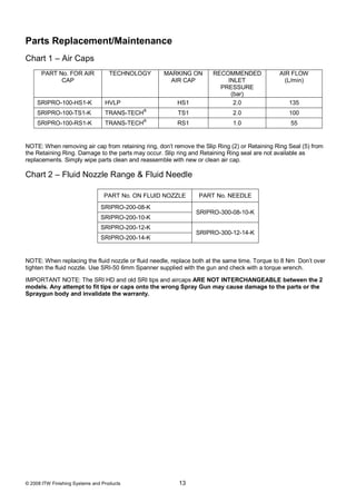
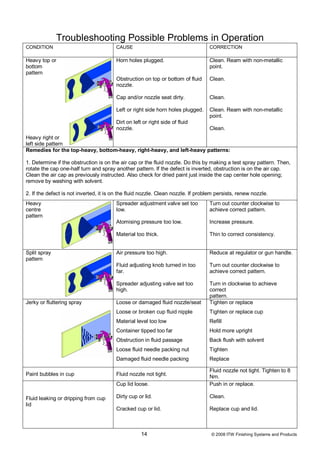
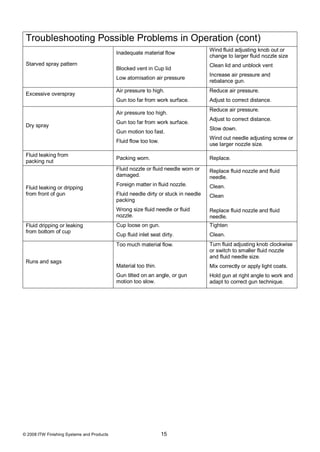
EN
                                  SB-E-2-851 ISS.02


       Technical Bulletin
SRI-HD range of Gravity Spray Guns for spot
         repairs and small areas.
Table of Contents
Topic                                                                   Page

EC Declaration of Conformity                                            3

Part Numbers                                                            3

Operational Description                                                 3

Kit contents                                                            4

Construction Features                                                   4

Materials of Construction                                               4

Specifications & Technical Data                                         4

Safety Precautions                                                      5

Parts List                                                              6

Exploded parts View                                                     7

Installation, Operation, Preventive Maintenance & Cleaning              8

Parts Replacement/Maintenance                                           9

    A. Servicing Air Valve                                              9

    B. Replacing Air Valve                                              10

    C. Needle Packing, Fluid Insert, Spreader Valve Assembly            11

    D. Spray Head Seal                                                  12

    E. Chart 1 – Air Caps, Chart 2 – Fluid Nozzles &
    Fluid Needles                                                       13

Troubleshooting Possible Problems in Operation                          14

Accessories                                                             16

Warranty                                                                16


                                   2                         © 2008 ITW Finishing Systems and Products
EC Declaration of Conformity
We, ITW Finishing UK, Ringwood Rd, Bournemouth, Dorset, BH11 9LH, UK, as the
manufacturer of the Spray gun model SRi-HD, declare, under our sole responsibility, that the
equipment to which this document relates is in conformity with the following standards or other
normative documents:
        BS EN 292-1 PARTS 1 & 2: 1991, BS EN 1953: 1999; and thereby conform to the
protection requirements of Council Directive 98/37/EEC relating to Machinery Safety Directive,
and;
        EN 13463-1:2001, council Directive 94/9/EC relating to Equipment and Protective
Systems intended for use in Potentially Explosive Atmospheres protection level II 2 G X.
This product also complies with the requirements of the EPA guidelines, PG6/34. Transfer
efficiency certificates are available on request.


                                              B. Holt, Vice President
                                                  1st Dec 2008

ITW Finishing Systems and Products reserve the right to modify equipment specification without prior notice.

Part Numbers
The ordering code for the SRI HD Spray gun is;

                                            e.g. SRIHD-TS1-10 where;
                  TS1      =         TS1 Aircap. Alternatives are HS1, and RS1 (round spray)
                  10       =         10 Nozzle. Alternatives are 08,12 or 14


Operational Description
This SRi HD Spray Gun is a professional quality gun designed with both high volume, low
pressure (HVLP) technology or EPA compliant, Trans-Tech® technology. HVLP Technology
reduces overspray and limits air cap pressure to 0.7 bar (10 psi). Trans-Tech® complies with
EPA by obtaining transfer efficiency above 65%.
IMPORTANT: These Sprayguns are suitable for use with both waterbased and solvent based
coating materials. These guns are not designed for use with highly corrosive and/or abrasive
materials and if used with such materials it must be expected that the need for cleaning and/or
replacement of parts will be increased. If there is any doubt regarding the suitability of a specific
material, contact your DeVilbiss Distributor or DeVilbiss direct.
NOTE: This gun is not to be used with halogenated hydrocarbon solvents or cleaning agents
such as 1,1,1,-Trichloroethane or methylene chloride. These solvents can react with the
aluminium components used in this gun and cup. The reaction can become violent and lead to
an equipment explosion.


© 2008 ITW Finishing Systems and Products                3
Kit contents (all models)
1   SRI HD Gravity Feed Spraygun                               1      Spanner (6mm hex and 10mm A/F)
1   SRI Gravity feed cup                                       1      Torx/Flat blade screwdriver
1   Cup Filter                                                 1      Small Cleaning Brush
1   Set of 4 coloured identification rings                     1      Large Cleaning Brush
1   Funnel                                                     1      Service bulletin CD


                                              Construction Features
                                                                      Fan Air Adjustment (stepless regulation for fan
1   Air Cap (nickel plated brass for long durability)       10
                                                                      to round spray)
    Air Cap Retaining Ring (allows easy rotation of air               Fluid Adjustment (stepless regulation of fluid
2                                                           11
    cap)                                                              volume)
                                                                      Interchangeable Colour ID System (4 coloured
3   Fluid Nozzle (ideal for automotive topcoat systems)     12
                                                                      rings supplied)
                                                                      Anodised, forged aluminium gun body
4   Fluid Needle (grooved stem for easy removal)            13        (ergonomic, good looking & durable, easy to
    Fluid Inlet (7/16” – 14 UNC thread) – accepts                     clean)
5                                                           14        125cc Acetal Cup (easy clean, anti-static)
    DeVilbiss SRI cup systems
6   Air Inlet (universal thread, accepts G 1/4 & 1/4 NPS)   15        Cup Lid with Drip Free Vent (avoid drips)
    Self Adjusting Needle Packing (for trouble free                   Air Valve (design offers low pull force & low
7                                                           16
    operation)                                                        pressure drop)
                                                                      Gun acceptable for waterborne and solvent
8   Trigger (ergonomic for comfort)                         17
                                                                      borne applications
9   Trigger Stud & Screw (easy replacement design)


                                             Materials of Construction
Gun Body                                                           Anodised aluminium
Air Cap,                                                           Nickel plated brass
Fluid Nozzle, Fluid Needle, Fluid Inlet, Trigger Stud              Stainless steel
Springs, Clips, Screws                                             Stainless steel
Seals, Gaskets                                                     Solvent resistant
Trigger                                                            Chrome plated steel
Air Inlet, Body Bushing, Spreader Valve Body, Air Valve Nut,
                                                                   Chrome plated brass
Air Cap Retaining Ring, Knobs
Air Valve Assembly                                                 Stainless Steel, HPDE


                                      Specifications & Technical Data
Air Supply Connection                                              Universal 1/4" BSP and 1/4" NPS male
Maximum Static Air Inlet Pressure                                  P1 = 12 bar (175 psi)
Gun Air Inlet Pressure for HVLP (HS1) and Trans-Tech®
                                                                   2.0 bar (29 psi)
(TS1, and RS1) with gun triggered.
Fluid Supply Connection                                            7/16 – 14 UNC
Service Temperature                                                0 to 40°C (32 to 104°F)
Gun Weight (gun only)                                              425 g
           (with cup)                                              485 g


                                                    4                              © 2008 ITW Finishing Systems and Products
SAFETY WARNINGS
                                            Fire and explosion

          Solvents and coating materials can be highly flammable or combustible when sprayed.
          ALWAYS refer to the coating material supplier’s instructions and COSHH sheets before
          using this equipment.
          Users must comply with all local and national codes of practice and insurance company
          requirements governing ventilation, fire precautions, operation and house-keeping of
          working areas.
          This equipment, as supplied, is NOT suitable for use with Halogenated Hydrocarbons.
          Static electricity can be generated by fluid and/or air passing through hoses, by the
          spraying process and by cleaning non-conductive parts with cloths. To prevent ignition
          sources from static discharges, earth continuity must be maintained to the spray gun
          and other metallic equipment used. It is essential to use conductive air and/or fluid
          hoses.
                                      Personal Protective Equipment
          Toxic vapours – When sprayed, certain materials may be poisonous, create irritation or
          be otherwise harmful to health. Always read all labels, safety data sheets and follow any
          recommendations for the material before spraying. If in doubt, contact your material
          supplier.
          The use of respiratory protective equipment is recommended at all times. The type of
          equipment must be compatible with the material being sprayed.

          Always wear eye protection when spraying or cleaning the spray gun.

          Gloves must be worn when spraying or cleaning the equipment.

Training – Personnel should be given adequate training in the safe use of spraying equipment.
                                             Misuse
Never aim a spray gun at any part of the body.
Never exceed the maximum recommended safe working pressure for the equipment.
The fitting of non-recommended or non-original spares may create hazards.
Before cleaning or maintenance, all pressure must be isolated and relieved from the equipment.
The product should be cleaned using a gun-washing machine, and should be removed and dried
immediately after cleaning is completed. Prolonged exposure to cleaning solutions can cause
damage to the product.
                                          Noise Levels
          The A-weighted sound level of spray guns may exceed 85 dB (A) depending on the set-
          up being used. Details of actual noise levels are available on request. It is
          recommended that ear protection is worn at all times when spraying.
                                            Operating
Spray equipment using high pressures may be subject to recoil forces. Under certain
circumstances, such forces could result in repetitive strain injury to the operator.


© 2008 ITW Finishing Systems and Products         5
PARTS LIST

REF.                                                       REF.                                                        QT
          DESCRIPTION             PART NO.         QTY                      DESCRIPTION               PART NO.
NO.                                                        NO.                                                         Y

 1     Air Cap Retaining Ring            -             1    32     Air Valve Poppet                        -            1

 2     Slip Ring                         -             1    33     Air Valve Spring                        -            1

 3     Air Cap                           -             1    34     Air Valve Spring Pad                    -            1

 5     Retaining Ring Seal               -             1    35     Air Valve Seal                   SN-34-K5            1

 6     Aircap & Ring            See chart 1 p13        1    36     Air Valve Assembly               SN-402-K            1
                                                                   Trigger Stud Screw (T20
 8     Fluid Nozzle             See chart 2 p13        1    *37                                            -            1
                                                                   TORX)
 9     Separator                SRIPRO-2-K5            1    38     Trigger                                 -            1

*12    Body Bushing Seal                 -             1    *39    Trigger Stud                            -            1

 13    Body Bushing                      -             1    40     Trigger, Stud & Screw Kit        SN-42-K             1

 14    Body Bushing & Seal      SN-6-K                 1    41     Stud and Screw kit               SN-405-K5           1

 15    Fluid Needle             See chart 2 p13        1    42     Air Inlet                        SN-40-K             1
                                                                   Colour ID Ring Kit (4
*16    Needle Spring                     -             1    43                                      SN-26-K4            1
                                                                   Colours)
*17    Needle Spring Pad                 -             1    44     Airflow Valve                    PRO-404-K           1

 18    Fluid Adjusting Knob              -             1    45     Circlip                                 -            1
       Fluid Adjusting Knob,
 19                             PRO-3-K                1    49     Spanner kit of 2                 SRI-50-K2           1
       Spring & Pad Kit
                                         -
*20    Retaining Clip                                  1    50     Funnel kit of 12                 SRI-51-K12          1
                                         -
 21    Spreader Valve Body                             1    51     Gravity Cup Kit                  SRI-510             1

*22    Spreader Valve Seal               -             2    52     Drip Check Lid (kit of 5)        GFC-2-K5            1
       Spreader Valve                    -
 23                                                    1    53     Gravity Cup Lid (kit of 2)       SRI-414-K2          1
       Adjusting Knob
                                         -
*24    Valve Pin                                       1    54     Gravity Cup                             -            1
       Spreader Valve
 25                             SRIPRO-401-K           1    55     Filter                           SRI-42-K5           1
       Assembly
*26    Needle Packing                    -             1    56     Air valve Service Tool                  -            1

*27    Packing Spring                    -             1    57     Torx Key                         SPN-8-K2            1

 28    Packing Nut                       -             1
       Packing, Spring &
 29                             SN-404-K               1                         SERVICE PARTS
       Packing Nut Kit
                                                           Spray Gun repair kit (includes
 30    Air Valve Body                    -                                                               PRO-415-1
                                                           items marked *)
                                                           Seal and Pin Kit, kit of 5 (items
 31    Air Valve Cage                    -             1                                                 GTI-428-K5
                                                           20, 22 and 24)
                                                                            For accessories, see page 13


                                                   6                            © 2008 ITW Finishing Systems and Products
© 2008 ITW Finishing Systems and Products   7
INSTALLATION                                                    15. Always turn off air supply and relieve pressure
For maximum transfer efficiency, do not use more                    when gun is not in use.
pressure than is necessary to atomise the material
being applied. NOTE: when using the HS1, HVLP                   PREVENTIVE MAINTENANCE &
setup do not exceed 2 bar inlet pressure.                       CLEANING
                                                                To clean air cap and fluid nozzle, brush exterior with
1.    Connect the gun to a clean, moisture and oil free         a stiff bristle brush. If necessary to clean cap holes,
      air supply using a conductive hose.                       use a broom straw or toothpick if possible. If a wire or
                                                                hard instrument is used, extreme care must be used
                          NOTE                                  to prevent scratching or burring of the holes which
      Install an air gauge at the gun handle. When gun          will cause a distorted spray pattern.
      is triggered on, adjust regulated pressure to 2.0
      bar. Do not use more pressure than is necessary           To clean fluid passages, remove excess material
      to atomise the material being applied. Excess             from cup, then flush with gun wash solution. Wipe the
      pressure will create additional overspray and             gun exterior with a dampened cloth. Never
      reduce transfer efficiency.                               completely immerse in any solvent or cleaning
                                                                solutions as this is detrimental to the lubricants and
                           NOTE                                 life of the spray gun.
      If an air adjusting valve is used at the gun inlet,                                 NOTE
      use DGI-501-bar Digital Gauge. Some                       When replacing the fluid nozzle or fluid needle,
      competitive adjusting valves have significant             replace both at the same time. Using worn parts can
      pressure drop that can adversely affect spray             cause fluid leakage. See page 13, Chart 2. Also,
      performance. The DGI Digital Gauge has                    replace the needle packing at this time. Torque the
      minimal pressure drop, which is important for             fluid nozzle to 8 Nm. Do not over tighten.
      HVLP spraying.
                                                                                     CAUTION
2.    Attach the gravity feed cup to the material inlet.
                                                                To prevent damage to fluid nozzle (8) or fluid
                                                                needle (15), be sure to either 1) pull the trigger
                          NOTE
                                                                and hold while tightening or loosening the fluid
      Before using the gun, flush it with solvent to
                                                                nozzle, or 2) remove fluid adjusting knob (18) to
      ensure that the fluid passages are clean.
                                                                relieve spring pressure against needle collar.
OPERATION                                                                            CAUTION
1.    Mix coating material to manufacturer’s                    IMPORTANT– the Gravity cup is made from
      instructions.                                             special anti-static materials, but it still important
2.    If required, fit the filter (55) in the cup (54) or use   to avoid generating static charges. The Cup must
      the funnel (50) with a paper filter.                      not be cleaned or rubbed with a dry cloth or
3.    Fill the cup to no more than 5 mm from the top of         paper. It is possible to generate a static charge
      the cup. DO NOT OVERFILL.                                 by rubbing which, if discharged to an earthed
4.    Attach Cup Lid.                                           object could create an incendive spark and cause
5.    Turn fluid adjusting knob (18) clockwise to               solvent vapours to ignite. Only use a dampened
      prevent fluid needle movement.                            cloth or antistatic wipes if manual cleaning is
6.    Turn spreader valve adjusting knob (23) counter           required within a hazardous area.
      clockwise to fully open.
7.    Adjust inlet air pressure to 2.0 bar.
8.    Turn fluid adjusting knob counter clockwise until
      first thread shows.
9.    Test spray. If the finish is too dry, reduce airflow
      by reducing air inlet pressure.
10.   If finish is too wet, reduce fluid flow by turning
      fluid adjusting knob (18) clockwise. If atomisation
      is too coarse, increase inlet air pressure. If too
      fine, reduce inlet pressure.
11.   The pattern size can be reduced by turning
      spreader valve knob (23) clockwise.
12.   Hold gun perpendicular to surface being
      sprayed. Arcing or tilting may result in uneven
      coating.
13.   The recommended spray distance is 75-150
      mm.
14.   Spray edges first. Overlap each stroke a
      minimum of 75%. Move gun at a constant speed.
                                                          8                       © 2008 ITW Finishing Systems and Products
Parts Replacement/Maintenance

AIR VALVE INSTRUCTIONS

Servicing Air Valve
Reasons to service air valve:

    A) Air valve not functioning correctly (may need
       cleaning).
    B) Routine maintenance.

    C) Air leaks (advise replacement, see p10)

1. Remove trigger using the tool supplied (SPN-8) or TORX
   T20 key. (See fig 1 & 2)
2. Unscrew air valve using SN-28 (14 mm) spanner. (See
   fig 3)
3. Remove air valve by gripping stem. (See fig 4)
4. Remove spring with spring pad. (See fig 5)
5. DO NOT REMOVE REAR SEAL (35) FROM GUN
   BODY. (See fig 6)
6. DO NOT REMOVE PLASTIC CAGE FROM AIR VALVE
   BODY AS THIS MAY DAMAGE THE CAGE. (See fig 7)
7. CLEAN
    a. Remove all paint build up. (See fig 8)
    b. The 4 poppet holes must be clear. (See fig 9)
    c. Stem must be free to float in poppet. (See fig 10)
    d. Stem must slide through cage bore with slight
       resistance (due to seal).
    e. Rear seal must look clean and in position in the
       bore. (See fig 6)
    f.   If any of the above cannot be rectified, replace the
         air valve (See Replacing Air Valve p10).
8. Replace spring ensuring the end with the plastic bearing
   pad goes in first. (See fig 5)
9. Insert air valve assembly into gun and carefully feed over
   the spring and through the rear seal. (See fig 11)
10. Tighten air valve assembly using fingers first, and then
    tighten with SN-28 (14mm) Spanner. (See figs 12 & 3)
11. Replace trigger. (See figs 2 & 1)
12. If there is an air leak through the gun, the air valve may
    need replacing (See Replacing Air Valve).


© 2008 ITW Finishing Systems and Products                   9
Replacing Air Valve

     Reasons to replace air valve:
         A) Air leak through the gun.
         B) Air valve not operating correctly.

     1. Remove trigger using SPN-8 or TORX (T20) key
        provided in the kit. (See figs 13 & 14)
     2. Unscrew air valve using SN-28 (14 mm) Spanner. (See
        fig 15)
     3. Remove air valve by gripping the stem. (See fig 16)
     4. Remove spring with spring pad. (See fig 17)
     5. Hook out rear seal using Service Tool (56). (See figs 18
        & 19)
     6. Clean air valve bores in gun body with the brush
        supplied in the kit.
     7. Place new rear seal onto Service tool (56); grooves must
        fit in service tool form. (See fig 20)
     8. Push rear seal firmly into hole up to shoulder, using
        Service tool. (See figs 21 & 22)
     9. Insert new spring, ensuring the end with the plastic
        bearing pad goes in first. (See fig 17)
     10. Insert air valve assembly into gun and carefully feed
         over the spring and through the rear seal. (See fig 23)
     11. Tighten air valve assembly using fingers first, then
         tighten with SN-28 (14 mm) Spanner. (See figs 24 & 15)
     12. Replace trigger. (See figs 14 & 13)


10                            © 2008 ITW Finishing Systems and Products
Parts Replacement/Maintenance

NEEDLE PACKING
REPLACEMENT INSTRUCTIONS
13. Remove trigger using SPN-8 (57) or TORX (T20) driver.
    (See figs 25 & 26)
14. Remove fluid adjusting knob and needle spring with
    spring pad from gun. (See figs 27 & 28)
15. Remove fluid needle from gun body. (See fig 29)
16. Loosen and remove packing nut using SPN-8 (57) Key or
    a straight blade screwdriver. (See figs 30 & 31)
17. Discard old packing and packing spring if replacing.
    Clean packing if reusing. Also clean packing spring and
    nut. (See fig 32).
18. Re-assemble the packing, (See fig 32). Assemble into
    gunbody by hand (see fig 33) and then tighten. (See figs
    30 and 31)
19. Insert fluid needle all the way into gun body seating in
    fluid nozzle (See fig 34).
20. Insert needle spring, spring pad, and fluid adjusting knob.
    (See figs 28 & 27). Reinstall trigger. (See figs 25 & 26).
21. Trigger gun fully and screw in fluid adjusting knob until it
    stops. Back it off 1/2 turn and gun will have full needle
    travel.
22. Trigger gun several times to verify correct operation.


SPREADER VALVE ASSEMBLY
REPLACEMENT/MAINTENANCE
The spreader valve assembly can be replaced if damaged.
Remove using SN-28 (14 mm) Spanner (See figs 35 & 36).
The internal seal can be replaced and is included in the PRO
Gun Rebuild Kit.


© 2008 ITW Finishing Systems and Products                      11
Parts Replacement/
     Maintenance

     SEPARATOR SEAL
     REPLACEMENT

     1. Remove air cap and retaining ring. (See fig 37)
     2. Remove fluid adjusting knob, spring, and spring pad.
        (See figs 38 & 39)
     3. Remove fluid needle from gun body. (See fig 40)
     4. Remove fluid nozzle using SRI-50 (8 mm) Spanner.
        (See figs 41, & 42)
     5. Remove Separator. (See fig 43).
     6. Clean front of gun if required, using a soft brush, as
        well as the fluid nozzle, air cap, and retaining ring.
     7. Place a new Separator Seal into the front of the gun,
        making sure the flat side of the seal is aligned with
        the flat in the gun. (See fig 44).
     8. Fit Fluid Nozzle, Air Cap, and Retaining Ring.
        Torque the Fluid Nozzle to 8 Nm Don’t over torque
        the Fluid Nozzle. (See figs 45, 46, and 37)
     9. Insert Fluid Needle all the way into the Gun Body,
        seating in the Fluid Nozzle. (See fig 47)
     10. Reassemble Needle Spring, Spring Pad, and Fluid
         adjusting Knob. (See fig 47)
     11. Trigger gun fully and screw in Fluid Adjusting Knob
         until it stops. Back it off 3 turns and gun will have full
         needle travel.
     12. Trigger gun several times to verify correct operation
         (see fig 48).


12                         © 2008 ITW Finishing Systems and Products
Parts Replacement/Maintenance
Chart 1 – Air Caps
      PART No. FOR AIR              TECHNOLOGY     MARKING ON        RECOMMENDED              AIR FLOW
            CAP                                      AIR CAP             INLET                  (L/min)
                                                                       PRESSURE
                                                                          (bar)
     SRIPRO-100-HS1-K             HVLP                  HS1                2.0                    135
                                            ®
     SRIPRO-100-TS1-K             TRANS-TECH            TS1                  2.0                  100
                                            ®
     SRIPRO-100-RS1-K             TRANS-TECH            RS1                  1.0                  55


NOTE: When removing air cap from retaining ring, don’t remove the Slip Ring (2) or Retaining Ring Seal (5) from
the Retaining Ring. Damage to the parts may occur. Slip ring and Retaining Ring seal are not available as
replacements. Simply wipe parts clean and reassemble with new or clean air cap.

Chart 2 – Fluid Nozzle Range & Fluid Needle

                                 PART No. ON FLUID NOZZLE       PART No. NEEDLE
                                SRIPRO-200-08-K
                                                               SRIPRO-300-08-10-K
                                SRIPRO-200-10-K
                                SRIPRO-200-12-K
                                                               SRIPRO-300-12-14-K
                                SRIPRO-200-14-K


NOTE: When replacing the fluid nozzle or fluid needle, replace both at the same time. Torque to 8 Nm Don’t over
tighten the fluid nozzle. Use SRI-50 6mm Spanner supplied with the gun and check with a torque wrench.

IMPORTANT NOTE: The SRI HD and old SRI tips and aircaps ARE NOT INTERCHANGEABLE between the 2
models. Any attempt to fit tips or caps onto the wrong Spray Gun may cause damage to the parts or the
Spraygun body and invalidate the warranty.


© 2008 ITW Finishing Systems and Products                13
Troubleshooting Possible Problems in Operation
CONDITION                               CAUSE                                     CORRECTION

Heavy top or                            Horn holes plugged.                       Clean. Ream with non-metallic
bottom                                                                            point.
pattern
                                        Obstruction on top or bottom of fluid     Clean.
                                        nozzle.

                                        Cap and/or nozzle seat dirty.             Clean.

                                        Left or right side horn holes plugged.    Clean. Ream with non-metallic
                                                                                  point.
                                        Dirt on left or right side of fluid
                                        nozzle.                                   Clean.
Heavy right or
left side pattern
Remedies for the top-heavy, bottom-heavy, right-heavy, and left-heavy patterns:

1. Determine if the obstruction is on the air cap or the fluid nozzle. Do this by making a test spray pattern. Then,
rotate the cap one-half turn and spray another pattern. If the defect is inverted, obstruction is on the air cap.
Clean the air cap as previously instructed. Also check for dried paint just inside the cap center hole opening;
remove by washing with solvent.

2. If the defect is not inverted, it is on the fluid nozzle. Clean nozzle. If problem persists, renew nozzle.
Heavy                                   Spreader adjustment valve set too         Turn out counter clockwise to
centre                                  low.                                      achieve correct pattern.
pattern
                                        Atomising pressure too low.               Increase pressure.

                                        Material too thick.                       Thin to correct consistency.


Split spray                             Air pressure too high.                    Reduce at regulator or gun handle.
pattern
                                        Fluid adjusting knob turned in too        Turn out counter clockwise to
                                        far.                                      achieve correct pattern.

                                        Spreader adjusting valve set too          Turn in clockwise to achieve
                                        high.                                     correct
                                                                                  pattern.
Jerky or fluttering spray               Loose or damaged fluid nozzle/seat        Tighten or replace
                                        Loose or broken cup fluid nipple          Tighten or replace cup
                                        Material level too low                    Refill
                                        Container tipped too far                  Hold more upright
                                        Obstruction in fluid passage              Back flush with solvent
                                        Loose fluid needle packing nut            Tighten
                                        Damaged fluid needle packing              Replace

                                                                                  Fluid nozzle not tight. Tighten to 8
Paint bubbles in cup                    Fluid nozzle not tight.                   Nm.
                                        Cup lid loose.                            Push in or replace.

Fluid leaking or dripping from cup      Dirty cup or lid.                         Clean.
lid
                                        Cracked cup or lid.                       Replace cup and lid.


                                                    14                             © 2008 ITW Finishing Systems and Products
Troubleshooting Possible Problems in Operation (cont)
                                                                                    Wind fluid adjusting knob out or
                                            Inadequate material flow
                                                                                    change to larger fluid nozzle size
 Starved spray pattern                                                              Clean lid and unblock vent
                                            Blocked vent in Cup lid
                                                                                    Increase air pressure and
                                            Low atomisation air pressure
                                                                                    rebalance gun.
                                            Air pressure to high.                   Reduce air pressure.
 Excessive overspray
                                            Gun too far from work surface.          Adjust to correct distance.
                                                                                    Reduce air pressure.
                                            Air pressure too high.
                                                                                    Adjust to correct distance.
                                            Gun too far from work surface.
 Dry spray
                                                                                    Slow down.
                                            Gun motion too fast.
                                                                                    Wind out needle adjusting screw or
                                            Fluid flow too low.
                                                                                    use larger nozzle size.
 Fluid leaking from
                                            Packing worn.                           Replace.
 packing nut
                                            Fluid nozzle or fluid needle worn or    Replace fluid nozzle and fluid
                                            damaged.                                needle.
                                            Foreign matter in fluid nozzle.         Clean.
 Fluid leaking or dripping
 from front of gun                          Fluid needle dirty or stuck in needle   Clean
                                            packing
                                            Wrong size fluid needle or fluid        Replace fluid nozzle and fluid
                                            nozzle.                                 needle.
 Fluid dripping or leaking                  Cup loose on gun.                       Tighten
 from bottom of cup
                                            Cup fluid inlet seat dirty.             Clean.
                                            Too much material flow.                 Turn fluid adjusting knob clockwise
                                                                                    or switch to smaller fluid nozzle
                                                                                    and fluid needle size.
 Runs and sags
                                            Material too thin.                      Mix correctly or apply light coats.
                                            Gun tilted on an angle, or gun          Hold gun at right angle to work and
                                            motion too slow.                        adapt to correct gun technique.


© 2008 ITW Finishing Systems and Products                         15
ACCESSORIES


DGi Digital
                      DGI-501-BAR                               Gun Stand          GFV-50-F
Pressure Gauge


                                                                                   600 cc Mixing
Spanner               SN-28-K                                   MC-1-K50           Cups pack of 50

                                                                10m x 8mm
                                                                bore rubber air    H-6065-B (BSP)
Torx driver           SPN-8-K2
                                                                hose with ¼        H-6065-N (NPS)
                                                                fittings

                                                                Pack of four
MPV Swivel            MPV-60-K3                                                    MPV-463
                                                                QD fittings


                                                                Disposable
Cleaning Brush        4900-5-1-K3                                                  SRI-479-K12
                                                                Cup, Kit of 12


WARRANTY
This product is covered by ITW Finishing Systems and Products Limited one year warranty.


ITW Finishing Systems and Products                       ITW Oberflächentechnik GmbH & Co. KG
Ringwood Road,                                           Justus-von-Liebig-Straße 31
Bournemouth,                                             63128 Dietzenbach
BH11 9LH, UK                                             Tel (060 74) 403-1
Tel. No. (01202) 571111                                  Telefax: (060 74) 403300
Telefax No. (01202) 581940,                              Website address http://www.devilbisseu.com
Website address http://www.devilbisseu.com

ITW Automotive Finishing UK                              ITW Surfaces Et Finitions
Anchorbrook Industrial Estate                            163-171 avenue des Auréats B.P. 1453
Lockside                                                 26014 VALENCE CEDEX FRANCE
Aldridge,                                                Tél. (33) 475-75-27-00
Walsall, UK.                                             Télex 345 719F DVILBIS
Tel. No. (01922) 423700                                  Téléfax: (33) 475-75-27-99
Telefax No. (01922) 423705,                              http://www.devilbisseu.com
Website address http://www.itweuropeanfinishing.com

ITW Finishing Systems and Products is a Division of ITW Ltd. Reg. Office: Admiral House, St Leonard’s Road, Windsor,
Berkshire,SL4 3BL,UK. Registered in England: No 559693 Vat No 619 5461 24


                                                    16                              © 2008 ITW Finishing Systems and Products

SRi Hd

  • 1.
    EN SB-E-2-851 ISS.02 Technical Bulletin SRI-HD range of Gravity Spray Guns for spot repairs and small areas.
  • 2.
    Table of Contents Topic Page EC Declaration of Conformity 3 Part Numbers 3 Operational Description 3 Kit contents 4 Construction Features 4 Materials of Construction 4 Specifications & Technical Data 4 Safety Precautions 5 Parts List 6 Exploded parts View 7 Installation, Operation, Preventive Maintenance & Cleaning 8 Parts Replacement/Maintenance 9 A. Servicing Air Valve 9 B. Replacing Air Valve 10 C. Needle Packing, Fluid Insert, Spreader Valve Assembly 11 D. Spray Head Seal 12 E. Chart 1 – Air Caps, Chart 2 – Fluid Nozzles & Fluid Needles 13 Troubleshooting Possible Problems in Operation 14 Accessories 16 Warranty 16 2 © 2008 ITW Finishing Systems and Products
  • 3.
    EC Declaration ofConformity We, ITW Finishing UK, Ringwood Rd, Bournemouth, Dorset, BH11 9LH, UK, as the manufacturer of the Spray gun model SRi-HD, declare, under our sole responsibility, that the equipment to which this document relates is in conformity with the following standards or other normative documents: BS EN 292-1 PARTS 1 & 2: 1991, BS EN 1953: 1999; and thereby conform to the protection requirements of Council Directive 98/37/EEC relating to Machinery Safety Directive, and; EN 13463-1:2001, council Directive 94/9/EC relating to Equipment and Protective Systems intended for use in Potentially Explosive Atmospheres protection level II 2 G X. This product also complies with the requirements of the EPA guidelines, PG6/34. Transfer efficiency certificates are available on request. B. Holt, Vice President 1st Dec 2008 ITW Finishing Systems and Products reserve the right to modify equipment specification without prior notice. Part Numbers The ordering code for the SRI HD Spray gun is; e.g. SRIHD-TS1-10 where; TS1 = TS1 Aircap. Alternatives are HS1, and RS1 (round spray) 10 = 10 Nozzle. Alternatives are 08,12 or 14 Operational Description This SRi HD Spray Gun is a professional quality gun designed with both high volume, low pressure (HVLP) technology or EPA compliant, Trans-Tech® technology. HVLP Technology reduces overspray and limits air cap pressure to 0.7 bar (10 psi). Trans-Tech® complies with EPA by obtaining transfer efficiency above 65%. IMPORTANT: These Sprayguns are suitable for use with both waterbased and solvent based coating materials. These guns are not designed for use with highly corrosive and/or abrasive materials and if used with such materials it must be expected that the need for cleaning and/or replacement of parts will be increased. If there is any doubt regarding the suitability of a specific material, contact your DeVilbiss Distributor or DeVilbiss direct. NOTE: This gun is not to be used with halogenated hydrocarbon solvents or cleaning agents such as 1,1,1,-Trichloroethane or methylene chloride. These solvents can react with the aluminium components used in this gun and cup. The reaction can become violent and lead to an equipment explosion. © 2008 ITW Finishing Systems and Products 3
  • 4.
    Kit contents (allmodels) 1 SRI HD Gravity Feed Spraygun 1 Spanner (6mm hex and 10mm A/F) 1 SRI Gravity feed cup 1 Torx/Flat blade screwdriver 1 Cup Filter 1 Small Cleaning Brush 1 Set of 4 coloured identification rings 1 Large Cleaning Brush 1 Funnel 1 Service bulletin CD Construction Features Fan Air Adjustment (stepless regulation for fan 1 Air Cap (nickel plated brass for long durability) 10 to round spray) Air Cap Retaining Ring (allows easy rotation of air Fluid Adjustment (stepless regulation of fluid 2 11 cap) volume) Interchangeable Colour ID System (4 coloured 3 Fluid Nozzle (ideal for automotive topcoat systems) 12 rings supplied) Anodised, forged aluminium gun body 4 Fluid Needle (grooved stem for easy removal) 13 (ergonomic, good looking & durable, easy to Fluid Inlet (7/16” – 14 UNC thread) – accepts clean) 5 14 125cc Acetal Cup (easy clean, anti-static) DeVilbiss SRI cup systems 6 Air Inlet (universal thread, accepts G 1/4 & 1/4 NPS) 15 Cup Lid with Drip Free Vent (avoid drips) Self Adjusting Needle Packing (for trouble free Air Valve (design offers low pull force & low 7 16 operation) pressure drop) Gun acceptable for waterborne and solvent 8 Trigger (ergonomic for comfort) 17 borne applications 9 Trigger Stud & Screw (easy replacement design) Materials of Construction Gun Body Anodised aluminium Air Cap, Nickel plated brass Fluid Nozzle, Fluid Needle, Fluid Inlet, Trigger Stud Stainless steel Springs, Clips, Screws Stainless steel Seals, Gaskets Solvent resistant Trigger Chrome plated steel Air Inlet, Body Bushing, Spreader Valve Body, Air Valve Nut, Chrome plated brass Air Cap Retaining Ring, Knobs Air Valve Assembly Stainless Steel, HPDE Specifications & Technical Data Air Supply Connection Universal 1/4" BSP and 1/4" NPS male Maximum Static Air Inlet Pressure P1 = 12 bar (175 psi) Gun Air Inlet Pressure for HVLP (HS1) and Trans-Tech® 2.0 bar (29 psi) (TS1, and RS1) with gun triggered. Fluid Supply Connection 7/16 – 14 UNC Service Temperature 0 to 40°C (32 to 104°F) Gun Weight (gun only) 425 g (with cup) 485 g 4 © 2008 ITW Finishing Systems and Products
  • 5.
    SAFETY WARNINGS Fire and explosion Solvents and coating materials can be highly flammable or combustible when sprayed. ALWAYS refer to the coating material supplier’s instructions and COSHH sheets before using this equipment. Users must comply with all local and national codes of practice and insurance company requirements governing ventilation, fire precautions, operation and house-keeping of working areas. This equipment, as supplied, is NOT suitable for use with Halogenated Hydrocarbons. Static electricity can be generated by fluid and/or air passing through hoses, by the spraying process and by cleaning non-conductive parts with cloths. To prevent ignition sources from static discharges, earth continuity must be maintained to the spray gun and other metallic equipment used. It is essential to use conductive air and/or fluid hoses. Personal Protective Equipment Toxic vapours – When sprayed, certain materials may be poisonous, create irritation or be otherwise harmful to health. Always read all labels, safety data sheets and follow any recommendations for the material before spraying. If in doubt, contact your material supplier. The use of respiratory protective equipment is recommended at all times. The type of equipment must be compatible with the material being sprayed. Always wear eye protection when spraying or cleaning the spray gun. Gloves must be worn when spraying or cleaning the equipment. Training – Personnel should be given adequate training in the safe use of spraying equipment. Misuse Never aim a spray gun at any part of the body. Never exceed the maximum recommended safe working pressure for the equipment. The fitting of non-recommended or non-original spares may create hazards. Before cleaning or maintenance, all pressure must be isolated and relieved from the equipment. The product should be cleaned using a gun-washing machine, and should be removed and dried immediately after cleaning is completed. Prolonged exposure to cleaning solutions can cause damage to the product. Noise Levels The A-weighted sound level of spray guns may exceed 85 dB (A) depending on the set- up being used. Details of actual noise levels are available on request. It is recommended that ear protection is worn at all times when spraying. Operating Spray equipment using high pressures may be subject to recoil forces. Under certain circumstances, such forces could result in repetitive strain injury to the operator. © 2008 ITW Finishing Systems and Products 5
  • 6.
    PARTS LIST REF. REF. QT DESCRIPTION PART NO. QTY DESCRIPTION PART NO. NO. NO. Y 1 Air Cap Retaining Ring - 1 32 Air Valve Poppet - 1 2 Slip Ring - 1 33 Air Valve Spring - 1 3 Air Cap - 1 34 Air Valve Spring Pad - 1 5 Retaining Ring Seal - 1 35 Air Valve Seal SN-34-K5 1 6 Aircap & Ring See chart 1 p13 1 36 Air Valve Assembly SN-402-K 1 Trigger Stud Screw (T20 8 Fluid Nozzle See chart 2 p13 1 *37 - 1 TORX) 9 Separator SRIPRO-2-K5 1 38 Trigger - 1 *12 Body Bushing Seal - 1 *39 Trigger Stud - 1 13 Body Bushing - 1 40 Trigger, Stud & Screw Kit SN-42-K 1 14 Body Bushing & Seal SN-6-K 1 41 Stud and Screw kit SN-405-K5 1 15 Fluid Needle See chart 2 p13 1 42 Air Inlet SN-40-K 1 Colour ID Ring Kit (4 *16 Needle Spring - 1 43 SN-26-K4 1 Colours) *17 Needle Spring Pad - 1 44 Airflow Valve PRO-404-K 1 18 Fluid Adjusting Knob - 1 45 Circlip - 1 Fluid Adjusting Knob, 19 PRO-3-K 1 49 Spanner kit of 2 SRI-50-K2 1 Spring & Pad Kit - *20 Retaining Clip 1 50 Funnel kit of 12 SRI-51-K12 1 - 21 Spreader Valve Body 1 51 Gravity Cup Kit SRI-510 1 *22 Spreader Valve Seal - 2 52 Drip Check Lid (kit of 5) GFC-2-K5 1 Spreader Valve - 23 1 53 Gravity Cup Lid (kit of 2) SRI-414-K2 1 Adjusting Knob - *24 Valve Pin 1 54 Gravity Cup - 1 Spreader Valve 25 SRIPRO-401-K 1 55 Filter SRI-42-K5 1 Assembly *26 Needle Packing - 1 56 Air valve Service Tool - 1 *27 Packing Spring - 1 57 Torx Key SPN-8-K2 1 28 Packing Nut - 1 Packing, Spring & 29 SN-404-K 1 SERVICE PARTS Packing Nut Kit Spray Gun repair kit (includes 30 Air Valve Body - PRO-415-1 items marked *) Seal and Pin Kit, kit of 5 (items 31 Air Valve Cage - 1 GTI-428-K5 20, 22 and 24) For accessories, see page 13 6 © 2008 ITW Finishing Systems and Products
  • 7.
    © 2008 ITWFinishing Systems and Products 7
  • 8.
    INSTALLATION 15. Always turn off air supply and relieve pressure For maximum transfer efficiency, do not use more when gun is not in use. pressure than is necessary to atomise the material being applied. NOTE: when using the HS1, HVLP PREVENTIVE MAINTENANCE & setup do not exceed 2 bar inlet pressure. CLEANING To clean air cap and fluid nozzle, brush exterior with 1. Connect the gun to a clean, moisture and oil free a stiff bristle brush. If necessary to clean cap holes, air supply using a conductive hose. use a broom straw or toothpick if possible. If a wire or hard instrument is used, extreme care must be used NOTE to prevent scratching or burring of the holes which Install an air gauge at the gun handle. When gun will cause a distorted spray pattern. is triggered on, adjust regulated pressure to 2.0 bar. Do not use more pressure than is necessary To clean fluid passages, remove excess material to atomise the material being applied. Excess from cup, then flush with gun wash solution. Wipe the pressure will create additional overspray and gun exterior with a dampened cloth. Never reduce transfer efficiency. completely immerse in any solvent or cleaning solutions as this is detrimental to the lubricants and NOTE life of the spray gun. If an air adjusting valve is used at the gun inlet, NOTE use DGI-501-bar Digital Gauge. Some When replacing the fluid nozzle or fluid needle, competitive adjusting valves have significant replace both at the same time. Using worn parts can pressure drop that can adversely affect spray cause fluid leakage. See page 13, Chart 2. Also, performance. The DGI Digital Gauge has replace the needle packing at this time. Torque the minimal pressure drop, which is important for fluid nozzle to 8 Nm. Do not over tighten. HVLP spraying. CAUTION 2. Attach the gravity feed cup to the material inlet. To prevent damage to fluid nozzle (8) or fluid needle (15), be sure to either 1) pull the trigger NOTE and hold while tightening or loosening the fluid Before using the gun, flush it with solvent to nozzle, or 2) remove fluid adjusting knob (18) to ensure that the fluid passages are clean. relieve spring pressure against needle collar. OPERATION CAUTION 1. Mix coating material to manufacturer’s IMPORTANT– the Gravity cup is made from instructions. special anti-static materials, but it still important 2. If required, fit the filter (55) in the cup (54) or use to avoid generating static charges. The Cup must the funnel (50) with a paper filter. not be cleaned or rubbed with a dry cloth or 3. Fill the cup to no more than 5 mm from the top of paper. It is possible to generate a static charge the cup. DO NOT OVERFILL. by rubbing which, if discharged to an earthed 4. Attach Cup Lid. object could create an incendive spark and cause 5. Turn fluid adjusting knob (18) clockwise to solvent vapours to ignite. Only use a dampened prevent fluid needle movement. cloth or antistatic wipes if manual cleaning is 6. Turn spreader valve adjusting knob (23) counter required within a hazardous area. clockwise to fully open. 7. Adjust inlet air pressure to 2.0 bar. 8. Turn fluid adjusting knob counter clockwise until first thread shows. 9. Test spray. If the finish is too dry, reduce airflow by reducing air inlet pressure. 10. If finish is too wet, reduce fluid flow by turning fluid adjusting knob (18) clockwise. If atomisation is too coarse, increase inlet air pressure. If too fine, reduce inlet pressure. 11. The pattern size can be reduced by turning spreader valve knob (23) clockwise. 12. Hold gun perpendicular to surface being sprayed. Arcing or tilting may result in uneven coating. 13. The recommended spray distance is 75-150 mm. 14. Spray edges first. Overlap each stroke a minimum of 75%. Move gun at a constant speed. 8 © 2008 ITW Finishing Systems and Products
  • 9.
    Parts Replacement/Maintenance AIR VALVEINSTRUCTIONS Servicing Air Valve Reasons to service air valve: A) Air valve not functioning correctly (may need cleaning). B) Routine maintenance. C) Air leaks (advise replacement, see p10) 1. Remove trigger using the tool supplied (SPN-8) or TORX T20 key. (See fig 1 & 2) 2. Unscrew air valve using SN-28 (14 mm) spanner. (See fig 3) 3. Remove air valve by gripping stem. (See fig 4) 4. Remove spring with spring pad. (See fig 5) 5. DO NOT REMOVE REAR SEAL (35) FROM GUN BODY. (See fig 6) 6. DO NOT REMOVE PLASTIC CAGE FROM AIR VALVE BODY AS THIS MAY DAMAGE THE CAGE. (See fig 7) 7. CLEAN a. Remove all paint build up. (See fig 8) b. The 4 poppet holes must be clear. (See fig 9) c. Stem must be free to float in poppet. (See fig 10) d. Stem must slide through cage bore with slight resistance (due to seal). e. Rear seal must look clean and in position in the bore. (See fig 6) f. If any of the above cannot be rectified, replace the air valve (See Replacing Air Valve p10). 8. Replace spring ensuring the end with the plastic bearing pad goes in first. (See fig 5) 9. Insert air valve assembly into gun and carefully feed over the spring and through the rear seal. (See fig 11) 10. Tighten air valve assembly using fingers first, and then tighten with SN-28 (14mm) Spanner. (See figs 12 & 3) 11. Replace trigger. (See figs 2 & 1) 12. If there is an air leak through the gun, the air valve may need replacing (See Replacing Air Valve). © 2008 ITW Finishing Systems and Products 9
  • 10.
    Replacing Air Valve Reasons to replace air valve: A) Air leak through the gun. B) Air valve not operating correctly. 1. Remove trigger using SPN-8 or TORX (T20) key provided in the kit. (See figs 13 & 14) 2. Unscrew air valve using SN-28 (14 mm) Spanner. (See fig 15) 3. Remove air valve by gripping the stem. (See fig 16) 4. Remove spring with spring pad. (See fig 17) 5. Hook out rear seal using Service Tool (56). (See figs 18 & 19) 6. Clean air valve bores in gun body with the brush supplied in the kit. 7. Place new rear seal onto Service tool (56); grooves must fit in service tool form. (See fig 20) 8. Push rear seal firmly into hole up to shoulder, using Service tool. (See figs 21 & 22) 9. Insert new spring, ensuring the end with the plastic bearing pad goes in first. (See fig 17) 10. Insert air valve assembly into gun and carefully feed over the spring and through the rear seal. (See fig 23) 11. Tighten air valve assembly using fingers first, then tighten with SN-28 (14 mm) Spanner. (See figs 24 & 15) 12. Replace trigger. (See figs 14 & 13) 10 © 2008 ITW Finishing Systems and Products
  • 11.
    Parts Replacement/Maintenance NEEDLE PACKING REPLACEMENTINSTRUCTIONS 13. Remove trigger using SPN-8 (57) or TORX (T20) driver. (See figs 25 & 26) 14. Remove fluid adjusting knob and needle spring with spring pad from gun. (See figs 27 & 28) 15. Remove fluid needle from gun body. (See fig 29) 16. Loosen and remove packing nut using SPN-8 (57) Key or a straight blade screwdriver. (See figs 30 & 31) 17. Discard old packing and packing spring if replacing. Clean packing if reusing. Also clean packing spring and nut. (See fig 32). 18. Re-assemble the packing, (See fig 32). Assemble into gunbody by hand (see fig 33) and then tighten. (See figs 30 and 31) 19. Insert fluid needle all the way into gun body seating in fluid nozzle (See fig 34). 20. Insert needle spring, spring pad, and fluid adjusting knob. (See figs 28 & 27). Reinstall trigger. (See figs 25 & 26). 21. Trigger gun fully and screw in fluid adjusting knob until it stops. Back it off 1/2 turn and gun will have full needle travel. 22. Trigger gun several times to verify correct operation. SPREADER VALVE ASSEMBLY REPLACEMENT/MAINTENANCE The spreader valve assembly can be replaced if damaged. Remove using SN-28 (14 mm) Spanner (See figs 35 & 36). The internal seal can be replaced and is included in the PRO Gun Rebuild Kit. © 2008 ITW Finishing Systems and Products 11
  • 12.
    Parts Replacement/ Maintenance SEPARATOR SEAL REPLACEMENT 1. Remove air cap and retaining ring. (See fig 37) 2. Remove fluid adjusting knob, spring, and spring pad. (See figs 38 & 39) 3. Remove fluid needle from gun body. (See fig 40) 4. Remove fluid nozzle using SRI-50 (8 mm) Spanner. (See figs 41, & 42) 5. Remove Separator. (See fig 43). 6. Clean front of gun if required, using a soft brush, as well as the fluid nozzle, air cap, and retaining ring. 7. Place a new Separator Seal into the front of the gun, making sure the flat side of the seal is aligned with the flat in the gun. (See fig 44). 8. Fit Fluid Nozzle, Air Cap, and Retaining Ring. Torque the Fluid Nozzle to 8 Nm Don’t over torque the Fluid Nozzle. (See figs 45, 46, and 37) 9. Insert Fluid Needle all the way into the Gun Body, seating in the Fluid Nozzle. (See fig 47) 10. Reassemble Needle Spring, Spring Pad, and Fluid adjusting Knob. (See fig 47) 11. Trigger gun fully and screw in Fluid Adjusting Knob until it stops. Back it off 3 turns and gun will have full needle travel. 12. Trigger gun several times to verify correct operation (see fig 48). 12 © 2008 ITW Finishing Systems and Products
  • 13.
    Parts Replacement/Maintenance Chart 1– Air Caps PART No. FOR AIR TECHNOLOGY MARKING ON RECOMMENDED AIR FLOW CAP AIR CAP INLET (L/min) PRESSURE (bar) SRIPRO-100-HS1-K HVLP HS1 2.0 135 ® SRIPRO-100-TS1-K TRANS-TECH TS1 2.0 100 ® SRIPRO-100-RS1-K TRANS-TECH RS1 1.0 55 NOTE: When removing air cap from retaining ring, don’t remove the Slip Ring (2) or Retaining Ring Seal (5) from the Retaining Ring. Damage to the parts may occur. Slip ring and Retaining Ring seal are not available as replacements. Simply wipe parts clean and reassemble with new or clean air cap. Chart 2 – Fluid Nozzle Range & Fluid Needle PART No. ON FLUID NOZZLE PART No. NEEDLE SRIPRO-200-08-K SRIPRO-300-08-10-K SRIPRO-200-10-K SRIPRO-200-12-K SRIPRO-300-12-14-K SRIPRO-200-14-K NOTE: When replacing the fluid nozzle or fluid needle, replace both at the same time. Torque to 8 Nm Don’t over tighten the fluid nozzle. Use SRI-50 6mm Spanner supplied with the gun and check with a torque wrench. IMPORTANT NOTE: The SRI HD and old SRI tips and aircaps ARE NOT INTERCHANGEABLE between the 2 models. Any attempt to fit tips or caps onto the wrong Spray Gun may cause damage to the parts or the Spraygun body and invalidate the warranty. © 2008 ITW Finishing Systems and Products 13
  • 14.
    Troubleshooting Possible Problemsin Operation CONDITION CAUSE CORRECTION Heavy top or Horn holes plugged. Clean. Ream with non-metallic bottom point. pattern Obstruction on top or bottom of fluid Clean. nozzle. Cap and/or nozzle seat dirty. Clean. Left or right side horn holes plugged. Clean. Ream with non-metallic point. Dirt on left or right side of fluid nozzle. Clean. Heavy right or left side pattern Remedies for the top-heavy, bottom-heavy, right-heavy, and left-heavy patterns: 1. Determine if the obstruction is on the air cap or the fluid nozzle. Do this by making a test spray pattern. Then, rotate the cap one-half turn and spray another pattern. If the defect is inverted, obstruction is on the air cap. Clean the air cap as previously instructed. Also check for dried paint just inside the cap center hole opening; remove by washing with solvent. 2. If the defect is not inverted, it is on the fluid nozzle. Clean nozzle. If problem persists, renew nozzle. Heavy Spreader adjustment valve set too Turn out counter clockwise to centre low. achieve correct pattern. pattern Atomising pressure too low. Increase pressure. Material too thick. Thin to correct consistency. Split spray Air pressure too high. Reduce at regulator or gun handle. pattern Fluid adjusting knob turned in too Turn out counter clockwise to far. achieve correct pattern. Spreader adjusting valve set too Turn in clockwise to achieve high. correct pattern. Jerky or fluttering spray Loose or damaged fluid nozzle/seat Tighten or replace Loose or broken cup fluid nipple Tighten or replace cup Material level too low Refill Container tipped too far Hold more upright Obstruction in fluid passage Back flush with solvent Loose fluid needle packing nut Tighten Damaged fluid needle packing Replace Fluid nozzle not tight. Tighten to 8 Paint bubbles in cup Fluid nozzle not tight. Nm. Cup lid loose. Push in or replace. Fluid leaking or dripping from cup Dirty cup or lid. Clean. lid Cracked cup or lid. Replace cup and lid. 14 © 2008 ITW Finishing Systems and Products
  • 15.
    Troubleshooting Possible Problemsin Operation (cont) Wind fluid adjusting knob out or Inadequate material flow change to larger fluid nozzle size Starved spray pattern Clean lid and unblock vent Blocked vent in Cup lid Increase air pressure and Low atomisation air pressure rebalance gun. Air pressure to high. Reduce air pressure. Excessive overspray Gun too far from work surface. Adjust to correct distance. Reduce air pressure. Air pressure too high. Adjust to correct distance. Gun too far from work surface. Dry spray Slow down. Gun motion too fast. Wind out needle adjusting screw or Fluid flow too low. use larger nozzle size. Fluid leaking from Packing worn. Replace. packing nut Fluid nozzle or fluid needle worn or Replace fluid nozzle and fluid damaged. needle. Foreign matter in fluid nozzle. Clean. Fluid leaking or dripping from front of gun Fluid needle dirty or stuck in needle Clean packing Wrong size fluid needle or fluid Replace fluid nozzle and fluid nozzle. needle. Fluid dripping or leaking Cup loose on gun. Tighten from bottom of cup Cup fluid inlet seat dirty. Clean. Too much material flow. Turn fluid adjusting knob clockwise or switch to smaller fluid nozzle and fluid needle size. Runs and sags Material too thin. Mix correctly or apply light coats. Gun tilted on an angle, or gun Hold gun at right angle to work and motion too slow. adapt to correct gun technique. © 2008 ITW Finishing Systems and Products 15
  • 16.
    ACCESSORIES DGi Digital DGI-501-BAR Gun Stand GFV-50-F Pressure Gauge 600 cc Mixing Spanner SN-28-K MC-1-K50 Cups pack of 50 10m x 8mm bore rubber air H-6065-B (BSP) Torx driver SPN-8-K2 hose with ¼ H-6065-N (NPS) fittings Pack of four MPV Swivel MPV-60-K3 MPV-463 QD fittings Disposable Cleaning Brush 4900-5-1-K3 SRI-479-K12 Cup, Kit of 12 WARRANTY This product is covered by ITW Finishing Systems and Products Limited one year warranty. ITW Finishing Systems and Products ITW Oberflächentechnik GmbH & Co. KG Ringwood Road, Justus-von-Liebig-Straße 31 Bournemouth, 63128 Dietzenbach BH11 9LH, UK Tel (060 74) 403-1 Tel. No. (01202) 571111 Telefax: (060 74) 403300 Telefax No. (01202) 581940, Website address http://www.devilbisseu.com Website address http://www.devilbisseu.com ITW Automotive Finishing UK ITW Surfaces Et Finitions Anchorbrook Industrial Estate 163-171 avenue des Auréats B.P. 1453 Lockside 26014 VALENCE CEDEX FRANCE Aldridge, Tél. (33) 475-75-27-00 Walsall, UK. Télex 345 719F DVILBIS Tel. No. (01922) 423700 Téléfax: (33) 475-75-27-99 Telefax No. (01922) 423705, http://www.devilbisseu.com Website address http://www.itweuropeanfinishing.com ITW Finishing Systems and Products is a Division of ITW Ltd. Reg. Office: Admiral House, St Leonard’s Road, Windsor, Berkshire,SL4 3BL,UK. Registered in England: No 559693 Vat No 619 5461 24 16 © 2008 ITW Finishing Systems and Products