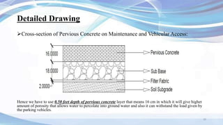
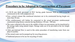
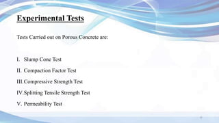
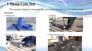
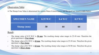
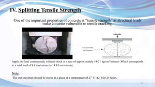
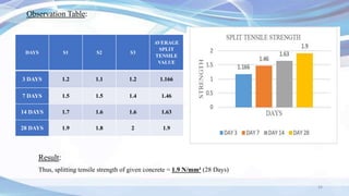
Use of 'Water Thirsty Concrete' in
Construction of Pavement to
Store, Recycle and Reuse Percolating Water
Presented by: Students of BE CIVIL
Ayushi Jha (44)
Mayur Sankpal (104)
Sumit Shinde (119)
Under the Guidance of
Prof. Sachin Pawar
1
Thirsty Concrete
Thirsty Concrete can be defined as a
concrete, manufactured using no fines
which can allow water to pass through it.
The thirsty concrete is also called as
Pervious concrete, Permeable concrete, No
fines concrete and Porous pavement.
The Main use of the thirsty concrete is to
transfer the stagnant water from the top
surface to the ground surface (Soil).
2
Objectives
 To allow the water to flow through itself and transfer it to the ground.
 To use for Low-volume Pavements, Residential roads, Sidewalks &
Pathways.
 To solve the problem of stagnant water significantly.
 To use as a water drain structure at the sides of highways.
 To increase the ground water level by allowing water through itself.
3
Properties of Thirsty Concrete
The mixture has a water-to-cement ratio of 0.28 to 0.40 with a void content of
15 to 25 percent.
The correct quantity of water in the concrete is critical.
 A low water-to-cement ratio will increase the strength of the concrete, but too
little water may cause surface failure.
As this concrete is sensitive to water content, the mixture should be field
checked.
4
History of Thirsty Concrete
Porous concrete was first used in 1800s in Europe as a pavement surfacing and
load bearing wall.
The initial use of porous concrete was at United Kingdom in 1852.
It regained popularity in 1920s for 2-storey homes in Scotland and England.
Use of porous concrete in Europe increased steadily due to scarcity of cement,
especially in the World War II era.
Lafarge Tarmac, a company based in the United Kingdom, was the first company
to design and construct the thirsty concrete in 2015.
5
Raw Materials
Cement Coarse Aggregate
Ordinary Portland Cement 12 mm Coarse Aggregates
Water Admixture (Silica Fume)
Normal Water Silica Fume
6
Mix Design
Materials Proportions (Kg/m3)
Cement (OPC or blended) 270 to 415
Aggregate 1190 to 1480
Water-Cement Ratio (by mass) 0.27 to 0.35
Fine-Coarse Aggregate Ratio (by mass) 0 to 1:1
Chemical admixtures (retarders) are commonly used and addition of fine aggregates will decrease the
void content and increase strength
7
Pervious Pavement Categories
8
Category Examples Loading Speed Risk
A
Landscaped areas, sidewalks and bike
paths (with no vehicular access),
miscellaneous pavement to accept run-
on from adjacent impervious areas (e.g.
roofs)
No vehicular loads N/A Low
B
Parking lots, park & ride areas,
maintenance access roads, scenic
overview areas, sidewalks and bike
paths (with maintenance/vehicular)
Few heavy loads
Low speed (less than
30 mph)
Low
C Rest areas, maintenance stations Moderate heavy loads Low speed Low
D
Shoulders, some low volume roads,
areas in front of noise barriers (beyond
the traveled way)
Moderate heavy loads High speed Medium
E Highways, weigh stations High heavy loads High speed High
Pervious Pavement Categories
 Zero for Category A (non-auto locations)
 0.50 feet for Category B auto areas
 0.70 feet for Category B truck areas
 0.70 feet for Category C truck areas
9
Detailed Drawing
10
Cross-section of Pervious Concrete on Maintenance and Vehicular Access:
Hence we have to use 0.50 feet depth of pervious concrete layer that means 16 cm in which it will give higher
amount of porosity that allows water to percolate into ground water and also it can withstand the load given by
the parking vehicles.
Procedure
 First add the aggregates and cement in the mixing tray and then gradually add the water.
 Start with little amount of water and keep adding a small amount of water, in installments. Keeping track of
amount of water added to achieve the consistency is suggested.
 After the ingredients are thoroughly mixed, squeeze a handful of pervious concrete to make a ball out of it.
The ball should hold together and the cement pastes should have a shine of it.
 Pervious concrete will be workable and will set up strong and permeable. If the paste does not have enough
water in it then the paste will appear dull and the ball will not hold; it will crumble.
 To fix this, add small amount of water in the mix and continue with adding small amount of water gradually
until desired workability is achieved.
 To fix this, mix in more aggregates and cement in the said proportions which is 3:1
 This perfectly mixed pervious concrete with correct amount of water-to-cement ratio is ready to place.
11
12
Too Much Amount of Water
Appropriate Amount of Water
Too Little Water
Result
M25 Grade of Concrete
Aggregate: 12 mm
Mix proportion ratio of 1:3 is to be adopted.
13
Water Cement Aggregate
0.35 1 3
Mix Proportion
Procedure to be Adopted in Construction of Pavement
A 20-30 mm thick pavement of PCC having grade between M20 to M30 is to be
constructed on the well compacted soil.
Now, vertical column like reinforced structures are to be constructed having height not
more than 50 mm.
This reinforcement will further be connected to the actual pavement reinforcement
constructed using thirsty concrete having thickness 150 mm - 300 mm.
The water collected in the area in the middle of these two pavements can be transferred to
the storage tanks using natural slopes. Storage tanks are to be provided at the low height
point only.
 Only gravitational flow is used in this entire procedure of transferring water from one
place to another.
This stored water can be pumped up for recycling process.
Traditional process to be use for recycling of water.
14
Experimental Tests
Tests Carried out on Porous Concrete are:
I. Slump Cone Test
II. Compaction Factor Test
III.Compressive Strength Test
IV.Splitting Tensile Strength Test
V. Permeability Test
15
I. Slump Cone Test
The concrete slump test measures the consistency of fresh concrete before it sets.
Procedure
1. Slump cone: 2. Tamping:
3. Removing Cone: 4. Height Measurement:
16
17
Collapse Shear True
In a collapse slump, the
concrete collapses
completely.
In a shear slump the top
portion of the concrete
shears off and slips sideways.
In a true slump the
concrete simply subsides,
keeping more or less to
shape.
Range: >100 mm Range: 50-90 mm Range: 25-50 mm
18
Observation Table:
 The Slump Cone Value is determined for various Water-Cement Ratios and the result are listed in table below-
Result:
1. The slump value of 0.35 W/C is 30 mm. The resulting slump value ranges in 25-50 mm. Therefore the
given specimen is True slump.
2. The slump value of 0.4 W/C is 44 mm. The resulting slump value ranges in 25-50 mm. Therefore the given
specimen is True slump.
3. The slump value of 0.5 W/C is 64 mm. The resulting slump value ranges in 50-90 mm. Therefore the given
specimen is Shear slump.
SPECIMEN NAME 0.35 W/C 0.4 W/C 0.5 W/C
Slump (mm) 30 44 64
II. Compaction Factor Test
Compaction factor test is the workability test for concrete conducted in laboratory.
Procedure: Compaction Factor Value = (W1-W) / (W2-W)
19
Compacting Factor Degree of Workability
0.7 to 0.8 Very Low Workability
0.8 to 0.85 Low Workability
0.85 to 0.95 Medium Workability
>0.95 High Workability
Range of Compacting Factor
20
Observation Table:
Result:
1. Compaction Factor Value for 0.35 W/C is 0.85. The value lies between 0.85 and 0.95. Therefore, Degree of Workability
is Medium.
2. Compaction Factor Value for 0.4 W/C is 0.74. The value lies between 0.7 and 0.8. Therefore, Degree of Workability is
Very low.
3. Compaction Factor Value for 0.5 W/C is 0.7. The value lies between 0.7 and 0.8. Therefore, Degree of Workability is
Very low.
W/C W (kg) W1 (kg) W2 (kg)
Compaction
Factor
0.35 5.4 11.0 12.0 0.85
0.4 5.4 11.2 13.2 0.74
0.5 5.4 10.3 12.5 0.7
III. Compressive Strength of Concrete
Compressive strength is the ability of material or structure to carry the loads on its
surface without any crack or deflection.
Procedure:
21
Cube Mould
Compression Testing Machine
Precautions for Tests:
The water for curing should be tested every 7 days and the temperature of the water must be at 27° C.
22
DAYS S1 S2 S3
AVERAGE
COMPRESSIVE
STRENGTH
(Kg/m3)
3 DAYS 6.9 7.32 7.28 7.16
7 DAYS 17.1 17.16 17.31 17.19
14 DAYS 22.1 23.4 23.1 22.87
28 DAYS 25.73 25.9 26.19 25.94
Observation Table:
Results of Concrete Cube Test:
Average compressive strength of the concrete cube = 7.16 N/mm2 (at 3 days)
Average compressive strength of the concrete cube = 17.19 N/mm2 (at 7 days)
Average compressive strength of the concrete cube = 22.87 N/mm2 (at 14 days)
Average compressive strength of the concrete cube = 25.94 N/mm2 (at 28 days)
IV. Splitting Tensile Strength
One of the important properties of concrete is “tensile strength” as structural loads
make concrete vulnerable to tensile cracking.
Note:
The test specimen should be stored in a place at a temperature of 27° C (±2°) for 24 hours.
23
Apply the load continuously without shock at a rate of approximately 14-21 kg/cm2/minute (Which corresponds
to a total load of 9.9 ton/minute to 14.85 ton/minute).
Observation Table:
24
DAYS S1 S2 S3
AVERAGE
SPLIT
TENSILE
VALUE
3 DAYS 1.2 1.1 1.2 1.166
7 DAYS 1.5 1.5 1.4 1.46
14 DAYS 1.7 1.6 1.6 1.63
28 DAYS 1.9 1.8 2 1.9
Result:
Thus, splitting tensile strength of given concrete = 1.9 N/mm² (28 Days)
V. Permeability Test
The test consists in subjecting the mortar or concrete specimen of known dimensions,
contained in a specially designed cell, to a known hydrostatic pressure from one side,
measuring the quantity of water percolating through it during a given interval of time and
computing the coefficient of permeability.
25
Water Pressure:
 1 bar (1 kg/cm2) for 48 hours.
 3 bars for next 24 hours.
 7 bars for next 24 hours.
Water-Cement Ratio Coefficient of Permeability
0.35 1 x 10⁻³
0.50 10 x 10-3
0.65 100 x 10-3
26
Observation Table:
SAMPLE
LENGTH
(cm)
DIA
(cm)
AREA
(cm2)
DISCHARGE
Q
(ml)
HEAD
H
(mm)
TIME
(sec)
CO-EFFICIENT
OF
PERMEABILITY
(X 10-3cm/sec)
1 30 15 176.51 3800 270 18 1.32
2 30 15 176.51 3800 270 16 1.49
3 30 15 176.51 3800 270 17 1.40
Permeability Test Calculation:
k = (Q x L) / (T x H x A) cm/s
Result:
1. Permeability of given concrete for sample 1 = 1.32 X 10⁻³cm/sec
2. Permeability of given concrete for sample 2 = 1.49 X 10⁻³cm/sec
3. Permeability of given concrete for sample 3 = 1.40 X 10⁻³cm/sec
Industrial Analysis
Maharashtra:
 Total number of industrial areas: 233
 Area covered by Industrial land: 53120 hectares
 Biggest MIDC – Tarapur; covering 1035 hectares of land and average rainfall of 2139 mm.
27
Industrial Analysis: Bharat Forge (Hadapsar)
 Total area : 80 acres
 Average Rainfall in Pune : 722 mm
 Open area (amount of area not covered by any shed slab): 50% of total area i.e. 40 acre
 Area in sq. m = 40*4046.8
= 161872 sq. m
 Volume of water that can be collected in period of year = Rainfall * Area
= 722 * 161872
= 116871584 litres
= 116871.584 cu.m
28
Transportation Analysis
Total length of roads in India: 589000 km
Highway length: 142126 km
Length of roads under construction: 65000 km
Total length of roads in Maharashtra: 267452 km
Highway length: 16000 km
Total amount of water that can be collected by constructing 1 km permeable concrete is calculated
as -
o Area in sq. m., of 1 km road length having width 7 m: 1000*6 = 6000 sq. m.
o Average rainfall in Mumbai: 2514 mm
o Volume of water = Area in sq. m * average rainfall
= 6000 * 2514
= 15084000 litres, i.e. 10584 cu. m.
Analysis for 3 prominent cities of Maharashtra is shown ahead…
29
Transportation Analysis for Prominent Cities in
Maharashtra for 1 Km Long And 7 m Wide Road
• Name of City
• Mumbai Name of City
• Mumbai
• Pune
• Nagpur
• Pune
• Nagpur
30
Name of City Mumbai Pune Nagpur
Average rainfall in mm 2514 722 1064
Water can be collected in cu. m. 15084 4332 6384
AVERAGE RAINFALL IN PROMINENT
CITIES OF MAHARASHTRA
0
500
1000
1500
2000
2500
3000
mumbai pune nagpur
rainfall
Advantages & Disadvantages
Advantages
 Effective surface runoff management
 Control over pollutants
 Ground water recharge
 Reduction in cost
 No standing water or ice development during
winter
 Extended pavement life due to well drained base
and reduced freeze-thaw
 Prevents polluted water from entering into stream
Disadvantages
 Traffic loads and volumes
 Lack off standard test method
 Runoff volumes
 Pollutant load
 Weight and traffic volume
31
Scope for Future Work
In the past, due to scarcity of cement, the pervious concrete has been used extensively.
But now-a-days, the usage of pervious concrete has gained its popularity due to many
advantages.
The urban areas all over the world have become CONCRETE JUNGLES. The discharge
of stormwater is very difficult in present conditions.
By using pervious concrete, we can recharge the groundwater table and the stormwater
disposal can also be done.
So, in future, to tackle aforesaid problems and to protect people from flood prone areas,
pervious concrete is one quite effective solution.
32
Applications
Parking Areas
Area with light traffic
Pedestrian Walkways
Green Houses
Swimming Pool Decks
Tennis Courts
Side Drains
Side Walks
33
Conclusion
The central goal of this project is to efficiently and effectively manage the excess
amount of water on land surfaces of various areas such as roads, sports courts,
parking lots with the excellent use of advancement in chemical technology. This
solution of implementing porous concrete technology will be quite useful in
critical situations like flood, storm, etc.
Thus, the thirsty concrete will play an important role in contributing as a worthy
answer towards the problems of everyday life, such as water management, water
logging, aqua disaster management and a notable amount of benefits in all aspects
would be hence gained.
34
References
[1] M. Harshavarthana Balaji, M.R.Amarnaath, R.A.Kavin, S. Jaya pradeep (2015). Design of Eco Friendly Pervious Concrete. International Journal of Civil
Engineering and Technology (IJCIET), ISSN, Volume 6, Issue 2, February (2015), pp. 22-29
[2] P.C.Balamurugan, R.Avinash, S.Kalaivani, K.Saran, S.Venkateswaran (2019). Experimental Probe on Thirsty Concrete Using Recycled Aggregate May 2019,
International Journal of Innovative Research in Technology (IJIRT), Volume 5 Issue 12. ISSN: 2349-6002
[3] Mr.Dipanjan Mukherjee (2014). Manage Storm Water by Using Porous Pavement IOSR Journal of Mechanical and Civil Engineering (IOSR-JMCE). e-ISSN: 2278-
1684,p-ISSN: 2320-334X, Volume 11, Issue 4 Ver. III (Jul- Aug. 2014), PP 01-03
[4] Carmen T. Agouridis, Jonathan A. Villines and Joe D. Luck (2011). Permeable Pavement for Stormwater Management. University of Kentucky College of
Agriculture, Lexington, KY, 40564.
[5] Abrar Ahmed Khan, Sayed Sarfaraz, Syed Bilal Mansoori, Avinash Patel K L, Poornima K B, Dinesh S Magnur (2017). Study on Porous Concrete with Course
Aggregate and Fine Aggregate Mix Proportions. International Journal of Engineering Research & Technology (IJERT). ISSN: 2278-0181, Vol. 6 Issue 05, May – 2017
[6] Darshan S. Shah, Prof. Jayeshkumar Pitroda, Prof. J. J. Bhavsar (2013). Pervious Concrete: New Era For Rural Road Pavement. International Journal of
Engineering Trends and Technology (IJETT) – Volume 4 Issue 8- August 2013
35
[7] Prof. Shilpi S. Bhuinyan, Shreyance Luniya, Mithila Mane, Smit Modi, Rushikesh Tapkir (2019). An Experimental Study on Strength and Properties of Thirsty
Concrete. International Journal Of Innovative Research In Technology (IJIRT) Volume 6 Issue 1 - ISSN: 2349-6002 June 2019
[8] Jaydeepkumar R. Prajapati, Dr. Jayeshkumar R. Pitroda, Prof. Amitkumar D. Raval (2019). Experimental Study On Pervious Concrete With Fly Ash And Metakaolin.
Journal of Emerging Technologies and Innovative Research (JETIR) - Volume 6, Issue 5 - May 2019
[9] Arun. H, Franglin Jose. L, Joegin Raj. K. R, Julius Walter. A.G, M. Murugalingam. (2016). Experimental Investigation On Increasing The Strength Of Pervious
Concrete By Varying The Mix Ingredients, International Journal of Advances in Mechanical and Civil Engineering, ISSN: 2394-2827 Volume-3, Issue-3, Jun.-2016
[10] An Cheng, Hui-Mi Hsu, Sao-Jeng Chao, And Kae-Long Lin (2011). Experimental study on properties of pervious concrete made with recycled aggregate’
International Journal of Pavement Research And Technology Vol.4 No.2, 2011
[11] L. K. Crouch, P.E.; Jordan Pitt; And Ryan Hewitt (2007. Aggregate effects on pervious portland cement concrete static modulus of elasticity” Journal Of Materials
In Civil Engineering Volume 19(7), 561-568 - 2007
36
THANK YOU !
37

Thirsty Concrete application in Road pavement

  • 1.
    Use of 'WaterThirsty Concrete' in Construction of Pavement to Store, Recycle and Reuse Percolating Water Presented by: Students of BE CIVIL Ayushi Jha (44) Mayur Sankpal (104) Sumit Shinde (119) Under the Guidance of Prof. Sachin Pawar 1
  • 2.
    Thirsty Concrete Thirsty Concretecan be defined as a concrete, manufactured using no fines which can allow water to pass through it. The thirsty concrete is also called as Pervious concrete, Permeable concrete, No fines concrete and Porous pavement. The Main use of the thirsty concrete is to transfer the stagnant water from the top surface to the ground surface (Soil). 2
  • 3.
    Objectives  To allowthe water to flow through itself and transfer it to the ground.  To use for Low-volume Pavements, Residential roads, Sidewalks & Pathways.  To solve the problem of stagnant water significantly.  To use as a water drain structure at the sides of highways.  To increase the ground water level by allowing water through itself. 3
  • 4.
    Properties of ThirstyConcrete The mixture has a water-to-cement ratio of 0.28 to 0.40 with a void content of 15 to 25 percent. The correct quantity of water in the concrete is critical.  A low water-to-cement ratio will increase the strength of the concrete, but too little water may cause surface failure. As this concrete is sensitive to water content, the mixture should be field checked. 4
  • 5.
    History of ThirstyConcrete Porous concrete was first used in 1800s in Europe as a pavement surfacing and load bearing wall. The initial use of porous concrete was at United Kingdom in 1852. It regained popularity in 1920s for 2-storey homes in Scotland and England. Use of porous concrete in Europe increased steadily due to scarcity of cement, especially in the World War II era. Lafarge Tarmac, a company based in the United Kingdom, was the first company to design and construct the thirsty concrete in 2015. 5
  • 6.
    Raw Materials Cement CoarseAggregate Ordinary Portland Cement 12 mm Coarse Aggregates Water Admixture (Silica Fume) Normal Water Silica Fume 6
  • 7.
    Mix Design Materials Proportions(Kg/m3) Cement (OPC or blended) 270 to 415 Aggregate 1190 to 1480 Water-Cement Ratio (by mass) 0.27 to 0.35 Fine-Coarse Aggregate Ratio (by mass) 0 to 1:1 Chemical admixtures (retarders) are commonly used and addition of fine aggregates will decrease the void content and increase strength 7
  • 8.
    Pervious Pavement Categories 8 CategoryExamples Loading Speed Risk A Landscaped areas, sidewalks and bike paths (with no vehicular access), miscellaneous pavement to accept run- on from adjacent impervious areas (e.g. roofs) No vehicular loads N/A Low B Parking lots, park & ride areas, maintenance access roads, scenic overview areas, sidewalks and bike paths (with maintenance/vehicular) Few heavy loads Low speed (less than 30 mph) Low C Rest areas, maintenance stations Moderate heavy loads Low speed Low D Shoulders, some low volume roads, areas in front of noise barriers (beyond the traveled way) Moderate heavy loads High speed Medium E Highways, weigh stations High heavy loads High speed High
  • 9.
    Pervious Pavement Categories Zero for Category A (non-auto locations)  0.50 feet for Category B auto areas  0.70 feet for Category B truck areas  0.70 feet for Category C truck areas 9
  • 10.
    Detailed Drawing 10 Cross-section ofPervious Concrete on Maintenance and Vehicular Access: Hence we have to use 0.50 feet depth of pervious concrete layer that means 16 cm in which it will give higher amount of porosity that allows water to percolate into ground water and also it can withstand the load given by the parking vehicles.
  • 11.
    Procedure  First addthe aggregates and cement in the mixing tray and then gradually add the water.  Start with little amount of water and keep adding a small amount of water, in installments. Keeping track of amount of water added to achieve the consistency is suggested.  After the ingredients are thoroughly mixed, squeeze a handful of pervious concrete to make a ball out of it. The ball should hold together and the cement pastes should have a shine of it.  Pervious concrete will be workable and will set up strong and permeable. If the paste does not have enough water in it then the paste will appear dull and the ball will not hold; it will crumble.  To fix this, add small amount of water in the mix and continue with adding small amount of water gradually until desired workability is achieved.  To fix this, mix in more aggregates and cement in the said proportions which is 3:1  This perfectly mixed pervious concrete with correct amount of water-to-cement ratio is ready to place. 11
  • 12.
    12 Too Much Amountof Water Appropriate Amount of Water Too Little Water
  • 13.
    Result M25 Grade ofConcrete Aggregate: 12 mm Mix proportion ratio of 1:3 is to be adopted. 13 Water Cement Aggregate 0.35 1 3 Mix Proportion
  • 14.
    Procedure to beAdopted in Construction of Pavement A 20-30 mm thick pavement of PCC having grade between M20 to M30 is to be constructed on the well compacted soil. Now, vertical column like reinforced structures are to be constructed having height not more than 50 mm. This reinforcement will further be connected to the actual pavement reinforcement constructed using thirsty concrete having thickness 150 mm - 300 mm. The water collected in the area in the middle of these two pavements can be transferred to the storage tanks using natural slopes. Storage tanks are to be provided at the low height point only.  Only gravitational flow is used in this entire procedure of transferring water from one place to another. This stored water can be pumped up for recycling process. Traditional process to be use for recycling of water. 14
  • 15.
    Experimental Tests Tests Carriedout on Porous Concrete are: I. Slump Cone Test II. Compaction Factor Test III.Compressive Strength Test IV.Splitting Tensile Strength Test V. Permeability Test 15
  • 16.
    I. Slump ConeTest The concrete slump test measures the consistency of fresh concrete before it sets. Procedure 1. Slump cone: 2. Tamping: 3. Removing Cone: 4. Height Measurement: 16
  • 17.
    17 Collapse Shear True Ina collapse slump, the concrete collapses completely. In a shear slump the top portion of the concrete shears off and slips sideways. In a true slump the concrete simply subsides, keeping more or less to shape. Range: >100 mm Range: 50-90 mm Range: 25-50 mm
  • 18.
    18 Observation Table:  TheSlump Cone Value is determined for various Water-Cement Ratios and the result are listed in table below- Result: 1. The slump value of 0.35 W/C is 30 mm. The resulting slump value ranges in 25-50 mm. Therefore the given specimen is True slump. 2. The slump value of 0.4 W/C is 44 mm. The resulting slump value ranges in 25-50 mm. Therefore the given specimen is True slump. 3. The slump value of 0.5 W/C is 64 mm. The resulting slump value ranges in 50-90 mm. Therefore the given specimen is Shear slump. SPECIMEN NAME 0.35 W/C 0.4 W/C 0.5 W/C Slump (mm) 30 44 64
  • 19.
    II. Compaction FactorTest Compaction factor test is the workability test for concrete conducted in laboratory. Procedure: Compaction Factor Value = (W1-W) / (W2-W) 19 Compacting Factor Degree of Workability 0.7 to 0.8 Very Low Workability 0.8 to 0.85 Low Workability 0.85 to 0.95 Medium Workability >0.95 High Workability Range of Compacting Factor
  • 20.
    20 Observation Table: Result: 1. CompactionFactor Value for 0.35 W/C is 0.85. The value lies between 0.85 and 0.95. Therefore, Degree of Workability is Medium. 2. Compaction Factor Value for 0.4 W/C is 0.74. The value lies between 0.7 and 0.8. Therefore, Degree of Workability is Very low. 3. Compaction Factor Value for 0.5 W/C is 0.7. The value lies between 0.7 and 0.8. Therefore, Degree of Workability is Very low. W/C W (kg) W1 (kg) W2 (kg) Compaction Factor 0.35 5.4 11.0 12.0 0.85 0.4 5.4 11.2 13.2 0.74 0.5 5.4 10.3 12.5 0.7
  • 21.
    III. Compressive Strengthof Concrete Compressive strength is the ability of material or structure to carry the loads on its surface without any crack or deflection. Procedure: 21 Cube Mould Compression Testing Machine Precautions for Tests: The water for curing should be tested every 7 days and the temperature of the water must be at 27° C.
  • 22.
    22 DAYS S1 S2S3 AVERAGE COMPRESSIVE STRENGTH (Kg/m3) 3 DAYS 6.9 7.32 7.28 7.16 7 DAYS 17.1 17.16 17.31 17.19 14 DAYS 22.1 23.4 23.1 22.87 28 DAYS 25.73 25.9 26.19 25.94 Observation Table: Results of Concrete Cube Test: Average compressive strength of the concrete cube = 7.16 N/mm2 (at 3 days) Average compressive strength of the concrete cube = 17.19 N/mm2 (at 7 days) Average compressive strength of the concrete cube = 22.87 N/mm2 (at 14 days) Average compressive strength of the concrete cube = 25.94 N/mm2 (at 28 days)
  • 23.
    IV. Splitting TensileStrength One of the important properties of concrete is “tensile strength” as structural loads make concrete vulnerable to tensile cracking. Note: The test specimen should be stored in a place at a temperature of 27° C (±2°) for 24 hours. 23 Apply the load continuously without shock at a rate of approximately 14-21 kg/cm2/minute (Which corresponds to a total load of 9.9 ton/minute to 14.85 ton/minute).
  • 24.
    Observation Table: 24 DAYS S1S2 S3 AVERAGE SPLIT TENSILE VALUE 3 DAYS 1.2 1.1 1.2 1.166 7 DAYS 1.5 1.5 1.4 1.46 14 DAYS 1.7 1.6 1.6 1.63 28 DAYS 1.9 1.8 2 1.9 Result: Thus, splitting tensile strength of given concrete = 1.9 N/mm² (28 Days)
  • 25.
    V. Permeability Test Thetest consists in subjecting the mortar or concrete specimen of known dimensions, contained in a specially designed cell, to a known hydrostatic pressure from one side, measuring the quantity of water percolating through it during a given interval of time and computing the coefficient of permeability. 25 Water Pressure:  1 bar (1 kg/cm2) for 48 hours.  3 bars for next 24 hours.  7 bars for next 24 hours. Water-Cement Ratio Coefficient of Permeability 0.35 1 x 10⁻³ 0.50 10 x 10-3 0.65 100 x 10-3
  • 26.
    26 Observation Table: SAMPLE LENGTH (cm) DIA (cm) AREA (cm2) DISCHARGE Q (ml) HEAD H (mm) TIME (sec) CO-EFFICIENT OF PERMEABILITY (X 10-3cm/sec) 130 15 176.51 3800 270 18 1.32 2 30 15 176.51 3800 270 16 1.49 3 30 15 176.51 3800 270 17 1.40 Permeability Test Calculation: k = (Q x L) / (T x H x A) cm/s Result: 1. Permeability of given concrete for sample 1 = 1.32 X 10⁻³cm/sec 2. Permeability of given concrete for sample 2 = 1.49 X 10⁻³cm/sec 3. Permeability of given concrete for sample 3 = 1.40 X 10⁻³cm/sec
  • 27.
    Industrial Analysis Maharashtra:  Totalnumber of industrial areas: 233  Area covered by Industrial land: 53120 hectares  Biggest MIDC – Tarapur; covering 1035 hectares of land and average rainfall of 2139 mm. 27
  • 28.
    Industrial Analysis: BharatForge (Hadapsar)  Total area : 80 acres  Average Rainfall in Pune : 722 mm  Open area (amount of area not covered by any shed slab): 50% of total area i.e. 40 acre  Area in sq. m = 40*4046.8 = 161872 sq. m  Volume of water that can be collected in period of year = Rainfall * Area = 722 * 161872 = 116871584 litres = 116871.584 cu.m 28
  • 29.
    Transportation Analysis Total lengthof roads in India: 589000 km Highway length: 142126 km Length of roads under construction: 65000 km Total length of roads in Maharashtra: 267452 km Highway length: 16000 km Total amount of water that can be collected by constructing 1 km permeable concrete is calculated as - o Area in sq. m., of 1 km road length having width 7 m: 1000*6 = 6000 sq. m. o Average rainfall in Mumbai: 2514 mm o Volume of water = Area in sq. m * average rainfall = 6000 * 2514 = 15084000 litres, i.e. 10584 cu. m. Analysis for 3 prominent cities of Maharashtra is shown ahead… 29
  • 30.
    Transportation Analysis forProminent Cities in Maharashtra for 1 Km Long And 7 m Wide Road • Name of City • Mumbai Name of City • Mumbai • Pune • Nagpur • Pune • Nagpur 30 Name of City Mumbai Pune Nagpur Average rainfall in mm 2514 722 1064 Water can be collected in cu. m. 15084 4332 6384 AVERAGE RAINFALL IN PROMINENT CITIES OF MAHARASHTRA 0 500 1000 1500 2000 2500 3000 mumbai pune nagpur rainfall
  • 31.
    Advantages & Disadvantages Advantages Effective surface runoff management  Control over pollutants  Ground water recharge  Reduction in cost  No standing water or ice development during winter  Extended pavement life due to well drained base and reduced freeze-thaw  Prevents polluted water from entering into stream Disadvantages  Traffic loads and volumes  Lack off standard test method  Runoff volumes  Pollutant load  Weight and traffic volume 31
  • 32.
    Scope for FutureWork In the past, due to scarcity of cement, the pervious concrete has been used extensively. But now-a-days, the usage of pervious concrete has gained its popularity due to many advantages. The urban areas all over the world have become CONCRETE JUNGLES. The discharge of stormwater is very difficult in present conditions. By using pervious concrete, we can recharge the groundwater table and the stormwater disposal can also be done. So, in future, to tackle aforesaid problems and to protect people from flood prone areas, pervious concrete is one quite effective solution. 32
  • 33.
    Applications Parking Areas Area withlight traffic Pedestrian Walkways Green Houses Swimming Pool Decks Tennis Courts Side Drains Side Walks 33
  • 34.
    Conclusion The central goalof this project is to efficiently and effectively manage the excess amount of water on land surfaces of various areas such as roads, sports courts, parking lots with the excellent use of advancement in chemical technology. This solution of implementing porous concrete technology will be quite useful in critical situations like flood, storm, etc. Thus, the thirsty concrete will play an important role in contributing as a worthy answer towards the problems of everyday life, such as water management, water logging, aqua disaster management and a notable amount of benefits in all aspects would be hence gained. 34
  • 35.
    References [1] M. HarshavarthanaBalaji, M.R.Amarnaath, R.A.Kavin, S. Jaya pradeep (2015). Design of Eco Friendly Pervious Concrete. International Journal of Civil Engineering and Technology (IJCIET), ISSN, Volume 6, Issue 2, February (2015), pp. 22-29 [2] P.C.Balamurugan, R.Avinash, S.Kalaivani, K.Saran, S.Venkateswaran (2019). Experimental Probe on Thirsty Concrete Using Recycled Aggregate May 2019, International Journal of Innovative Research in Technology (IJIRT), Volume 5 Issue 12. ISSN: 2349-6002 [3] Mr.Dipanjan Mukherjee (2014). Manage Storm Water by Using Porous Pavement IOSR Journal of Mechanical and Civil Engineering (IOSR-JMCE). e-ISSN: 2278- 1684,p-ISSN: 2320-334X, Volume 11, Issue 4 Ver. III (Jul- Aug. 2014), PP 01-03 [4] Carmen T. Agouridis, Jonathan A. Villines and Joe D. Luck (2011). Permeable Pavement for Stormwater Management. University of Kentucky College of Agriculture, Lexington, KY, 40564. [5] Abrar Ahmed Khan, Sayed Sarfaraz, Syed Bilal Mansoori, Avinash Patel K L, Poornima K B, Dinesh S Magnur (2017). Study on Porous Concrete with Course Aggregate and Fine Aggregate Mix Proportions. International Journal of Engineering Research & Technology (IJERT). ISSN: 2278-0181, Vol. 6 Issue 05, May – 2017 [6] Darshan S. Shah, Prof. Jayeshkumar Pitroda, Prof. J. J. Bhavsar (2013). Pervious Concrete: New Era For Rural Road Pavement. International Journal of Engineering Trends and Technology (IJETT) – Volume 4 Issue 8- August 2013 35
  • 36.
    [7] Prof. ShilpiS. Bhuinyan, Shreyance Luniya, Mithila Mane, Smit Modi, Rushikesh Tapkir (2019). An Experimental Study on Strength and Properties of Thirsty Concrete. International Journal Of Innovative Research In Technology (IJIRT) Volume 6 Issue 1 - ISSN: 2349-6002 June 2019 [8] Jaydeepkumar R. Prajapati, Dr. Jayeshkumar R. Pitroda, Prof. Amitkumar D. Raval (2019). Experimental Study On Pervious Concrete With Fly Ash And Metakaolin. Journal of Emerging Technologies and Innovative Research (JETIR) - Volume 6, Issue 5 - May 2019 [9] Arun. H, Franglin Jose. L, Joegin Raj. K. R, Julius Walter. A.G, M. Murugalingam. (2016). Experimental Investigation On Increasing The Strength Of Pervious Concrete By Varying The Mix Ingredients, International Journal of Advances in Mechanical and Civil Engineering, ISSN: 2394-2827 Volume-3, Issue-3, Jun.-2016 [10] An Cheng, Hui-Mi Hsu, Sao-Jeng Chao, And Kae-Long Lin (2011). Experimental study on properties of pervious concrete made with recycled aggregate’ International Journal of Pavement Research And Technology Vol.4 No.2, 2011 [11] L. K. Crouch, P.E.; Jordan Pitt; And Ryan Hewitt (2007. Aggregate effects on pervious portland cement concrete static modulus of elasticity” Journal Of Materials In Civil Engineering Volume 19(7), 561-568 - 2007 36
  • 37.