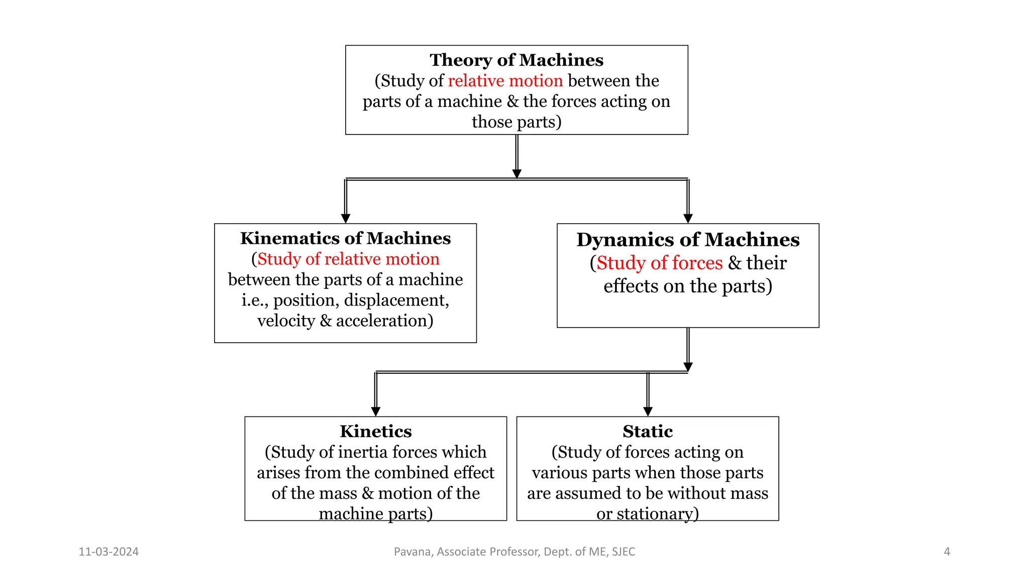
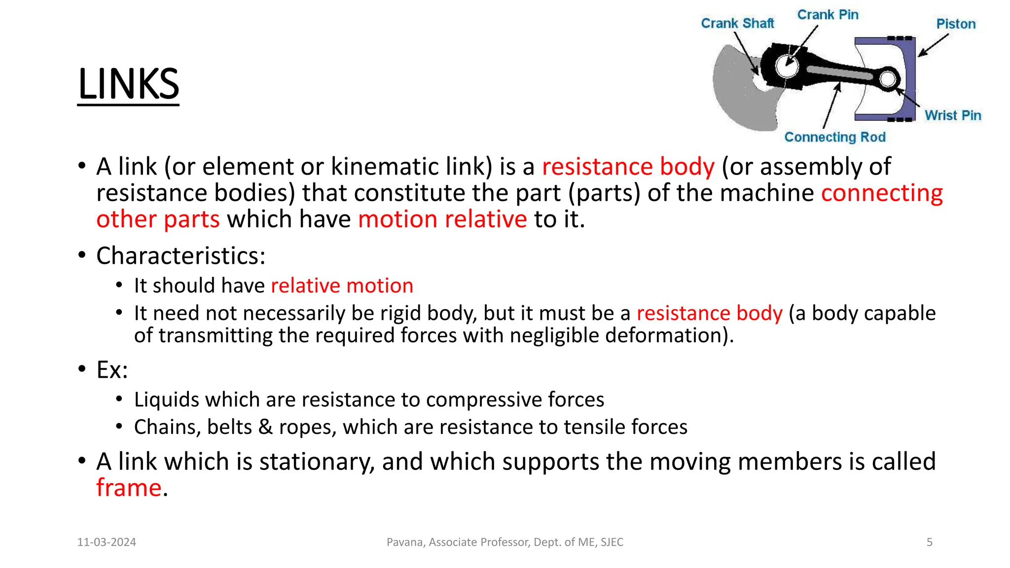
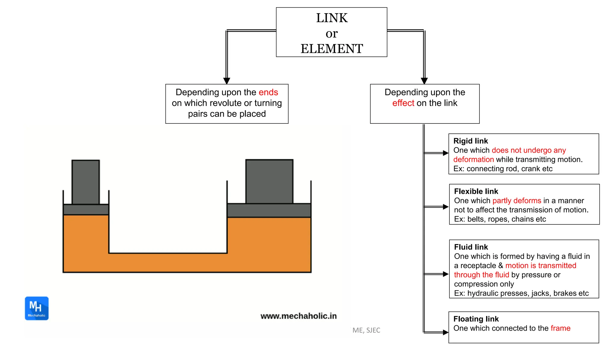
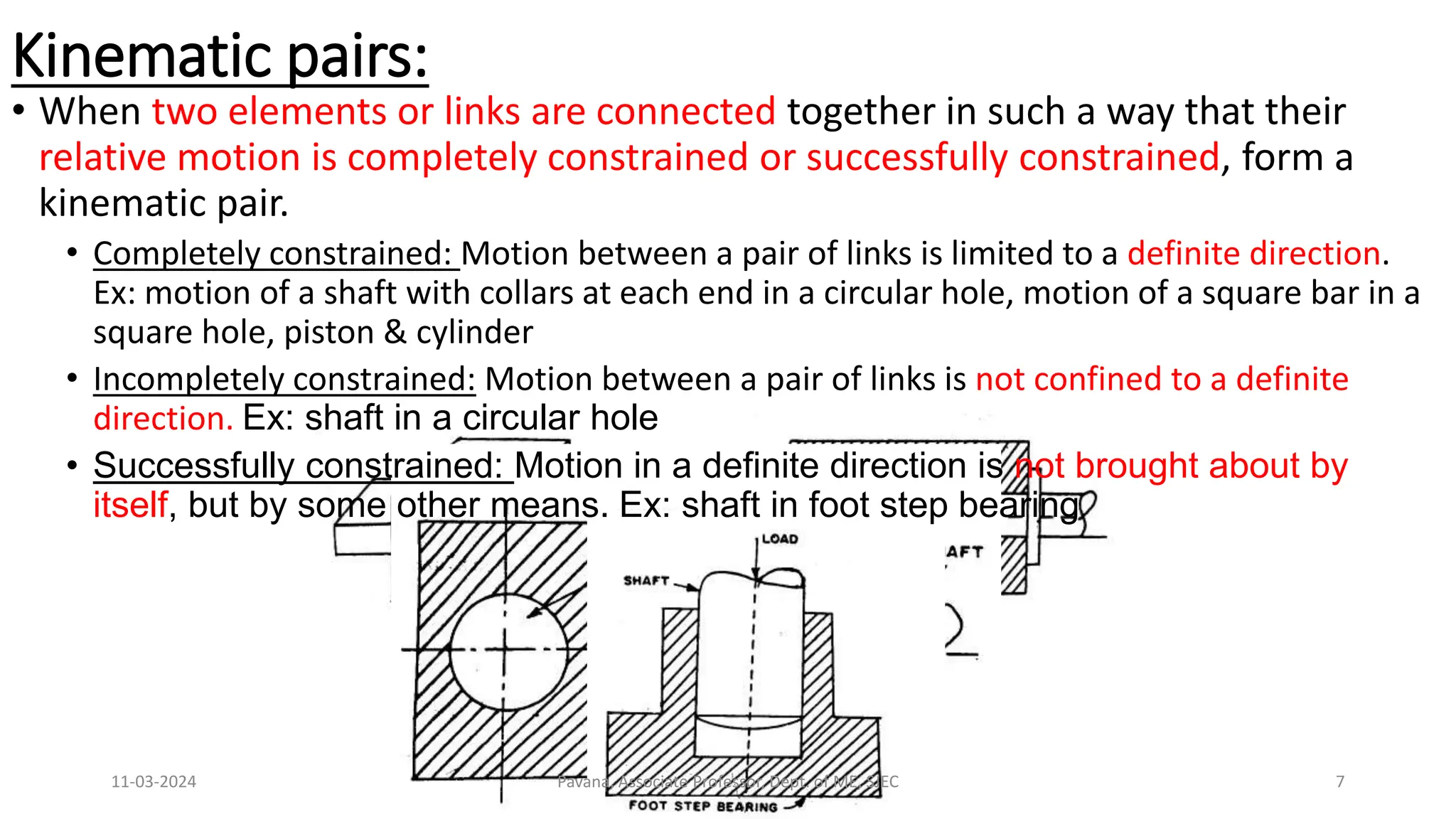
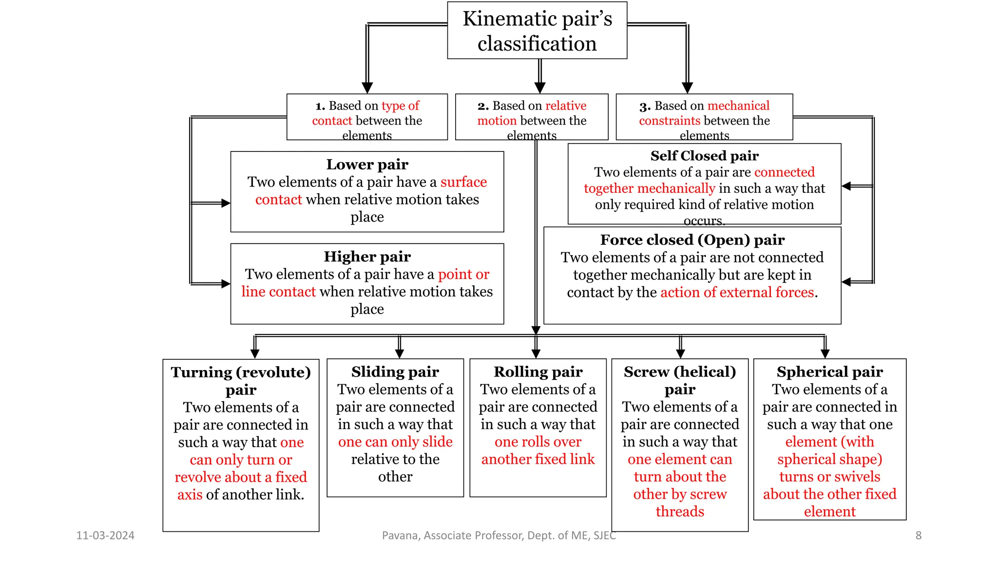
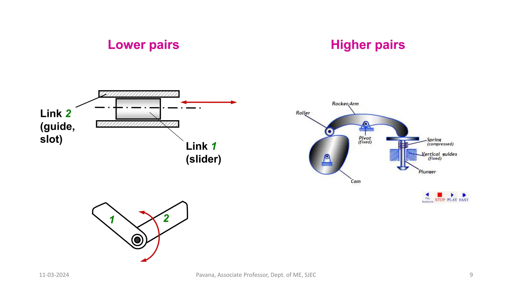
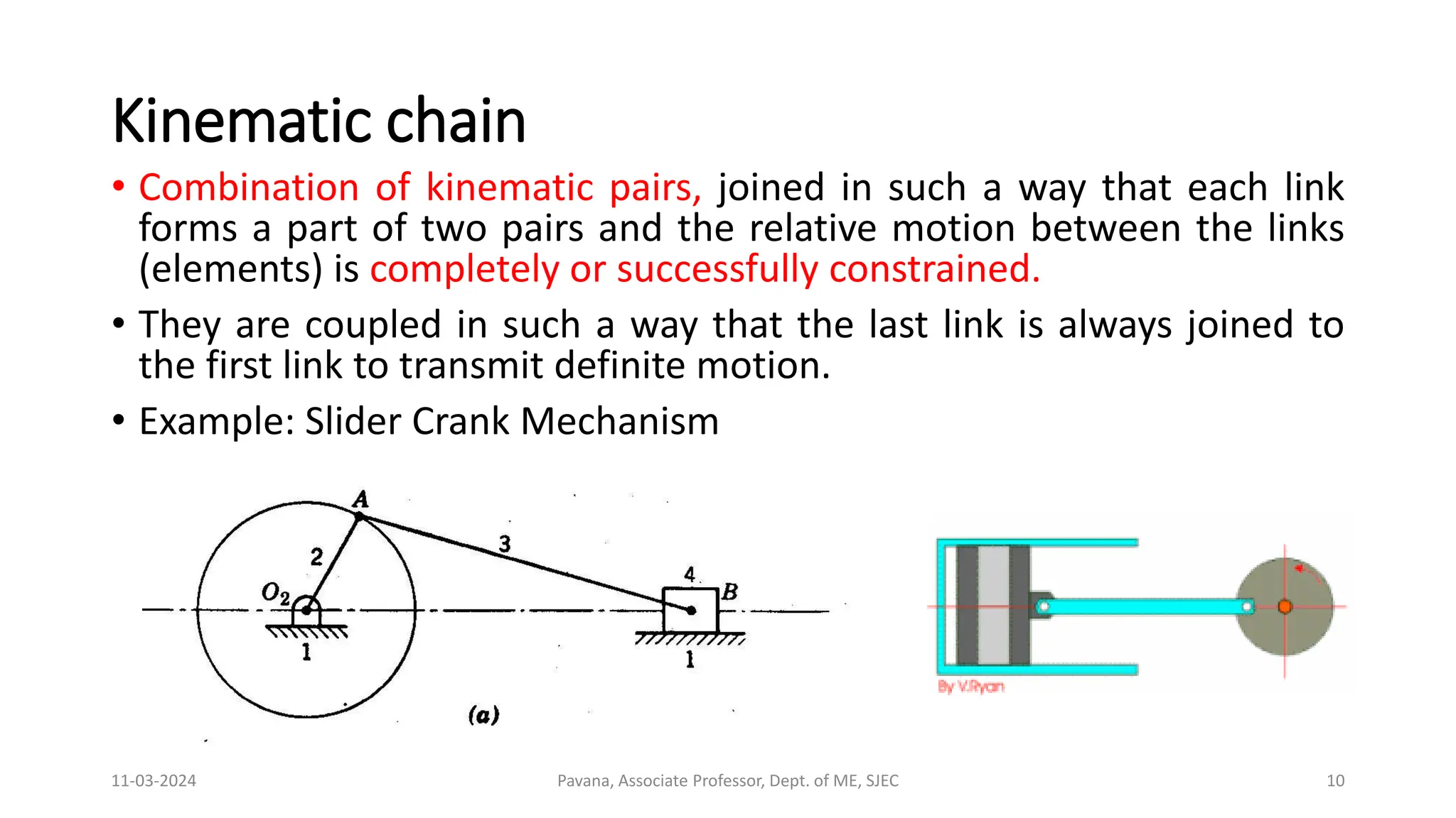
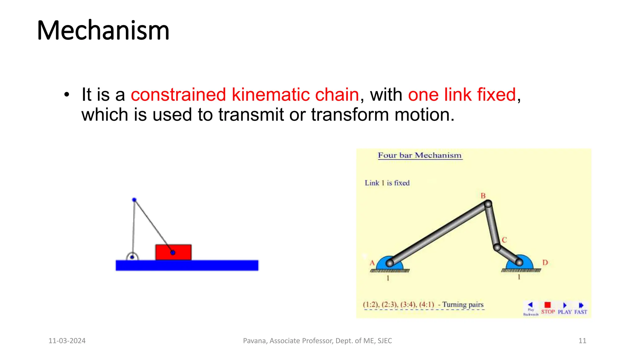
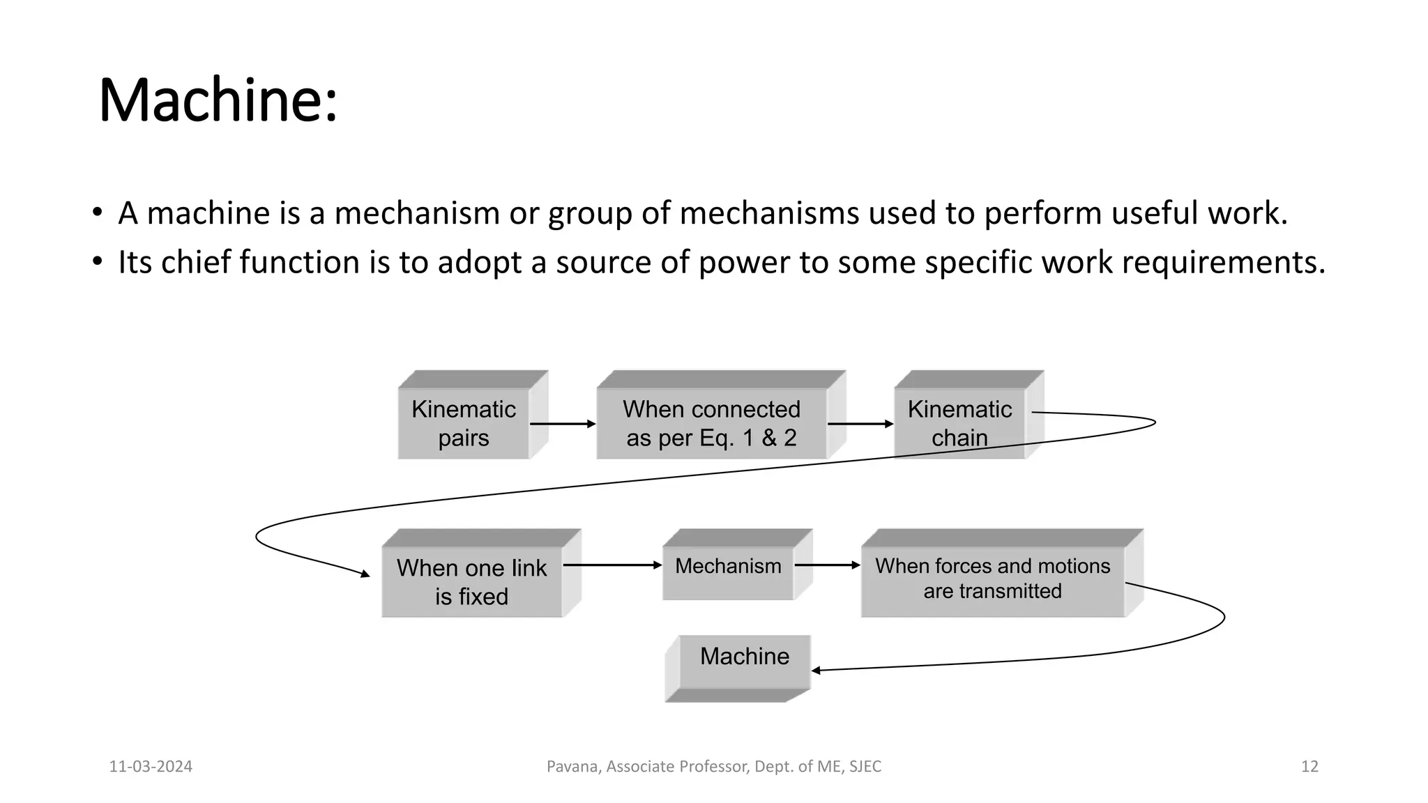
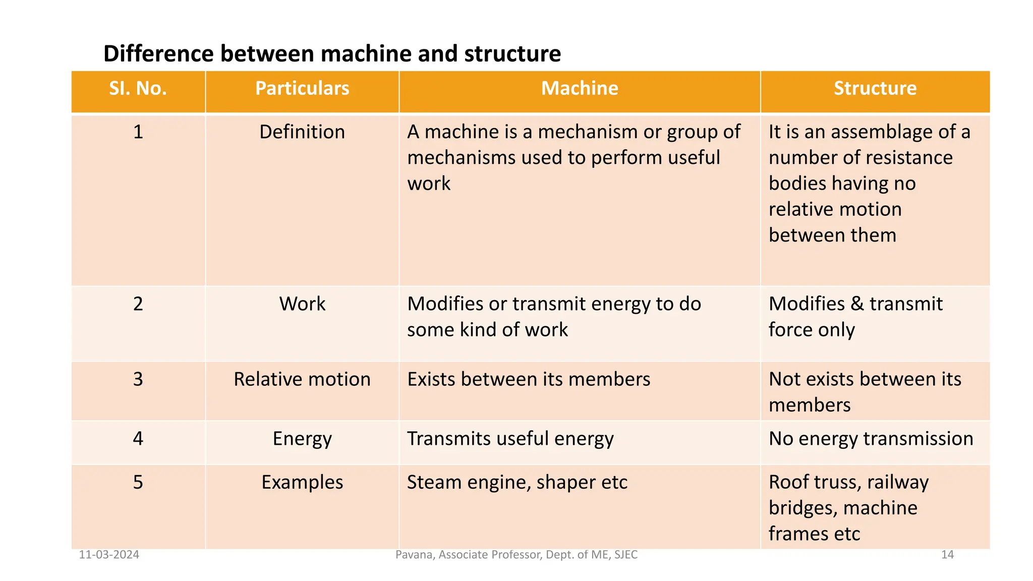
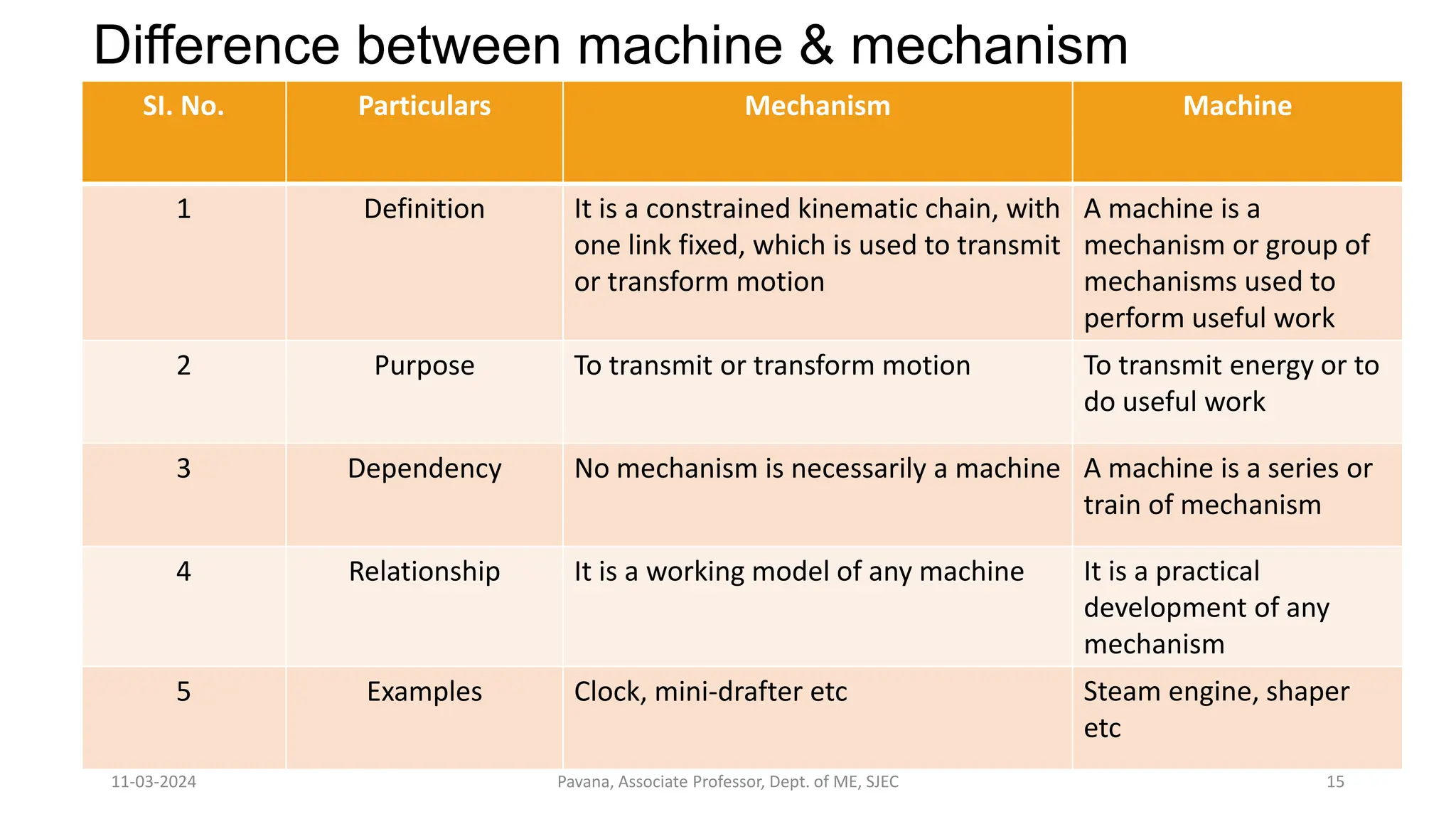
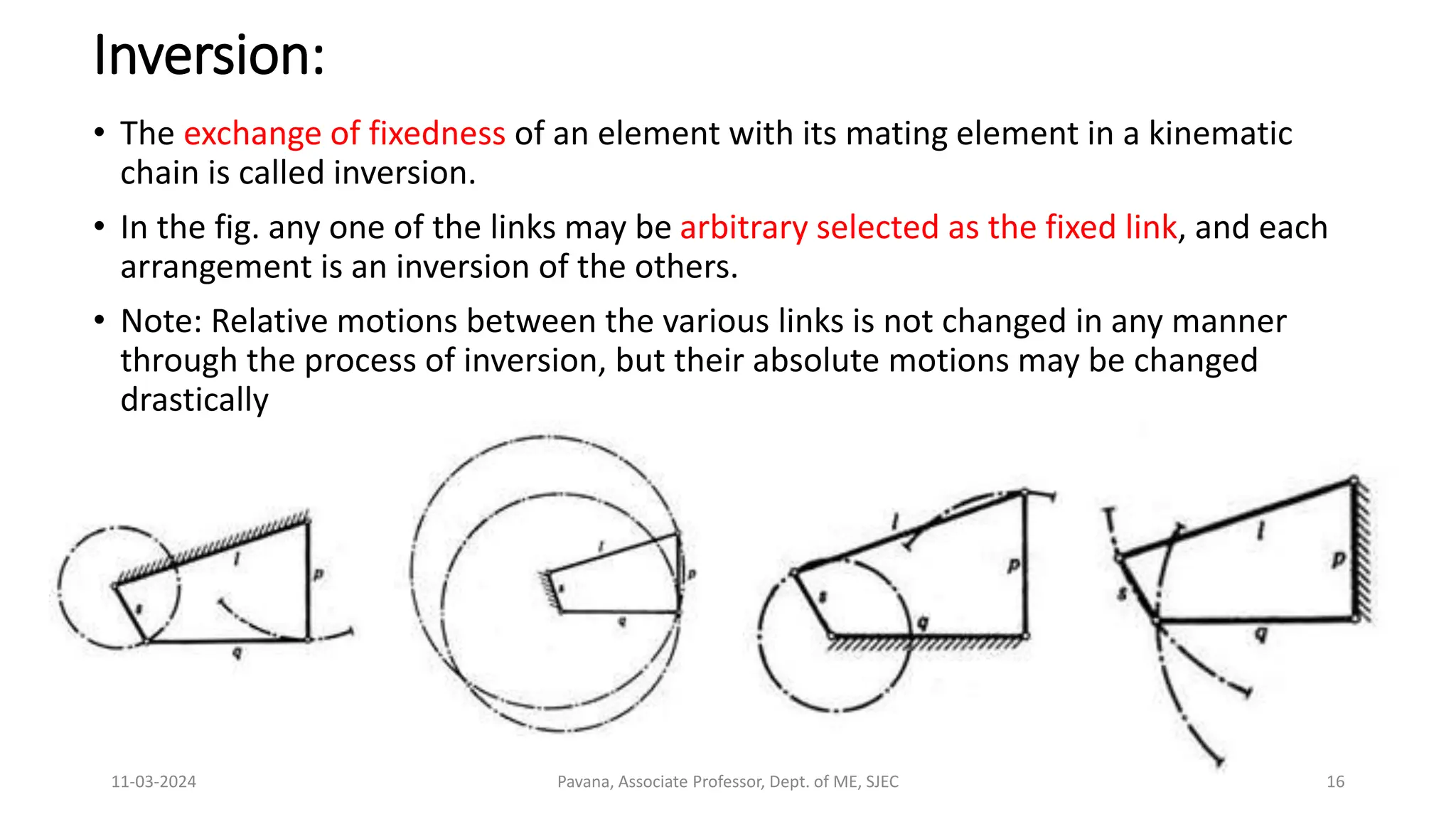
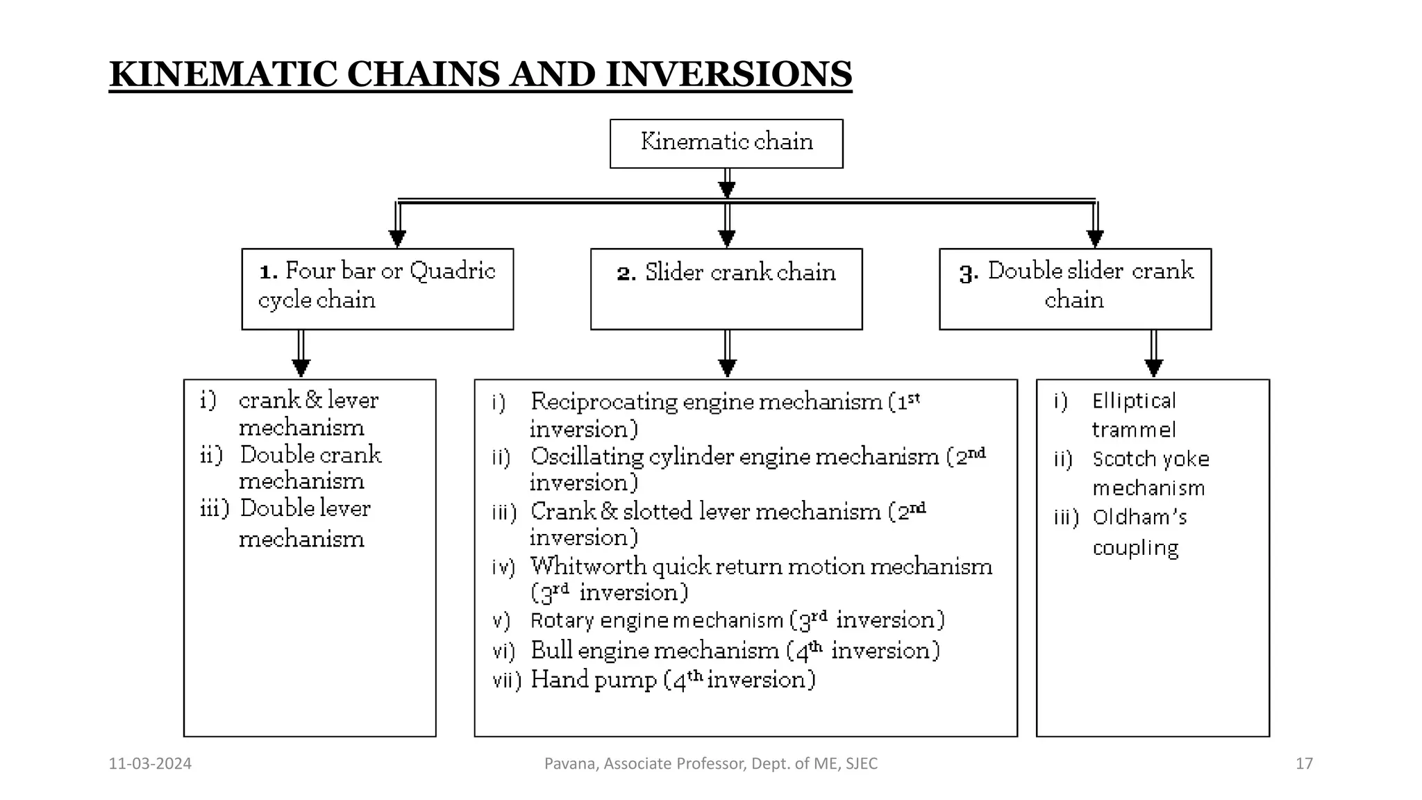
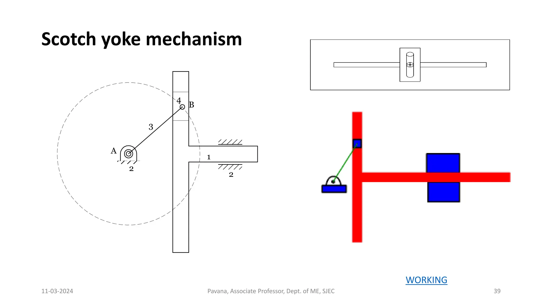
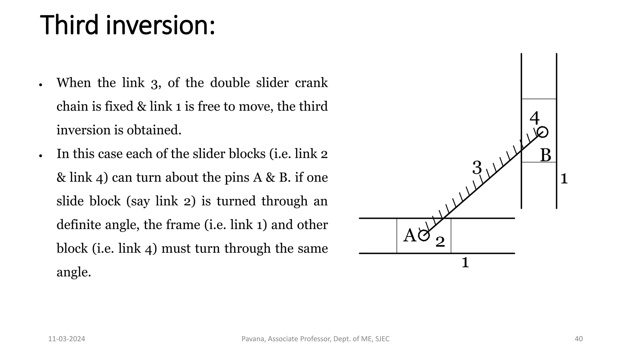
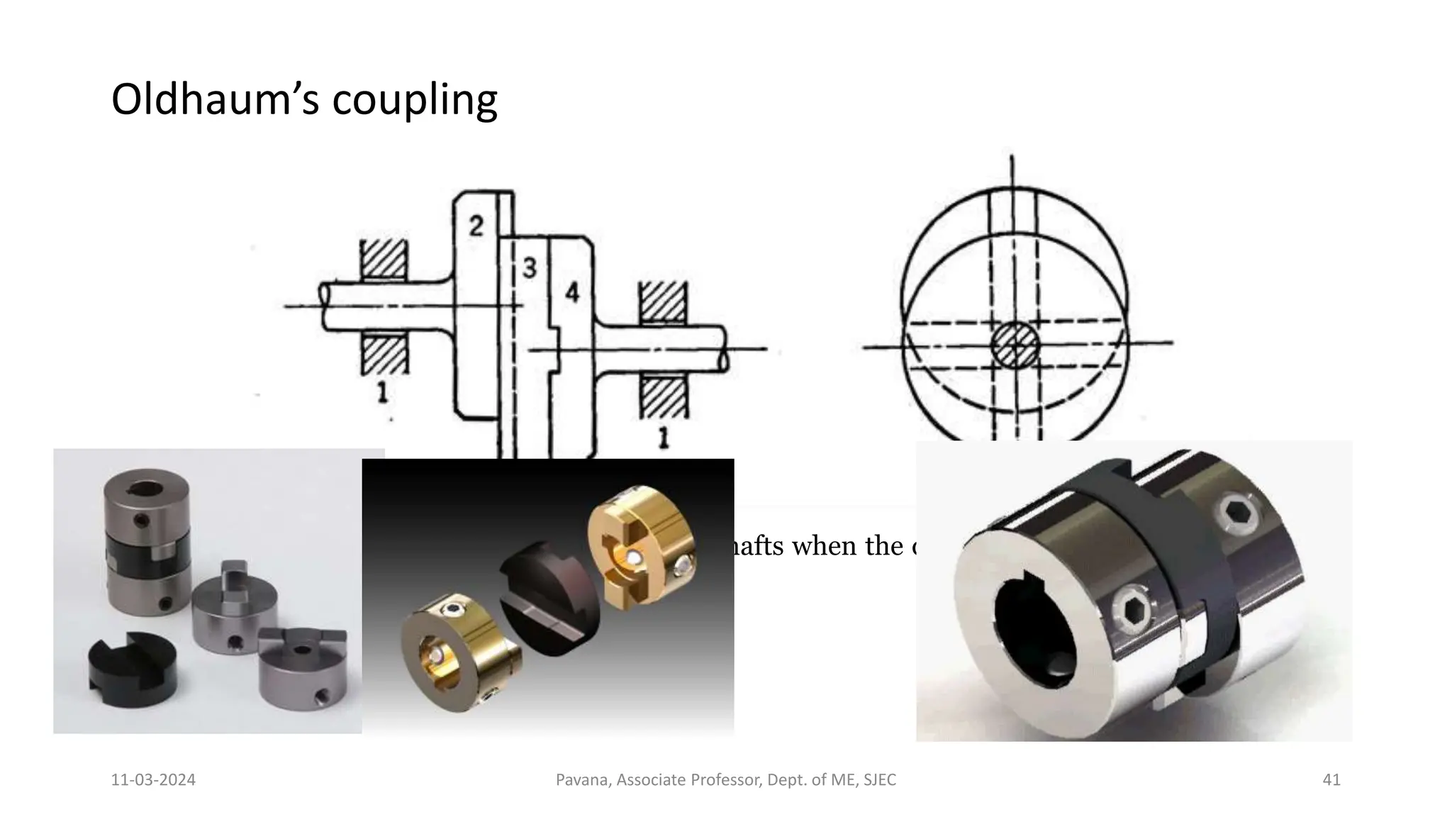
The theory of machines is a branch of mechanical engineering that deals with the study of mechanisms and their applications in various systems. It encompasses the analysis, design, and optimization of mechanisms such as gears, linkages, cams, and mechanisms to transmit motion and forces. This field explores principles of kinematics, dynamics, and control to understand the behavior and performance of machines, aiding in the development of efficient and functional mechanical systems for various industries.
Introduction to IEEE STANDARDS and its different types.pptx
Theory Of Machines in Mechanical Engineering
1. Theory of Machines
(21MEC503)
Course objectives
Students will
• Know the principles of kinematic pairs, chains and their classification, DOF and inversions of kinematic chains
• Impart knowledge on various types of links and synthesis
• Know the necessity of balancing in high-speed rotating components
• To familiarize principles of cams and its profiles, governors, gyroscope and gears
Course outcomes
Students will be able to
1. Interpret various concepts and terminologies of machines, mechanisms and calculate mobility of joints within
mechanisms.
2. Examine and evaluate the force, velocity on links of four bar, crank slider mechanism subjected to external forces.
3. Solve problems concerning static and dynamic balancing of systems involving rotating masses
4. Analyze the effect of gyroscopic couple on rotors, ships, aero planes and automobiles
5. Analyze and understand concepts on cams, gear, gear trains and to become acquainted with gear standardization and
design specifications.
6. Demonstrate the working principle of governors and force analysis of Porter & Hartnell governor.
2. MODULE 1
• Introduction: Definitions: Link, kinematic pairs, kinematic chain,
mechanism, structure, degrees of freedom, Classification links,
Classification of pairs based on type of relative motion, Grubler's
criterion, mobility of mechanism, Grashoff’s criteria, inversions of
Grashoff’s chain.
• Mechanisms: Quick return motion Mechanisms-Drag link mechanism,
Whitworth mechanism and Crank and slotted lever Mechanism.
Intermittent Motion mechanisms: Geneva wheel mechanism, Ratchet
and Pawl mechanism, pantograph.
11-03-2024 Pavana, Associate Professor, Dept. of ME, SJEC 2
pkbkom.blogspot.in
4. 11-03-2024 Pavana, Associate Professor, Dept. of ME, SJEC 4
Theory of Machines
(Study of relative motion between the
parts of a machine & the forces acting on
those parts)
Dynamics of Machines
(Study of forces & their
effects on the parts)
Kinematics of Machines
(Study of relative motion
between the parts of a machine
i.e., position, displacement,
velocity & acceleration)
Static
(Study of forces acting on
various parts when those parts
are assumed to be without mass
or stationary)
Kinetics
(Study of inertia forces which
arises from the combined effect
of the mass & motion of the
machine parts)
5. LINKS
• A link (or element or kinematic link) is a resistance body (or assembly of
resistance bodies) that constitute the part (parts) of the machine connecting
other parts which have motion relative to it.
• Characteristics:
• It should have relative motion
• It need not necessarily be rigid body, but it must be a resistance body (a body capable
of transmitting the required forces with negligible deformation).
• Ex:
• Liquids which are resistance to compressive forces
• Chains, belts & ropes, which are resistance to tensile forces
• A link which is stationary, and which supports the moving members is called
frame.
11-03-2024 Pavana, Associate Professor, Dept. of ME, SJEC 5
6. 11-03-2024 Pavana, Associate Professor, Dept. of ME, SJEC 6
LINK
or
ELEMENT
Depending upon the
effect on the link
Depending upon the ends
on which revolute or turning
pairs can be placed
Binary link
Ternary link
Quaternary link etc
Rigid link
One which does not undergo any
deformation while transmitting motion.
Ex: connecting rod, crank etc
Flexible link
One which partly deforms in a manner
not to affect the transmission of motion.
Ex: belts, ropes, chains etc
Fluid link
One which is formed by having a fluid in
a receptacle & motion is transmitted
through the fluid by pressure or
compression only
Ex: hydraulic presses, jacks, brakes etc
Floating link
One which connected to the frame
7. Kinematic pairs:
• When two elements or links are connected together in such a way that their
relative motion is completely constrained or successfully constrained, form a
kinematic pair.
• Completely constrained: Motion between a pair of links is limited to a definite direction.
Ex: motion of a shaft with collars at each end in a circular hole, motion of a square bar in a
square hole, piston & cylinder
• Incompletely constrained: Motion between a pair of links is not confined to a definite
direction. Ex: shaft in a circular hole
• Successfully constrained: Motion in a definite direction is not brought about by
itself, but by some other means. Ex: shaft in foot step bearing
11-03-2024 Pavana, Associate Professor, Dept. of ME, SJEC 7
8. 11-03-2024 Pavana, Associate Professor, Dept. of ME, SJEC 8
Kinematic pair’s
classification
2. Based on relative
motion between the
elements
3. Based on mechanical
constraints between the
elements
Turning (revolute)
pair
Two elements of a
pair are connected in
such a way that one
can only turn or
revolve about a fixed
axis of another link.
1. Based on type of
contact between the
elements
Lower pair
Two elements of a pair have a surface
contact when relative motion takes
place
Sliding pair
Two elements of a
pair are connected
in such a way that
one can only slide
relative to the
other
Rolling pair
Two elements of a
pair are connected
in such a way that
one rolls over
another fixed link
Screw (helical)
pair
Two elements of a
pair are connected
in such a way that
one element can
turn about the
other by screw
threads
Spherical pair
Two elements of a
pair are connected in
such a way that one
element (with
spherical shape)
turns or swivels
about the other fixed
element
Higher pair
Two elements of a pair have a point or
line contact when relative motion takes
place
Self Closed pair
Two elements of a pair are connected
together mechanically in such a way that
only required kind of relative motion
occurs.
Force closed (Open) pair
Two elements of a pair are not connected
together mechanically but are kept in
contact by the action of external forces.
9. Lower pairs Higher pairs
11-03-2024 Pavana, Associate Professor, Dept. of ME, SJEC 9
Link 2
(guide,
slot)
Link 1
(slider)
1 2
10. Kinematic chain
• Combination of kinematic pairs, joined in such a way that each link
forms a part of two pairs and the relative motion between the links
(elements) is completely or successfully constrained.
• They are coupled in such a way that the last link is always joined to
the first link to transmit definite motion.
• Example: Slider Crank Mechanism
11-03-2024 Pavana, Associate Professor, Dept. of ME, SJEC 10
11. 11-03-2024 Pavana, Associate Professor, Dept. of ME, SJEC 11
Mechanism
• It is a constrained kinematic chain, with one link fixed,
which is used to transmit or transform motion.
12. 11-03-2024 Pavana, Associate Professor, Dept. of ME, SJEC 12
Machine:
• A machine is a mechanism or group of mechanisms used to perform useful work.
• Its chief function is to adopt a source of power to some specific work requirements.
Kinematic
pairs
When connected
as per Eq. 1 & 2
Kinematic
chain
When one link
is fixed
Mechanism When forces and motions
are transmitted
Machine
13. 11-03-2024 Pavana, Associate Professor, Dept. of ME, SJEC 13
Structure
• It is an assemblage of a number of resistance bodies having no relative
motion between them.
• These are meant for taking up loads.
• There is only straining action due to forces acting on them.
14. 11-03-2024 Pavana, Associate Professor, Dept. of ME, SJEC 14
Difference between machine and structure
SI. No. Particulars Machine Structure
1 Definition A machine is a mechanism or group of
mechanisms used to perform useful
work
It is an assemblage of a
number of resistance
bodies having no
relative motion
between them
2 Work Modifies or transmit energy to do
some kind of work
Modifies & transmit
force only
3 Relative motion Exists between its members Not exists between its
members
4 Energy Transmits useful energy No energy transmission
5 Examples Steam engine, shaper etc Roof truss, railway
bridges, machine
frames etc
15. 11-03-2024 Pavana, Associate Professor, Dept. of ME, SJEC 15
Difference between machine & mechanism
SI. No. Particulars Mechanism Machine
1 Definition It is a constrained kinematic chain, with
one link fixed, which is used to transmit
or transform motion
A machine is a
mechanism or group of
mechanisms used to
perform useful work
2 Purpose To transmit or transform motion To transmit energy or to
do useful work
3 Dependency No mechanism is necessarily a machine A machine is a series or
train of mechanism
4 Relationship It is a working model of any machine It is a practical
development of any
mechanism
5 Examples Clock, mini-drafter etc Steam engine, shaper
etc
16. 11-03-2024 Pavana, Associate Professor, Dept. of ME, SJEC 16
Inversion:
• The exchange of fixedness of an element with its mating element in a kinematic
chain is called inversion.
• In the fig. any one of the links may be arbitrary selected as the fixed link, and each
arrangement is an inversion of the others.
• Note: Relative motions between the various links is not changed in any manner
through the process of inversion, but their absolute motions may be changed
drastically
18. 11-03-2024 Pavana, Associate Professor, Dept. of ME, SJEC 18
GRASHOF’S LAW
For a four-bar mechanism, the sum of the shortest & the longest link lengths
should not be greater than the sum of the remaining two link lengths if there
is to be continuous relative motion between the two links
s + l < p + q
where:
s = shortest link length,
l = longest,
p & q = intermediate length links
19. 11-03-2024 Pavana, Associate Professor, Dept. of ME, SJEC 19
1.Four bar or Quadric cycle chain
• (link 1) frame
• (link 2) crank
• (link 3) coupler
• (link 4) rocker
20. 11-03-2024 Pavana, Associate Professor, Dept. of ME, SJEC 20
I & II inversions
Crank & lever mechanism (rotary & oscillatory motion)
22. 11-03-2024 Pavana, Associate Professor, Dept. of ME, SJEC 22
III inversions
Double crank mechanism (complete rotation of the crank & follower)
1. Coupling rod of locomotive
23. 11-03-2024 Pavana, Associate Professor, Dept. of ME, SJEC 23
IV inversions
Double lever mechanism (oscillatory motion)
1. Watt’s straight-line mechanism
WORKING
25. 11-03-2024 Pavana, Associate Professor, Dept. of ME, SJEC 25
Reciprocating engine mechanism (1st inversion)
When link 1 is fixed, link 2 is made as crank and link 4 is made as slider,
then first inversion of single slider crank is obtained
Example: steam engine, compressors, pumps, I.C.
engines etc.
26. 11-03-2024 Pavana, Associate Professor, Dept. of ME, SJEC 26
Second inversion:
• The second inversion is obtained by fixing the link 3 (connecting rod).
• Link 2 acts as a crank and is rotating about the point B.
• Link 4 oscillates.
27. 11-03-2024 Pavana, Associate Professor, Dept. of ME, SJEC 27
Oscillating cylinder engine mechanism (2nd inversion)
It is used to convert reciprocating motion into rotary motion.
In this mechanism, the link 3 forming the turning pair is fixed which corresponds to
connecting rod of a reciprocating steam engine mechanism.
When the crank (link 2) rotates, the piston attached to the piston rod (link 1) reciprocates
and the cylinder (link 4) oscillates about a pin pivoted to the fixed link at C.
WORKING
28. 11-03-2024 Pavana, Associate Professor, Dept. of ME, SJEC 28
Crank & slotted lever mechanism (2nd inversion)
4 (slider)
2
3
1
A
B
C
5
6
D
E
3
B
C
D1
E1
9
0
°
9
0
°
E2
D2
Stroke
A1 A2
a
b
a>b
30. 11-03-2024 Pavana, Associate Professor, Dept. of ME, SJEC 30
Third inversion
By fixing the link 2 (crank) third inversion is obtained.
Link 3 along with slider at its end C, becomes a crank.
Hence link 3 along with slider (link 4) rotates about B.
By doing so, the link 1 rotates about A along with the slider (link 4)
which reciprocates on link 1.
31. 11-03-2024 Pavana, Associate Professor, Dept. of ME, SJEC 31
Whitworth quick return motion mechanism (3rd inversion)
1
2
3
4
A
B
C
D
E
5
6
A
B
D1 D2 C1
C2
E1 E2
STROKE
a
b
a>b WORKING
32. 11-03-2024 Pavana, Associate Professor, Dept. of ME, SJEC 32
Rotary engine or Gnome engine mechanism (3rd inversion)
It is a rotary cylinder V type internal combustion
engine used as an aero-engine, which now has been
replaced by gas turbine.
WORKING
33. 11-03-2024 Pavana, Associate Professor, Dept. of ME, SJEC 33
Fourth inversion
1
2
3
4
A
B
C
By fixing the link 4 (sliding pair or cylinder) fourth inversion is obtained.
Link 3 can oscillate about the fixed point C on link 4.
This makes end B of link 2 to oscillate about C and end A reciprocates along
the axis of the fixed link 4.
34. 11-03-2024 Pavana, Associate Professor, Dept. of ME, SJEC 34
Bull engine mechanism (4th inversion) Hand pump (4th inversion)
35. 11-03-2024 Pavana, Associate Professor, Dept. of ME, SJEC 35
3. Double slider crank chain
1
2
3
4
1
It is a four-bar kinematic chain containing
two turning pairs and two sliding pairs.
Link 1 & link 2 is sliding pair, link 2 & link 3
is turning pair, link 3 & link 4 is second
turning pair, link 4 & link 1 is second sliding
pair.
Also the two pairs of the same kind are
adjacent (To adjacent pairs 23 & 34 are
turning pairs where as the other two pairs
12 & 14 are sliding pairs)
36. 11-03-2024 Pavana, Associate Professor, Dept. of ME, SJEC 36
First Inversion
1
2
3
4
1
When link 1 is fixed, the first
inversion is obtained as
shown in the fig.
Two adjacent pairs 23 and
34 are turning pairs where
as the other two pairs 12
and 14 are sliding pair.
WORKING
37. 11-03-2024 Pavana, Associate Professor, Dept. of ME, SJEC 37
Elliptical trammel
1
2
3
4
1
A
B
C
X
Y
q
q
q
x
y
A
B
C
O
This is the equation of ellipse. Hence the path traced by
the point C is an ellipse whose semi major axis is AC and
semi minor axis is BC
38. 11-03-2024 Pavana, Associate Professor, Dept. of ME, SJEC 38
Second inversion
1
2
3
4
1
A
B
When link 2 or link 4 of the
double slider crank chain is
fixed, the second inversion is
obtained.
Here link 2 is fixed and end B
of the link 3 rotates about the
about A and link 4 will
reciprocate in the vertical slot.
Hence, link 1 reciprocates in
the horizontal direction.
40. 11-03-2024 Pavana, Associate Professor, Dept. of ME, SJEC 40
Third inversion:
1
2
3
4
1
A
B
When the link 3, of the double slider crank
chain is fixed & link 1 is free to move, the third
inversion is obtained.
In this case each of the slider blocks (i.e. link 2
& link 4) can turn about the pins A & B. if one
slide block (say link 2) is turned through an
definite angle, the frame (i.e. link 1) and other
block (i.e. link 4) must turn through the same
angle.
41. 11-03-2024 Pavana, Associate Professor, Dept. of ME, SJEC 41
Oldhaum’s coupling
Application: Used for connecting two parallel shafts when the distance between the two shafts is
small.
42. 11-03-2024 Pavana, Associate Professor, Dept. of ME, SJEC 42
Degrees of freedom OR Mobility of Mechanism
• It is defined as the number of independent relative motions, both translational &
rotational, a pair can have.
• An unconstrained rigid body moving in space can describe the following
independent motions.
• Translation motion along three mutually perpendicular axes x, y & z
• Rotation motion about these axes.
• Thus, a rigid body possesses 6 degrees of freedom.
• The connection of a link with another imposes certain constraints on their relative
motion.
• The number of restraints can never be zero (joint is disconnected) or six (joint
becomes solid).
Degrees of freedom = 6 – number of restraints
43. 11-03-2024 Pavana, Associate Professor, Dept. of ME, SJEC 43
GRUBLER’S CRITERION
• The Grubler’s mobility equation for a planar mechanism is
F = 3 (l - 1) - 2j1 – j2
Where,
F = mobility or number of degrees of freedom
l = number of links including frame
j1 = joints with single (one) degree of freedom (lower pairs or binary joints)
j2 = joints with two degrees of freedom (higher pairs)
F > 0, results a mechanism with F degrees of freedom
F = 0, results in a statically determinate structure
F < 0, results in a statically indeterminate structure
A joint connecting l links at a single point must be counted as (l-1) joints.
44. 11-03-2024 Pavana, Associate Professor, Dept. of ME, SJEC 44
Quick – Return mechanisms
• Repetitive operations.
• Mechanism is under load, called working stroke.
• Return stroke.
• Time ratio.
• To produce quick return, the time ratio must be greater than unity and as large as
possible.
• Quick return mechanisms are used on machine tools to give a slow cutting stroke and a
quick return stroke for a constant angular velocity of the driving crank.
• The most commonly used types of quick return mechanisms are
• Drag link mechanism
• Whitworth mechanism
• Crank & Slotted lever Mechanism
45. 11-03-2024 Pavana, Associate Professor, Dept. of ME, SJEC 45
Drag link quick return mechanism (complete rotation of the crank & follower)
1
2
3
4 5
6
A
B
C
D E
WORKING
46. 11-03-2024 Pavana, Associate Professor, Dept. of ME, SJEC 46
INTERMITTENT MOTION MECHANISM
Geneva mechanism
D- Driving Wheel
P- Pin
F- Follower
Used in preventing overriding of main springs in clocks and watches,
feeding of film n projectors and indexing working table on machine tool
WORKING
47. 11-03-2024 Pavana, Associate Professor, Dept. of ME, SJEC 47
RATCHET & PAWL MECHANISM
2-Ratchet wheel
3- Pawl
4- Lever
5- Pawl
Used in Feed mechanisms, lifting jacks, clocks, watches & counting devices
49. 11-03-2024 Pavana, Associate Professor, Dept. of ME, SJEC 49
Uses of Pantograph
• Pantograph is used as geometrical instrument
• Pantograph is used to guide the cutting tools
• Used as an indicator rig to reproduce the displacement
of cross head of reciprocating engine