UPS systems provide backup power to devices when main power fails. They contain four main components: 1) a rectifier that converts AC to DC power, 2) batteries that store energy, 3) an inverter that converts DC back to AC, and 4) a static switch that switches power sources. Proper use and maintenance of UPS systems, such as periodic discharge of batteries, can extend their lifespan and reliability.
![Applications[edit]
N+1[edit]
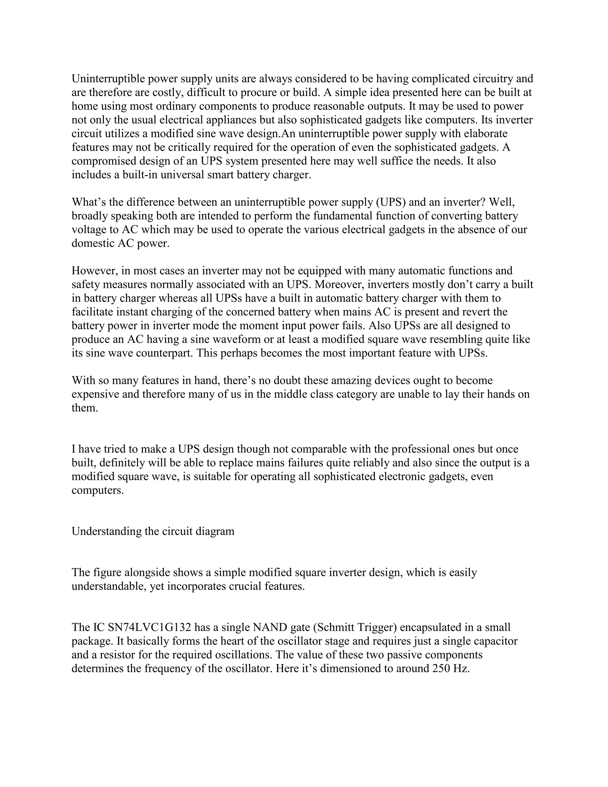
In large business environments where reliability is of great importance, a single huge UPS can
also be a single point of failure that can disrupt many other systems. To provide greater
reliability, multiple smaller UPS modules and batteries can be integrated together to provide
redundant power protection equivalent to one very large UPS. "N+1" means that if the load can
be supplied by N modules, the installation will contain N+1 modules. In this way, failure of one
module will not impact system operation.[9]
Multiple redundancy[edit]
Many computer servers offer the option of redundant power supplies, so that in the event of one
power supply failing, one or more other power supplies are able to power the load. This is a
critical point – each power supply must be able to power the entire server by itself.
Redundancy is further enhanced by plugging each power supply into a different circuit (i.e. to a
different circuit breaker).](https://image.slidesharecdn.com/theworkingprincipleofups-131110000152-phpapp02/75/The-working-principle-of-ups-5-2048.jpg)
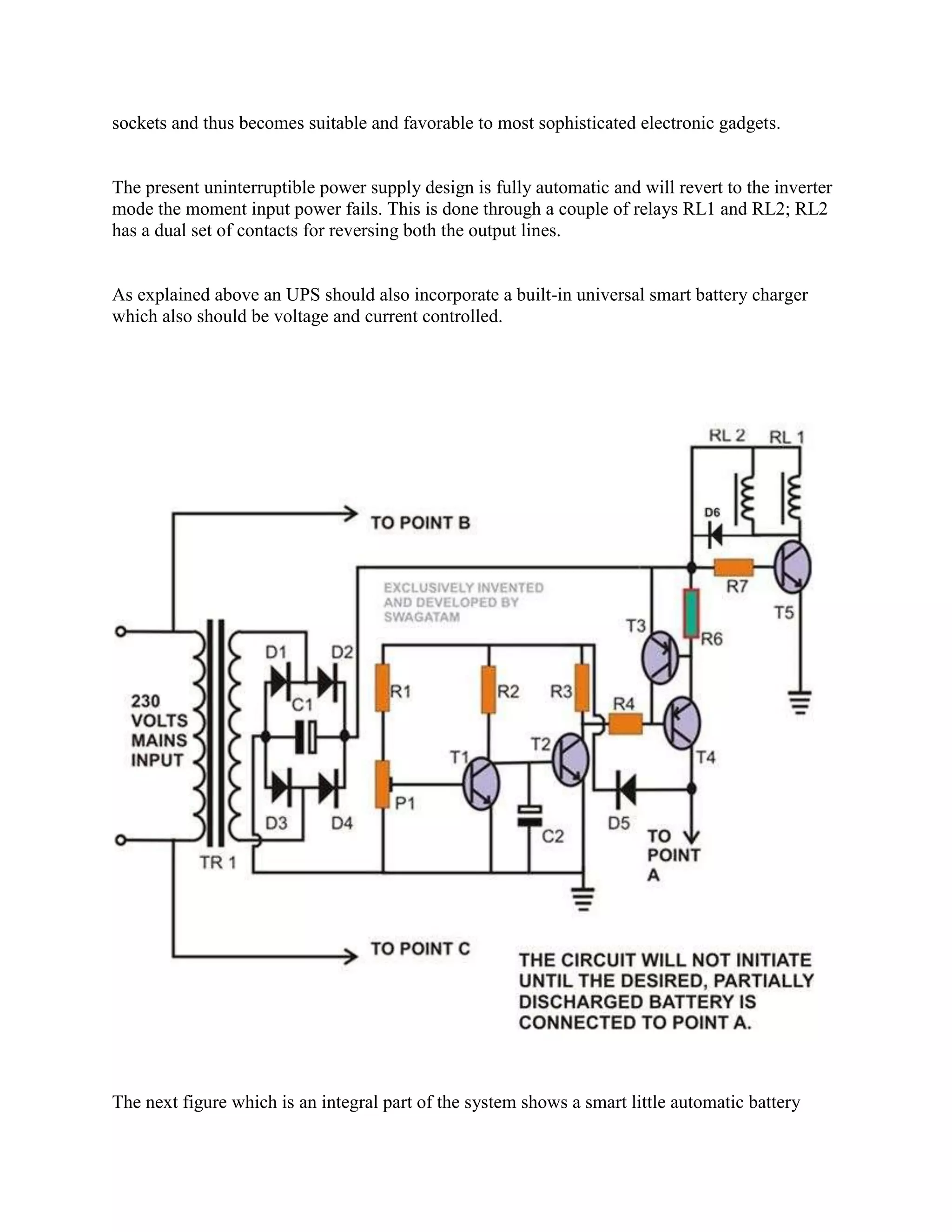
![Redundant protection can be extended further yet by connecting each power supply to its own
UPS. This provides double protection from both a power supply failure and a UPS failure, so that
continued operation is assured. This configuration is also referred to as 1+1 or 2N redundancy. If
the budget does not allow for two identical UPS units then it is common practice to plug one
power supply into mains power and the other into the UPS.[10]
Outdoor use[edit]
When a UPS system is placed outdoors, it should have some specific features that guarantee that
it can tolerate weather with no effect on performance. Factors such as temperature, humidity,
rain, and snow among others should be considered by the manufacturer when designing an
outdoor UPS system. Operating temperature ranges for outdoor UPS systems could be around
−40 °C to +55 °C.[citation needed]
Outdoor UPS systems can be pole, ground (pedestal), or host mounted. Outdoor environment
could mean extreme cold, in which case the outdoor UPS system should include a battery heater
mat, or extreme heat, in which case the outdoor UPS system should include a fan system or an
air conditioning system.
Internal systems[edit]
UPS systems can be designed to be placed inside a computer chassis. There are two types of
internal UPS. The first type is a miniaturized regular UPS that is made small enough to fit into a
5.25-inch CD-ROM slot bay of a regular computer chassis. The other type are re-engineered
switching power supplies that utilize dual AC or DC power sources as inputs and have built-in
switching control units.
Most of us take the mains ac supply for granted and use it almost casually without giving the
slightest thought to its inherent shortcomings and the danger posed to sophisticated and sensitive
electronic instruments/equipments. For ordinary household appliances such as incandencent
lamps, tubes, fans, TV and fridge, the mains ac supply does not make much difference, but when
used for computers, medical equipments and telecommunica¬tion systems, a clean, stable
interruption free power supply is of the utmost importance. Of the myriad of devices, processes](https://image.slidesharecdn.com/theworkingprincipleofups-131110000152-phpapp02/75/The-working-principle-of-ups-6-2048.jpg)


![Qcl 14-v3 [flowcharts]-[banasthali university]_[devanshi agarwal]](https://cdn.slidesharecdn.com/ss_thumbnails/qcl-14-v3flowchartsbanasthaliuniversitydevanshiagarwal-150115005231-conversion-gate02-thumbnail.jpg?width=640&height=640&fit=bounds)