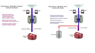
Power Factor
Improvement
Presentation by Rishab
25634
Power Factor
For a DC circuit the power is P=VI, and this relationship also holds for the instantaneous
power in an AC circuit. However, the average power in an AC circuit expressed in terms
of the rms voltage and current is
where φ is the phase angle between the voltage and current. The
additional term is called the power factor
From the phasor diagram for AC impedance, it can be seen that
the power factor is R/Z. For a purely resistive AC circuit, R=Z
and the power factor = 1.
Analogy
Power Factor should be close to unity.
• kW is the Working Power ( Real
Power) – Performs useful work
• kVAR (Kilo Volt Ampere Reactive) –
Reactive Power – To produce
magnetic flux
• kVA is Apparent Power – Vectorial
Summation of kVAR and kW
Relation of Power Factor Improvement
and Energy Conservation
What causes a low Power Factor?
 𝑃𝑜𝑤𝑒𝑟 𝐹𝑎𝑐𝑡𝑜𝑟, 𝐶𝑜𝑠 ∅ =
𝑘𝑊 (𝑅𝑒𝑎𝑙 𝑃𝑜𝑤𝑒𝑟)
𝑘𝑉𝐴 (𝑇𝑜𝑡𝑎𝑙 𝑃𝑜𝑤𝑒𝑟)
 Low power Factor results when kW is small in relation to kVA.
 Inductive Loads (Transformers, Induction motors, Induction generators ,etc.)
cause large KVAR in the system.
Reactive power (KVAR) required by inductive loads increases the amount of
apparent power (KVA) in distribution system. This increase in reactive and
apparent power results in a larger angle measured between kW and kVA. As ∅
increases, cos ∅ (or power factor) decreases.
Reasons to improve Power Factor:-
 Lower utility bills. By raising your power factor, we use less kVAR. This results
in less kW, which equates to savings from the utility.
 Increased voltage level and cooler, more efficient motors:-
 Reduces loading on transformers:-
For example, a 1,000 kVA transformer with an 80% power factor provides 800 kW (600 kVAR)
of power to the main bus. By increasing the power factor to 90%, more kW can be supplied
for the same amount of KVA
raising power factor, minimizes these voltage drops
along feeder cables and avoid related problems. Motors
will run cooler and be more efficient, with a slight
increase in capacity and starting torque.
1000 𝑘𝑉𝐴 = (800 𝑘𝑊)2+ (𝑥 𝑘𝑉𝐴𝑅)2 , ∴ 𝑥 𝑘𝑉𝐴𝑅 = 600
1000 𝑘𝑉𝐴 = (900 𝑘𝑊)2+ (𝑥 𝑘𝑉𝐴𝑅)2 , ∴ 𝑥 𝑘𝑉𝐴𝑅 = 436
Methods of Improving Power Factor
 Sources of Reactive Power increase power factor: -
􀂉 Capacitors
􀂉 Synchronous generators (utility and emergency)
􀂉 Synchronous motors
To increase power factor add capacitors to the system.
Working Power
Capacitance
Reactance
Capacitors store kVARS and release energy opposing the
reactive energy caused by the inductor.
Conclusion
 PF is the ratio of Active Power (kW)) to the Apparent Power (kVA).
 More the reactive power, less is the power factor
 Power factor can be improved by locally providing required Reactive power
References
 https://www.slideshare.net/_fahad_shaikh/power-factorr
 https://www.slideshare.net/tbmeng/power-factor-improvement-45696305
 http://edistoelectric.com/understanding-power-factor-and-why-its-important
 http://hyperphysics.phy-astr.gsu.edu/hbase/electric/powfac.html

PowerFactorImprovement.pptx

  • 1.
  • 2.
    Power Factor For aDC circuit the power is P=VI, and this relationship also holds for the instantaneous power in an AC circuit. However, the average power in an AC circuit expressed in terms of the rms voltage and current is where φ is the phase angle between the voltage and current. The additional term is called the power factor From the phasor diagram for AC impedance, it can be seen that the power factor is R/Z. For a purely resistive AC circuit, R=Z and the power factor = 1.
  • 3.
    Analogy Power Factor shouldbe close to unity. • kW is the Working Power ( Real Power) – Performs useful work • kVAR (Kilo Volt Ampere Reactive) – Reactive Power – To produce magnetic flux • kVA is Apparent Power – Vectorial Summation of kVAR and kW
  • 4.
    Relation of PowerFactor Improvement and Energy Conservation
  • 5.
    What causes alow Power Factor?  𝑃𝑜𝑤𝑒𝑟 𝐹𝑎𝑐𝑡𝑜𝑟, 𝐶𝑜𝑠 ∅ = 𝑘𝑊 (𝑅𝑒𝑎𝑙 𝑃𝑜𝑤𝑒𝑟) 𝑘𝑉𝐴 (𝑇𝑜𝑡𝑎𝑙 𝑃𝑜𝑤𝑒𝑟)  Low power Factor results when kW is small in relation to kVA.  Inductive Loads (Transformers, Induction motors, Induction generators ,etc.) cause large KVAR in the system. Reactive power (KVAR) required by inductive loads increases the amount of apparent power (KVA) in distribution system. This increase in reactive and apparent power results in a larger angle measured between kW and kVA. As ∅ increases, cos ∅ (or power factor) decreases.
  • 6.
    Reasons to improvePower Factor:-  Lower utility bills. By raising your power factor, we use less kVAR. This results in less kW, which equates to savings from the utility.  Increased voltage level and cooler, more efficient motors:-  Reduces loading on transformers:- For example, a 1,000 kVA transformer with an 80% power factor provides 800 kW (600 kVAR) of power to the main bus. By increasing the power factor to 90%, more kW can be supplied for the same amount of KVA raising power factor, minimizes these voltage drops along feeder cables and avoid related problems. Motors will run cooler and be more efficient, with a slight increase in capacity and starting torque. 1000 𝑘𝑉𝐴 = (800 𝑘𝑊)2+ (𝑥 𝑘𝑉𝐴𝑅)2 , ∴ 𝑥 𝑘𝑉𝐴𝑅 = 600 1000 𝑘𝑉𝐴 = (900 𝑘𝑊)2+ (𝑥 𝑘𝑉𝐴𝑅)2 , ∴ 𝑥 𝑘𝑉𝐴𝑅 = 436
  • 7.
    Methods of ImprovingPower Factor  Sources of Reactive Power increase power factor: - 􀂉 Capacitors 􀂉 Synchronous generators (utility and emergency) 􀂉 Synchronous motors To increase power factor add capacitors to the system. Working Power Capacitance Reactance Capacitors store kVARS and release energy opposing the reactive energy caused by the inductor.
  • 9.
    Conclusion  PF isthe ratio of Active Power (kW)) to the Apparent Power (kVA).  More the reactive power, less is the power factor  Power factor can be improved by locally providing required Reactive power
  • 10.
    References  https://www.slideshare.net/_fahad_shaikh/power-factorr  https://www.slideshare.net/tbmeng/power-factor-improvement-45696305 http://edistoelectric.com/understanding-power-factor-and-why-its-important  http://hyperphysics.phy-astr.gsu.edu/hbase/electric/powfac.html