Download to read offline

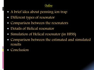
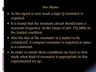
![Design parametersofHelical resonator
For a given shield diameter (D)
and resonant frequency (ƒ₀)
D = inside diameter of shield
d = mean diameter of the of turns
B = inside length of the shield
b = axial length of coil
do= diameter of conductor.
τ = pitch of winding
Qu=Unloaded resonant freq.
Units- Lengths are in inches and
frequency in MHz
•Design guidelines provided by Macalpine et al.[7]](https://image.slidesharecdn.com/9ea301a0-9200-4744-8fd6-33f94942320e-160613194634/85/Romiya_HR_presenetation-10-320.jpg)
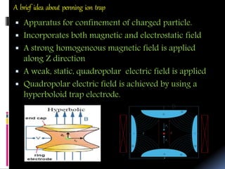
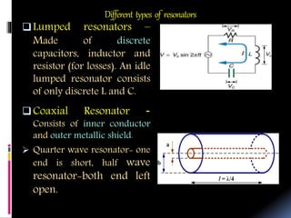
![Effective capacitance of the helical resonator
The helical resonator has an effective self capacitance (Ce) and capacitance
contributed from the ion trap and LNA which is roughly estimated to be the order
of (15-20) pF.
The resonator should resonate at the freq range of (60-70)MHz after a capacitive
loading of (15-20) pF. (Cl )
In order to calculate the resonant frequency under different capacitive loading,
the self capacitance of the resonator should be estimated first.
𝐶𝑐 = helical coil self-capacitance and 𝐶𝑠 = helical coil to the surrounding shield capacitance,
by empirical formula [using ref. 8]
10
10
27.0
08.01126.0.1
d
d
bd
b
CC
12
10
log
75.0
37.39.2
d
D
bC S
cCO CNC 1.3
1
.4
N
C
C S
SO
SOCO CCC 1.5
1,
11
1
.6
1
NC
CC
CC SO
CON
Ne
0f
CC
C
f
le
e
l
](https://image.slidesharecdn.com/9ea301a0-9200-4744-8fd6-33f94942320e-160613194634/85/Romiya_HR_presenetation-11-320.jpg)
![References
[1] K. Blaum, “High-accuracy mass spectrometry with stored ions,” Physics Report, Vol.
425, pp. 1-78, January 2006
[2] W. Shockley, Journal of Applied Physics, 9, 635 (1938)
[3] David M. Pozar, “Microwave Engineering”, 3nd Ed., Ch.6, Wiley, 2009.
[4] Saikat Sarkar, Ph.D Thesis: "Design and development of a compact helical
resonator for charged particle detection application" Submitted to The University of
Burdwan (2015)
[5] Peter Vizmuller, "RF Design Guide", Artech house,2nd Ed., pp. 237-240, 1995.
[6] V.S. Bagal, "Microwave Engineering", Technical publication Pune,1st Ed., pp. 2-19,
2009
[7] W.W.Macalpine and R.O.Schildknecht,”Coaxial resonator with helical inner
conductor,” Proc.IRE 47,2099(1959).
[8] K.Deng, Y.L.Sun, W.H.Yuan, Z.T.Xu, J.Zhang, Z.H.Lu and J.Luo,” A Modified model
of helical resonator with predictable loaded resonant Frequency and Q-factor,"
Rev.Sci.Instrum.85, 104706(2014).
[9] HFSS v10 User Guide - Anlage Research Group http://www
anlage.umd.edu/HFSSv10UserGuide.pdf
[10] RF & Microwave - ANSYS http://www
www.ansys.com/Products/Simulation+Technology/.../RF+&+Microwave](https://image.slidesharecdn.com/9ea301a0-9200-4744-8fd6-33f94942320e-160613194634/85/Romiya_HR_presenetation-18-320.jpg)


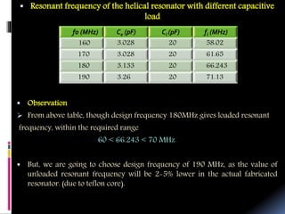
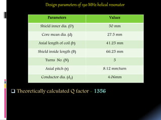
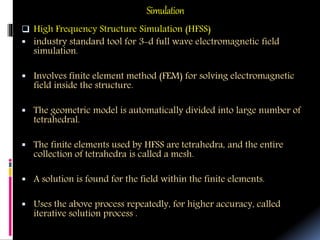
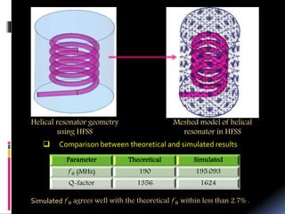
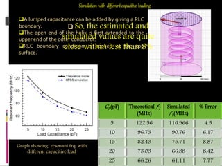
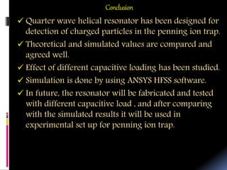
The document outlines the design of a helical resonator for use in a penning ion trap. It discusses different types of resonators and why a helical design is best. The document provides details on the design parameters and theoretical calculations for a 190 MHz helical resonator. Simulations of the resonator were performed using HFSS software, finding good agreement with theoretical resonant frequency and Q-factor values. The effect of different capacitive loads on resonant frequency was also studied through simulations. In conclusion, the helical resonator design is suitable for detection of charged particles in the penning ion trap application.


