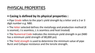
Casing Design
Casing Design
• Why Run Casing? Types of Casing Strings
• Classification of Casing
• Burst, Collapse and Tension Example
• Effect of Axial Tension on Collapse Strength
Casing Design
What is casing?
Casings are tubular goods run in a wellbore after
drilling the hole. They have various sizes to suit the
different hole sizes used in each section of the drilling
operation. Normally, casing will be cemented in a
wellbore.
Typically, casing is terminated on surface at the casing
hanger. Liners do not reach surface but are suspended
within the string of previous casing
Casing Design
• Why is Casing Design/Selection Important?
Casing is used for protection during all phases of
drilling & production.
Casing must be designed to withstand many
severe operating conditions.
The casing design must meet all potential
completion requirements
Casing Design
Why run casing?
1.To prevent the hole from caving in (keep it open due
to sloughing or swelling)
2.To protect fresh water zones from contamination.
3.To prevent water migration to producing formation.
4.To isolate porous formations with different
pressure regimes
5.To provide a production conduit & confine
production to the wellbore.
Casing Design - Why run casing, cont’d
6. To provide a foundation for the wellhead/BOP
7. To control pressures during drilling
8. To provide an acceptable environment for
subsurface equipment in producing wells
9. To enhance the probability of drilling to total depth
(TD) e.g., you need 14 ppg to control a lower zone,
but an upper zone will fracture at 12 lb/gal, What do you do?
CASING SCHEMATIC
Functions
1.Conductor (20”-30”) to protect loose, near surface formations and
enables
circulation of drilling fluid
2.Surface casing (13-3/8”- 20”) to provide blowout protection and prevent
loss circulation
3.Intermediate casing (9-5/8” - 16”) to isolate unstable hole section and
loss circulation, low pressure and production zones (often set in the transition
between normal to abnormal zone)
4.Production (4-1/2”-9-5/8”) to isolate production zone and contains
formation pressure in the event of tubing leaks
5.Liner (4-1/2” - 13-3/8”) to improve hydraulic performance during deep
drilling and to allow the use of larger tubing above the liner top
6.Tieback string to provide additional pressure integrity from the liner top
to the wellhead
PHYSICAL PROPERTIES
• Casing is defined by its physical properties :
• Pipe Grade refers to the pipe's yield strength by a letter and a 2 or 3
digit number e.g. N80.
• The letter selected defines the metallurgy and production method (K
is seamed, J is seamless, L is seamless and heat treated)
• The Numerical Code indicates the minimum yield strength in psi (N80
has a minimum yield strength of 80,000 psi).
• The Yield strength is used to determine the minimum value of pipe
Burst and Collapse resistance and the tensile strength.
CASING GRADES
Casing Designations
• When ordering casing, we should specify the following:
• Grade: refers to the yield strength and metallurgy of the tubular [N80,
K55, H40]
• Weight: refers to weight per unit length of tubular [47.0 lb/ft, 29.0 lb/ft]
• Size: refers to the outside diameter of tubular [13 3/8”, 9 5/8”]
• Connection: the coupling used to connect the tubulars [Buttress, VAM,
LT&C]
• Range: refers to average length of tubular joint [API: R1 = 16 to 25 ft,
R2 = 25 –34 ft and R3=35 – 45 ft]
CASING DESIGN
General Design Criteria
The final selection of casing (weight & grade) is based on an
assessment of the loadings to which a casing may be subjected.
Four primary factors to be considered in the final selection:
Collapse
Burst
Tension
Compression
CASING DESIGN
Secondary considerations in
casing design:
– Traxial stress
– Buckling
– Wear
– Internal and external corrosion
– Loading during pressure testing
– Loading during reciprocation
CASING DESIGN
Sources of Tubular Loads
 Tension
✓ String Weight
✓ Friction
 Compression
✓ Buoyancy
✓ Setting weight
✓ Reservoir compaction
 Burst and Collapse
✓ Fluid pressure
✓ Fluid expansion
 Bending
✓ Buckling
✓ Hole deviation
✓ Doglegs
CASING
DESIGN
(Process)
Casing Design-Burst Failure
• Internal Yield Pressure for Pipes & Couplings
• The casing will experience a net burst loading if the
internal radial load exceeds the external radial load.
Casing Design - Collapse Failure
 The casing will
experience a net collapse
loading if the external
radial load exceeds the
internal radial load.
 The greatest collapse
load on the casing will
occur if the casing is
evacuated (empty) for
any reason.
Casing Design - Collapse Failure
 For collapse design, we start at
the bottom of the string and
work our way up.
 Our design criteria will be based
on hydrostatic pressure resulting
from the mud density that will
be in the hole when the casing
string is run, prior to cementing.
Casing Design - Tension
The axial loads on the casing can be either tensile or
compressive, depending on the operating conditions.
CASING DESIGN
CASING DESIGN
CASING DESIGN

Casing Physical Properties,casing Grades and design .ppt

  • 1.
  • 2.
    Casing Design • WhyRun Casing? Types of Casing Strings • Classification of Casing • Burst, Collapse and Tension Example • Effect of Axial Tension on Collapse Strength
  • 3.
    Casing Design What iscasing? Casings are tubular goods run in a wellbore after drilling the hole. They have various sizes to suit the different hole sizes used in each section of the drilling operation. Normally, casing will be cemented in a wellbore. Typically, casing is terminated on surface at the casing hanger. Liners do not reach surface but are suspended within the string of previous casing
  • 4.
    Casing Design • Whyis Casing Design/Selection Important? Casing is used for protection during all phases of drilling & production. Casing must be designed to withstand many severe operating conditions. The casing design must meet all potential completion requirements
  • 5.
    Casing Design Why runcasing? 1.To prevent the hole from caving in (keep it open due to sloughing or swelling) 2.To protect fresh water zones from contamination. 3.To prevent water migration to producing formation. 4.To isolate porous formations with different pressure regimes 5.To provide a production conduit & confine production to the wellbore.
  • 6.
    Casing Design -Why run casing, cont’d 6. To provide a foundation for the wellhead/BOP 7. To control pressures during drilling 8. To provide an acceptable environment for subsurface equipment in producing wells 9. To enhance the probability of drilling to total depth (TD) e.g., you need 14 ppg to control a lower zone, but an upper zone will fracture at 12 lb/gal, What do you do?
  • 7.
    CASING SCHEMATIC Functions 1.Conductor (20”-30”)to protect loose, near surface formations and enables circulation of drilling fluid 2.Surface casing (13-3/8”- 20”) to provide blowout protection and prevent loss circulation 3.Intermediate casing (9-5/8” - 16”) to isolate unstable hole section and loss circulation, low pressure and production zones (often set in the transition between normal to abnormal zone) 4.Production (4-1/2”-9-5/8”) to isolate production zone and contains formation pressure in the event of tubing leaks 5.Liner (4-1/2” - 13-3/8”) to improve hydraulic performance during deep drilling and to allow the use of larger tubing above the liner top 6.Tieback string to provide additional pressure integrity from the liner top to the wellhead
  • 8.
    PHYSICAL PROPERTIES • Casingis defined by its physical properties : • Pipe Grade refers to the pipe's yield strength by a letter and a 2 or 3 digit number e.g. N80. • The letter selected defines the metallurgy and production method (K is seamed, J is seamless, L is seamless and heat treated) • The Numerical Code indicates the minimum yield strength in psi (N80 has a minimum yield strength of 80,000 psi). • The Yield strength is used to determine the minimum value of pipe Burst and Collapse resistance and the tensile strength.
  • 9.
  • 10.
    Casing Designations • Whenordering casing, we should specify the following: • Grade: refers to the yield strength and metallurgy of the tubular [N80, K55, H40] • Weight: refers to weight per unit length of tubular [47.0 lb/ft, 29.0 lb/ft] • Size: refers to the outside diameter of tubular [13 3/8”, 9 5/8”] • Connection: the coupling used to connect the tubulars [Buttress, VAM, LT&C] • Range: refers to average length of tubular joint [API: R1 = 16 to 25 ft, R2 = 25 –34 ft and R3=35 – 45 ft]
  • 11.
    CASING DESIGN General DesignCriteria The final selection of casing (weight & grade) is based on an assessment of the loadings to which a casing may be subjected. Four primary factors to be considered in the final selection: Collapse Burst Tension Compression
  • 12.
    CASING DESIGN Secondary considerationsin casing design: – Traxial stress – Buckling – Wear – Internal and external corrosion – Loading during pressure testing – Loading during reciprocation
  • 13.
    CASING DESIGN Sources ofTubular Loads  Tension ✓ String Weight ✓ Friction  Compression ✓ Buoyancy ✓ Setting weight ✓ Reservoir compaction  Burst and Collapse ✓ Fluid pressure ✓ Fluid expansion  Bending ✓ Buckling ✓ Hole deviation ✓ Doglegs
  • 14.
  • 15.
    Casing Design-Burst Failure •Internal Yield Pressure for Pipes & Couplings • The casing will experience a net burst loading if the internal radial load exceeds the external radial load.
  • 16.
    Casing Design -Collapse Failure  The casing will experience a net collapse loading if the external radial load exceeds the internal radial load.  The greatest collapse load on the casing will occur if the casing is evacuated (empty) for any reason.
  • 17.
    Casing Design -Collapse Failure  For collapse design, we start at the bottom of the string and work our way up.  Our design criteria will be based on hydrostatic pressure resulting from the mud density that will be in the hole when the casing string is run, prior to cementing.
  • 18.
    Casing Design -Tension The axial loads on the casing can be either tensile or compressive, depending on the operating conditions.
  • 19.
  • 20.
  • 21.