Testing and Validation of Thermoelectric Coolers

The first Air conditioners and refrigerators employed toxic or flammable gases such as Chloro Fluoro Carbons (CFC’s), Hydro Chloro Fluorocarbons (HCFC’s), Hydro Fluoro Carbons (HFC’s) and ammonia that could result in fatal accidents when they leaked into the atmosphere. In an automobile, the AC system increases fuel consumption of the vehicle, which uses around 4HP (i.e. 3 kW) of the engine's power. Most refrigerants used for AC system contribute to global warming, and may also destroy the ozone layer. CFC’s, HCFC’s, and HFC’s are poisonous greenhouse gases when they are leaked to the atmosphere and 100 gm of HFC’s destroy 0.5 tons of O3 molecules. In recent years, demand for small size active cooling equipment has increased which includes TEC and water cooled heat sink. While on the other hand the passive cooling system includes heat sink and fan which is not effective enough to cope with task of cooling various electronic components. The active cooling system using TEC can be used where precise control of temperature is required. The energy conversion process which is carried out by active cooling system to absorb the heat from the surface to be cooled and reject that heat to the surrounding. Our project objective is testing and validation of TEC1-12706 and evaluating its capacity, limitations and performance to be used to produce cooling effect in R&AC system. Authors are presenting performance curve enabling the user to design the optimum number of thermoelectric module (TEM) for any required cooling system. In order to find out the capacity of single TEC we have made a prototype in which the existing refrigerants are replaced by newly emerging TEC which works on Peltier effect in AC system. TEC can be used as a generator to generate electricity by applying reverse engineering.

Recommended
Recommended
More Related Content
What's hot
What's hot (19)
Viewers also liked
Viewers also liked (20)
Similar to Testing and Validation of Thermoelectric Coolers
Similar to Testing and Validation of Thermoelectric Coolers (20)
Recently uploaded
Recently uploaded (20)
Testing and Validation of Thermoelectric Coolers
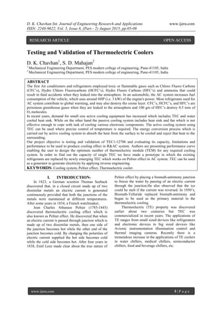
- 1. D. K. Chavhan Int. Journal of Engineering Research and Applications www.ijera.com ISSN: 2248-9622, Vol. 5, Issue 8, (Part - 2) August 2015, pp.05-09 www.ijera.com 5 | P a g e Testing and Validation of Thermoelectric Coolers D. K. Chavhan1 , S. D. Mahajan2 1 Mechanical Engineering Department, PES modern college of engineering, Pune-41105, India 2 Mechanical Engineering Department, PES modern college of engineering, Pune-41105, India ABSTRACT The first Air conditioners and refrigerators employed toxic or flammable gases such as Chloro Fluoro Carbons (CFC’s), Hydro Chloro Fluorocarbons (HCFC’s), Hydro Fluoro Carbons (HFC’s) and ammonia that could result in fatal accidents when they leaked into the atmosphere. In an automobile, the AC system increases fuel consumption of the vehicle, which uses around 4HP (i.e. 3 kW) of the engine's power. Most refrigerants used for AC system contribute to global warming, and may also destroy the ozone layer. CFC’s, HCFC’s, and HFC’s are poisonous greenhouse gases when they are leaked to the atmosphere and 100 gm of HFC’s destroy 0.5 tons of O3 molecules. In recent years, demand for small size active cooling equipment has increased which includes TEC and water cooled heat sink. While on the other hand the passive cooling system includes heat sink and fan which is not effective enough to cope with task of cooling various electronic components. The active cooling system using TEC can be used where precise control of temperature is required. The energy conversion process which is carried out by active cooling system to absorb the heat from the surface to be cooled and reject that heat to the surrounding. Our project objective is testing and validation of TEC1-12706 and evaluating its capacity, limitations and performance to be used to produce cooling effect in R&AC system. Authors are presenting performance curve enabling the user to design the optimum number of thermoelectric module (TEM) for any required cooling system. In order to find out the capacity of single TEC we have made a prototype in which the existing refrigerants are replaced by newly emerging TEC which works on Peltier effect in AC system. TEC can be used as a generator to generate electricity by applying reverse engineering. KEYWORDS- Cooling system, Peltier effect, Thermoelectric cooler. I. INTRODUCTION- In 1823, a German scientist Thomas Seeback discovered that, in a closed circuit made up of two dissimilar metals an electric current is generated continuously provided that both the junctions of the metals were maintained at different temperatures. After some years in 1834, a French watchmaker, Jean Charles Athanase Peltier (1785-1845) discovered thermoelectric cooling effect which is also known as Peltier effect. He discovered that when an electric current is passed through junction which is made up of two dissimilar metals, then one side of the junction becomes hot while the other end of the junction becomes cold. By changing the polarities of electric current supplied the hot side becomes cold while the cold side becomes hot. After four years in 1838, Emil Lenz made clear about the true nature of Peltier effect by placing a bismuth-antimony junction to freeze the water by passing of an electric current through the junction.He also observed that the ice could be melt if the current was reversed. In 1950’s, Bismuth-Telluride replaced bismuth-antimony and began to be used as the primary material in the thermoelectric cooling. Thermoelectric (TE) property was discovered earlier about two centuries but TEC was commercialized in recent years. The applications of TE ranges from small sized devices like refrigerators and electronic devices to big sized devices like Avionic instrumentation illumination control and thermal imaging cameras. Recently there is a tremendous increase in the applications of TE coolers in water chillers, medical chillers, semiconductor chillers, food and beverage chillers, etc. RESEARCH ARTICLE OPEN ACCESS
- 2. D. K. Chavhan Int. Journal of Engineering Research and Applications www.ijera.com ISSN: 2248-9622, Vol. 5, Issue 8, (Part - 2) August 2015, pp.05-09 www.ijera.com 6 | P a g e TEC1-12706:- Fig.1. Schematic Diagram of a Thermoelectric Cooler (TEC) Ceramic Material: Alumina (Al2O3), white Solder Construction: 138ºC, Bismuth Tin (BiSn) Marking is present on the cold side surface of TEC. In following size table all dimension in mm Size Table:- A B C 40 40 3.9 Performance Table:- Hot Side Temperature (ºC) 25ºC 50ºC Qmax (Watts) 50 57 Delta Tmax (ºC) 66 75 Imax (Amps) 6.4 6.4 Vmax (Volts) 14.4 16.4 Module Resistance (Ohms) 1.98 2.30 Table no. 2 Performance Table:- Fig. 2 Working principle of TEC module
- 3. D. K. Chavhan Int. Journal of Engineering Research and Applications www.ijera.com ISSN: 2248-9622, Vol. 5, Issue 8, (Part - 2) August 2015, pp.05-09 www.ijera.com 7 | P a g e TEC works on the principle of Peltier effect, when a DC is supplied from a 12V battery to TEC module then, heat is absorbed at one junction and dissipated at the other junction. Depending on the direction of applied DC power source and the relative Seeback coefficient of the two materials, the direction of the heat flow is regulated. TEC can be used either for heating or for cooling, while the main application is cooling. TEC module is a solid-state active heat pump which contains number of p- and n- type semi-conductor which are coupled in series and sandwiched between two thermally conductive and electrically insulated ceramic substrate. The main advantages of a TEC compared to a vapor- compression refrigerator are its lack of moving parts or circulating refrigerants, flexible shape, invulnerability to potential leaks and its smaller size. The "hot" side is attached to a water cooled heat sink so that it remains at ambient temperature, while the “cold” side goes below room temperature. Multiple coolers can be cascaded together for lower temperature for some applications. There are various thermoelectric materials which include Lead Telluride (Pb-Te), Silicon Germanium (Si-Ge), Bismuth-Antimony (Bi-Sb) and Bismuth Telluride (Bi-Te) alloys that may be used according to the situations. Conventional R&AC system uses refrigerant to carry the heat from refrigerated space while TEC uses electrons rather than refrigerant as a carrier of heat. TEC is the emerging green R&AC technology which can be used to couple with Solar PV cell generated DC power, which makes them complete environmental friendly. II. EXPERIMENTAL PROCEDURE - 2.1 Construction- Fig.3 Construction of TEC Model Whole setup consists of: Two water cooled heat sink Two TEC1-12706 Two internal fins Blower(12V) Pump(12V, 3A, 100psi) Radiator + Fan(12V) Pipes & ducts Battery(12V, 45A) Silicon paste. PT-100 temperature sensors(K-type) Anemometer For testing and validation of TEC1-12706 authors have developed and designed TEC model which is used for cooling the internal fins. For better design convenience, two TEC are sandwich between internal fins and water cooled heat sinks. Cold side of TEC is placed on internal fins while the hot side is attached to water cooled heat sinks. For better heat conduction silicon paste is applied on both surfaces of TEC while sandwiching. The assembly is made closed circuit by joining TEC model with radiator by using pump. 2.2 Working- From the DC power source current is passed to both the TEC’s, as a result one side of TEC becomes hot and other side becomes cold. The water cooled heat sinks extract heat from the hot side of two TEC and supplies hot water to the radiator and this hot
- 4. D. K. Chavhan Int. Journal of Engineering Research and Applications www.ijera.com ISSN: 2248-9622, Vol. 5, Issue 8, (Part - 2) August 2015, pp.05-09 www.ijera.com 8 | P a g e water coming from both the heat sinks are cooled in the radiator with the help of fan, and it again recirculates the cold water to both the heat sinks with the help of pump. III. CALCULATION: 3.1 Theoretically Mass flow Rate - Sensible heat gained by air: Q = mf Cp ∆T………………………………………… (1) Forced convection heat transfer: Q = h A (Tm - Tf) ……………………………….……. (2) Equating equation (1) and (2), authors get mass flow rate of air (mf) mf = 0.002825 m3 /s 3.2 Practically found Mass Flow Rate - The mass flow rate of air can also be calculated by: mf = A v …………………………………………(3) mf = 0.00182 m3 /s Fig.4 Graph of Time vs. Temperature of fin surface IV. CONCLUSION AND RESULT- In this way, the authors calculated theoretical mass flow rate of air (mf = 0.002825m3 /s) and actual mass flow rate of air (mf = 0.00182m3 /s) for two TEC’s. With the help of two TEC’s the surface temperature of internal fins which was initially at 30°C is brought down to -7°C in 9 minutes. And also the temperature of air coming from blower at 30°C is reduced upto 18°C at saturated condition. So it is concluded that the TEC can be used for various applications in R&AC system, food and beverage chillers, medical chillers, semiconductor chillers and water chillers. Also there are various advantages of TEC, such as small and lightweight, reliable, free from noise and vibration, portable, precise temperature control, environmental friendly, no moving parts, localize cooling, fast temperature response, nearly infinite life(2,00,000 hrs.) Hence TEC can become the best alternative to the refrigerants used in conventional R&AC system. So the result from this paper can be used for further research and study in the development of application. V. ACKNOWLEDGEMENTS- The project has been carried out in Modern College of Engineering Pune, India. Authors are very thankful to H.O.D (Mechanical dept.), project guide and other faculties of college who helped us for making project successful. Authors are duly acknowledged to the Director, IJERA, for his kind support and permitting to publish the results derived from the project. REFERENCE- [1] Manoj S. Raut, “Thermoelectric Air Cooling For Cars”, International Journal of Engineering Science and Technology, Vol. 4 No.05 (2012), ISSN: 0975-5462. [2] Simon Lineykin, Sam Ben-Yaakov, “User- friendly and intuitive graphical approach to the design of thermoelectric cooling systems”, International Journal of Refrigeration 30 (2007) 798-804. [3] Manoj Kumar Rawat, Himadri Chattopadhyay, Subhasis Neogi, “A review on developments of thermoelectric refrigeration and air conditioning systems: a novelpotential green refrigeration and air
- 5. D. K. Chavhan Int. Journal of Engineering Research and Applications www.ijera.com ISSN: 2248-9622, Vol. 5, Issue 8, (Part - 2) August 2015, pp.05-09 www.ijera.com 9 | P a g e conditioningtechnology”, International Journal of Emerging Technology and Advanced Engineering, Volume 3, Special Issue 3: ICERTSD (2013), ISSN 2250-2459. NOMENCLATURE- A -Area of fins surface (m2 ) AC -Air conditioner CFC -ChloroFluoro Carbons Cp -Heat capacity at constant pressure (J kg/K) DC -Direct Current (A) H -Convective heat transfer coefficient (W/m2 K) HCFC -Hydro ChloroFluorocarbons HFC -HydroFluoro Carbons HP -Horse power Imax -Maximum current (Amps) mf -Mass flow rate (kg/s) Q -Net rate of heat transfer (W) Qmax -Maximum power (Watts) R&AC -Refrigeration and Air Conditioning TEC -Thermoelectric cooler TEM -Thermoelectric Module TE -Thermoelectric Tm -Mean temperature of inlet and outlet air (K) Tf -Fins temperature (K) ΔT -Temperature difference (o C) Vmax -Maximum voltage (V) v -Velocity of air (m/s)