SlideShare a Scribd company logo
1 of 8
Download to read offline
T. Satish Babu et al Int. Journal of Engineering Research and Applications www.ijera.com
ISSN : 2248-9622, Vol. 4, Issue 4( Version 4), April 2014, pp.09-16
www.ijera.com 9 | P a g e
Stability Enhancement of Power System by Controlling Hvdc
Power Flow through the Same Ac Transmission Line
P. Upendra Kumar*
, T. Satish Babu**
, P. Divakar**
, T. Ravi Teja Kumar**
, G. Rama Raju**
*Associate Professor, Dept Of Eee, Lendi Institute Of Engineering And Technology, Vizianagaram, A.P., India.
**Ug Students, Dept Of Eee, Lendi Institute Of Engineering And Technology, Vizianagaram, A.P., India.
ABSTRACT
Long extra high voltage (EHV) ac lines cannot be loaded to their thermal limits in order to keep sufficient
margin against transient instability. With the scheme proposed in this paper, it is possible to load these lines
very close to their thermal limits. The conductors are allowed to carry usual ac along with dc superimposed on
it. The added dc power flow does not cause any transient instability.
This paper presents the feasibility of converting a double circuit ac line into composite ac–dc power
transmission line to get the advantages of parallel ac–dc transmission to improve stability and damping out
oscillations. Simulation and experimental studies are carried out for the coordinated control as well as
independent control of ac and dc power transmissions. No alterations of conductors, insulator strings, and
towers of the original line are needed. Substantial gain in the loadability of the line is obtained. Master current
controller senses ac current and regulates the dc current orders for converters online such that conductor current
never exceeds its thermal limit.
The present paper is implemented by using MATLAB/SIMULINK.
Key word: Extra high voltage (EHV) transmission, flexible ac transmission system (FACTS), simultaneous
ac–dc power transmission.
I. INTRODUCTION
In recent years, environmental, right-of-
way, and cost concerns have delayed the construction
of a new transmission line, while demand of electric
power has shown steady but geographically uneven
growth. The power is often available at locations not
close to the growing load centers but at remote
locations. These locations are largely determined by
regulatory policies, environmental acceptability, and
the cost of available energy. The wheeling of this
available energy through existing long ac lines to
load centers has a certain upper limit due to stability
considerations. Thus, these lines are not loaded to
their thermal limit to keep sufficient margin against
transient instability. The present situation demands
the review of traditional power transmission theory
and practice, on the basis of new concepts that allow
full utilization of existing transmission facilities
without decreasing system availability and security.
The flexible ac transmission system (FACTS)
concepts, based on applying state-of-the-art power
electronic technology to existing ac transmission
system, improve stability to achieve power
transmission close to its thermal limit. Another way
to achieve the same goal is simultaneous ac–dc
power transmission in which the conductors are
allowed to carry superimposed dc current along with
ac current. Ac and dc power flow independently, and
the added dc power flow does not cause any transient
instability. The authors of this paper have earlier
shown that extra high voltage (EHV) ac line may be
loaded to a very high level by using it for
simultaneous ac–dc power transmission as reported
in references. The basic proof justifying the
simultaneous ac–dc power transmission is explained
in reference. In the above references, simultaneous
ac–dc power transmission was first proposed through
a single circuit ac transmission line. In these
proposals Mono-polar dc transmission with ground as
return path was used. There were certain limitations
due to use of ground as return path. Moreover, the
instantaneous value of each conductor voltage with
respect to ground becomes higher by the amount of
the dc voltage, and more discs are to be added in each
insulator string to withstand this increased voltage.
However, there was no change in the conductor
separation distance, as the line-to-line voltage
remains unchanged. In this paper, the feasibility
study of conversion of a double circuit ac line to
composite ac–dc line without altering the original
line conductors, tower structures, and insulator
strings has been presented. In this scheme, the dc
power flow is point to point bipolar transmission
system. Suggested the conversion of ac line to dc line
for substantial power upgrading of existing ac line.
However, this would require major changes in the
tower structure as well as replacement of ac insulator
strings with high creepage dc insulators. The novelty
of our proposed scheme is that the power transfer
enhancement is achieved without any alteration in the
RESEARCH ARTICLE OPEN ACCESS
T. Satish Babu et al Int. Journal of Engineering Research and Applications www.ijera.com
ISSN : 2248-9622, Vol. 4, Issue 4( Version 4), April 2014, pp.09-16
www.ijera.com 10 | P a g e
existing EHV ac line. The main object is to gain the
advantage of parallel ac–dc transmission and to load
the line close to its thermal limit.
II. SIMULTANEOUS AC – DC POWER
TRANSMISSION
2.1 Basic concept
Fig 2.1: Basic Scheme for composite AC-DC
transmission
Fig 2.1 depicts the basic scheme for
simultaneous ac–dc power flow through a double
circuit ac transmission line. The DC power is
obtained through line commutated 12- pulse rectifier
bridge used in conventional HVDC and injected to
the neutral point of the zigzag connected secondary
of sending end transformer and is reconverted to AC
again by the conventional line commutated 12-pulse
bridge inverter at the receiving end. The inverter
bridge is again connected to the neutral of zig-zag
connected winding of the receiving end transformer.
The double circuit AC transmission line carriers both
three-phase AC and DC power. Each conductor of
each line carries one third of the total DC current
along with ac current. Resistance being equal in all
the three phases of secondary winding of zig-zag
transformer as well as the three conductors of the
line, the DC current is equally divided among all the
three phases. The three conductors of the second line
provide return path for the Dc current. Zig-zag
connected winding is used at both ends to avoid
saturation of transformer due to DC current. Two
fluxes produced by the DC current (Id/3) flowing
through each of a winding in each limb of the core of
a zig-zag transformer are equal in magnitude and
opposite in direction. So the net DC flux at any
instant of time becomes zero in each limb of the core.
Thus, the DC saturation of the core is avoided. A
high value of reactor X d is used to reduce harmonics
in DC current. In the absence of zero sequence and
third harmonics or its multiple harmonic voltages,
under normal operating conditions, the AC current
flow through each transmission line will be restricted
between the zig-zag connected windings and the
three conductors of the transmission line. Even the
presence of these components of voltages may only
be able to produce negligible current through the
ground due to high value of X d. Assuming the usual
constant current control of rectifier and constant
extinction angle control of inverter, the equivalent
circuit of the scheme under normal steady-state
operating condition is given in Fig. 2.2.
Fig. 2.2 Equivalent circuit
The dotted lines in the figure show the path of AC
return current only. The second transmission line
carries the return DC current Id , and each conductor
of the line carries Id/3 along with the AC current per
phase. Vdro and Vdio are the maximum values of
rectifier and inverter side DC voltages and are equal
to (3 ) times converter AC input line-to-line
voltage. R, L, and C are the line parameters per phase
of each line. Rcr, Rci are commutating resistances, and
α, are firing and extinction angles of rectifier and
inverter, respectively.
Neglecting the resistive drops in the line conductors
and transformer windings due to DC current,
expressions for AC voltage and current, and for
active and reactive powers in terms of A, B, C, and D
parameters of each line may be written as
Es=AER+BIR (2.1)
IS=CER+DIR (2.2)
PS+JQS=-ESE*R/B*+D*E2
R/B* (2.3)
PR+JQR=-E*SER/B*-A*E2
R/B* (2.4)
Neglecting AC resistive drop in the line and
transformer, the DC power Pdr and Pdi of each
rectifier and inverter may be expressed as
Pdr= Vdr Id (2.5)
Pdi= Vdi Id (2.6)
Reactive powers required by the converters are
Qdr= Pdr r (2.7)
Qdi= Pdi I (2.8)
r= ( α + α+ µr))/2 (2.9)
i= ( α + α+ µi))/2 (2.10)
μr and μi are commutation angles of inverter and
rectifier, respectively, and total active and reactive
powers at the two ends areTransmission loss for each
line is
PL= (PS+Pdr)-(PR+Pdi) (2.11)
T. Satish Babu et al Int. Journal of Engineering Research and Applications www.ijera.com
ISSN : 2248-9622, Vol. 4, Issue 4( Version 4), April 2014, pp.09-16
www.ijera.com 11 | P a g e
Ia being the rms AC current per conductor at any
point of the line, the total rms current per conductor
becomes
I= [Ia
2
+(Id/3)2
]1/2
(2.12)
Power loss for each line PL≈ 3I2
R (2.13)
The net current I in any conductor is
offseted from zero. In case of a fault in the
transmission system, gate signals to all the SCRs are
blocked and that to the bypass SCRs are released to
protect rectifier and inverter bridges. The current in
any conductor is no more offseted. Circuit breakers
(CBs) are then tripped at both ends to isolate the
faulty line. CBs connected at the two ends of
transmission line interrupt current at natural current
zeroes, and no special DC CB is required. Now,
allowing the net current through the conductor equal
to its thermal limit (Ith).
I=[Ia
2
+(Id/3)2
]1/2
(2.14)
Let Vph be per-phase rms voltage of
original ac line. Let Vph also Va be the per-phase
voltage of ac component of composite AC-DC line
with dc Vd voltage superimposed on it. As insulators
remain unchanged, the peak voltage in both cases
should be equal
Vmax = Vph = Vd+ Va (2.15)
Electric field produced by any conductor
possesses a DC component superimpose on it a
sinusoidally varying AC component. However, the
instantaneous electric field polarity changes its sign
twice in a cycle if (Vd/Va < 2) is insured.
Therefore, higher creep age distance requirement for
insulator discs used for HVDC lines are not required.
Each conductor is to be insulated for Vmax, but the
line-to line voltage has no DC component and VLL
max = 6Va. Therefore, conductor-to-conductor
separation distance of each line is determined only by
rated AC voltage of the line. Allowing maximum
permissible voltage offset such that the composite
voltage wave just touches zero in each every cycle;
Vd= Vph/ and Va = Vph/ (2.16)
The total power transfer through the double circuit
line before conversion is as follows:
P’total ≈ 3 Vph
2
1/X (2.17)
Where X is the transfer reactance per phase of the
double circuit line, 1 and is the power angle between
the voltages at the two ends. To keep sufficient
stability margin, 1 is generally kept low for long
lines and seldom exceeds 30o. With the increasing
length of line, the load ability of the line is decreased.
An approximate value of 1 may be computed from
the load ability curve by knowing the values of surge
impedance loading (SIL) and transfer reactance X of
the line.
P’total = 2.M.SIL (2.18)
Where M is the multiplying factor and its
magnitude decreases with the length of line. The
value of M can be obtained from the load ability
curve.
The total power was transfer through the composite
line.
Ptotal = Pac + Pdc = 3Va
2
2/X+2VdId (2.19)
The power angle 2 between the AC
voltages at the two ends of the composite line may be
increased to a high value due to fast controllability of
DC component of power. For a constant value of
total power, Pac may be modulated by fast control of
the current controller of DC power converters.
Approximate value of AC current per phase per
circuit of the double circuit line may be computed as
Ia= V( /2)/X (2.20)
The rectifier DC current order is adjusted online as
Id=3 Ith
*2
-Ia
*2
(2.21)
Preliminary qualitative analysis suggests
that commonly used techniques in HVDC/AC system
may be adopted for the purpose of the design of
protective scheme, filter, and instrumentation
network to be used with the composite line for
simultaneous AC-DC power flow. In case of a fault
in the transmission system, gate signals to all the
SCRs are blocked and that to the bypass SCRs are
released to protect rectifier and inverter bridges. CBs
are then tripped at both ends to isolate the complete
system. A surge diverter connected between the zig-
zag neutral and the ground protects the converter
bridge against any over voltage.
2.2 Economic consideration
To get the advantages of parallel AC–DC
transmission in order to improve stability and
damping oscillations, the conversion of a double
circuit AC line for simultaneous AC–DC power flow
has been considered such that no alterations of
conductor, insulator string and tower structure of the
original line are required. The optimum values of AC
phase and DC voltages of the converted line are 1/2
and 1/√2 times the phase voltage before conversion,
respectively. The cost of transmission line includes
the investment and operational costs. The investment
includes costs of Right of Way (RoW), transmission
tower, conductors, insulators, labour and terminal
equipments. The operational costs include mainly the
cost of losses. Additional costs of compensation and
its terminal equipments also influences the AC line
cost. DC transmission does not require compensation
but the terminal equipment costs are increased due to
the presence of converters and filters. Replacement of
Y-connected transformer in simultaneous AC–DC
T. Satish Babu et al Int. Journal of Engineering Research and Applications www.ijera.com
ISSN : 2248-9622, Vol. 4, Issue 4( Version 4), April 2014, pp.09-16
www.ijera.com 12 | P a g e
power transmission with zig-zag transformer is not
likely to increase the cost, because it transfers only
25% of total power by transformer action. Also, the
AC voltage reduces to 50% of the original AC
voltage. However, the neutral point of this
transformer needs insulation to withstand DC
voltage. The load ability is observed to get doubled
or even more with the simultaneous AC–DC power
flow for a line with length of 500 km or longer.
When an existing AC line is converted to
simultaneous AC–DC line, instead of adding separate
parallel DC, the additional investment on new DC
line and on AC line compensations are saved.
III.MODELLING OF COMPOSITE AC-DC SYSTEM
Fig 3: Simulink Model of Simultaneous AC-DC Transmission
IV.PROPOSED APPLICATIONS
1. Long EHV ac lines can not be loaded to their
thermal limit to keep sufficient margin against
transient instability and to keep voltage
regulation within allowable limit, the
simultaneous power flow does not imposed any
extra burden on stability of the system, rather it
improves the stability. The resistive drop due to
dc current being very small in comparison to
impedance drop due to ac current, there is also
no appreciable change in voltage regulation due
to superimposed dc current.
2. Therefore one possible application of
simultaneous ac-dc transmission is to load the
line close to its thermal limit by transmitting
additional dc power. Figure3 shows the variation
of Pt/Pac for changing values of k and x at unity
power factor. However, it is to be noted that
additional conductor insulation is to be provided
due to insertion of dc.
3. Necessity of additional dc power transmission
will be experienced maximum during peak load
period which is characterized with lower than
rate voltage. If dc power is injected during the
peak loading period only with V d being in the
range of 5% to 10% of E ph, the same
transmission line without having any enhanced
insulation level may be allowed to be used For
10.2% more power may be transmitted.
4. By adding a few more discs in insulator strings
of each phase conductor with appropriate
modifications in cross-arms of towers insulation
level between phase to ground may be increased
to a high value, which permits proportional
increase in Emax, Therefore higher value of Vd
may be used to increase dc and total power flow
through the line. This modification in the exiting
ac lines is justified due to high cost of a separate
HVDC line.
5. With the very fast electronic control of firing
angle (α) and extinction angle ( ) of the
converters, the fast control of dc power may also
be used to improve dynamic stability and
damping out oscillations in the system similar to
that of the ac-dc parallel transmission lines.
6. Control of α and also controls the rectifier and
inverter VAR requirement and therefore, may be
used to control the voltage profile of the
T. Satish Babu et al Int. Journal of Engineering Research and Applications www.ijera.com
ISSN : 2248-9622, Vol. 4, Issue 4( Version 4), April 2014, pp.09-16
www.ijera.com 13 | P a g e
transmission line during low load condition and
works as inductive shunt compensation. It may
also be considered that the capacitive VAR of
the transmission line is supplying the whole or
part of the inductive VAR requirement of the
converter system. In pure HVDC system
capacitance of transmission line cannot be
utilized to compensate inductive VAR.
7. The independent and fast control of active and
reactive power associated with dc, superimposed
with the normal ac active and reactive power
may be considered to be working as another
component of FACTS.
8. Simultaneous ac-dc power transmission may find
its application in some special cases of LV and
MV distribution system. When 3-phase power in
addition to dc power is supplied to a location
very near to a furnace or to a work place having
very high ambient temperature, rectification of 3-
phase supply is not possible at that location using
semiconductor rectifier. In such place
simultaneous ac-dc transmission is
advantageous. In air craft 3-phase loads are
generally fed with higher frequency supply of
about 400Hz and separate line is used for dc
loads. Skin effect restricts the optimum use of
distribution wires at high frequency.
Simultaneous ac-dc power transmission reduces
both volume and weight of distributors.
9. Another possible application is the transmission
of dc power generated by PV solar cells directly
to remote dc loads through 3-phase ac line. In all
cases of separate dc supply filter networks are
not required.
V. SIMULATED RESULTS
T. Satish Babu et al Int. Journal of Engineering Research and Applications www.ijera.com
ISSN : 2248-9622, Vol. 4, Issue 4( Version 4), April 2014, pp.09-16
www.ijera.com 14 | P a g e
Inverter side voltage
Inverter side current
Active power source side
Reactive power source side
Active power
T. Satish Babu et al Int. Journal of Engineering Research and Applications www.ijera.com
ISSN : 2248-9622, Vol. 4, Issue 4( Version 4), April 2014, pp.09-16
www.ijera.com 15 | P a g e
Reactive power
VI.CONCLUSIONS
The feasibility to convert ac transmission
line to a composite ac–dc line has been demonstrated.
The line is loaded to its thermal limit with the
superimposed dc current. The dc power flow does not
impose any stability problem. The advantage of
parallel ac–dc transmission is obtained. Dc current
regulator may modulate ac power flow. There is no
need for any modification in the size of conductors,
insulator strings, and towers structure of the original
line. The optimum values of ac and dc voltage
components of the converted composite line are 1/2
and times the ac voltage before conversion,
respectively.
References
[1] H. Rahman, B.H. Khan, Power upgrading of
double circuit ac transmission line by
simultaneous ac–dc power transmission, in:
Proceedings The IEEE, PES, Power India,
2006, doi:10.1109/POWERI.2006.1632623.
[2] H. Rahman and B H Khan ―Stability
Improvement of Power Systemby
Simultaneous AC-DC Power Transmission‖
Electric Power System Research Journal,
Elsevier, Paper Editorial ID No. EPSRD-
06-00732, Press Article No. EPSR-2560—
Digital Object.
[3] L. K. Gyugyi, ―Unified power flow concept
for flexible A.C. transmission system,‖ Proc.
Inst. Elect. Eng., p. 323, Jul. 1992.
[4] L. K. Gyugyi et al., ―The unified power flow
controller; a new approach to power
transmission control,‖ IEEE Trans. Power
Del., vol. 10, no. 2, pp. 1085–1097, Apr.
1995.
[5] N. G. Hingorani, ―FACTS—flexible A.C.
transmission system,‖ in Proc. Inst. Elect.
Eng. 5th. Int. Conf. A.C. D.C. Power
Transmission, London, U.K., 1991.
[6] P. S. Kundur, Power System Stability and
Control. New York: Mc-Graw-Hill, 1994.
T. Satish Babu et al Int. Journal of Engineering Research and Applications www.ijera.com
ISSN : 2248-9622, Vol. 4, Issue 4( Version 4), April 2014, pp.09-16
www.ijera.com 16 | P a g e
[7] K. P. Basu and B. H. Khan, ―Simultaneous
ac-dc power transmission,‖ Inst. Eng. (India)
J.-EL, vol. 82, pp. 32–35, Jun. 2001.
[8] H. Rahman and B. H. Khan, ―Enhanced
power transfer by simultaneous transmission
of AC-DC: a new FACTS concept,‖ in Proc.
Inst. Elect. Eng. Conf. Power Electronics,
Machines, Drives, Edinburgh, U.K., Mar.
31–Apr. 2 2004, vol. 1, pp. 186–191.
[9] A. Clerici, L. Paris, and P. Danfors, ―HVDC
conversion of HVAC line to provide
substantial power upgrading,‖ IEEE Trans.
Power Del., vol. 6, no. 1, pp. 324–333, Jan.
1991.
[10] Padiyar, HVDC Power Transmission
System. New Delhi, India: Wiley Eastern,
1993.
[11] E. W. Kimbark, Direct Current
Transmission. New York: Wiley, 1971, vol.
I.
[12] J. Arillaga and N. R.Watson, Computer
Modelling of Electrical Power Systems.
Chichester, U.K.: Wiley, 2003.
[13] M. A. Chaudhry and D. P. Caroll,
―Coordinated active and reactive power
modulation of multiterminal HVDC
system,‖ IEEE Trans. Power App. Syst., vol.
PAS-103, pp. 1480–1485, 1989.
[14] K. R. Padiyar, M. A. Pai, and C.
Radhakrishna, ―Analysis of D.C. link
control for system stabilization,‖ in Proc.
Inst. Elect. Eng. Conf. Publ. No. 205,
London, U.K., 1981, pp. 145–148.
[15] M. Stella, P. K. Dash, and K. P. Basu, ―A
neuro-sliding mode controller for
STATCOM,‖ Elect. Power Compon. Syst.,
vol. 32, pp. 131–147, Feb. 2004.

More Related Content

What's hot

Improvement in Power Transmission Capacity by Simultaneous AC-DC Transmission
Improvement in Power Transmission Capacity by Simultaneous AC-DC TransmissionImprovement in Power Transmission Capacity by Simultaneous AC-DC Transmission
Improvement in Power Transmission Capacity by Simultaneous AC-DC Transmissiontheijes
 
Development of a Novel Three Phase Grid-Tied Multilevel Inverter Topology
Development of a Novel Three Phase Grid-Tied Multilevel Inverter TopologyDevelopment of a Novel Three Phase Grid-Tied Multilevel Inverter Topology
Development of a Novel Three Phase Grid-Tied Multilevel Inverter TopologyIAES-IJPEDS
 
Lightning Characteristics and Impulse Voltage.
Lightning Characteristics and Impulse Voltage.Lightning Characteristics and Impulse Voltage.
Lightning Characteristics and Impulse Voltage.Milton Sarker
 
EXPERIMENTAL DETERMINATION AND ANALYSIS OF TRANSMISSION LINE PERFORMANCE
EXPERIMENTAL DETERMINATION AND ANALYSIS OF TRANSMISSION LINE PERFORMANCEEXPERIMENTAL DETERMINATION AND ANALYSIS OF TRANSMISSION LINE PERFORMANCE
EXPERIMENTAL DETERMINATION AND ANALYSIS OF TRANSMISSION LINE PERFORMANCEijiert bestjournal
 
Representation of short & medium transmission lines
Representation of short & medium transmission linesRepresentation of short & medium transmission lines
Representation of short & medium transmission linesvishalgohel12195
 
A Narrative Approach to Five Phase Transmission System
A Narrative Approach to Five Phase Transmission SystemA Narrative Approach to Five Phase Transmission System
A Narrative Approach to Five Phase Transmission SystemIJMTST Journal
 
The DC-fault Blocking Capability by a New Hybrid Multilevel Converter in HVDC...
The DC-fault Blocking Capability by a New Hybrid Multilevel Converter in HVDC...The DC-fault Blocking Capability by a New Hybrid Multilevel Converter in HVDC...
The DC-fault Blocking Capability by a New Hybrid Multilevel Converter in HVDC...Editor IJCATR
 
153010010 mohammad babor
153010010  mohammad  babor153010010  mohammad  babor
153010010 mohammad baborBabor10
 
Reactive Power Compensation in 132kv & 33kv Grid of Narsinghpur Area
Reactive Power Compensation in 132kv & 33kv Grid of Narsinghpur AreaReactive Power Compensation in 132kv & 33kv Grid of Narsinghpur Area
Reactive Power Compensation in 132kv & 33kv Grid of Narsinghpur Areaijceronline
 
High Phase Order Transmission System: “A solution for Electrical Power Transm...
High Phase Order Transmission System: “A solution for Electrical Power Transm...High Phase Order Transmission System: “A solution for Electrical Power Transm...
High Phase Order Transmission System: “A solution for Electrical Power Transm...IJERD Editor
 
Power Flow in a Transmission line
Power Flow in a Transmission linePower Flow in a Transmission line
Power Flow in a Transmission lineAyyarao T S L V
 
THD ANALYSIS OF LFAC TRANSMISSION SYSTEM
THD ANALYSIS OF LFAC TRANSMISSION SYSTEMTHD ANALYSIS OF LFAC TRANSMISSION SYSTEM
THD ANALYSIS OF LFAC TRANSMISSION SYSTEMijiert bestjournal
 
seminar report on vsc-hvdc poornima college of engineering
seminar report on vsc-hvdc poornima college of engineeringseminar report on vsc-hvdc poornima college of engineering
seminar report on vsc-hvdc poornima college of engineeringSwapnil Singh Solanki
 
A DC-DC Converter with Ripple Current Cancellation Based On Duty Cycle Selection
A DC-DC Converter with Ripple Current Cancellation Based On Duty Cycle SelectionA DC-DC Converter with Ripple Current Cancellation Based On Duty Cycle Selection
A DC-DC Converter with Ripple Current Cancellation Based On Duty Cycle SelectionIJMER
 
RGPV BE Ist SEM BEE104 Unit I
RGPV BE Ist SEM BEE104 Unit IRGPV BE Ist SEM BEE104 Unit I
RGPV BE Ist SEM BEE104 Unit IMani Deep Dutt
 
Guiding Principles in Selecting AC To DC Converters For Power Factor Correcti...
Guiding Principles in Selecting AC To DC Converters For Power Factor Correcti...Guiding Principles in Selecting AC To DC Converters For Power Factor Correcti...
Guiding Principles in Selecting AC To DC Converters For Power Factor Correcti...IJERA Editor
 
A Modern Technique of Deduction in Leakage Current in Resonant Bi-directional...
A Modern Technique of Deduction in Leakage Current in Resonant Bi-directional...A Modern Technique of Deduction in Leakage Current in Resonant Bi-directional...
A Modern Technique of Deduction in Leakage Current in Resonant Bi-directional...IJMTST Journal
 

What's hot (20)

Improvement in Power Transmission Capacity by Simultaneous AC-DC Transmission
Improvement in Power Transmission Capacity by Simultaneous AC-DC TransmissionImprovement in Power Transmission Capacity by Simultaneous AC-DC Transmission
Improvement in Power Transmission Capacity by Simultaneous AC-DC Transmission
 
Development of a Novel Three Phase Grid-Tied Multilevel Inverter Topology
Development of a Novel Three Phase Grid-Tied Multilevel Inverter TopologyDevelopment of a Novel Three Phase Grid-Tied Multilevel Inverter Topology
Development of a Novel Three Phase Grid-Tied Multilevel Inverter Topology
 
Lightning Characteristics and Impulse Voltage.
Lightning Characteristics and Impulse Voltage.Lightning Characteristics and Impulse Voltage.
Lightning Characteristics and Impulse Voltage.
 
EXPERIMENTAL DETERMINATION AND ANALYSIS OF TRANSMISSION LINE PERFORMANCE
EXPERIMENTAL DETERMINATION AND ANALYSIS OF TRANSMISSION LINE PERFORMANCEEXPERIMENTAL DETERMINATION AND ANALYSIS OF TRANSMISSION LINE PERFORMANCE
EXPERIMENTAL DETERMINATION AND ANALYSIS OF TRANSMISSION LINE PERFORMANCE
 
N367984
N367984N367984
N367984
 
Representation of short & medium transmission lines
Representation of short & medium transmission linesRepresentation of short & medium transmission lines
Representation of short & medium transmission lines
 
A Narrative Approach to Five Phase Transmission System
A Narrative Approach to Five Phase Transmission SystemA Narrative Approach to Five Phase Transmission System
A Narrative Approach to Five Phase Transmission System
 
The DC-fault Blocking Capability by a New Hybrid Multilevel Converter in HVDC...
The DC-fault Blocking Capability by a New Hybrid Multilevel Converter in HVDC...The DC-fault Blocking Capability by a New Hybrid Multilevel Converter in HVDC...
The DC-fault Blocking Capability by a New Hybrid Multilevel Converter in HVDC...
 
153010010 mohammad babor
153010010  mohammad  babor153010010  mohammad  babor
153010010 mohammad babor
 
Reactive Power Compensation in 132kv & 33kv Grid of Narsinghpur Area
Reactive Power Compensation in 132kv & 33kv Grid of Narsinghpur AreaReactive Power Compensation in 132kv & 33kv Grid of Narsinghpur Area
Reactive Power Compensation in 132kv & 33kv Grid of Narsinghpur Area
 
High Phase Order Transmission System: “A solution for Electrical Power Transm...
High Phase Order Transmission System: “A solution for Electrical Power Transm...High Phase Order Transmission System: “A solution for Electrical Power Transm...
High Phase Order Transmission System: “A solution for Electrical Power Transm...
 
Power Flow in a Transmission line
Power Flow in a Transmission linePower Flow in a Transmission line
Power Flow in a Transmission line
 
THD ANALYSIS OF LFAC TRANSMISSION SYSTEM
THD ANALYSIS OF LFAC TRANSMISSION SYSTEMTHD ANALYSIS OF LFAC TRANSMISSION SYSTEM
THD ANALYSIS OF LFAC TRANSMISSION SYSTEM
 
seminar report on vsc-hvdc poornima college of engineering
seminar report on vsc-hvdc poornima college of engineeringseminar report on vsc-hvdc poornima college of engineering
seminar report on vsc-hvdc poornima college of engineering
 
A DC-DC Converter with Ripple Current Cancellation Based On Duty Cycle Selection
A DC-DC Converter with Ripple Current Cancellation Based On Duty Cycle SelectionA DC-DC Converter with Ripple Current Cancellation Based On Duty Cycle Selection
A DC-DC Converter with Ripple Current Cancellation Based On Duty Cycle Selection
 
RGPV BE Ist SEM BEE104 Unit I
RGPV BE Ist SEM BEE104 Unit IRGPV BE Ist SEM BEE104 Unit I
RGPV BE Ist SEM BEE104 Unit I
 
M43067982
M43067982M43067982
M43067982
 
Guiding Principles in Selecting AC To DC Converters For Power Factor Correcti...
Guiding Principles in Selecting AC To DC Converters For Power Factor Correcti...Guiding Principles in Selecting AC To DC Converters For Power Factor Correcti...
Guiding Principles in Selecting AC To DC Converters For Power Factor Correcti...
 
A Modern Technique of Deduction in Leakage Current in Resonant Bi-directional...
A Modern Technique of Deduction in Leakage Current in Resonant Bi-directional...A Modern Technique of Deduction in Leakage Current in Resonant Bi-directional...
A Modern Technique of Deduction in Leakage Current in Resonant Bi-directional...
 
A03540109
A03540109A03540109
A03540109
 

Viewers also liked

Emotional intelligence
Emotional intelligence Emotional intelligence
Emotional intelligence IMH chennai
 
A Survey of Software Reusability
A Survey of Software ReusabilityA Survey of Software Reusability
A Survey of Software ReusabilityIJERA Editor
 
Enhanced Seamless Handoff Using Multiple Access Points in Wireless Local Area...
Enhanced Seamless Handoff Using Multiple Access Points in Wireless Local Area...Enhanced Seamless Handoff Using Multiple Access Points in Wireless Local Area...
Enhanced Seamless Handoff Using Multiple Access Points in Wireless Local Area...IJERA Editor
 
Dynamics of Motivation strategies for Knowledgeworker
Dynamics of Motivation strategies for KnowledgeworkerDynamics of Motivation strategies for Knowledgeworker
Dynamics of Motivation strategies for KnowledgeworkerIJERA Editor
 
The Development of Financial Information System and Business Intelligence Usi...
The Development of Financial Information System and Business Intelligence Usi...The Development of Financial Information System and Business Intelligence Usi...
The Development of Financial Information System and Business Intelligence Usi...IJERA Editor
 
Shortest Tree Routing With Security In Wireless Sensor Networks
Shortest Tree Routing With Security In Wireless Sensor NetworksShortest Tree Routing With Security In Wireless Sensor Networks
Shortest Tree Routing With Security In Wireless Sensor NetworksIJERA Editor
 
Investigation on Growth and Optical Properties of LVCC Single Crystals
Investigation on Growth and Optical Properties of LVCC Single CrystalsInvestigation on Growth and Optical Properties of LVCC Single Crystals
Investigation on Growth and Optical Properties of LVCC Single CrystalsIJERA Editor
 

Viewers also liked (20)

R04603104107
R04603104107R04603104107
R04603104107
 
Emotional intelligence
Emotional intelligence Emotional intelligence
Emotional intelligence
 
De4201715719
De4201715719De4201715719
De4201715719
 
Bv4301417422
Bv4301417422Bv4301417422
Bv4301417422
 
Eo4301852855
Eo4301852855Eo4301852855
Eo4301852855
 
A Survey of Software Reusability
A Survey of Software ReusabilityA Survey of Software Reusability
A Survey of Software Reusability
 
I044064447
I044064447I044064447
I044064447
 
Enhanced Seamless Handoff Using Multiple Access Points in Wireless Local Area...
Enhanced Seamless Handoff Using Multiple Access Points in Wireless Local Area...Enhanced Seamless Handoff Using Multiple Access Points in Wireless Local Area...
Enhanced Seamless Handoff Using Multiple Access Points in Wireless Local Area...
 
Aq4301224227
Aq4301224227Aq4301224227
Aq4301224227
 
Dynamics of Motivation strategies for Knowledgeworker
Dynamics of Motivation strategies for KnowledgeworkerDynamics of Motivation strategies for Knowledgeworker
Dynamics of Motivation strategies for Knowledgeworker
 
Df4301619624
Df4301619624Df4301619624
Df4301619624
 
D42061620
D42061620D42061620
D42061620
 
A42020106
A42020106A42020106
A42020106
 
The Development of Financial Information System and Business Intelligence Usi...
The Development of Financial Information System and Business Intelligence Usi...The Development of Financial Information System and Business Intelligence Usi...
The Development of Financial Information System and Business Intelligence Usi...
 
Shortest Tree Routing With Security In Wireless Sensor Networks
Shortest Tree Routing With Security In Wireless Sensor NetworksShortest Tree Routing With Security In Wireless Sensor Networks
Shortest Tree Routing With Security In Wireless Sensor Networks
 
J44094650
J44094650J44094650
J44094650
 
Ei4301816822
Ei4301816822Ei4301816822
Ei4301816822
 
Investigation on Growth and Optical Properties of LVCC Single Crystals
Investigation on Growth and Optical Properties of LVCC Single CrystalsInvestigation on Growth and Optical Properties of LVCC Single Crystals
Investigation on Growth and Optical Properties of LVCC Single Crystals
 
Ar044280284
Ar044280284Ar044280284
Ar044280284
 
Aj4301193196
Aj4301193196Aj4301193196
Aj4301193196
 

Similar to Enhance Power System Stability by Controlling Hvdc Flow

Power Quality Improvement Using Cascaded H-Bridge Multilevel Inverter Based D...
Power Quality Improvement Using Cascaded H-Bridge Multilevel Inverter Based D...Power Quality Improvement Using Cascaded H-Bridge Multilevel Inverter Based D...
Power Quality Improvement Using Cascaded H-Bridge Multilevel Inverter Based D...IJERA Editor
 
Design and implementation a novel single switch high gain DC-DC converter ba...
Design and implementation a novel single switch high gain  DC-DC converter ba...Design and implementation a novel single switch high gain  DC-DC converter ba...
Design and implementation a novel single switch high gain DC-DC converter ba...IJECEIAES
 
Coupled Inductor Based High Step-Up DC-DC Converter for Multi Input PV System
Coupled Inductor Based High Step-Up DC-DC Converter for Multi Input PV SystemCoupled Inductor Based High Step-Up DC-DC Converter for Multi Input PV System
Coupled Inductor Based High Step-Up DC-DC Converter for Multi Input PV SystemIJERA Editor
 
IJCER (www.ijceronline.com) International Journal of computational Engineerin...
IJCER (www.ijceronline.com) International Journal of computational Engineerin...IJCER (www.ijceronline.com) International Journal of computational Engineerin...
IJCER (www.ijceronline.com) International Journal of computational Engineerin...ijceronline
 
hvdc PPT.pptx
hvdc PPT.pptxhvdc PPT.pptx
hvdc PPT.pptxsamraat10
 
Comparative evaluation of hvdc
Comparative evaluation of hvdcComparative evaluation of hvdc
Comparative evaluation of hvdcshivamverma394
 
A New Single-Stage Multilevel Type Full-Bridge Converter Applied to closed lo...
A New Single-Stage Multilevel Type Full-Bridge Converter Applied to closed lo...A New Single-Stage Multilevel Type Full-Bridge Converter Applied to closed lo...
A New Single-Stage Multilevel Type Full-Bridge Converter Applied to closed lo...IOSR Journals
 

Similar to Enhance Power System Stability by Controlling Hvdc Flow (20)

Ix2616991704
Ix2616991704Ix2616991704
Ix2616991704
 
RGPV EX7102 unit I
RGPV EX7102 unit IRGPV EX7102 unit I
RGPV EX7102 unit I
 
Gm3511451152
Gm3511451152Gm3511451152
Gm3511451152
 
Power Quality Improvement Using Cascaded H-Bridge Multilevel Inverter Based D...
Power Quality Improvement Using Cascaded H-Bridge Multilevel Inverter Based D...Power Quality Improvement Using Cascaded H-Bridge Multilevel Inverter Based D...
Power Quality Improvement Using Cascaded H-Bridge Multilevel Inverter Based D...
 
Ii3514551462
Ii3514551462Ii3514551462
Ii3514551462
 
Design and implementation a novel single switch high gain DC-DC converter ba...
Design and implementation a novel single switch high gain  DC-DC converter ba...Design and implementation a novel single switch high gain  DC-DC converter ba...
Design and implementation a novel single switch high gain DC-DC converter ba...
 
Vinay report
Vinay reportVinay report
Vinay report
 
Hvdc
HvdcHvdc
Hvdc
 
HVDC System
HVDC SystemHVDC System
HVDC System
 
Tectechnical
TectechnicalTectechnical
Tectechnical
 
Coupled Inductor Based High Step-Up DC-DC Converter for Multi Input PV System
Coupled Inductor Based High Step-Up DC-DC Converter for Multi Input PV SystemCoupled Inductor Based High Step-Up DC-DC Converter for Multi Input PV System
Coupled Inductor Based High Step-Up DC-DC Converter for Multi Input PV System
 
IJCER (www.ijceronline.com) International Journal of computational Engineerin...
IJCER (www.ijceronline.com) International Journal of computational Engineerin...IJCER (www.ijceronline.com) International Journal of computational Engineerin...
IJCER (www.ijceronline.com) International Journal of computational Engineerin...
 
Hy2414011407
Hy2414011407Hy2414011407
Hy2414011407
 
hvdc PPT.pptx
hvdc PPT.pptxhvdc PPT.pptx
hvdc PPT.pptx
 
Edited hvdc2222upload
Edited hvdc2222uploadEdited hvdc2222upload
Edited hvdc2222upload
 
Modeling and control of a hybrid DC/DC/AC converter to transfer power under d...
Modeling and control of a hybrid DC/DC/AC converter to transfer power under d...Modeling and control of a hybrid DC/DC/AC converter to transfer power under d...
Modeling and control of a hybrid DC/DC/AC converter to transfer power under d...
 
Modelling of three phase SVPWM AC-AC converter using unity power factor control
Modelling of three phase SVPWM AC-AC converter using unity power factor controlModelling of three phase SVPWM AC-AC converter using unity power factor control
Modelling of three phase SVPWM AC-AC converter using unity power factor control
 
Comparative evaluation of hvdc
Comparative evaluation of hvdcComparative evaluation of hvdc
Comparative evaluation of hvdc
 
A New Single-Stage Multilevel Type Full-Bridge Converter Applied to closed lo...
A New Single-Stage Multilevel Type Full-Bridge Converter Applied to closed lo...A New Single-Stage Multilevel Type Full-Bridge Converter Applied to closed lo...
A New Single-Stage Multilevel Type Full-Bridge Converter Applied to closed lo...
 
1743 1748
1743 17481743 1748
1743 1748
 

Recently uploaded

The Codex of Business Writing Software for Real-World Solutions 2.pptx
The Codex of Business Writing Software for Real-World Solutions 2.pptxThe Codex of Business Writing Software for Real-World Solutions 2.pptx
The Codex of Business Writing Software for Real-World Solutions 2.pptxMalak Abu Hammad
 
Injustice - Developers Among Us (SciFiDevCon 2024)
Injustice - Developers Among Us (SciFiDevCon 2024)Injustice - Developers Among Us (SciFiDevCon 2024)
Injustice - Developers Among Us (SciFiDevCon 2024)Allon Mureinik
 
08448380779 Call Girls In Diplomatic Enclave Women Seeking Men
08448380779 Call Girls In Diplomatic Enclave Women Seeking Men08448380779 Call Girls In Diplomatic Enclave Women Seeking Men
08448380779 Call Girls In Diplomatic Enclave Women Seeking MenDelhi Call girls
 
Presentation on how to chat with PDF using ChatGPT code interpreter
Presentation on how to chat with PDF using ChatGPT code interpreterPresentation on how to chat with PDF using ChatGPT code interpreter
Presentation on how to chat with PDF using ChatGPT code interpreternaman860154
 
Azure Monitor & Application Insight to monitor Infrastructure & Application
Azure Monitor & Application Insight to monitor Infrastructure & ApplicationAzure Monitor & Application Insight to monitor Infrastructure & Application
Azure Monitor & Application Insight to monitor Infrastructure & ApplicationAndikSusilo4
 
SQL Database Design For Developers at php[tek] 2024
SQL Database Design For Developers at php[tek] 2024SQL Database Design For Developers at php[tek] 2024
SQL Database Design For Developers at php[tek] 2024Scott Keck-Warren
 
Neo4j - How KGs are shaping the future of Generative AI at AWS Summit London ...
Neo4j - How KGs are shaping the future of Generative AI at AWS Summit London ...Neo4j - How KGs are shaping the future of Generative AI at AWS Summit London ...
Neo4j - How KGs are shaping the future of Generative AI at AWS Summit London ...Neo4j
 
Swan(sea) Song – personal research during my six years at Swansea ... and bey...
Swan(sea) Song – personal research during my six years at Swansea ... and bey...Swan(sea) Song – personal research during my six years at Swansea ... and bey...
Swan(sea) Song – personal research during my six years at Swansea ... and bey...Alan Dix
 
08448380779 Call Girls In Civil Lines Women Seeking Men
08448380779 Call Girls In Civil Lines Women Seeking Men08448380779 Call Girls In Civil Lines Women Seeking Men
08448380779 Call Girls In Civil Lines Women Seeking MenDelhi Call girls
 
WhatsApp 9892124323 ✓Call Girls In Kalyan ( Mumbai ) secure service
WhatsApp 9892124323 ✓Call Girls In Kalyan ( Mumbai ) secure serviceWhatsApp 9892124323 ✓Call Girls In Kalyan ( Mumbai ) secure service
WhatsApp 9892124323 ✓Call Girls In Kalyan ( Mumbai ) secure servicePooja Nehwal
 
08448380779 Call Girls In Greater Kailash - I Women Seeking Men
08448380779 Call Girls In Greater Kailash - I Women Seeking Men08448380779 Call Girls In Greater Kailash - I Women Seeking Men
08448380779 Call Girls In Greater Kailash - I Women Seeking MenDelhi Call girls
 
Kotlin Multiplatform & Compose Multiplatform - Starter kit for pragmatics
Kotlin Multiplatform & Compose Multiplatform - Starter kit for pragmaticsKotlin Multiplatform & Compose Multiplatform - Starter kit for pragmatics
Kotlin Multiplatform & Compose Multiplatform - Starter kit for pragmaticscarlostorres15106
 
Maximizing Board Effectiveness 2024 Webinar.pptx
Maximizing Board Effectiveness 2024 Webinar.pptxMaximizing Board Effectiveness 2024 Webinar.pptx
Maximizing Board Effectiveness 2024 Webinar.pptxOnBoard
 
GenCyber Cyber Security Day Presentation
GenCyber Cyber Security Day PresentationGenCyber Cyber Security Day Presentation
GenCyber Cyber Security Day PresentationMichael W. Hawkins
 
SIEMENS: RAPUNZEL – A Tale About Knowledge Graph
SIEMENS: RAPUNZEL – A Tale About Knowledge GraphSIEMENS: RAPUNZEL – A Tale About Knowledge Graph
SIEMENS: RAPUNZEL – A Tale About Knowledge GraphNeo4j
 
Transforming Data Streams with Kafka Connect: An Introduction to Single Messa...
Transforming Data Streams with Kafka Connect: An Introduction to Single Messa...Transforming Data Streams with Kafka Connect: An Introduction to Single Messa...
Transforming Data Streams with Kafka Connect: An Introduction to Single Messa...HostedbyConfluent
 
Automating Business Process via MuleSoft Composer | Bangalore MuleSoft Meetup...
Automating Business Process via MuleSoft Composer | Bangalore MuleSoft Meetup...Automating Business Process via MuleSoft Composer | Bangalore MuleSoft Meetup...
Automating Business Process via MuleSoft Composer | Bangalore MuleSoft Meetup...shyamraj55
 
How to Remove Document Management Hurdles with X-Docs?
How to Remove Document Management Hurdles with X-Docs?How to Remove Document Management Hurdles with X-Docs?
How to Remove Document Management Hurdles with X-Docs?XfilesPro
 

Recently uploaded (20)

The Codex of Business Writing Software for Real-World Solutions 2.pptx
The Codex of Business Writing Software for Real-World Solutions 2.pptxThe Codex of Business Writing Software for Real-World Solutions 2.pptx
The Codex of Business Writing Software for Real-World Solutions 2.pptx
 
Injustice - Developers Among Us (SciFiDevCon 2024)
Injustice - Developers Among Us (SciFiDevCon 2024)Injustice - Developers Among Us (SciFiDevCon 2024)
Injustice - Developers Among Us (SciFiDevCon 2024)
 
08448380779 Call Girls In Diplomatic Enclave Women Seeking Men
08448380779 Call Girls In Diplomatic Enclave Women Seeking Men08448380779 Call Girls In Diplomatic Enclave Women Seeking Men
08448380779 Call Girls In Diplomatic Enclave Women Seeking Men
 
Presentation on how to chat with PDF using ChatGPT code interpreter
Presentation on how to chat with PDF using ChatGPT code interpreterPresentation on how to chat with PDF using ChatGPT code interpreter
Presentation on how to chat with PDF using ChatGPT code interpreter
 
The transition to renewables in India.pdf
The transition to renewables in India.pdfThe transition to renewables in India.pdf
The transition to renewables in India.pdf
 
Azure Monitor & Application Insight to monitor Infrastructure & Application
Azure Monitor & Application Insight to monitor Infrastructure & ApplicationAzure Monitor & Application Insight to monitor Infrastructure & Application
Azure Monitor & Application Insight to monitor Infrastructure & Application
 
SQL Database Design For Developers at php[tek] 2024
SQL Database Design For Developers at php[tek] 2024SQL Database Design For Developers at php[tek] 2024
SQL Database Design For Developers at php[tek] 2024
 
Neo4j - How KGs are shaping the future of Generative AI at AWS Summit London ...
Neo4j - How KGs are shaping the future of Generative AI at AWS Summit London ...Neo4j - How KGs are shaping the future of Generative AI at AWS Summit London ...
Neo4j - How KGs are shaping the future of Generative AI at AWS Summit London ...
 
Swan(sea) Song – personal research during my six years at Swansea ... and bey...
Swan(sea) Song – personal research during my six years at Swansea ... and bey...Swan(sea) Song – personal research during my six years at Swansea ... and bey...
Swan(sea) Song – personal research during my six years at Swansea ... and bey...
 
08448380779 Call Girls In Civil Lines Women Seeking Men
08448380779 Call Girls In Civil Lines Women Seeking Men08448380779 Call Girls In Civil Lines Women Seeking Men
08448380779 Call Girls In Civil Lines Women Seeking Men
 
Vulnerability_Management_GRC_by Sohang Sengupta.pptx
Vulnerability_Management_GRC_by Sohang Sengupta.pptxVulnerability_Management_GRC_by Sohang Sengupta.pptx
Vulnerability_Management_GRC_by Sohang Sengupta.pptx
 
WhatsApp 9892124323 ✓Call Girls In Kalyan ( Mumbai ) secure service
WhatsApp 9892124323 ✓Call Girls In Kalyan ( Mumbai ) secure serviceWhatsApp 9892124323 ✓Call Girls In Kalyan ( Mumbai ) secure service
WhatsApp 9892124323 ✓Call Girls In Kalyan ( Mumbai ) secure service
 
08448380779 Call Girls In Greater Kailash - I Women Seeking Men
08448380779 Call Girls In Greater Kailash - I Women Seeking Men08448380779 Call Girls In Greater Kailash - I Women Seeking Men
08448380779 Call Girls In Greater Kailash - I Women Seeking Men
 
Kotlin Multiplatform & Compose Multiplatform - Starter kit for pragmatics
Kotlin Multiplatform & Compose Multiplatform - Starter kit for pragmaticsKotlin Multiplatform & Compose Multiplatform - Starter kit for pragmatics
Kotlin Multiplatform & Compose Multiplatform - Starter kit for pragmatics
 
Maximizing Board Effectiveness 2024 Webinar.pptx
Maximizing Board Effectiveness 2024 Webinar.pptxMaximizing Board Effectiveness 2024 Webinar.pptx
Maximizing Board Effectiveness 2024 Webinar.pptx
 
GenCyber Cyber Security Day Presentation
GenCyber Cyber Security Day PresentationGenCyber Cyber Security Day Presentation
GenCyber Cyber Security Day Presentation
 
SIEMENS: RAPUNZEL – A Tale About Knowledge Graph
SIEMENS: RAPUNZEL – A Tale About Knowledge GraphSIEMENS: RAPUNZEL – A Tale About Knowledge Graph
SIEMENS: RAPUNZEL – A Tale About Knowledge Graph
 
Transforming Data Streams with Kafka Connect: An Introduction to Single Messa...
Transforming Data Streams with Kafka Connect: An Introduction to Single Messa...Transforming Data Streams with Kafka Connect: An Introduction to Single Messa...
Transforming Data Streams with Kafka Connect: An Introduction to Single Messa...
 
Automating Business Process via MuleSoft Composer | Bangalore MuleSoft Meetup...
Automating Business Process via MuleSoft Composer | Bangalore MuleSoft Meetup...Automating Business Process via MuleSoft Composer | Bangalore MuleSoft Meetup...
Automating Business Process via MuleSoft Composer | Bangalore MuleSoft Meetup...
 
How to Remove Document Management Hurdles with X-Docs?
How to Remove Document Management Hurdles with X-Docs?How to Remove Document Management Hurdles with X-Docs?
How to Remove Document Management Hurdles with X-Docs?
 

Enhance Power System Stability by Controlling Hvdc Flow

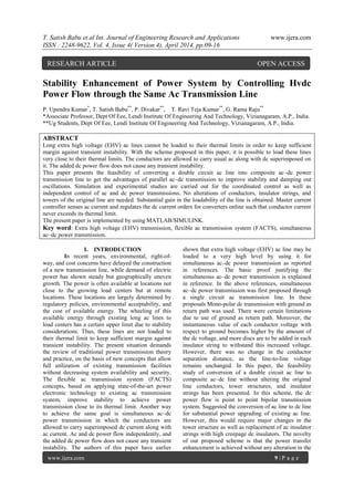
  • 1. T. Satish Babu et al Int. Journal of Engineering Research and Applications www.ijera.com ISSN : 2248-9622, Vol. 4, Issue 4( Version 4), April 2014, pp.09-16 www.ijera.com 9 | P a g e Stability Enhancement of Power System by Controlling Hvdc Power Flow through the Same Ac Transmission Line P. Upendra Kumar* , T. Satish Babu** , P. Divakar** , T. Ravi Teja Kumar** , G. Rama Raju** *Associate Professor, Dept Of Eee, Lendi Institute Of Engineering And Technology, Vizianagaram, A.P., India. **Ug Students, Dept Of Eee, Lendi Institute Of Engineering And Technology, Vizianagaram, A.P., India. ABSTRACT Long extra high voltage (EHV) ac lines cannot be loaded to their thermal limits in order to keep sufficient margin against transient instability. With the scheme proposed in this paper, it is possible to load these lines very close to their thermal limits. The conductors are allowed to carry usual ac along with dc superimposed on it. The added dc power flow does not cause any transient instability. This paper presents the feasibility of converting a double circuit ac line into composite ac–dc power transmission line to get the advantages of parallel ac–dc transmission to improve stability and damping out oscillations. Simulation and experimental studies are carried out for the coordinated control as well as independent control of ac and dc power transmissions. No alterations of conductors, insulator strings, and towers of the original line are needed. Substantial gain in the loadability of the line is obtained. Master current controller senses ac current and regulates the dc current orders for converters online such that conductor current never exceeds its thermal limit. The present paper is implemented by using MATLAB/SIMULINK. Key word: Extra high voltage (EHV) transmission, flexible ac transmission system (FACTS), simultaneous ac–dc power transmission. I. INTRODUCTION In recent years, environmental, right-of- way, and cost concerns have delayed the construction of a new transmission line, while demand of electric power has shown steady but geographically uneven growth. The power is often available at locations not close to the growing load centers but at remote locations. These locations are largely determined by regulatory policies, environmental acceptability, and the cost of available energy. The wheeling of this available energy through existing long ac lines to load centers has a certain upper limit due to stability considerations. Thus, these lines are not loaded to their thermal limit to keep sufficient margin against transient instability. The present situation demands the review of traditional power transmission theory and practice, on the basis of new concepts that allow full utilization of existing transmission facilities without decreasing system availability and security. The flexible ac transmission system (FACTS) concepts, based on applying state-of-the-art power electronic technology to existing ac transmission system, improve stability to achieve power transmission close to its thermal limit. Another way to achieve the same goal is simultaneous ac–dc power transmission in which the conductors are allowed to carry superimposed dc current along with ac current. Ac and dc power flow independently, and the added dc power flow does not cause any transient instability. The authors of this paper have earlier shown that extra high voltage (EHV) ac line may be loaded to a very high level by using it for simultaneous ac–dc power transmission as reported in references. The basic proof justifying the simultaneous ac–dc power transmission is explained in reference. In the above references, simultaneous ac–dc power transmission was first proposed through a single circuit ac transmission line. In these proposals Mono-polar dc transmission with ground as return path was used. There were certain limitations due to use of ground as return path. Moreover, the instantaneous value of each conductor voltage with respect to ground becomes higher by the amount of the dc voltage, and more discs are to be added in each insulator string to withstand this increased voltage. However, there was no change in the conductor separation distance, as the line-to-line voltage remains unchanged. In this paper, the feasibility study of conversion of a double circuit ac line to composite ac–dc line without altering the original line conductors, tower structures, and insulator strings has been presented. In this scheme, the dc power flow is point to point bipolar transmission system. Suggested the conversion of ac line to dc line for substantial power upgrading of existing ac line. However, this would require major changes in the tower structure as well as replacement of ac insulator strings with high creepage dc insulators. The novelty of our proposed scheme is that the power transfer enhancement is achieved without any alteration in the RESEARCH ARTICLE OPEN ACCESS
  • 2. T. Satish Babu et al Int. Journal of Engineering Research and Applications www.ijera.com ISSN : 2248-9622, Vol. 4, Issue 4( Version 4), April 2014, pp.09-16 www.ijera.com 10 | P a g e existing EHV ac line. The main object is to gain the advantage of parallel ac–dc transmission and to load the line close to its thermal limit. II. SIMULTANEOUS AC – DC POWER TRANSMISSION 2.1 Basic concept Fig 2.1: Basic Scheme for composite AC-DC transmission Fig 2.1 depicts the basic scheme for simultaneous ac–dc power flow through a double circuit ac transmission line. The DC power is obtained through line commutated 12- pulse rectifier bridge used in conventional HVDC and injected to the neutral point of the zigzag connected secondary of sending end transformer and is reconverted to AC again by the conventional line commutated 12-pulse bridge inverter at the receiving end. The inverter bridge is again connected to the neutral of zig-zag connected winding of the receiving end transformer. The double circuit AC transmission line carriers both three-phase AC and DC power. Each conductor of each line carries one third of the total DC current along with ac current. Resistance being equal in all the three phases of secondary winding of zig-zag transformer as well as the three conductors of the line, the DC current is equally divided among all the three phases. The three conductors of the second line provide return path for the Dc current. Zig-zag connected winding is used at both ends to avoid saturation of transformer due to DC current. Two fluxes produced by the DC current (Id/3) flowing through each of a winding in each limb of the core of a zig-zag transformer are equal in magnitude and opposite in direction. So the net DC flux at any instant of time becomes zero in each limb of the core. Thus, the DC saturation of the core is avoided. A high value of reactor X d is used to reduce harmonics in DC current. In the absence of zero sequence and third harmonics or its multiple harmonic voltages, under normal operating conditions, the AC current flow through each transmission line will be restricted between the zig-zag connected windings and the three conductors of the transmission line. Even the presence of these components of voltages may only be able to produce negligible current through the ground due to high value of X d. Assuming the usual constant current control of rectifier and constant extinction angle control of inverter, the equivalent circuit of the scheme under normal steady-state operating condition is given in Fig. 2.2. Fig. 2.2 Equivalent circuit The dotted lines in the figure show the path of AC return current only. The second transmission line carries the return DC current Id , and each conductor of the line carries Id/3 along with the AC current per phase. Vdro and Vdio are the maximum values of rectifier and inverter side DC voltages and are equal to (3 ) times converter AC input line-to-line voltage. R, L, and C are the line parameters per phase of each line. Rcr, Rci are commutating resistances, and α, are firing and extinction angles of rectifier and inverter, respectively. Neglecting the resistive drops in the line conductors and transformer windings due to DC current, expressions for AC voltage and current, and for active and reactive powers in terms of A, B, C, and D parameters of each line may be written as Es=AER+BIR (2.1) IS=CER+DIR (2.2) PS+JQS=-ESE*R/B*+D*E2 R/B* (2.3) PR+JQR=-E*SER/B*-A*E2 R/B* (2.4) Neglecting AC resistive drop in the line and transformer, the DC power Pdr and Pdi of each rectifier and inverter may be expressed as Pdr= Vdr Id (2.5) Pdi= Vdi Id (2.6) Reactive powers required by the converters are Qdr= Pdr r (2.7) Qdi= Pdi I (2.8) r= ( α + α+ µr))/2 (2.9) i= ( α + α+ µi))/2 (2.10) μr and μi are commutation angles of inverter and rectifier, respectively, and total active and reactive powers at the two ends areTransmission loss for each line is PL= (PS+Pdr)-(PR+Pdi) (2.11)
  • 3. T. Satish Babu et al Int. Journal of Engineering Research and Applications www.ijera.com ISSN : 2248-9622, Vol. 4, Issue 4( Version 4), April 2014, pp.09-16 www.ijera.com 11 | P a g e Ia being the rms AC current per conductor at any point of the line, the total rms current per conductor becomes I= [Ia 2 +(Id/3)2 ]1/2 (2.12) Power loss for each line PL≈ 3I2 R (2.13) The net current I in any conductor is offseted from zero. In case of a fault in the transmission system, gate signals to all the SCRs are blocked and that to the bypass SCRs are released to protect rectifier and inverter bridges. The current in any conductor is no more offseted. Circuit breakers (CBs) are then tripped at both ends to isolate the faulty line. CBs connected at the two ends of transmission line interrupt current at natural current zeroes, and no special DC CB is required. Now, allowing the net current through the conductor equal to its thermal limit (Ith). I=[Ia 2 +(Id/3)2 ]1/2 (2.14) Let Vph be per-phase rms voltage of original ac line. Let Vph also Va be the per-phase voltage of ac component of composite AC-DC line with dc Vd voltage superimposed on it. As insulators remain unchanged, the peak voltage in both cases should be equal Vmax = Vph = Vd+ Va (2.15) Electric field produced by any conductor possesses a DC component superimpose on it a sinusoidally varying AC component. However, the instantaneous electric field polarity changes its sign twice in a cycle if (Vd/Va < 2) is insured. Therefore, higher creep age distance requirement for insulator discs used for HVDC lines are not required. Each conductor is to be insulated for Vmax, but the line-to line voltage has no DC component and VLL max = 6Va. Therefore, conductor-to-conductor separation distance of each line is determined only by rated AC voltage of the line. Allowing maximum permissible voltage offset such that the composite voltage wave just touches zero in each every cycle; Vd= Vph/ and Va = Vph/ (2.16) The total power transfer through the double circuit line before conversion is as follows: P’total ≈ 3 Vph 2 1/X (2.17) Where X is the transfer reactance per phase of the double circuit line, 1 and is the power angle between the voltages at the two ends. To keep sufficient stability margin, 1 is generally kept low for long lines and seldom exceeds 30o. With the increasing length of line, the load ability of the line is decreased. An approximate value of 1 may be computed from the load ability curve by knowing the values of surge impedance loading (SIL) and transfer reactance X of the line. P’total = 2.M.SIL (2.18) Where M is the multiplying factor and its magnitude decreases with the length of line. The value of M can be obtained from the load ability curve. The total power was transfer through the composite line. Ptotal = Pac + Pdc = 3Va 2 2/X+2VdId (2.19) The power angle 2 between the AC voltages at the two ends of the composite line may be increased to a high value due to fast controllability of DC component of power. For a constant value of total power, Pac may be modulated by fast control of the current controller of DC power converters. Approximate value of AC current per phase per circuit of the double circuit line may be computed as Ia= V( /2)/X (2.20) The rectifier DC current order is adjusted online as Id=3 Ith *2 -Ia *2 (2.21) Preliminary qualitative analysis suggests that commonly used techniques in HVDC/AC system may be adopted for the purpose of the design of protective scheme, filter, and instrumentation network to be used with the composite line for simultaneous AC-DC power flow. In case of a fault in the transmission system, gate signals to all the SCRs are blocked and that to the bypass SCRs are released to protect rectifier and inverter bridges. CBs are then tripped at both ends to isolate the complete system. A surge diverter connected between the zig- zag neutral and the ground protects the converter bridge against any over voltage. 2.2 Economic consideration To get the advantages of parallel AC–DC transmission in order to improve stability and damping oscillations, the conversion of a double circuit AC line for simultaneous AC–DC power flow has been considered such that no alterations of conductor, insulator string and tower structure of the original line are required. The optimum values of AC phase and DC voltages of the converted line are 1/2 and 1/√2 times the phase voltage before conversion, respectively. The cost of transmission line includes the investment and operational costs. The investment includes costs of Right of Way (RoW), transmission tower, conductors, insulators, labour and terminal equipments. The operational costs include mainly the cost of losses. Additional costs of compensation and its terminal equipments also influences the AC line cost. DC transmission does not require compensation but the terminal equipment costs are increased due to the presence of converters and filters. Replacement of Y-connected transformer in simultaneous AC–DC
  • 4. T. Satish Babu et al Int. Journal of Engineering Research and Applications www.ijera.com ISSN : 2248-9622, Vol. 4, Issue 4( Version 4), April 2014, pp.09-16 www.ijera.com 12 | P a g e power transmission with zig-zag transformer is not likely to increase the cost, because it transfers only 25% of total power by transformer action. Also, the AC voltage reduces to 50% of the original AC voltage. However, the neutral point of this transformer needs insulation to withstand DC voltage. The load ability is observed to get doubled or even more with the simultaneous AC–DC power flow for a line with length of 500 km or longer. When an existing AC line is converted to simultaneous AC–DC line, instead of adding separate parallel DC, the additional investment on new DC line and on AC line compensations are saved. III.MODELLING OF COMPOSITE AC-DC SYSTEM Fig 3: Simulink Model of Simultaneous AC-DC Transmission IV.PROPOSED APPLICATIONS 1. Long EHV ac lines can not be loaded to their thermal limit to keep sufficient margin against transient instability and to keep voltage regulation within allowable limit, the simultaneous power flow does not imposed any extra burden on stability of the system, rather it improves the stability. The resistive drop due to dc current being very small in comparison to impedance drop due to ac current, there is also no appreciable change in voltage regulation due to superimposed dc current. 2. Therefore one possible application of simultaneous ac-dc transmission is to load the line close to its thermal limit by transmitting additional dc power. Figure3 shows the variation of Pt/Pac for changing values of k and x at unity power factor. However, it is to be noted that additional conductor insulation is to be provided due to insertion of dc. 3. Necessity of additional dc power transmission will be experienced maximum during peak load period which is characterized with lower than rate voltage. If dc power is injected during the peak loading period only with V d being in the range of 5% to 10% of E ph, the same transmission line without having any enhanced insulation level may be allowed to be used For 10.2% more power may be transmitted. 4. By adding a few more discs in insulator strings of each phase conductor with appropriate modifications in cross-arms of towers insulation level between phase to ground may be increased to a high value, which permits proportional increase in Emax, Therefore higher value of Vd may be used to increase dc and total power flow through the line. This modification in the exiting ac lines is justified due to high cost of a separate HVDC line. 5. With the very fast electronic control of firing angle (α) and extinction angle ( ) of the converters, the fast control of dc power may also be used to improve dynamic stability and damping out oscillations in the system similar to that of the ac-dc parallel transmission lines. 6. Control of α and also controls the rectifier and inverter VAR requirement and therefore, may be used to control the voltage profile of the
  • 5. T. Satish Babu et al Int. Journal of Engineering Research and Applications www.ijera.com ISSN : 2248-9622, Vol. 4, Issue 4( Version 4), April 2014, pp.09-16 www.ijera.com 13 | P a g e transmission line during low load condition and works as inductive shunt compensation. It may also be considered that the capacitive VAR of the transmission line is supplying the whole or part of the inductive VAR requirement of the converter system. In pure HVDC system capacitance of transmission line cannot be utilized to compensate inductive VAR. 7. The independent and fast control of active and reactive power associated with dc, superimposed with the normal ac active and reactive power may be considered to be working as another component of FACTS. 8. Simultaneous ac-dc power transmission may find its application in some special cases of LV and MV distribution system. When 3-phase power in addition to dc power is supplied to a location very near to a furnace or to a work place having very high ambient temperature, rectification of 3- phase supply is not possible at that location using semiconductor rectifier. In such place simultaneous ac-dc transmission is advantageous. In air craft 3-phase loads are generally fed with higher frequency supply of about 400Hz and separate line is used for dc loads. Skin effect restricts the optimum use of distribution wires at high frequency. Simultaneous ac-dc power transmission reduces both volume and weight of distributors. 9. Another possible application is the transmission of dc power generated by PV solar cells directly to remote dc loads through 3-phase ac line. In all cases of separate dc supply filter networks are not required. V. SIMULATED RESULTS
  • 6. T. Satish Babu et al Int. Journal of Engineering Research and Applications www.ijera.com ISSN : 2248-9622, Vol. 4, Issue 4( Version 4), April 2014, pp.09-16 www.ijera.com 14 | P a g e Inverter side voltage Inverter side current Active power source side Reactive power source side Active power
  • 7. T. Satish Babu et al Int. Journal of Engineering Research and Applications www.ijera.com ISSN : 2248-9622, Vol. 4, Issue 4( Version 4), April 2014, pp.09-16 www.ijera.com 15 | P a g e Reactive power VI.CONCLUSIONS The feasibility to convert ac transmission line to a composite ac–dc line has been demonstrated. The line is loaded to its thermal limit with the superimposed dc current. The dc power flow does not impose any stability problem. The advantage of parallel ac–dc transmission is obtained. Dc current regulator may modulate ac power flow. There is no need for any modification in the size of conductors, insulator strings, and towers structure of the original line. The optimum values of ac and dc voltage components of the converted composite line are 1/2 and times the ac voltage before conversion, respectively. References [1] H. Rahman, B.H. Khan, Power upgrading of double circuit ac transmission line by simultaneous ac–dc power transmission, in: Proceedings The IEEE, PES, Power India, 2006, doi:10.1109/POWERI.2006.1632623. [2] H. Rahman and B H Khan ―Stability Improvement of Power Systemby Simultaneous AC-DC Power Transmission‖ Electric Power System Research Journal, Elsevier, Paper Editorial ID No. EPSRD- 06-00732, Press Article No. EPSR-2560— Digital Object. [3] L. K. Gyugyi, ―Unified power flow concept for flexible A.C. transmission system,‖ Proc. Inst. Elect. Eng., p. 323, Jul. 1992. [4] L. K. Gyugyi et al., ―The unified power flow controller; a new approach to power transmission control,‖ IEEE Trans. Power Del., vol. 10, no. 2, pp. 1085–1097, Apr. 1995. [5] N. G. Hingorani, ―FACTS—flexible A.C. transmission system,‖ in Proc. Inst. Elect. Eng. 5th. Int. Conf. A.C. D.C. Power Transmission, London, U.K., 1991. [6] P. S. Kundur, Power System Stability and Control. New York: Mc-Graw-Hill, 1994.
  • 8. T. Satish Babu et al Int. Journal of Engineering Research and Applications www.ijera.com ISSN : 2248-9622, Vol. 4, Issue 4( Version 4), April 2014, pp.09-16 www.ijera.com 16 | P a g e [7] K. P. Basu and B. H. Khan, ―Simultaneous ac-dc power transmission,‖ Inst. Eng. (India) J.-EL, vol. 82, pp. 32–35, Jun. 2001. [8] H. Rahman and B. H. Khan, ―Enhanced power transfer by simultaneous transmission of AC-DC: a new FACTS concept,‖ in Proc. Inst. Elect. Eng. Conf. Power Electronics, Machines, Drives, Edinburgh, U.K., Mar. 31–Apr. 2 2004, vol. 1, pp. 186–191. [9] A. Clerici, L. Paris, and P. Danfors, ―HVDC conversion of HVAC line to provide substantial power upgrading,‖ IEEE Trans. Power Del., vol. 6, no. 1, pp. 324–333, Jan. 1991. [10] Padiyar, HVDC Power Transmission System. New Delhi, India: Wiley Eastern, 1993. [11] E. W. Kimbark, Direct Current Transmission. New York: Wiley, 1971, vol. I. [12] J. Arillaga and N. R.Watson, Computer Modelling of Electrical Power Systems. Chichester, U.K.: Wiley, 2003. [13] M. A. Chaudhry and D. P. Caroll, ―Coordinated active and reactive power modulation of multiterminal HVDC system,‖ IEEE Trans. Power App. Syst., vol. PAS-103, pp. 1480–1485, 1989. [14] K. R. Padiyar, M. A. Pai, and C. Radhakrishna, ―Analysis of D.C. link control for system stabilization,‖ in Proc. Inst. Elect. Eng. Conf. Publ. No. 205, London, U.K., 1981, pp. 145–148. [15] M. Stella, P. K. Dash, and K. P. Basu, ―A neuro-sliding mode controller for STATCOM,‖ Elect. Power Compon. Syst., vol. 32, pp. 131–147, Feb. 2004.