SlideShare a Scribd company logo
1 of 11
Download to read offline
UNIT 1 LOUD SPEAKER AND MICROPHONE
Loud speaker
Loud speaker is a transducer which converts electrical signal into sound signal. There are two types of
dynamic speaker electro dynamic and permanent magnet speaker
Electro dynamic speaker
In operation, a steady direct current flows through the field coil,
magnetizing the field structure as shown. The audio signal is
applied to a small coil (called the voice coil) of wire wrapped on an
insulated tube which is an extension of the speaker cone at the
center as shown.
The arrangement is such that the voice coil lies in the gap between
the north and south magnet poles. When current flows in one
direction through the voice coil, it creates a magnetic field which
reacts with the field in the gap and makes the cone move slightly to
the right. When the audio signal current reverses direction, it makes the cone move to the left. The audio
signal is always an alternating current, so as the current fluctuates in response to the power amplifier's
output signal, the speaker cone faithfully reproduces the variations of the audio signal as mechanical
motion, and the large surface area of the cone effectively generates a sound wave which is replica of
audio signal.
Permanent magnet dynamic loud speaker
The most popular type of loudspeaker today is the
permanent magnet dynamic type. Because of its
comparative simplicity of construction and design, the
precision that may be built into it, the ease with which
it is interfaced with other equipment, its easy
adaptability to many different applications, and its
comparative freedom from electrical trouble, the
dynamic loudspeaker has found acceptance in all
kinds of reproducing systems. It is found in the smallest pocket radios and is a major component of the most
elaborate theatre systems.
The PM speaker contains a very light coil of wire affixed to the diaphragm and located concentrically
around, within, or in front of the centre of the permanent magnet. The coil (voice coil) is free to move
in the field of the magnet. Electrical impulses, varying at an audio rate, are applied to the voice coil by
the amplifier. Because these impulses are constantiy changing in amplitude and direction, a changing
magnetic field is set up in the voice coil. This field reacts with the constant field of the permanent
magnet. The result is that the voice coil moves further into the gap when the fields are opposite and
attract, and farther out of the gap when they are alike and repel. This causes an in-and-out movement
of the diaphragm; consequently, we obtain sound waves from electrical impulses. The speed at which
the coil and diaphragm vibrate depends upon the frequency of the impulses. The distance that the
diaphragm moves in and out depends on their amplitude.
Piezo electric speakers
Piezoelectric speakers have a total different working principle than an electro dynamic speaker. There
is no coil, no magnetic field and no large current consumption. The heart of each piezoelectric speaker
is a ceramic disc that interacts when it feels a certain voltage difference. An increase of the signal
amplitude Vpp (Voltage peak to peak), will result in a larger piezo deformation and result in a larger
sound output
“Interactingwithvoltagevariations” “MoreVpp
createsmoresoundoutput”
Piezo ceramic speakers produce sound by the forward and backward movement of a flat membrane.
During this movement the membrane creates an air pressure wave in front and at the backside of the
membrane. A forward movement will create a slight overpressure at the front side and a slight under
pressure at the backside and vice versa. It is therefore important that the front and backside are
acoustically isolated from each other to avoid air pressure cancellation and consequently a serious
reduction of the sound output. When a speaker is mounted in a panel or in the wall of a housing, the
front side is acoustically isolated from the backside
Woofers
Woofer is the term commonly used for a loudspeaker
driver designed to produce low frequency sounds,
typically from around 40 hertz up to about a kilohertz
or higher. There are two types of low frequency
speaker, the commonly known woofer, and the more
recent addition the subwoofer. The latter is used for
the reproduction of frequencies below those produced
by the woofer and it is generally purchased as an add-
on to an existing system.
The low frequencies speaker provides the bass of any hi-fi system. Its sole purpose is to reduce the low
frequency notes of the program source. The prime requisite for low frequency reproduction is a large diaphragm
the larger the better. In addition to large size, the diaphragm must be of fairly heavy construction Light
diaphragms just can't hold up under the vibrations encountered under the lower audio ranges.
A woofer must be able to vibrate back and forth very easily i.e have high compliance. One way
to accomplish this is to have the diaphragm loosely connected to the frame. The gasketing that holds the
periphery of diaphragm to the frame basket is fastened so that it barely keeps the diaphragm from
slipping loose.
Rather than the loose suspension system, the cone is supported by a very flexible material so that it can be moved
very easily by the voice coil. The suspension is tight hut the sine wave at the diaphragm edge is made very flexible.
The large speakers have more extended lows, the smaller ones more extended highs.
A woofer must also have a large voice coil to handle considerable heat. The larger the voice coil, the more the
current produced by the amplifier output circuit and, therefore, the more the power the woofer can handle.
Finally, a strong magnet can be of great help to move the heavy voice coil and cone assembly too well. The better
the woofer, the heavier the magnet assembly (unless it's ceramic).
Tweeters
A tweeter is a loudspeaker designed to produce high audio frequencies, typically from
around 2,000 Hz to 20,000 Hz. Some tweeters can manage response up to 65 kHz.Nearly all tweeters are
electro-dynamic drivers, using a voice coil suspended within a fixed magnetic field. These designs
operate by applying current from the output of an amplifier circuit to a coil of wire, called a voice coil.
The voice coil produces a varying magnetic field, which works against the fixed magnetic field of a
magnet around which the cylindrical voice coil is suspended, forcing the voice coil and the diaphragm
attached to it to move. This mechanical movement exactly resembles the waveform of the electronic
signal supplied from the amplifier's output to the voice coil. Since the coil is attached to a diaphragm,
the vibratory motion of the voice coil transmits to the diaphragm; the diaphragm in turn vibrates the air
thus creating air motions or audio waves, which we hear as high sounds.
There are two main types of high frequency speakers; the well-known tweeter and the more recent super
tweeter. Super tweeters can be add-ons or they can be integral with the system. Six basic high-frequency
speakers (tweeters) exist.
(i) The cone is a physically disincentive version of the woofer.
(ii) The dome, so called because of its dome-shaped diaphragm.
(iii) The horn, so named because it is a horn.
(iv) The Heil air-motion transformer which uses the principle of lever in its operation, named after its
inventor, Dr. Oskar Heil.
(v) High polymer molecular-film tweeter, uses the piezoelectric effect for its principle of operation (used
exclusively by Pioneer).
(vi) The electrostatic tweeter works on the principle of attraction or repulsion between two metal plates.
Types of tweeters
Cone tweeter
Cone tweeters have the same basic design and form as a woofer with optimizations to operate at higher
frequencies. The optimizations usually are:
 a very small and light cone so it can move rapidly;
 cone materials chosen for stiffness (e.g., ceramic cones in one manufacturer's line), or good
damping properties (e.g., silk or coated fabric) or both;
 the suspension (or spider) is stiffer than for other
drivers—less flexibility is needed for high frequency
reproduction;
 small voice coils (3/4 inch is typical) and light (thin)
wire, which also helps the tweeter cone move rapidly.
Cone tweeters are relatively cheap, but do not have the
dispersion characteristics of domes. Thus they are routinely
seen in low cost applications such as factory car speakers,
shelf stereo systems, and boom boxes. Cone tweeters can also be found in older stereo hi-fi system
speakers designed and manufactured before the advent of the dome tweeter. They are now a rare sight in
modern hi-fi usage.
Dome tweeters
A dome tweeter is constructed
by attaching a voice coil to a dome,
which is attached to the magnet or the
top plate via a low compliance
suspension. These tweeters typically
do not have a frame or basket, but a
simple front plate attached to the
magnet assembly. Dome tweeters are
categorized by their voice coil diameter. The majority of dome tweeters presently used in hi-fi speakers
are 25 mm (1 in) in diameter. A variation is the ring radiator in which the 'suspension' of the cone or
dome becomes the major radiating element. These tweeters have different directivity characteristics
when compared to standard dome tweeters.
Horn tweeters
A horn tweeter is any of the above tweeters coupled to a flared or horn structure. Horns are used
for two purposes — to control
dispersion, and to couple the tweeter
diaphragm to the air for higher
efficiency. The tweeter in either
case is usually termed a
compression driver and is quite
different from more common types
of tweeters (see above). Properly
used, a horn improves the off-axis
response of the tweeter by controlling (i.e., reducing) the directivity of the tweeter. It can also improve
the efficiency of the tweeter by coupling the relatively high acoustic impedance of the driver to the
lower impedance of the air. The larger the horn, the lower the frequencies at which it can work, since
large horns provide coupling to the air at lower frequencies. There are different types of horns, including
radial and constant directivity (CD). Horn tweeters may have a somewhat 'different' sonic signature than
simple dome tweeters. Poorly designed horns, or improperly crossed-over horns, have predictable
problems in the accuracy of their output, and the load that they present to the amplifier. Perhaps
concerned about the image of poorly designed horns, some manufacturers use horn loaded tweeters, but
avoid using the term. Their euphemisms include "elliptical aperture" "Semi-horn" and "Directivity
controlled". These are, nonetheless, a form of horn loading.
Microphones
Microphones are a type of transducer - a device which converts energy from one form to another.
Microphones convert acoustical energy (sound waves) into electrical energy (the audio signal).
Different types of microphone have different ways of converting energy but they all share one thing in
common: The diaphragm. This is a thin piece of material (such as paper, plastic or aluminium) which
vibrates when it is struck by sound waves. In a typical hand-held mic like the one below, the diaphragm
is located in the head of the microphone.
When the diaphragm vibrates, it causes other components in the microphone to vibrate. These vibrations
are converted into an electrical current which becomes the audio signal.
Dynamic Microphone
Dynamic microphones are versatile and ideal for general-purpose use. They use a simple design
with few moving parts. They are relatively strong and flexible to rough handling. They are also better
suited to handling high volume levels, such as from certain musical instruments or amplifiers. They have
no internal amplifier and do not require batteries or external power.
Working Principle
When a magnet is moved near a coil of wire an
electrical current is generated in the wire. Using this
electromagnet principle, the dynamic microphone
uses a wire coil and magnet to create the audio signal.
The diaphragm is attached to the coil. When the
diaphragm vibrates in response to incoming sound
waves, the coil moves backwards and forwards past
the magnet. This creates a current in the coil which is
channeled from the microphone along wires.
Condenser Microphones
Condenser or capacitor, an electronic component which stores energy in the form of an electrostatic
field. The use of condenser micro phone is to
convert acoustical energy into electrical energy.
Condenser microphones require power from a
battery or external source. The resulting audio
signal is stronger signal than that from a
dynamic. Condensers also tend to be more
sensitive and responsive than dynamics, making
them well-suited to capturing subtle nuances in a
sound. They are not ideal for high-volume work,
as their sensitivity makes them prone to distort.
A capacitor has two plates with a voltage between them. In the condenser mic, one of these plates is
made of very light material and acts as the diaphragm. The diaphragm vibrates when struck by sound
waves, changing the distance between the two plates and therefore changing the capacitance.
Specifically, when the plates are closer together, capacitance increases and a charge current occurs.
When the plates are further apart, capacitance decreases and a discharge current occurs.
A voltage is required across the capacitor for this to work. This voltage is supplied either by a battery in
the mic or by external phantom power.
Carbon Microphone
The carbon microphone, also known as carbon button
microphone, button microphone, or carbon transmitter,It
consists of two metal plates separated by granules of carbon.
One plate is very thin and faces outward, acting as
a diaphragm. When sound waves strike this plate,
the pressure on the granules changes, which in turn changes
the electrical resistance between the plates. Higher pressure
lowers the resistance as the granules are pushed closer
together. As a steady direct current is passed between the
plates, the varying resistance results in a modulation of the
current at the same frequency of the impinging sound waves.
In telephony, this signal is directly passed through a telephone
system to the central office, or it is electronically amplified in
other sound systems, such as a public address system or
a recording device. The frequency response of the carbon
microphone, however, is limited to a narrow range, and the device produces significant electrical noise.
Limitations of carbon microphone
One disadvantage of carbon microphones is that of a constant BACKGROUND HISS (hissing
noise)which results from random changes in the resistance between individual carbon granules. Other
disadvantages are reduced sensitivity and distortion that may result from the granules packing or
sticking together. The carbon microphone also has a limited frequency response. Still
another disadvantage is a requirement for an external voltage source. The disadvantages, however,
are offset by advantages that make its use in military applications widespread. It is lightweight,
rugged, and can produce an extremely high output.
CRYSTAL MICROPHONE:
The crystal microphone uses the PIEZO ELECTRIC EFFECT of Rochelle salt, quartz, or other
crystalline materials. This means that when mechanical stress is placed upon the material, a voltage
electromagnetic force (EMF) is generated. Since Rochelle salt has the largest voltage output for a given
mechanical stress, it is the most commonly used crystal in microphones. In figure A the crystal is mounted so
that the sound waves strike it directly. In figure B a diaphragm that is mechanically linked to the
crystal so that the sound waves are indirectly
coupled to the crystal.
Piezo electric speakers
WIRELESS MICROPHONE:
A wireless microphone, as the name implies, is a microphone without a physical cable
connecting it directly to the sound recording or amplifying equipment with which it is associated. Also
known as a radio microphone, it has a small, battery-powered radio transmitter in the microphone body,
which transmits the audio signal from the microphone by radio waves to a nearby receiver unit, which
recovers the audio. The other audio equipment is connected to the receiver unit by cable. Wireless
microphones are widely used in the entertainment industry, television broadcasting, and public speaking
to allow public speakers, interviewers, performers, and entertainers to move about freely while using a
microphone to amplify their voices.
There are many different standards, frequencies and transmission technologies used to replace
the microphone's cable connection and make it into a wireless microphone. They can transmit, for
example, in radio waves using UHF or VHF frequencies, FM, AM, or various digital modulation
schemes. Some low cost models use infrared light. Infrared microphones require a direct line of sight
between the microphone and the receiver, while costlier radio frequency models do not.
ADVANTAGES AND DISADVANTAGES
The advantages are:
 Greater freedom of movement for the artist or speaker.
 Avoidance of cabling problems common with wired microphones, caused by constant moving
and stressing the cables.
 Reduction of cable "trip hazards" in the performance space
The disadvantages are:
 Sometimes limited range (a wired balanced XLR microphone can run up to 300 ft or 100
meters). Some wireless systems have a shorter range, while more expensive models can exceed
that distance.
 Possible interference with or, more often, from other radio equipment or other radio
microphones, though models with many frequency-synthesized switch-selectable channels are
now plentiful and cost effective.
 Operation time is limited relative to battery life; it is shorter than a normal condenser
microphone due to greater drain on batteries from transmitting circuitry, and from circuitry
giving extra features, if present.
 Noise or dead spots.
 Limited number of operating microphones at the same time and place, due to the limited number
of radio channels.
Characteristics of Microphones
There are many types of microphones available. Each has certain advantages and disadvantages. Hence the
selection of microphones depends upon the certain characteristics as below:
(1) Output level; (2) Frequency response; (3) Output impedance and (4) Directivity.
(1) Output level: -
The output level of a microphone governs the amount of amplification that must be available for use with the
microphone. The output level of microphone is usually given in dB preceded by a minus sign. The minus sign
means that the output level is so many dB below the reference level of 1milliwatt for a specified sound pressure.
(2) Frequency response: -
The frequency response of a microphone is a rating of the fidelity of relative output voltage which results from
sound waves of different frequencies. The simplest way to find a complete picture of the frequency response
characteristics of a microphone is to plot a curve of its output voltage v/s input frequency. Since good
microphones are relatively flat over their range, it is often considered sufficient to specify the range over which
their output does not vary more than ±1-2 dB.
(3) Output impedance: -
A microphone, like any other component with electrical i/p of o/p, has a value of impedance. When a microphone
is connected to an amplifier, a complete circuit is formed and electric current flows whenever a sound causes the
microphone to generate an electrical voltage.
For most high quality microphones impedance is low, a few ohms ranging upto a hundred ohms or so. The
importance of microphone impedance is not a matter of the precise value but of the ability of the microphone and
the recorder to be matched together. High impedance microphones must be connected must be connected into a
recorder with high impedance input, otherwise both the signal amplitude and the frequency range will be
adversely affected.
Directional Properties
Every microphone has a property known as directionality. This describes the microphone's sensitivity to
sound from various directions. Some microphones pick up sound equally from all directions, others pick
up sound only from one direction or a particular combination of directions. The types of directionality
are divided into three main categories:
1. Omnidirectional
Picks up sound evenly from all directions (omni means "all" or "every").
2. Unidirectional
Picks up sound predominantly from one direction. This includes cardioid and hypercardioid
microphones (see below).
3. Bidirectional
Picks up sound from two opposite directions.
To help understand a the directional properties of a particular microphone, user manuals and
promotional material often include a graphical representation of the microphone's directionality. This
graph is called a polar pattern. Some typical examples are shown below.
Omnidirectional
Captures sound equally from all directions.
Uses: Capturing ambient noise; Situations where sound is coming from many
directions; Situations where the mic position must remain fixed while the sound
source is moving.
Notes:
 Although omnidirectional mics are very useful in the right situation, picking up sound from every
direction is not usually what you need. Omni sound is very general and unfocused - if you are trying
to capture sound from a particular subject or area it is likely to be overwhelmed by other noise.
Cardioid
Cardioid means "heart-shaped", which is the type of pick-up pattern these mics use.
Sound is picked up mostly from the front, but to a lesser extent the sides as well.
Uses: Emphasizing sound from the direction the mic is pointed whilst leaving some
latitude for mic movement and ambient noise.
Notes:
 The cardioid is a very versatile microphone, ideal for general use. Handheld mics are usually cardioid.
 There are many variations of the cardioid pattern (such as the hypercardioid below).
Hypercardioid
This is exaggerated version of the cardioid pattern. It is very directional and
eliminates most sound from the sides and rear. Due to the long thin design of
hypercardioids, they are often referred to as shotgun microphones.
Uses: Isolating the sound from a subject or direction when there is a lot of ambient
noise; Picking up sound from a subject at a distance.
Notes:
 By removing all the ambient noise, unidirectional sound can sometimes be a little unnatural. It may
help to add a discreet audio bed from another mic (i.e. constant background noise at a low level).
 You need to be careful to keep the sound consistent. If the mic doesn't stay pointed at the subject you
will lose the audio.
 Shotguns can have an area of increased sensitivity directly to the rear.
Bidirectional
Uses a figure-of-eight pattern and picks up sound equally from two opposite
directions.
Uses: As you can imagine, there aren't a lot of situations which require this polar
pattern. One possibility would be an interview with two people facing each other
(with the mic between them).

More Related Content

What's hot

Pre-emphasis and de-emphasis circuits
Pre-emphasis and de-emphasis circuitsPre-emphasis and de-emphasis circuits
Pre-emphasis and de-emphasis circuitsShivangiSingh241
 
Frequency Response Analysis
Frequency Response AnalysisFrequency Response Analysis
Frequency Response AnalysisHussain K
 
Acoustics [Microphones]
Acoustics [Microphones]Acoustics [Microphones]
Acoustics [Microphones]Ethar Sayed
 
Structures for FIR systems
Structures for FIR systemsStructures for FIR systems
Structures for FIR systemsChandan Taluja
 
Ppt Digital Electronics
Ppt Digital ElectronicsPpt Digital Electronics
Ppt Digital ElectronicsNaval Kush
 
Basics of digital filters
Basics of digital filtersBasics of digital filters
Basics of digital filtersSmile Hossain
 
Coherent and Non-coherent detection of ASK, FSK AND QASK
Coherent and Non-coherent detection of ASK, FSK AND QASKCoherent and Non-coherent detection of ASK, FSK AND QASK
Coherent and Non-coherent detection of ASK, FSK AND QASKnaimish12
 
Signals and systems( chapter 1)
Signals and systems( chapter 1)Signals and systems( chapter 1)
Signals and systems( chapter 1)Fariza Zahari
 
Amplitude Modulation ppt
Amplitude Modulation pptAmplitude Modulation ppt
Amplitude Modulation pptPriyanka Mathur
 
Butterworth filter design
Butterworth filter designButterworth filter design
Butterworth filter designSushant Shankar
 
Modulation, Frequency Modulation, Phase Modulation, Amplitude Modulation
Modulation, Frequency Modulation, Phase Modulation, Amplitude ModulationModulation, Frequency Modulation, Phase Modulation, Amplitude Modulation
Modulation, Frequency Modulation, Phase Modulation, Amplitude ModulationWaqas Afzal
 
Multiband Transceivers - [Chapter 7] Multi-mode/Multi-band GSM/GPRS/TDMA/AMP...
Multiband Transceivers - [Chapter 7]  Multi-mode/Multi-band GSM/GPRS/TDMA/AMP...Multiband Transceivers - [Chapter 7]  Multi-mode/Multi-band GSM/GPRS/TDMA/AMP...
Multiband Transceivers - [Chapter 7] Multi-mode/Multi-band GSM/GPRS/TDMA/AMP...Simen Li
 

What's hot (20)

Pre-emphasis and de-emphasis circuits
Pre-emphasis and de-emphasis circuitsPre-emphasis and de-emphasis circuits
Pre-emphasis and de-emphasis circuits
 
Frequency Response Analysis
Frequency Response AnalysisFrequency Response Analysis
Frequency Response Analysis
 
Acoustics [Microphones]
Acoustics [Microphones]Acoustics [Microphones]
Acoustics [Microphones]
 
Receivers
ReceiversReceivers
Receivers
 
Structures for FIR systems
Structures for FIR systemsStructures for FIR systems
Structures for FIR systems
 
Butterworth filter
Butterworth filterButterworth filter
Butterworth filter
 
Ppt Digital Electronics
Ppt Digital ElectronicsPpt Digital Electronics
Ppt Digital Electronics
 
Basics of digital filters
Basics of digital filtersBasics of digital filters
Basics of digital filters
 
Amplitude modulation
Amplitude modulationAmplitude modulation
Amplitude modulation
 
Coherent and Non-coherent detection of ASK, FSK AND QASK
Coherent and Non-coherent detection of ASK, FSK AND QASKCoherent and Non-coherent detection of ASK, FSK AND QASK
Coherent and Non-coherent detection of ASK, FSK AND QASK
 
Oscillators
OscillatorsOscillators
Oscillators
 
An Introduction to Microphones
An Introduction to MicrophonesAn Introduction to Microphones
An Introduction to Microphones
 
Signals and systems( chapter 1)
Signals and systems( chapter 1)Signals and systems( chapter 1)
Signals and systems( chapter 1)
 
Amplitude Modulation ppt
Amplitude Modulation pptAmplitude Modulation ppt
Amplitude Modulation ppt
 
Lec # 07 parallel operation of synchronous generators
Lec # 07 parallel operation of synchronous generatorsLec # 07 parallel operation of synchronous generators
Lec # 07 parallel operation of synchronous generators
 
Eca unit i.ppt
Eca unit i.pptEca unit i.ppt
Eca unit i.ppt
 
Butterworth filter design
Butterworth filter designButterworth filter design
Butterworth filter design
 
Basics of Oscillator
Basics of OscillatorBasics of Oscillator
Basics of Oscillator
 
Modulation, Frequency Modulation, Phase Modulation, Amplitude Modulation
Modulation, Frequency Modulation, Phase Modulation, Amplitude ModulationModulation, Frequency Modulation, Phase Modulation, Amplitude Modulation
Modulation, Frequency Modulation, Phase Modulation, Amplitude Modulation
 
Multiband Transceivers - [Chapter 7] Multi-mode/Multi-band GSM/GPRS/TDMA/AMP...
Multiband Transceivers - [Chapter 7]  Multi-mode/Multi-band GSM/GPRS/TDMA/AMP...Multiband Transceivers - [Chapter 7]  Multi-mode/Multi-band GSM/GPRS/TDMA/AMP...
Multiband Transceivers - [Chapter 7] Multi-mode/Multi-band GSM/GPRS/TDMA/AMP...
 

Similar to LOUD SPEAKER AND MICROPHONE

Similar to LOUD SPEAKER AND MICROPHONE (20)

The Speakers
The SpeakersThe Speakers
The Speakers
 
Prac3 LOUDSPEAKER
Prac3 LOUDSPEAKERPrac3 LOUDSPEAKER
Prac3 LOUDSPEAKER
 
Microphones and speakers
Microphones and speakersMicrophones and speakers
Microphones and speakers
 
Consumer Electronics Lecture 2 microphone.pptx
Consumer Electronics Lecture 2 microphone.pptxConsumer Electronics Lecture 2 microphone.pptx
Consumer Electronics Lecture 2 microphone.pptx
 
Audio spotlighting
Audio spotlightingAudio spotlighting
Audio spotlighting
 
Loudspeakers
LoudspeakersLoudspeakers
Loudspeakers
 
Dynamic microphone
Dynamic microphoneDynamic microphone
Dynamic microphone
 
Speaker Installation is essential for success at Houston
 Speaker Installation is essential for success at Houston Speaker Installation is essential for success at Houston
Speaker Installation is essential for success at Houston
 
Audio devices and applications
Audio devices and applicationsAudio devices and applications
Audio devices and applications
 
LaudSpeaker Presentation
LaudSpeaker PresentationLaudSpeaker Presentation
LaudSpeaker Presentation
 
Presentation unit 1.pptx
Presentation unit 1.pptxPresentation unit 1.pptx
Presentation unit 1.pptx
 
Working Principals of Microphones
Working Principals of MicrophonesWorking Principals of Microphones
Working Principals of Microphones
 
Audio
AudioAudio
Audio
 
Laxman radio PPT
Laxman radio PPTLaxman radio PPT
Laxman radio PPT
 
SENSORS_UNIT-3.pptx
SENSORS_UNIT-3.pptxSENSORS_UNIT-3.pptx
SENSORS_UNIT-3.pptx
 
Microphones
MicrophonesMicrophones
Microphones
 
Sound unit 4
Sound unit 4Sound unit 4
Sound unit 4
 
Loudspeaker- direct radiating type and horn type.pptx
Loudspeaker- direct radiating type and horn type.pptxLoudspeaker- direct radiating type and horn type.pptx
Loudspeaker- direct radiating type and horn type.pptx
 
Audio spot light
Audio spot lightAudio spot light
Audio spot light
 
Sound unit 4
Sound unit 4Sound unit 4
Sound unit 4
 

More from Tamilarasan N

PHASE LOCKED LOOP AND TIMER
PHASE LOCKED LOOP AND TIMERPHASE LOCKED LOOP AND TIMER
PHASE LOCKED LOOP AND TIMERTamilarasan N
 
Analog IC Application
Analog IC ApplicationAnalog IC Application
Analog IC ApplicationTamilarasan N
 
OPERATIONAL AMPLIFIERS
OPERATIONAL AMPLIFIERSOPERATIONAL AMPLIFIERS
OPERATIONAL AMPLIFIERSTamilarasan N
 
Digital integrated circuits
Digital integrated circuitsDigital integrated circuits
Digital integrated circuitsTamilarasan N
 
telecommunication system
telecommunication systemtelecommunication system
telecommunication systemTamilarasan N
 
Telecommunication Systems
Telecommunication SystemsTelecommunication Systems
Telecommunication SystemsTamilarasan N
 
Optical recording system
Optical recording systemOptical recording system
Optical recording systemTamilarasan N
 
Television standards and systems
Television standards and systemsTelevision standards and systems
Television standards and systemsTamilarasan N
 
Performance of the MIMO-MC-CDMA System with MMSE Equalization
Performance of the MIMO-MC-CDMA System with MMSE EqualizationPerformance of the MIMO-MC-CDMA System with MMSE Equalization
Performance of the MIMO-MC-CDMA System with MMSE EqualizationTamilarasan N
 
PERFORMANCE OF MIMO MC-CDMA SYSTEM WITH CHANNEL ESTIMATION AND MMSE EQUALIZATION
PERFORMANCE OF MIMO MC-CDMA SYSTEM WITH CHANNEL ESTIMATION AND MMSE EQUALIZATIONPERFORMANCE OF MIMO MC-CDMA SYSTEM WITH CHANNEL ESTIMATION AND MMSE EQUALIZATION
PERFORMANCE OF MIMO MC-CDMA SYSTEM WITH CHANNEL ESTIMATION AND MMSE EQUALIZATIONTamilarasan N
 
Mmse partially connected hybrid beam forming in mimo ofdm
Mmse partially connected hybrid beam forming in mimo ofdmMmse partially connected hybrid beam forming in mimo ofdm
Mmse partially connected hybrid beam forming in mimo ofdmTamilarasan N
 
Hybrid Adaptive Channel Estimation Technique in Time and Frequency Domain for...
Hybrid Adaptive Channel Estimation Technique in Time and Frequency Domain for...Hybrid Adaptive Channel Estimation Technique in Time and Frequency Domain for...
Hybrid Adaptive Channel Estimation Technique in Time and Frequency Domain for...Tamilarasan N
 
Automated brain tumor detection and segmentation from mri images using adapti...
Automated brain tumor detection and segmentation from mri images using adapti...Automated brain tumor detection and segmentation from mri images using adapti...
Automated brain tumor detection and segmentation from mri images using adapti...Tamilarasan N
 
Performance improvement of mimo mc cdma system using equalization, beamformin...
Performance improvement of mimo mc cdma system using equalization, beamformin...Performance improvement of mimo mc cdma system using equalization, beamformin...
Performance improvement of mimo mc cdma system using equalization, beamformin...Tamilarasan N
 
Performance improvement of mimo mc cdma system using relay and itbf
Performance improvement of mimo mc  cdma system using relay and itbfPerformance improvement of mimo mc  cdma system using relay and itbf
Performance improvement of mimo mc cdma system using relay and itbfTamilarasan N
 

More from Tamilarasan N (16)

PHASE LOCKED LOOP AND TIMER
PHASE LOCKED LOOP AND TIMERPHASE LOCKED LOOP AND TIMER
PHASE LOCKED LOOP AND TIMER
 
Analog IC Application
Analog IC ApplicationAnalog IC Application
Analog IC Application
 
OPERATIONAL AMPLIFIERS
OPERATIONAL AMPLIFIERSOPERATIONAL AMPLIFIERS
OPERATIONAL AMPLIFIERS
 
Digital integrated circuits
Digital integrated circuitsDigital integrated circuits
Digital integrated circuits
 
telecommunication system
telecommunication systemtelecommunication system
telecommunication system
 
Home appliances
Home appliancesHome appliances
Home appliances
 
Telecommunication Systems
Telecommunication SystemsTelecommunication Systems
Telecommunication Systems
 
Optical recording system
Optical recording systemOptical recording system
Optical recording system
 
Television standards and systems
Television standards and systemsTelevision standards and systems
Television standards and systems
 
Performance of the MIMO-MC-CDMA System with MMSE Equalization
Performance of the MIMO-MC-CDMA System with MMSE EqualizationPerformance of the MIMO-MC-CDMA System with MMSE Equalization
Performance of the MIMO-MC-CDMA System with MMSE Equalization
 
PERFORMANCE OF MIMO MC-CDMA SYSTEM WITH CHANNEL ESTIMATION AND MMSE EQUALIZATION
PERFORMANCE OF MIMO MC-CDMA SYSTEM WITH CHANNEL ESTIMATION AND MMSE EQUALIZATIONPERFORMANCE OF MIMO MC-CDMA SYSTEM WITH CHANNEL ESTIMATION AND MMSE EQUALIZATION
PERFORMANCE OF MIMO MC-CDMA SYSTEM WITH CHANNEL ESTIMATION AND MMSE EQUALIZATION
 
Mmse partially connected hybrid beam forming in mimo ofdm
Mmse partially connected hybrid beam forming in mimo ofdmMmse partially connected hybrid beam forming in mimo ofdm
Mmse partially connected hybrid beam forming in mimo ofdm
 
Hybrid Adaptive Channel Estimation Technique in Time and Frequency Domain for...
Hybrid Adaptive Channel Estimation Technique in Time and Frequency Domain for...Hybrid Adaptive Channel Estimation Technique in Time and Frequency Domain for...
Hybrid Adaptive Channel Estimation Technique in Time and Frequency Domain for...
 
Automated brain tumor detection and segmentation from mri images using adapti...
Automated brain tumor detection and segmentation from mri images using adapti...Automated brain tumor detection and segmentation from mri images using adapti...
Automated brain tumor detection and segmentation from mri images using adapti...
 
Performance improvement of mimo mc cdma system using equalization, beamformin...
Performance improvement of mimo mc cdma system using equalization, beamformin...Performance improvement of mimo mc cdma system using equalization, beamformin...
Performance improvement of mimo mc cdma system using equalization, beamformin...
 
Performance improvement of mimo mc cdma system using relay and itbf
Performance improvement of mimo mc  cdma system using relay and itbfPerformance improvement of mimo mc  cdma system using relay and itbf
Performance improvement of mimo mc cdma system using relay and itbf
 

Recently uploaded

Software Engineering Methodologies (overview)
Software Engineering Methodologies (overview)Software Engineering Methodologies (overview)
Software Engineering Methodologies (overview)eniolaolutunde
 
mini mental status format.docx
mini    mental       status     format.docxmini    mental       status     format.docx
mini mental status format.docxPoojaSen20
 
Organic Name Reactions for the students and aspirants of Chemistry12th.pptx
Organic Name Reactions  for the students and aspirants of Chemistry12th.pptxOrganic Name Reactions  for the students and aspirants of Chemistry12th.pptx
Organic Name Reactions for the students and aspirants of Chemistry12th.pptxVS Mahajan Coaching Centre
 
Arihant handbook biology for class 11 .pdf
Arihant handbook biology for class 11 .pdfArihant handbook biology for class 11 .pdf
Arihant handbook biology for class 11 .pdfchloefrazer622
 
How to Make a Pirate ship Primary Education.pptx
How to Make a Pirate ship Primary Education.pptxHow to Make a Pirate ship Primary Education.pptx
How to Make a Pirate ship Primary Education.pptxmanuelaromero2013
 
Kisan Call Centre - To harness potential of ICT in Agriculture by answer farm...
Kisan Call Centre - To harness potential of ICT in Agriculture by answer farm...Kisan Call Centre - To harness potential of ICT in Agriculture by answer farm...
Kisan Call Centre - To harness potential of ICT in Agriculture by answer farm...Krashi Coaching
 
SOCIAL AND HISTORICAL CONTEXT - LFTVD.pptx
SOCIAL AND HISTORICAL CONTEXT - LFTVD.pptxSOCIAL AND HISTORICAL CONTEXT - LFTVD.pptx
SOCIAL AND HISTORICAL CONTEXT - LFTVD.pptxiammrhaywood
 
MENTAL STATUS EXAMINATION format.docx
MENTAL     STATUS EXAMINATION format.docxMENTAL     STATUS EXAMINATION format.docx
MENTAL STATUS EXAMINATION format.docxPoojaSen20
 
Employee wellbeing at the workplace.pptx
Employee wellbeing at the workplace.pptxEmployee wellbeing at the workplace.pptx
Employee wellbeing at the workplace.pptxNirmalaLoungPoorunde1
 
Incoming and Outgoing Shipments in 1 STEP Using Odoo 17
Incoming and Outgoing Shipments in 1 STEP Using Odoo 17Incoming and Outgoing Shipments in 1 STEP Using Odoo 17
Incoming and Outgoing Shipments in 1 STEP Using Odoo 17Celine George
 
URLs and Routing in the Odoo 17 Website App
URLs and Routing in the Odoo 17 Website AppURLs and Routing in the Odoo 17 Website App
URLs and Routing in the Odoo 17 Website AppCeline George
 
The basics of sentences session 2pptx copy.pptx
The basics of sentences session 2pptx copy.pptxThe basics of sentences session 2pptx copy.pptx
The basics of sentences session 2pptx copy.pptxheathfieldcps1
 
Introduction to AI in Higher Education_draft.pptx
Introduction to AI in Higher Education_draft.pptxIntroduction to AI in Higher Education_draft.pptx
Introduction to AI in Higher Education_draft.pptxpboyjonauth
 
Mastering the Unannounced Regulatory Inspection
Mastering the Unannounced Regulatory InspectionMastering the Unannounced Regulatory Inspection
Mastering the Unannounced Regulatory InspectionSafetyChain Software
 
Alper Gobel In Media Res Media Component
Alper Gobel In Media Res Media ComponentAlper Gobel In Media Res Media Component
Alper Gobel In Media Res Media ComponentInMediaRes1
 
Q4-W6-Restating Informational Text Grade 3
Q4-W6-Restating Informational Text Grade 3Q4-W6-Restating Informational Text Grade 3
Q4-W6-Restating Informational Text Grade 3JemimahLaneBuaron
 
Sanyam Choudhary Chemistry practical.pdf
Sanyam Choudhary Chemistry practical.pdfSanyam Choudhary Chemistry practical.pdf
Sanyam Choudhary Chemistry practical.pdfsanyamsingh5019
 
BASLIQ CURRENT LOOKBOOK LOOKBOOK(1) (1).pdf
BASLIQ CURRENT LOOKBOOK  LOOKBOOK(1) (1).pdfBASLIQ CURRENT LOOKBOOK  LOOKBOOK(1) (1).pdf
BASLIQ CURRENT LOOKBOOK LOOKBOOK(1) (1).pdfSoniaTolstoy
 
Science 7 - LAND and SEA BREEZE and its Characteristics
Science 7 - LAND and SEA BREEZE and its CharacteristicsScience 7 - LAND and SEA BREEZE and its Characteristics
Science 7 - LAND and SEA BREEZE and its CharacteristicsKarinaGenton
 

Recently uploaded (20)

Software Engineering Methodologies (overview)
Software Engineering Methodologies (overview)Software Engineering Methodologies (overview)
Software Engineering Methodologies (overview)
 
mini mental status format.docx
mini    mental       status     format.docxmini    mental       status     format.docx
mini mental status format.docx
 
Organic Name Reactions for the students and aspirants of Chemistry12th.pptx
Organic Name Reactions  for the students and aspirants of Chemistry12th.pptxOrganic Name Reactions  for the students and aspirants of Chemistry12th.pptx
Organic Name Reactions for the students and aspirants of Chemistry12th.pptx
 
Staff of Color (SOC) Retention Efforts DDSD
Staff of Color (SOC) Retention Efforts DDSDStaff of Color (SOC) Retention Efforts DDSD
Staff of Color (SOC) Retention Efforts DDSD
 
Arihant handbook biology for class 11 .pdf
Arihant handbook biology for class 11 .pdfArihant handbook biology for class 11 .pdf
Arihant handbook biology for class 11 .pdf
 
How to Make a Pirate ship Primary Education.pptx
How to Make a Pirate ship Primary Education.pptxHow to Make a Pirate ship Primary Education.pptx
How to Make a Pirate ship Primary Education.pptx
 
Kisan Call Centre - To harness potential of ICT in Agriculture by answer farm...
Kisan Call Centre - To harness potential of ICT in Agriculture by answer farm...Kisan Call Centre - To harness potential of ICT in Agriculture by answer farm...
Kisan Call Centre - To harness potential of ICT in Agriculture by answer farm...
 
SOCIAL AND HISTORICAL CONTEXT - LFTVD.pptx
SOCIAL AND HISTORICAL CONTEXT - LFTVD.pptxSOCIAL AND HISTORICAL CONTEXT - LFTVD.pptx
SOCIAL AND HISTORICAL CONTEXT - LFTVD.pptx
 
MENTAL STATUS EXAMINATION format.docx
MENTAL     STATUS EXAMINATION format.docxMENTAL     STATUS EXAMINATION format.docx
MENTAL STATUS EXAMINATION format.docx
 
Employee wellbeing at the workplace.pptx
Employee wellbeing at the workplace.pptxEmployee wellbeing at the workplace.pptx
Employee wellbeing at the workplace.pptx
 
Incoming and Outgoing Shipments in 1 STEP Using Odoo 17
Incoming and Outgoing Shipments in 1 STEP Using Odoo 17Incoming and Outgoing Shipments in 1 STEP Using Odoo 17
Incoming and Outgoing Shipments in 1 STEP Using Odoo 17
 
URLs and Routing in the Odoo 17 Website App
URLs and Routing in the Odoo 17 Website AppURLs and Routing in the Odoo 17 Website App
URLs and Routing in the Odoo 17 Website App
 
The basics of sentences session 2pptx copy.pptx
The basics of sentences session 2pptx copy.pptxThe basics of sentences session 2pptx copy.pptx
The basics of sentences session 2pptx copy.pptx
 
Introduction to AI in Higher Education_draft.pptx
Introduction to AI in Higher Education_draft.pptxIntroduction to AI in Higher Education_draft.pptx
Introduction to AI in Higher Education_draft.pptx
 
Mastering the Unannounced Regulatory Inspection
Mastering the Unannounced Regulatory InspectionMastering the Unannounced Regulatory Inspection
Mastering the Unannounced Regulatory Inspection
 
Alper Gobel In Media Res Media Component
Alper Gobel In Media Res Media ComponentAlper Gobel In Media Res Media Component
Alper Gobel In Media Res Media Component
 
Q4-W6-Restating Informational Text Grade 3
Q4-W6-Restating Informational Text Grade 3Q4-W6-Restating Informational Text Grade 3
Q4-W6-Restating Informational Text Grade 3
 
Sanyam Choudhary Chemistry practical.pdf
Sanyam Choudhary Chemistry practical.pdfSanyam Choudhary Chemistry practical.pdf
Sanyam Choudhary Chemistry practical.pdf
 
BASLIQ CURRENT LOOKBOOK LOOKBOOK(1) (1).pdf
BASLIQ CURRENT LOOKBOOK  LOOKBOOK(1) (1).pdfBASLIQ CURRENT LOOKBOOK  LOOKBOOK(1) (1).pdf
BASLIQ CURRENT LOOKBOOK LOOKBOOK(1) (1).pdf
 
Science 7 - LAND and SEA BREEZE and its Characteristics
Science 7 - LAND and SEA BREEZE and its CharacteristicsScience 7 - LAND and SEA BREEZE and its Characteristics
Science 7 - LAND and SEA BREEZE and its Characteristics
 

LOUD SPEAKER AND MICROPHONE

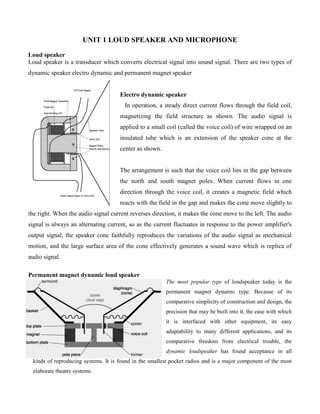
  • 1. UNIT 1 LOUD SPEAKER AND MICROPHONE Loud speaker Loud speaker is a transducer which converts electrical signal into sound signal. There are two types of dynamic speaker electro dynamic and permanent magnet speaker Electro dynamic speaker In operation, a steady direct current flows through the field coil, magnetizing the field structure as shown. The audio signal is applied to a small coil (called the voice coil) of wire wrapped on an insulated tube which is an extension of the speaker cone at the center as shown. The arrangement is such that the voice coil lies in the gap between the north and south magnet poles. When current flows in one direction through the voice coil, it creates a magnetic field which reacts with the field in the gap and makes the cone move slightly to the right. When the audio signal current reverses direction, it makes the cone move to the left. The audio signal is always an alternating current, so as the current fluctuates in response to the power amplifier's output signal, the speaker cone faithfully reproduces the variations of the audio signal as mechanical motion, and the large surface area of the cone effectively generates a sound wave which is replica of audio signal. Permanent magnet dynamic loud speaker The most popular type of loudspeaker today is the permanent magnet dynamic type. Because of its comparative simplicity of construction and design, the precision that may be built into it, the ease with which it is interfaced with other equipment, its easy adaptability to many different applications, and its comparative freedom from electrical trouble, the dynamic loudspeaker has found acceptance in all kinds of reproducing systems. It is found in the smallest pocket radios and is a major component of the most elaborate theatre systems.
  • 2. The PM speaker contains a very light coil of wire affixed to the diaphragm and located concentrically around, within, or in front of the centre of the permanent magnet. The coil (voice coil) is free to move in the field of the magnet. Electrical impulses, varying at an audio rate, are applied to the voice coil by the amplifier. Because these impulses are constantiy changing in amplitude and direction, a changing magnetic field is set up in the voice coil. This field reacts with the constant field of the permanent magnet. The result is that the voice coil moves further into the gap when the fields are opposite and attract, and farther out of the gap when they are alike and repel. This causes an in-and-out movement of the diaphragm; consequently, we obtain sound waves from electrical impulses. The speed at which the coil and diaphragm vibrate depends upon the frequency of the impulses. The distance that the diaphragm moves in and out depends on their amplitude. Piezo electric speakers Piezoelectric speakers have a total different working principle than an electro dynamic speaker. There is no coil, no magnetic field and no large current consumption. The heart of each piezoelectric speaker is a ceramic disc that interacts when it feels a certain voltage difference. An increase of the signal amplitude Vpp (Voltage peak to peak), will result in a larger piezo deformation and result in a larger sound output “Interactingwithvoltagevariations” “MoreVpp createsmoresoundoutput” Piezo ceramic speakers produce sound by the forward and backward movement of a flat membrane. During this movement the membrane creates an air pressure wave in front and at the backside of the membrane. A forward movement will create a slight overpressure at the front side and a slight under pressure at the backside and vice versa. It is therefore important that the front and backside are acoustically isolated from each other to avoid air pressure cancellation and consequently a serious reduction of the sound output. When a speaker is mounted in a panel or in the wall of a housing, the front side is acoustically isolated from the backside
  • 3. Woofers Woofer is the term commonly used for a loudspeaker driver designed to produce low frequency sounds, typically from around 40 hertz up to about a kilohertz or higher. There are two types of low frequency speaker, the commonly known woofer, and the more recent addition the subwoofer. The latter is used for the reproduction of frequencies below those produced by the woofer and it is generally purchased as an add- on to an existing system. The low frequencies speaker provides the bass of any hi-fi system. Its sole purpose is to reduce the low frequency notes of the program source. The prime requisite for low frequency reproduction is a large diaphragm the larger the better. In addition to large size, the diaphragm must be of fairly heavy construction Light diaphragms just can't hold up under the vibrations encountered under the lower audio ranges. A woofer must be able to vibrate back and forth very easily i.e have high compliance. One way to accomplish this is to have the diaphragm loosely connected to the frame. The gasketing that holds the periphery of diaphragm to the frame basket is fastened so that it barely keeps the diaphragm from slipping loose. Rather than the loose suspension system, the cone is supported by a very flexible material so that it can be moved very easily by the voice coil. The suspension is tight hut the sine wave at the diaphragm edge is made very flexible. The large speakers have more extended lows, the smaller ones more extended highs. A woofer must also have a large voice coil to handle considerable heat. The larger the voice coil, the more the current produced by the amplifier output circuit and, therefore, the more the power the woofer can handle. Finally, a strong magnet can be of great help to move the heavy voice coil and cone assembly too well. The better the woofer, the heavier the magnet assembly (unless it's ceramic). Tweeters A tweeter is a loudspeaker designed to produce high audio frequencies, typically from around 2,000 Hz to 20,000 Hz. Some tweeters can manage response up to 65 kHz.Nearly all tweeters are electro-dynamic drivers, using a voice coil suspended within a fixed magnetic field. These designs operate by applying current from the output of an amplifier circuit to a coil of wire, called a voice coil. The voice coil produces a varying magnetic field, which works against the fixed magnetic field of a magnet around which the cylindrical voice coil is suspended, forcing the voice coil and the diaphragm attached to it to move. This mechanical movement exactly resembles the waveform of the electronic signal supplied from the amplifier's output to the voice coil. Since the coil is attached to a diaphragm,
  • 4. the vibratory motion of the voice coil transmits to the diaphragm; the diaphragm in turn vibrates the air thus creating air motions or audio waves, which we hear as high sounds. There are two main types of high frequency speakers; the well-known tweeter and the more recent super tweeter. Super tweeters can be add-ons or they can be integral with the system. Six basic high-frequency speakers (tweeters) exist. (i) The cone is a physically disincentive version of the woofer. (ii) The dome, so called because of its dome-shaped diaphragm. (iii) The horn, so named because it is a horn. (iv) The Heil air-motion transformer which uses the principle of lever in its operation, named after its inventor, Dr. Oskar Heil. (v) High polymer molecular-film tweeter, uses the piezoelectric effect for its principle of operation (used exclusively by Pioneer). (vi) The electrostatic tweeter works on the principle of attraction or repulsion between two metal plates. Types of tweeters Cone tweeter Cone tweeters have the same basic design and form as a woofer with optimizations to operate at higher frequencies. The optimizations usually are:  a very small and light cone so it can move rapidly;  cone materials chosen for stiffness (e.g., ceramic cones in one manufacturer's line), or good damping properties (e.g., silk or coated fabric) or both;  the suspension (or spider) is stiffer than for other drivers—less flexibility is needed for high frequency reproduction;  small voice coils (3/4 inch is typical) and light (thin) wire, which also helps the tweeter cone move rapidly. Cone tweeters are relatively cheap, but do not have the dispersion characteristics of domes. Thus they are routinely seen in low cost applications such as factory car speakers, shelf stereo systems, and boom boxes. Cone tweeters can also be found in older stereo hi-fi system speakers designed and manufactured before the advent of the dome tweeter. They are now a rare sight in modern hi-fi usage.
  • 5. Dome tweeters A dome tweeter is constructed by attaching a voice coil to a dome, which is attached to the magnet or the top plate via a low compliance suspension. These tweeters typically do not have a frame or basket, but a simple front plate attached to the magnet assembly. Dome tweeters are categorized by their voice coil diameter. The majority of dome tweeters presently used in hi-fi speakers are 25 mm (1 in) in diameter. A variation is the ring radiator in which the 'suspension' of the cone or dome becomes the major radiating element. These tweeters have different directivity characteristics when compared to standard dome tweeters. Horn tweeters A horn tweeter is any of the above tweeters coupled to a flared or horn structure. Horns are used for two purposes — to control dispersion, and to couple the tweeter diaphragm to the air for higher efficiency. The tweeter in either case is usually termed a compression driver and is quite different from more common types of tweeters (see above). Properly used, a horn improves the off-axis response of the tweeter by controlling (i.e., reducing) the directivity of the tweeter. It can also improve the efficiency of the tweeter by coupling the relatively high acoustic impedance of the driver to the lower impedance of the air. The larger the horn, the lower the frequencies at which it can work, since large horns provide coupling to the air at lower frequencies. There are different types of horns, including radial and constant directivity (CD). Horn tweeters may have a somewhat 'different' sonic signature than simple dome tweeters. Poorly designed horns, or improperly crossed-over horns, have predictable problems in the accuracy of their output, and the load that they present to the amplifier. Perhaps
  • 6. concerned about the image of poorly designed horns, some manufacturers use horn loaded tweeters, but avoid using the term. Their euphemisms include "elliptical aperture" "Semi-horn" and "Directivity controlled". These are, nonetheless, a form of horn loading. Microphones Microphones are a type of transducer - a device which converts energy from one form to another. Microphones convert acoustical energy (sound waves) into electrical energy (the audio signal). Different types of microphone have different ways of converting energy but they all share one thing in common: The diaphragm. This is a thin piece of material (such as paper, plastic or aluminium) which vibrates when it is struck by sound waves. In a typical hand-held mic like the one below, the diaphragm is located in the head of the microphone. When the diaphragm vibrates, it causes other components in the microphone to vibrate. These vibrations are converted into an electrical current which becomes the audio signal. Dynamic Microphone Dynamic microphones are versatile and ideal for general-purpose use. They use a simple design with few moving parts. They are relatively strong and flexible to rough handling. They are also better suited to handling high volume levels, such as from certain musical instruments or amplifiers. They have no internal amplifier and do not require batteries or external power. Working Principle When a magnet is moved near a coil of wire an electrical current is generated in the wire. Using this electromagnet principle, the dynamic microphone uses a wire coil and magnet to create the audio signal. The diaphragm is attached to the coil. When the diaphragm vibrates in response to incoming sound waves, the coil moves backwards and forwards past the magnet. This creates a current in the coil which is channeled from the microphone along wires.
  • 7. Condenser Microphones Condenser or capacitor, an electronic component which stores energy in the form of an electrostatic field. The use of condenser micro phone is to convert acoustical energy into electrical energy. Condenser microphones require power from a battery or external source. The resulting audio signal is stronger signal than that from a dynamic. Condensers also tend to be more sensitive and responsive than dynamics, making them well-suited to capturing subtle nuances in a sound. They are not ideal for high-volume work, as their sensitivity makes them prone to distort. A capacitor has two plates with a voltage between them. In the condenser mic, one of these plates is made of very light material and acts as the diaphragm. The diaphragm vibrates when struck by sound waves, changing the distance between the two plates and therefore changing the capacitance. Specifically, when the plates are closer together, capacitance increases and a charge current occurs. When the plates are further apart, capacitance decreases and a discharge current occurs. A voltage is required across the capacitor for this to work. This voltage is supplied either by a battery in the mic or by external phantom power. Carbon Microphone The carbon microphone, also known as carbon button microphone, button microphone, or carbon transmitter,It consists of two metal plates separated by granules of carbon. One plate is very thin and faces outward, acting as a diaphragm. When sound waves strike this plate, the pressure on the granules changes, which in turn changes the electrical resistance between the plates. Higher pressure lowers the resistance as the granules are pushed closer together. As a steady direct current is passed between the plates, the varying resistance results in a modulation of the current at the same frequency of the impinging sound waves. In telephony, this signal is directly passed through a telephone system to the central office, or it is electronically amplified in other sound systems, such as a public address system or a recording device. The frequency response of the carbon microphone, however, is limited to a narrow range, and the device produces significant electrical noise.
  • 8. Limitations of carbon microphone One disadvantage of carbon microphones is that of a constant BACKGROUND HISS (hissing noise)which results from random changes in the resistance between individual carbon granules. Other disadvantages are reduced sensitivity and distortion that may result from the granules packing or sticking together. The carbon microphone also has a limited frequency response. Still another disadvantage is a requirement for an external voltage source. The disadvantages, however, are offset by advantages that make its use in military applications widespread. It is lightweight, rugged, and can produce an extremely high output. CRYSTAL MICROPHONE: The crystal microphone uses the PIEZO ELECTRIC EFFECT of Rochelle salt, quartz, or other crystalline materials. This means that when mechanical stress is placed upon the material, a voltage electromagnetic force (EMF) is generated. Since Rochelle salt has the largest voltage output for a given mechanical stress, it is the most commonly used crystal in microphones. In figure A the crystal is mounted so that the sound waves strike it directly. In figure B a diaphragm that is mechanically linked to the crystal so that the sound waves are indirectly coupled to the crystal. Piezo electric speakers WIRELESS MICROPHONE: A wireless microphone, as the name implies, is a microphone without a physical cable connecting it directly to the sound recording or amplifying equipment with which it is associated. Also known as a radio microphone, it has a small, battery-powered radio transmitter in the microphone body, which transmits the audio signal from the microphone by radio waves to a nearby receiver unit, which recovers the audio. The other audio equipment is connected to the receiver unit by cable. Wireless
  • 9. microphones are widely used in the entertainment industry, television broadcasting, and public speaking to allow public speakers, interviewers, performers, and entertainers to move about freely while using a microphone to amplify their voices. There are many different standards, frequencies and transmission technologies used to replace the microphone's cable connection and make it into a wireless microphone. They can transmit, for example, in radio waves using UHF or VHF frequencies, FM, AM, or various digital modulation schemes. Some low cost models use infrared light. Infrared microphones require a direct line of sight between the microphone and the receiver, while costlier radio frequency models do not. ADVANTAGES AND DISADVANTAGES The advantages are:  Greater freedom of movement for the artist or speaker.  Avoidance of cabling problems common with wired microphones, caused by constant moving and stressing the cables.  Reduction of cable "trip hazards" in the performance space The disadvantages are:  Sometimes limited range (a wired balanced XLR microphone can run up to 300 ft or 100 meters). Some wireless systems have a shorter range, while more expensive models can exceed that distance.  Possible interference with or, more often, from other radio equipment or other radio microphones, though models with many frequency-synthesized switch-selectable channels are now plentiful and cost effective.  Operation time is limited relative to battery life; it is shorter than a normal condenser microphone due to greater drain on batteries from transmitting circuitry, and from circuitry giving extra features, if present.  Noise or dead spots.  Limited number of operating microphones at the same time and place, due to the limited number of radio channels.
  • 10. Characteristics of Microphones There are many types of microphones available. Each has certain advantages and disadvantages. Hence the selection of microphones depends upon the certain characteristics as below: (1) Output level; (2) Frequency response; (3) Output impedance and (4) Directivity. (1) Output level: - The output level of a microphone governs the amount of amplification that must be available for use with the microphone. The output level of microphone is usually given in dB preceded by a minus sign. The minus sign means that the output level is so many dB below the reference level of 1milliwatt for a specified sound pressure. (2) Frequency response: - The frequency response of a microphone is a rating of the fidelity of relative output voltage which results from sound waves of different frequencies. The simplest way to find a complete picture of the frequency response characteristics of a microphone is to plot a curve of its output voltage v/s input frequency. Since good microphones are relatively flat over their range, it is often considered sufficient to specify the range over which their output does not vary more than ±1-2 dB. (3) Output impedance: - A microphone, like any other component with electrical i/p of o/p, has a value of impedance. When a microphone is connected to an amplifier, a complete circuit is formed and electric current flows whenever a sound causes the microphone to generate an electrical voltage. For most high quality microphones impedance is low, a few ohms ranging upto a hundred ohms or so. The importance of microphone impedance is not a matter of the precise value but of the ability of the microphone and the recorder to be matched together. High impedance microphones must be connected must be connected into a recorder with high impedance input, otherwise both the signal amplitude and the frequency range will be adversely affected. Directional Properties Every microphone has a property known as directionality. This describes the microphone's sensitivity to sound from various directions. Some microphones pick up sound equally from all directions, others pick up sound only from one direction or a particular combination of directions. The types of directionality are divided into three main categories: 1. Omnidirectional Picks up sound evenly from all directions (omni means "all" or "every"). 2. Unidirectional Picks up sound predominantly from one direction. This includes cardioid and hypercardioid microphones (see below). 3. Bidirectional Picks up sound from two opposite directions. To help understand a the directional properties of a particular microphone, user manuals and promotional material often include a graphical representation of the microphone's directionality. This graph is called a polar pattern. Some typical examples are shown below.
  • 11. Omnidirectional Captures sound equally from all directions. Uses: Capturing ambient noise; Situations where sound is coming from many directions; Situations where the mic position must remain fixed while the sound source is moving. Notes:  Although omnidirectional mics are very useful in the right situation, picking up sound from every direction is not usually what you need. Omni sound is very general and unfocused - if you are trying to capture sound from a particular subject or area it is likely to be overwhelmed by other noise. Cardioid Cardioid means "heart-shaped", which is the type of pick-up pattern these mics use. Sound is picked up mostly from the front, but to a lesser extent the sides as well. Uses: Emphasizing sound from the direction the mic is pointed whilst leaving some latitude for mic movement and ambient noise. Notes:  The cardioid is a very versatile microphone, ideal for general use. Handheld mics are usually cardioid.  There are many variations of the cardioid pattern (such as the hypercardioid below). Hypercardioid This is exaggerated version of the cardioid pattern. It is very directional and eliminates most sound from the sides and rear. Due to the long thin design of hypercardioids, they are often referred to as shotgun microphones. Uses: Isolating the sound from a subject or direction when there is a lot of ambient noise; Picking up sound from a subject at a distance. Notes:  By removing all the ambient noise, unidirectional sound can sometimes be a little unnatural. It may help to add a discreet audio bed from another mic (i.e. constant background noise at a low level).  You need to be careful to keep the sound consistent. If the mic doesn't stay pointed at the subject you will lose the audio.  Shotguns can have an area of increased sensitivity directly to the rear. Bidirectional Uses a figure-of-eight pattern and picks up sound equally from two opposite directions. Uses: As you can imagine, there aren't a lot of situations which require this polar pattern. One possibility would be an interview with two people facing each other (with the mic between them).