(PRIYA) Rajgurunagar Call Girls Just Call 7001035870 [ Cash on Delivery ] Pun...
Eecb351 exp 8 ask fsk
1. COMMUNICATION SYSTEM LABORATORY
EXPERIMENT 8: AMPLITUDE SHIFT KEYING and FREQUENCY SHIFT KEYING
A. OBJECTIVE OF EXPERIMENT
1. To examine the amplitude shift keying (ASK) and frequency shift keying (FSK) in digital
techniques.
2. To investigate the generation and reception of ASK and FSK process.
B. EQUIPMENT REQUIRED
1. Emona Telecoms –Trainer 101
2. Oscilloscope and Patch leads
3. Dual Channel Oscilloscope
C. SUMMARY OF THEORY
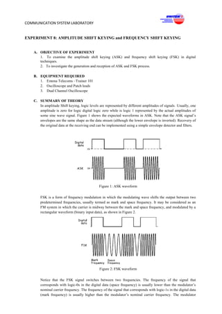
In amplitude Shift keying, logic levels are represented by different amplitudes of signals. Usually, one
amplitude is zero for logic digital logic zero while is logic 1 represented by the actual amplitudes of
some sine wave signal. Figure 1 shows the expected waveforms in ASK. Note that the ASK signal’s
envelopes are the same shape as the data stream (although the lower envelope is inverted). Recovery of
the original data at the receiving end can be implemented using a simple envelope detector and filters.
Figure 1: ASK waveform
FSK is a form of frequency modulation in which the modulating wave shifts the output between two
predetermined frequencies, usually termed as mark and space frequency. It may be considered as an
FM system in which the carrier is midway between the mark and space frequency, and modulated by a
rectangular waveform (binary input data), as shown in Figure 2.
Figure 2: FSK waveform
Notice that the FSK signal switches between two frequencies. The frequency of the signal that
corresponds with logic-0s in the digital data (space frequency) is usually lower than the modulator’s
nominal carrier frequency. The frequency of the signal that corresponds with logic-1s in the digital data
(mark frequency) is usually higher than the modulator’s nominal carrier frequency. The modulator
2. COMMUNICATION SYSTEM LABORATORY
doesn’t output a signal at the carrier frequency, hence the reference here to it as being “nominal”
carrier frequency. The FSK generation can be handled by conventional FM modulator circuits and the
voltage-controlled oscillator (VCO) is commonly used. Similarly, demodulation can be handled by
conventional FM demodulators such as FSK the zero crossing detector and the phase-locked loop.
Alternatively, if the FSK signal is passed through a sufficiently selective filter, the two sine waves that
make it up can be individually picked out. One of the reasons for using FSK is to take advantage of the
relative noise immunity that FM enjoys over AM. Recall that noise manifests itself as variations in the
transmitted signal’s amplitude. These variations can be removed by FM/FSK receivers (by a circuit
called a limiter) without adversely affecting the recovered message.
D. PROCEDURE
Part A – Generating an ASK signal
1. Gather a set of the equipment listed above.
2. Set the scope’s Trigger Source control to the EXT position.
3. Set the scope’s Trigger Source Coupling control to the HF REJ position.
4. Set the scope’s Channel 1 and Channel 2 Input Coupling controls to the DC position.
5. Set the scope’s Timebase control to the 1ms/div position.
6. Connect the set-up shown in Figure 3 below. Note: Insert the black plugs of the oscilloscope leads
into a ground (GND) socket.
7. Locate the VCO module and set its Frequency Adjust control to about the middle of its travel.
8. Set the VCO module’s Range control to the HI position.
Ideally, the carrier frequency should be much higher than the bit-rate of the digital signal (which is
determined by the Sequence Generator module’s clock frequency in this set-up). The next part of
the experiment gets you to set the carrier to a more appropriate frequency (about 100 kHz). In the
process, the Dual Analog Switch module’s output will look more like a conventional ASK signal.
9. Monitor and compare the ASK signal output and digital signal output.
Figure 3
3. COMMUNICATION SYSTEM LABORATORY
Part B – Demodulating an ASK signal using an envelope detector
As ASK is really just AM (with a digital message instead of speech or music), it can be recovered using
any of AM demodulation schemes. The next part of the experiment lets you do so using an envelope
detector.
1. Locate the Tunable Low-pass Filter module and turn its Gain control fully clockwise.
2. Turn the Tunable Low-pass Filter module’s Cut-off Frequency Adjust control fully clockwise.
3. Set-up as shown in Figure 4 below.
4. Refer Figure 3 for the ASK generation.
Note: The left most modules have been left off to fit the drawing on the page. The ASK generation
and demodulation parts of the set-up can be represented by the block diagram in Figure 4. The
rectifier on the Utilities module and the Tunable Low-pass filter module are used to implement
an envelope detector to recover the digital data from the ASK signal.
Figure 4
Part C – Restoring the recovered digital signal using a comparator
1. Set-up the connection for block diagram shown in Figure 5.
2. Refer Figure 2 and Figure 3 for ASK generation and envelope detection.
3. Set the Variable DCV module’s Variable DC control to about the middle of its travel. Compare the
signals. If they’re not the same, vary the Variable DCV module’s Variable DC control until they
are.
4. Monitor the digital input signal and the restored signal.
4. COMMUNICATION SYSTEM LABORATORY
Figure 5
Part D – Generating a FSK signal
1. Set the scope’s Trigger Source control to the EXT position.
2. Set the scope’s Trigger Source Coupling control to the HF REJ position.
3. Set the scope’s Channel 1 and Channel 2 Input Coupling controls to the DC position.
4. Locate the VCO module and set its Gain control to about half its travel.
5. Set the VCO module’s Frequency Adjust control to about a quarter of its travel (about the position
of the number 9 on a clock face).
6. Set the VCO module’s Range control to the LO position.
7. Locate the Sequence Generator module and set its dip-switches to 00. Tip: To do this, push both
switches up.
8. Connect the set-up shown in Figure 6 below.
Note: Insert the black plugs of the oscilloscope leads into a ground (GND) socket.
Figure 6
9. Set the scope’s Timebase control to the 0.5ms/div position.
10. Set the scope’s Mode control to the DUAL position to view the Sequence Generator module’s
output and the FSK signal out of the Voltage Controlled Oscillator module.
11. Compare and monitor the Ch 1 and Ch 2 output signals. Determine the mark and space frequency.
5. COMMUNICATION SYSTEM LABORATORY
Note: If the sine waves in the FSK signal roll too much, turn the VCO module’s Frequency Adjust
control a little left or right to stabilize it.
Part E – Demodulating an FSK signal using filtering and an envelope detector
FSK is really just FM; it can be recovered using any of the FM demodulation schemes. However, as
the FSK signal switches back and forth between just two frequencies we can use a method of
demodulating it that cannot be used to demodulate speech encoded FM signals. The next part of the
experiment lets you do this.
1. Turn the VCO module’s Frequency Adjust control to about the position of the number 2 on a clock
face.
2. Locate the Tunable LPF module and turn its Cut-off Frequency Adjust control fully clockwise.
3. Turn the Tunable LPF’s Gain control fully clockwise.
4. Set-up as shown in Figure 7.
5. For FSK generation: Follow the Figure 6.
6. Compare and monitor the digital signal and the filter’s output. These should be visible as Ch.1 and
Ch.2 on the scope display.
Note: Remember that the dotted lines show leads already in place. Also, the left most modules have
been cut-off to fit the drawing on the page. The FSK generation and demodulation parts of the set-
up can be represented by the block diagram in Figure 6 below. The Low-pass filter module is used
to pick out one of the FSK signal’s two sine waves and the RECTIFIER and BASEBAND LPF
combination form the envelope detector to complete the FSK signal’s demodulation.
VCO RECTIFIER
sine
IN
out
IN
out
Figure 7
Part F – Restoring the recovered data using a comparator
This experiment shows that the comparator is a useful circuit for restoring distorted digital signals.
The next part of the experiment lets you use a comparator to clean-up the demodulated FSK signal.
1. Set-up as shown in Figure 8 below.
2. For FSK generation and FSK demodulation: Follow the Figure 6 and Figure 7.
3. Note the amplitude of the filtered signal into the COMPARATOR. It varies from about 0 volts to a
maximum level.
4. Set the Variable DCV module’s Variable DC voltage output to a level which is half of the level. This
signal is setting the threshold voltage of the COMPARATOR.
6. COMMUNICATION SYSTEM LABORATORY
5. Compare and monitor the original digital signal and the recovered digital signal out of the
COMPARATOR. If they’re not the same vary the Variable DCV module’s Variable DC control
slightly until they are.
Figure 8
E. RESULTS AND CALCULATION
1. Observe and compare the ASK signal output and digital signal output.
2. Observe and compare the original signal and recovered digital signal.
3. Monitor the Ch 1 and Ch2 output signals for Figure 5
4. Compare and monitor the Ch 1 and Ch 2 output signals for Figure 6
5. Compare and monitor the digital signal and the filter’s output for Figure 7
6. Compare and monitor the original digital signal and the recovered digital signal out of the
COMPARATOR in Figure 8
F. DISCUSSION
1. What features of the ASK signal suggests that it’s an AM signal?
2. Why is the recovered digital signal not a perfect copy of the original?
3. What can be used to “clean-up” the recovered digital signal?
4. How does the comparator turn the slow rising voltages of the recovered digital signal into sharp
transitions?
5. Can ASK/FSK modulation technique be used for high data rate long range wireless transmission?
Explain why?