
Recommended
More Related Content
What's hot
What's hot (20)
Similar to Techno-Economics of Rooftop Solar Photovoltaic Systems in India
Similar to Techno-Economics of Rooftop Solar Photovoltaic Systems in India (20)
Recently uploaded
Recently uploaded (20)
Techno-Economics of Rooftop Solar Photovoltaic Systems in India
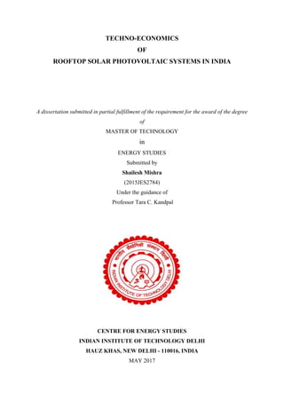
- 1. TECHNO-ECONOMICS OF ROOFTOP SOLAR PHOTOVOLTAIC SYSTEMS IN INDIA A dissertation submitted in partial fulfillment of the requirement for the award of the degree of MASTER OF TECHNOLOGY in ENERGY STUDIES Submitted by Shailesh Mishra (2015JES2784) Under the guidance of Professor Tara C. Kandpal CENTRE FOR ENERGY STUDIES INDIAN INSTITUTE OF TECHNOLOGY DELHI HAUZ KHAS, NEW DELHI - 110016, INDIA MAY 2017
- 2. i Certificate The work presented in this report has been carried out by me towards the partial fulfilment of the requirements for the award of MASTER OF TECHNOLOGY in Energy Studies, Indian Institute of Technology Delhi. The materials taken from other sources have been acknowledged. The results presented in this work have not been submitted in part or full to any other university for the award of degree/diploma. Shailesh Mishra 2015JES2784 The thesis entitled, “Techno-Economics of Rooftop Solar Photovoltaic Projects in India” submitted by Shailesh Mishra (2015JES2784) towards the partial fulfilment of the requirements for the award of MASTER OF TECHNOLOGY in Energy Studies, Indian Institute of Technology Delhi, is a record of the work carried out by him under my guidance and supervision. Dr. Tara C. Kandpal Professor Centre for Energy Studies IIT Delhi – 110 016
- 3. ii Acknowledgements I would like to take this opportunity to express my sincere gratitude to my guide Professor Tara C. Kandpal for his earnest support, prompt and excellent direction, everlasting encouragement, and inspiration bestowed upon me throughout my project work. Without his continuous support and critical analysis, the present work would not have been possible. I am also thankful to Dr. K.A. Subramanian for his efforts in smoothing out the administrative processes and consistent support in his capacity as M. Tech. coordinator. I am also thankful to Prof. Viresh Dutta, the Head, Centre for Energy Studies and all other faculty members’ of CES for their positive insights and constructive feedbacks during various courses they taught, project evaluations and the exciting past two years. I would also like to express my profound appreciation to Mr. Ashish Sharma, Mr. Tarun Kumar Aseri and Mr. Saurabh Singhal for their inputs, feedbacks and reviews and all other helping hands that were instrumental in many ways in completion of my project. My thanks are also due to my fellow classmates for embracing me as a member of their dynamic team, and also for their support and encouragement, without which the two years journey, and of course the learning process would not have been as productive and enjoyable. Finally, I would like to thank my family for their encouragement and blessings. Last but not the least; I would like to acknowledge the tireless support, understanding, patience and hardships faced by none other but my wife Ratnesh Mishra and our lovely kids Ajitesh and Anika, for allowing me to carry forward my higher studies. My sincere thanks and profound appreciation to my elder brother Tapas Gupta for his wonderful guidance and unshakable and inspirational support, without which I would not have achieved whatever little I have done so far. I am equally grateful to Rajneesh Pandey and the whole family members for their generous support and painstaking efforts to take care of my wife and kids during my absence. Finally, I remain grateful to all my friends and good-wishers, who always gave me moral support to accomplish my goal. Shailesh Mishra 2015JES2784
- 4. iii Abstract In this study, a preliminary attempt has been made to (i) assess the potential of rooftop solar PV power generation in India and (ii) evaluate its financial feasibility. For this, rooftop PV potential of 21 cities in India has been estimated which is further extrapolated to give the overall potential of urban buildings in the country under residential, commercial, institutional and industrial categories. Further, estimation of annual energy delivery and the levelized cost of electricity produced by the rooftop PV system have been made with the help of System Advisor Model (SAM). The value of LCOE for a 5 kW system varies from ₹ 6.47/kWh (Jaisalmer) to ₹ 8.63/kWh (Kohima) while the same are marginally different for a 2 kW system varying from ₹ 6.51/kWh to ₹ 8.69/kWh. An attempt has also been made to review the electricity tariff for different categories of consumers’ e.g. domestic, commercial, industrial and agricultural in all states /UTs and also their policies for promoting rooftop solar PV. Net-metering provision for the implementation of rooftop solar PV has already been notified by all states/UTs. However, only 13 states have implemented the Feed-in Tariff (FiT) mechanism to promote rooftop solar PV systems. Eight of these states have provision for accelerated depreciation and accordingly, the FiT is somewhat lower. In some of the states having slab based pricing, above a certain monthly consumption of electricity, the LCOE for rooftop solar PV is found to be lower than the grid electricity tariff indicating the potential for rooftop solar PV systems being competitive with grid electricity. The values of payback period, net present value (NPV), internal rate of return (IRR), minimum feed-in tariff (FiTmin) required to reach breakeven and the extent of incentives required for rooftop solar PV (RTSPV) systems to be financially viable have also been estimated. It is observed that, for all locations considered in this study, the values of LCOE delivered by RTSPV systems are higher than that of the average power purchase cost (APPC) of conventional fossil fuel based electricity. Support in terms of financial/fiscal incentives for promotion of RTSPV in India is therefore recommended at this stage.
- 5. iv Contents Certificate ................................................................................................................................. i Acknowledgements ................................................................................................................. ii Abstract................................................................................................................................... iii List of Figures........................................................................................................................ vii List of Tables ........................................................................................................................ viii Nomenclature ...........................................................................................................................x Chapter 1: Introduction and Literature Review...................................................................1 1.1 Relevance and Need for Harnessing Renewable Energy ...................................................1 1.2 Solar Photovoltaic Electricity Generation in India.............................................................2 1.3 Design Details of a Typical Rooftop Solar PV System......................................................3 1.4 Literature Review...............................................................................................................5 1.4.1 Technical feasibility and challenges..........................................................................5 1.4.2 Estimation of rooftop solar PV potential...................................................................6 1.4.3 Economics and policy measures................................................................................6 1.5 Objectives of the study.......................................................................................................7 Chapter 2: Estimation of the Potential of Rooftop Solar PV in India ................................8 2.1 Factors Used for Estimating Usable Roof Area for PV Installation ..................................9 2.1.1 Shading from adjacent buildings /trees: ....................................................................9 2.1.2 Clearance between wall and PV arrays .....................................................................9 2.1.3 Space for other items (such as a solar water heating system) on the roof...............10 2.1.4 Space required by water storage tank(s)..................................................................10 2.1.5 Space required by staircase (s) ................................................................................10 2.1.6 Inter-row spacing to avoid self-shading losses and cleaning space required for rooftop PV systems...........................................................................................................11 2.1.7 Shading losses due to railings..................................................................................11 2.2 Estimation of rooftop solar PV potential for urban settlements in India..........................15 2.3 Results and Discussion.....................................................................................................18 Chapter 3: Estimation of Levelized Cost of Electricity (LCOE) Delivered by Rooftop Solar PV Plants at Different Locations in India .................................................................19 3.1 Estimation of Annual Energy Delivered (AED) and Levelized Cost of Electricity ........19 3.2 Sensitivity Analysis of LCOE Delivered by Rooftop Solar PV Systems ........................22
- 6. v 3.3 Review and Analysis of Rooftop Solar PV Related Policies in Different States of India ................................................................................................................................................24 Chapter 4: Financial Feasibility of Rooftop Solar PV Systems and Incentives Required for Their Promotion...............................................................................................................27 4.1 Financial Feasibility of Rooftop Solar PV Systems.........................................................27 4.1.1 Estimates of NPV, TSP, TDP and IRR.......................................................................28 4.1.2 Minimum feed-in tariff (FiT) required for financial viability.................................29 4.2 Estimation of Required Level of Incentives for Promotion of Rooftop Solar PV Systems ...............................................................................................................................................31 4.2.1 Introduction ...................................................................................................................31 4.3 Different Types of Incentives...........................................................................................32 4.3.1 Capital subsidy and viability gap funding (VGF) ...................................................33 4.3.2 Soft loan and interest subsidy..................................................................................34 4.3.3 Accelerated depreciation .........................................................................................36 4.3.4 Carbon mitigation benefits – certified emission reduction unit ..............................38 4.3.5 Investment tax credit ...............................................................................................39 Chapter 5: Conclusions and Recommendations .................................................................41 5.1 Conclusions ......................................................................................................................41 5.2 Recommendations ............................................................................................................43 References...............................................................................................................................44 Appendices..............................................................................................................................60 Appendix – A Land use pattern and percentage share of different categories of buildings ....61 Appendix –B Extent of clearance required between wall and PV arrays................................65 Appendix –C Space required by staircase ...............................................................................66 Appendix –D Shading due to railings and minimum height from the rooftop level for installing PV arrays..................................................................................................................67 Appendix –E Buildings with concrete roof and their percentage under different building categories .................................................................................................................................69 Appendix –F Average number of stories for residential buildings in India ............................70 Appendix –G Average annual GHI and ambient temperature of different cities in India.......71 Appendix –H Estimates for annual energy delivered by rooftop PV and corresponding values of LCOE...................................................................................................................................73 Appendix –I Relevant policies for promotion of rooftop solar PV in various states in India .75 Appendix –J Summary of available feed-in tariff (FiT) in various states of India..................77
- 7. vi Appendix –K Tariff for different categories of consumers in various states...........................78
- 8. vii List of Figures Figure 1.1: Cumulative installed capacity of solar PV based electricity generation in India...2 Figure 1.2: Schematic Diagram of a Rooftop Solar PV system ...............................................4 Figure 2.1: Steps involved in assessing the potential of rooftop solar PV in India..................8 Figure 2.2: Schematic flow chart depicting steps involved in the estimation of rooftop solar PV potential in India ................................................................................................................13 Figure 3.1: Methodology adopted for estimation of annual energy delivered and LCOE .....19 Figure 3.2: Feed-in tariff (FiT) with and without AD benefits in various states....................25 Figure 3.3: Feed-in tariff (FiT) in 5 states ..............................................................................26 Figure 4.1: A schematic of the approach adopted for studying the effect of incentives on LCOE delivered by rooftop solar PV systems.........................................................................33 Figure B.1: A schematic showing rooftop and the clearance on it.........................................65
- 9. viii List of Tables Table 1.1: Relative strengths and limitations of ground mounted solar PV systems................3 Table 1.2: Relative strengths and limitations of rooftop Solar PV systems .............................4 Table 2.1: Estimates of shading losses due to adjacent building structures and trees ..............9 Table 2.2: Factors internalized in estimating usable roof area for PV installations ...............12 Table 2.3: Potential estimation of rooftop solar PV based on assumptions made by TERI (2014) and variations observed during the present study ........................................................13 Table 2.4: Total occupied urban buildings, their % share of under different building categories, and total rooftops available for solar PV implementation.....................................16 Table 2.5: Criteria assumed for deciding number of floors in a building based on population density of cities ........................................................................................................................17 Table 3.1: Values of input parameters used in this study .......................................................21 Table 3.2: Estimates for annual energy delivered by RTSPV systems, their corresponding LCOE and APPC of respective locations ................................................................................22 Table 3.3: Input parameters for LCOE estimation and probable reasons for variance...........23 Table 3.4: Estimates for sensitivity of LCOE to 1% change in input parameters ..................24 Table 4.1: Estimates for TSP, TDP, NPV and IRR (5 kW system)...........................................29 Table 4.2: Estimates for minimum FiT required for breakeven (i.e. FiT at which NPV=0) when capital subsidy or lower rate of interest on capital is provided (5 kW) .........................30 Table 4.3: Estimates for the minimum value of feed-in tariff when a capital subsidy equivalent to CO2 emission mitigation benefits, lower interest rate loan along with a capital grant (5 kW).............................................................................................................................31 Table 4.4: Extent of VGF required for LCOE to be equal to APPC.......................................34 Table 4.5: Estimation of annual interest subsidy and equivalent cost to the government ......36 Table 4.6: Estimates for AD, CERU and ITC benefits for achieving target value of APPC..40 Table 5.1: The extent of incentives required to make rooftop PV market competitive..........42 Table A1: Land use pattern and percentage share (weighted average of 21 cities) of different buildings...................................................................................................................................61 Table A2: Provision of ground coverage for different building categories in Building Bye- Laws.........................................................................................................................................62 Table A3: Reported field level efficiencies of rooftop solar PV systems...............................63 Table A4: Sample cities considered for this study and their respective climatic zone...........64 Table C1: Requirements for staircase for different types of buildings...................................66
- 10. ix Table C2: Roof area required by staircase (s) for different categories of buildings..............66 Table D1: Estimates for shadow length at different time of the day ......................................67 Table E1: Number of total occupied urban buildings (all may not have concrete roof) and their percentage share under different building categories......................................................69 Table F1: Average number of stories for residential buildings in India.................................70 Table G1: Average annual GHI and ambient temperature of different cities in India ...........71 Table H1: Estimation of annual energy delivered and corresponding values of LCOE for different capacity of plants at various locations ......................................................................73 Table I1: Relevant policies for promotion of rooftop solar PV in various states in India......75 Table J1: Summary of available feed-in tariff (FiT) in various states of India......................77 Table K1: State wise electricity tariff for domestic consumers..............................................78 Table K2: State wise electricity tariff for commercial consumers .........................................80 Table K3: State wise electricity tariff for Industrial consumers.............................................82
- 11. x Nomenclature Acronyms used in present study ACOM Annual Operation and Maintenance Cost AD Accelerated Depreciation ADB Asian Development Bank APPC Average Power Purchase Cost BOS Balance of System CEA Central Electricity Authority CFA Central Financial Assistance CERC Central Electricity Regulatory Commission CERU Certified Emission Reduction Unit CUF Capacity Utilization Factor FiT Feed -in Tariff GHG Greenhouse Gases (GHG GHI Global Horizontal Irradiance GW Giga Watts (1 GW =109 Watts) IRR Internal Rate of Return ITC Investment Tax Credit JNNSM Jawaharlal Nehru National Solar Mission LCOE Levelized Cost of Electricity MWh Mega Watt hour NPV Net Present Value NREL National Renewable Energy Laboratory PV Photovoltaic RTSPV Rooftop Solar Photovoltaic SAM System Advisor Model SECI Solar Energy Corporation of India TEDA Tamil Nadu Energy Development Agency TERI The Energy and Resources Institute VGF Viability Gap Funding WACC Weighted Average Cost of Capital
- 12. 1 Chapter 1: Introduction and Literature Review 1.1 Relevance and Need for Harnessing Renewable Energy Global energy demand increased rapidly in the 20th century and the same trend is continuing in the 21st century as well (REN21, 2016). A major share of the global energy demand has been met with fossil fuels (REN21, 2016). The extraction, conversion, transmission (transport), distribution and utilization of fossil fuels lead to the release of a variety of environmental pollutants including the CO2 (IRENA, 2016a). Increased concentration of greenhouse gases such as CO2 in the atmosphere has manifested in terms of global warming and many other adverse environmental effects (IRENA, 2016a). Large scale harnessing of renewable energy resources and adoption of energy efficiency and other demand-side management measures are expected to solve this problem. A large number of countries in the world have initiated ambitious programs in this direction and considerable success has been achieved in both harnessing the renewable sources of energy as well as in improving the efficiency of energy utilization. As a consequence, the energy mix is changing on the global scale (REN21, 2016; IRENA, 2016a). By the end of 2015, the total electricity generation from renewables accounted for almost 23.7% of global electricity production (IRENA, 2016a; REN21, 2016). In 2016, the worldwide total installed capacity of electricity generation based on renewable sources of energy (excluding large hydropower and pumped storage) reached 1070 GW (IRENA, 2016b). In India, the installed capacity for electricity generation based on renewable energy resources reached 49.12 GW in 2016 (95.53 GW including large hydro and pumped storage plants) as against a capacity of just 2.31 GW in the year 2000 (IRENA, 2016b). Amongst the various renewable sources of energy, solar energy is expected to play a very important role in view of its decentralized availability in most of the countries of the world. Two distinct technological routes have so far been developed for generating electricity from solar energy. One of the options uses solar energy to produce steam at high temperatures and the same is then used to drive a steam turbine to produce electricity. This solar thermal power generation route has a global installed capacity of 4.87 GW in 2016 (IRENA, 2016b) and is still not cost competitive with the other option for electricity generation based on solar energy. The second option is based on direct conversion of solar energy into electricity using photovoltaic (solar) cells. There has been a substantial cost reduction in producing electricity
- 13. 2 through this photovoltaic power generation route in recent years. The global photovoltaic electricity generation capacity was reportedly 290 GW in 2016 with India having installed capacity of 9.6 GW by the same time (REN21, 2016; IRENA, 2016b). Figure 1.1: Cumulative installed capacity of solar PV based electricity generation in India Source: IRENA (2016b) 1.2 Solar Photovoltaic Electricity Generation in India A time trend of PV based installed capacity for electricity generation in India is presented in Figure 1.1. The solar photovoltaic market in India has grown significantly after the launch of the Jawaharlal Nehru National Solar Mission in 2010, with total installed capacity of over 9658 MW by the end of 2016. JNNSM was launched in 2010 with a target for grid-connected the solar power of 20 GW by 2022 which was further revised to 100 GW by the union cabinet of the Government of India on 17 June 2015 (MNRE, 2015; JNNSM, 2010). This comprises of 40 GW from the rooftop solar scheme and remaining 60 GW from large and medium scale grid connected solar power projects. As indicated above, two approaches can be adopted for photovoltaic generation of electricity- using land based (ground mounted) photovoltaic plants and rooftop PV systems. A discussion on relative strengths and limitations of the two routes is presented in Tables 1.1 and 1.2. 4.8 4.3 10.1 11.5 36.8 562.5 1277.1 2268.9 3059.3 4963.5 9658.2 0 1000 2000 3000 4000 5000 6000 7000 8000 9000 10000 11000 2005 2006 2007 2008 2009 2010 2011 2012 2013 2014 2015 2016 2017 Installedpower(MW) Year
- 14. 3 It is against this background that an attempt to assess the potential of rooftop solar PV power generation in India and evaluation of its techno-economics and extent of incentives required to make rooftop PV economically viable has been made in this study. Table 1.1: Relative strengths and limitations of ground mounted solar PV systems S. No. Strengths Limitations 1 Easy to opt for tracking option i.e. flexibility to tilt and adjust panel orientation for maximum energy generation Urban settings often do not have the required land space 2 Better cooling and lower cell temperatures due to increased air flow around panels and consequently better efficiency and higher energy production Typically more expensive to install due to the cost of frame, solid foundations and concrete footings required for stability to withstand high wind and storms.3 Larger system can be installed as more space is likely to be available on the ground than on the roof 4 Cell cleaning and maintenance is relatively easy Due to increased accessibility, it may be relatively easy to damage and vandalize 1.3 Design Details of a Typical Rooftop Solar PV System A rooftop solar photovoltaic (PV) system, mounted on the roof of a building is an electrical installation that converts solar energy into electricity. This can be used to meet the building’s own energy consumption requirements or, in certain situations, fed back into the electrical grid. Rooftop solar PV systems are distributed electricity generation options, which help to meet a building’s energy needs or provide electricity within an existing distribution network (Mahajan and Aggarwal, 2015).
- 15. 4 Table 1.2: Relative strengths and limitations of rooftop Solar PV systems S.No. Strengths Limitations 1 More suitable for urban settings as exclusive land is not required Relatively difficult to opt for tracking options 2 Installation is typically less expensive as cost incurred in foundation and concrete footings can be avoided Less air flow around panels may result in higher cell temperature 3 Due to limited access, less prone to damage Shadow from adjacent buildings may result in lower energy production 4 The end user is right there at the plant site itself and thus the losses in transmission and distribution of electricity can be reduced. Cell cleaning and maintenance may be relatively difficult 5 Relatively lower gestation period in installation The prevailing bye-laws at the location must have the necessary clarity and should incentivize installation of rooftop PV systems. 6 Self-consumption of solar electricity by end- user at site may help in improved tail-end voltage and reduce the system congestion A rooftop PV system consists of PV panels, mounting frames to secure the modules on the roof, string boxes to connect multiple modules, inverters to convert the direct current (DC) output of the panel into alternating current (AC), batteries to provide energy storage or backup power in case of grid failure, DC switch to isolate the PV panel from inverter, energy meter to record energy uses and indicate system performance and balance of system (BOS) components include racking, electrical cables, switches, enclosures, fuses, ground fault detectors etc. (ADB, 2014). Figure 1.2: Schematic Diagram of a Rooftop Solar PV system PV panel Inverter AC Voltage AC appliances DC Appliances DC Voltage Sun
- 16. 5 In view of the importance of rooftop solar photovoltaic systems in a country like India, it is necessary that the comprehensive information on following aspects is obtained so as to make and implement appropriate strategies for the large-scale diffusion: a) Potential of Rooftop PV generation in the country. b) Levelized cost of electricity delivered by rooftop PV system and the impact of technological and climatic parameters on its value. c) Identification of appropriate regulatory, financial, policy and fiscal measures that can expedite the diffusion of rooftop PV in the country. 1.4 Literature Review 1.4.1 Technical feasibility and challenges Dawn et al. (2016) emphasized on the need to have a single agency responsible for framing and implementing support and promotional measures for solar energy technologies. The writers further noted that the Indian manufacturers are not able to compete with suppliers of foreign products in PV industry. Shukla et al. (2016) analyzed the performance of a 110 kWp a grid connected solar rooftop PV system using Solarigis PV Planner software and observed that amorphous silicon (a-Si) and Cadmium telluride (CdTe) PV cells have above 75% performance ratios under typical weather conditions in Bhopal. Sahoo (2016) highlighted the trends and achievements in the generation of electricity from renewable sources of energy and discussed the recent progress and existing policies and support measures to promote solar energy in India. Kar et al. (2016), some of the key challenges to the solar power development as noted in their study are grid connectivity and unprepared evacuation infrastructure, initial capital investment, lack of financing, regulatory and policy developments, capacity utilization, consumer awareness and acceptance. The study suggested that strategic support measures like skill development, easy access to financing and developing a domestic solar component's manufacturing industry may help in addressing the existing challenges. Sandwell et al. (2016) used a model for comparing PV technologies for rural electrification with grid extension or diesel generation both in terms of the levelized cost and life cycle emission intensity. They further analyzed and suggested that PV generation will dominate the most cost effective hybrid system around 2018.
- 17. 6 Tripathi et al. (2016) stressed upon the need for harnessing renewable energy potential for enhanced energy security, reduced greenhouse gas emissions, and environment-friendly power generation. Kappagantu et al. (2015) presented an analysis of rooftop solar PV system implementation barriers in Puducherry smart grid pilot project. Also, the authors, during their survey with consumers, noted the high upfront cost, lack of awareness about net-metering /gross metering policy implications and long payback period as some of the major concerns in rooftop PV implementation. 1.4.2 Estimation of rooftop solar PV potential Singh and Banerjee (2015) studied the effect of tilt angle on plane-of-array to select an optimum value and estimated the effective sunshine hours, installed capacity of Mumbai as 2190 MW and annual average capacity utilization factor 14.8%. Analysis showed that rooftop solar PV systems if deployed at large scale can provide 12.8–20% of the average daily energy demand and 31–60% of the peak demand in morning hours. TERI (2014) estimated the rooftop solar PV potential for urban settlements in India to be about 352 GW as technical, 210 as economic and 124 GW as market potential. In the present study, an effort has been made to refine the assumptions made in their study. Ramachandra et al. (2011) assessed the solar power potential for India from satellite-derived insolation data and found that nearly 58% part of India receives annual global average insolation of 5kWh/m2 /day or more which offers immense power generation and emission reduction potential. 1.4.3 Economics and policy measures Rohankar et al. (2016) reaffirmed the financial feasibility of solar power projects under various policy initiatives and support measures by Indian government and reduction in the tariff of solar power from ₹ 17/kWh in 2010 to less than ₹ 6 /kWh in 2015. However, cautioned that significantly lower tariff than the benchmarked tariff of ₹ 7 (US $ 0.107), may cause a problem to the sustainability of the project. Yenneti (2016) noted that the Feed-in-Tariff based Gujarat Solar Power Policy (GSPP) 2009 can be implemented in other states of India. However, lack of trust of
- 18. 7 financial institutions on solar energy projects and tradability and bankability of solar purchase agreements are noted as major challenges. Ghosh et al. (2015) reaffirmed the financial feasibility of a rooftop solar PV system in Bengaluru and observed KERC's net metering scheme at the rate of of ₹ 9.56/kWh (without the MNRE capital subsidy) and ₹ 7.2/kWh (with MNRE capital subsidy) may help domestic consumers to set up rooftop system as a viable business. Also, suggested to have feed-in-tariff (FiT) and renewable energy certificate schemes in place for larger rooftop systems on commercial and industrial rooftops. 1.5 Objectives of the study In view of the emphasis given by the Government of India to rooftop solar PV power generation under JNNSM, and several relative merits of rooftop solar PV as against ground mounted system, it is envisaged to study the following relevant aspects in this study. (a) Review of potential estimates for rooftop solar PV in selected cities of India and its extrapolation for entire urban settlements in the country. (b) Estimation of levelized cost of electricity (LCOE) for rooftop solar PV in selected cities in India. (c) Assessment and evaluation of incentives and policy measures for promoting rooftop solar PV electricity generation.
- 19. 8 Chapter 2: Estimation of the Potential of Rooftop Solar PV in India Various steps involved in estimating the potential of rooftop solar PV in India are briefly described in this section and shown in Figure 2.1. Identification and evaluation of the assumptions made in one of the recent studies available in the literature (TERI, 2014) with special focus on (a) Land area (land use pattern) under different categories of buildings. (b) Built area (ground coverage) for different categories of buildings. (c) Field level reported efficiency of rooftop PV system. (d) Usable rooftop area for solar PV implementation. (e) Estimation of rooftop solar PV potential in 21 cities and its extrapolation for all urban settlements in the country. The assumptions made in this study for estimating the rooftop solar PV potential are given in Appendix A (Tables A1 to A3). Study of existing potential of rooftop PV in the report by TERI (2014) Identification of assumptions made in the report by TERI (2014) for land use classification, average ground coverage for different categories of buildings, rooftop area (% of ground coverage), usable rooftop area for rooftop PV installation, efficiency of PV panels, % of buildings with pucca structure. Collection of data for land use classification and % share of different building categories in 21 cities, average ground coverage or built area, average field level reported efficiency of PV panels installed at 12 different locations in the world. Identification of observed variations around the assumptions made such as the factors internalized in estimating usable roof area for PV installations and estimation of rooftop solar PV potential with refined data for 21 cities and its extrapolation for urban settlements in India. Figure 2.1: Steps involved in assessing the potential of rooftop solar PV in India
- 20. 9 2.1 Factors Used for Estimating Usable Roof Area for PV Installation 2.1.1 Shading from adjacent buildings /trees: Shading from adjacent buildings is high in the unplanned older settlements while it is less for the newly developed planned urban areas. This depends on whether the existing building bye- laws are strictly implemented. The expected shading losses due to adjacent building structures, trees etc. as reported by several authors for rooftop solar PV system are listed in Table 2.1 which shows that these losses vary from 16% to 30% (Pillai and Banerjee, 2007; Nguyen and Pearce, 2012 and Izquierdo et al., 2008). In this study, a value of 20% as shading loss from adjacent buildings and trees has been assumed. Table 2.1: Estimates of shading losses due to adjacent building structures and trees S. No. % Shading loss Reference Remarks 1 27% Nguyen and Pearce (2012) Annual average 2 16% Izquierdo et al. (2008) Non-topological shading applied to represent the impact of nearby trees and buildings 3 30% Pillai and Banerjee (2007) Accounts for shading and other roof uses 2.1.2 Clearance between wall and PV arrays In each roof, a minimum clearance between the wall and the PV arrays has to be maintained. A typical 100 m2 roof area for residential buildings and 200 m2 roof area for commercial, industrial and institutional buildings has been considered in the present study. To estimate the % share of the clearance in the roof area, two typical roof sizes of 100 m2 and 200 m2 have been taken with a minimum clearance of 0.6 m on all sides (TEDA, 2014). This works out to be 23.28% for a 100 m2 roof and 17.64% for a 200 m2 roof. Detailed assumptions and calculations have been presented in Appendix B. However, this percentage will be further reduced for the buildings with larger roof areas.
- 21. 10 2.1.3 Space for other items (such as a solar water heating system) on the roof For residential buildings, a solar water heating system with 100 Liters per day capacity (2 m2 ) may require a 4 m2 roof space, including the space required for passage and cleaning. As the hot water requirement for commercial and institutional buildings is more, wherever the hot water is a priority, the roof will not be available for PV generation and the entire roof will be accounted for hot water generation only. In this analysis, it is assumed that the entire roof area under commercial, industrial and institutional buildings will be utilized for solar PV generation. For industrial buildings, another 10 m2 is reserved for chimneys or exhaust hoods. An additional 10 m2 roof space is reserved for air condition pipelines, ducts or outdoor units in commercial, industrial and institutional buildings as shown in Table 2.2. 2.1.4 Space required by water storage tank(s) For a typical residential building with a 100 m2 roof area (concrete roof), a 1000 litre water tank will be required which will occupy 1 m2 area on the roof and an additional 1.5 m clearance around the tank is assumed in this study to avoid shading from the tank, thus requiring a 4 m2 roof area. However, building bye-laws mandate that a 5000 litre terrace tank be installed for water sprinklers which will require another 5 m2 space on the roof (Model Building Bye-Laws, 2016). However, these water tanks may be placed in the areas (adjacent to staircase room or in one of the corners) so that they do not create hurdle in Solar PV installation. Another 15 m2 area is reserved for miscellaneous domestic activities for residential buildings. Considering more water requirement for commercial, industrial and institutional buildings, a 10 m2 roof area (2 tanks with 5000 litre capacity) has been considered in this study and a typical roof area for these buildings has been taken as 200 m2 . 2.1.5 Space required by staircase (s) Based on guidelines in Model Building Bye-Laws (2016), the roof area required by staircase for different type of buildings varies from 6 m2 (residential buildings) to 15.2 m2 (institutional buildings). The staircase requirements and estimation of roof area required by staircase for different type of buildings have been presented in Appendix C (Tables C1 and C2). Further, the commercial, industrial and institutional buildings are required to have two staircases for fire safety and other emergency exit requirements (NBC, 2005). These values are presented in Table 2.2.
- 22. 11 2.1.6 Inter-row spacing to avoid self-shading losses and cleaning space required for rooftop PV systems Self-shading losses are caused by a preceding row of PV modules and apply to all except the first row of PV modules. These cannot be completely avoided; however, can be mitigated to a minimum value by choosing an appropriate tilt angle for solar panels (Brecl and Topic, 2011) and providing sufficient gap between their rows of solar panels. To overcome these losses, the minimum clearance required for cleaning and servicing of the panels is 0.6m from the parapet wall and in between rows of panels (TEDA, 2014). This space can be further utilized for walkways for cleaning purposes as well. Some studies suggest that the space between modules should be at least three times the height of the tilted modules at higher latitudes, and at least two times the height at lower latitudes (ADB, 2014). However, one way to balance this is by installing the fixed PV modules at an angle equal to the latitude (or lower tilt angles) as fixed panels collect the maximum solar irradiation per unit area if tilted at around latitude angle (ADB, 2014). 2.1.7 Shading losses due to railings For a typical 1 m railing the maximum shadow length varies from 1.35 m (8 am, around June) to 4.94 m (8 am, around December), assumption details and estimation has been presented in Appendix D. However, the shading effect from railings can be completely avoided by placing the PV arrays at a height equal to or higher than that of the railings above the level of roof and the same has been considered for this analysis.
- 23. 12 Table 2.2: Factors internalized in estimating usable roof area for PV installations Item Estimate for % of roof used Residential Commercial Industrial Institutional Shading from adjacent buildings and trees 0.2 0.2 0.2 0.2 % Clearance (space between wall and PV arrays and includes space between PV panels (to avoid inter-row shading)) 0.23 0.18 0.18 0.18 AC pipelines/ ducts/ outdoor units 0 0.05 0.05 0.05 Any other item on the roof (such as solar water heating system, chimney etc.) 0.04 0 0.05 0 Water storage tank 0.04 0.05 0.05 0.05 Staircase room 0.06 0.11 0.12 0.15 Space for miscellaneous domestic activities 0.15 - - - Usable roof area for PV applications 0.28 0.42 0.36 0.37 Per census (2011), the total available land area for urban settlements in India is about 77,370 km2 has also been considered in the study TERI (2014) which does not take into account the rural areas. The assumptions made in TERI (2014) are evaluated and the variations observed during the present study as well as the steps involved in the estimation of rooftop solar PV potential in India has been presented in the schematic flow chart, Figure 2.2. The 21 sample cities considered for this study and their respective climates zones are presented in Appendix A (Table A4).
- 24. 13 Built Area GIS Census 2011 Urban settlements 77,370 km2 Assumptions made in TERI (2014) Observed variations during present study Land use pattern and % share Residential – 40 Commercial – 2 Industrial – 3 Table 2.3: Potential estimation of rooftop solar PV based on assumptions made by TERI (2014) and variations observed during the present study Land use pattern and % share Residential area – 29.36 Commercial area – 2.04 Industrial area – 3.29 Institutional – 5.75 Ground coverage and % share Residential area – 55 Commercial area – 40 Industrial area – 60 Ground coverage and % share Residential – 65 Commercial – 40 Industrial – 50 Institutional – 30 85% of the covered area accounts for roof Usable roof area for PV Implementation Residential buildings – 20% Commercial buildings– 30% Industrial buildings– 40% Usable roof area for PV Implementation Residential buildings– 28% Commercial buildings– 42% Industrial buildings– 36% Institutional buildings– 37% Technical potential: 352 GW (taking PV panel efficiency = 10%) % of buildings with pucca structure (i.e. rooftop available for Solar PV installation) Residential – 60 Commercial – 80 Industrial – 50 Institutional – 80 Economic potential: 210 GW and Market Potential: 124 GW Technical potential estimated at 352GW (12.01% Solar PV efficiency) Figure 2.2: Schematic flow chart depicting steps involved in the estimation of rooftop solar PV potential in India
- 25. 14 Table 2.3: Potential estimation of rooftop solar PV based on assumptions made by TERI (2014) and variations observed during the present study S. No. Assumptions made in TERI (2014) Variations observed during the present study Remarks 1 Land use pattern and % share: Avg. of 4 cities Land use pattern and % share: Weighted average of 21 cities under study Institutional buildings, left out in the study made by TERI, have also been taken into account. The area under institutional buildings has been estimated as 5.75% of total urban land in India Type of land use % Share Type of land use % Share Residential 40 Residential 29.36 Commercial 2 Commercial 2.04 Industrial 3 Industrial 3.29 Institutional 5.75 2 Average ground coverage Average ground coverage Model Building Bye- laws (2016), HBC (2016) Type of buildings % Share Type of buildings % Share Residential 55 Residential 65 Commercial 40 Commercial 40 Industrial 60 Industrial 50 Institutional 30 3 Usable rooftop area for solar PV implementation Usable rooftop area for solar PV implementation Type of building % Share Type of building % Share Residential 20 Residential 28 Commercial 30 Commercial 42 Industrial 40 Industrial 36 Institutional buildings 37 4 10 m2 area is required to install 1 kW Solar PV System (efficiency of PV panel is 10%) (i.e. 1 km2. = 0.1 GW) Mono Crystalline - 12.01% i.e. area required for 1kW system is 8.33 m2 i.e. 1 km2. = 0.125 GW Average field level reported efficiency of PV panels installed in 12 different locations Continued...
- 26. 15 Table 2.3 continued... S. No. Assumptions made in TERI (2014) Variations observed during the present study Remarks 5 Technical Potential: 352 GW Technical Potential: 352.41 GW In the present study, the percentage of buildings with pucca structure is included under technical potential itself. 6 Economic Potential: 210 GW - Taking % of buildings with pucca structure as basis Type of buildings % Share Type of building % Share Residential 60 Residential : 263.56 GW 60 Commercial 80 Commercial: 22.54 80 Industrial 50 Industrial : 24.34 50 Institutional : 41.97 80 2.2 Estimation of rooftop solar PV potential for urban settlements in India For built area estimation, a sample of 21 cities of the country has been considered in the present study. In order to estimate the rooftop solar PV potential in all urban areas of the country, a simple linear extrapolation has been undertaken on the basis of total households with a concrete rooftop in urban India (NHui) as against the total number of households with the concrete roof in the selected 21 cities (NHsample). Moreover, a correction is made for the possibility of a different number of stories in the buildings in different urban settlements. The number of rooftops suitable for PV installations in entire urban India (NHui) considering the correction factor for multistory buildings is given by NH* ui = (2.1) CF NH CF NH CF NH CF NH instimsb, ui indmsb, ui commsb, ui resmsb, ui where NH* ui internalizes the fact that under one roof there could be more than one household as multistory buildings are common in metro cities and CFmsb,res, CFmsb,com, CFmsb,ind and CFmsb,insti are correction factors for multistory buildings under residential, commercial, industrial and institutional categories respectively. Therefore, the total rooftop PV potential for entire urban settlements in India (Xui) = (2.2) NH NHX Sample ui * sample
- 27. 16 where Xsample represents the PV potential of sample cities on roof area basis, NH* ui total urban rooftops suitable for PV installations (which internalizes the correction factor for multistory buildings) in India, and NHsample the total number of buildings with the concrete roof in sample cities. Thus, the estimated rooftop solar PV potential of sample 21 cities has been extrapolated to give the national level rooftop solar PV potential. The calculation methodology and assumptions made is presented below. Table 2.4: Total occupied urban buildings, their % share of under different building categories, and total rooftops available for solar PV implementation Category of buildings Number of buildings with concrete roof % share of different building categories *Rooftops available for PV implementation Residential 78,484,979 79.24 11,620,408 Commercial 11,073,884 11.18 1,453,630 Institutional 7,990,394 8.07 1,398,495 Industrial 1,496,966 1.51 393,003 Total 99,046,223 14,865,536 *The average number of stories assumed for commercial, institutional and industrial buildings are 4, 3 and 2 respectively. Source: (Census, 2011) The buildings occupied as a residence as well as residence-cum-other uses are kept under residential buildings while shops, offices, hotels, lodges, guest houses etc. are counted under commercial buildings. Factories, workshops, work sheds etc. are kept under industrial category and schools/colleges, hospitals/dispensaries, places of worship, other non-residential buildings are categorized under institutional buildings. The total number of urban buildings with concrete rooftop, as given in census (2011) is 52,005,804. Estimation of % share under different building categories is given in Appendix E.
- 28. 17 Estimation of total rooftops available for PV implementation on residential buildings The number of stories for residential buildings is estimated based on the population density (number of people per hectare of land) of 21 sample cities representing both the least populated cities as well as the most populated ones. While deciding the number of stories, it is also taken into consideration that even in most crowded cities; all the old buildings were limited up to maximum 4 stories including ground floor as there were no lifts available. The detailed assumptions and calculations have been presented in Appendix F (Table F1). The criteria for deciding the no of floors is summarized below; Table 2.5: Criteria assumed for deciding number of floors in a building based on population density of cities Population density (no of people per hectare) Average number of stories ≥300 5 200 to 300 4 100 to 200 3 up to 100 2 Weighted average of number stories for residential buildings in 21 cities is calculated as below; = 21citiesinHouseholdsofno.Total city21)inHHsofno*storeysof(no.+......+city1)inHHsofno*storiesofno.(% i.e. CFmsb,res = 3.55 Therefore, the number of residential rooftops available for PV implementation = storiesofno.Average roofconcretewithbuildingsurbantotalbuildingslresidentiaof% = 3.55 45,20,05,800.7924 = 11,620,408 Similarly, the total rooftops for PV implementation for commercial, institutional and industrial buildings have been estimated and presented in Table 2.4. Therefore, total urban rooftops available for PV installation = 14,865,536
- 29. 18 The total Rooftop PV potential in urban areas in India = cities21inroofconcretewithbuildingsofnumberTotal oninstallatiPVforavailablerooftopsurbantotalcities21ofpotentialPVRooftop = 11559041 14865535352.41 = 453.22 GW 2.3 Results and Discussion In the present study, an attempt has been made to review the estimates of the rooftop solar PV potential for urban settlements in India. Table 2.3 shows the estimated potential of rooftop solar PV for the selected 21 cities in India. The variations observed during the present study have been taken into account and the estimation has been done accordingly. The technical potential of rooftop solar PV in India has been estimated to be 453 GW as against 352 GW of technical potential estimated in TERI (2014). In the present study, the kachcha/pucca structure of buildings is taken into account in the estimation of technical potential itself which was accounted for under economic potential in TERI (2014). The increased value of potential may be due to somewhat higher ground level efficiency (12% against 10%) of solar PV panels, inclusion of institutional buildings (5.75%), higher ground coverage for residential buildings (65% against 55% in TERI, 2014) and more usable roof area (Residential 28%, Commercial 42%, Industrial 36% and Institutional 37%).
- 30. 19 Chapter 3: Estimation of Levelized Cost of Electricity (LCOE) Delivered by Rooftop Solar PV Plants at Different Locations in India 3.1 Estimation of Annual Energy Delivered (AED) and Levelized Cost of Electricity To estimate annual electricity output of rooftop PV system, the System Advisor Model (SAM version 2016.3.14) has been used. Using the radiation and weather data made available by MNRE, Government of India (SEC-NREL, 2015), a typical meteorological year file for the location was created and the same was imported into System Advisor Model to estimate annual electricity output for different size rooftop systems. A schematic of the methodology adopted for estimation of annual energy delivered and corresponding levelized cost of electricity (LCOE) delivered by a rooftop solar PV system is presented in Figure 3.1. Figure 3.1: Methodology adopted for estimation of annual energy delivered and LCOE
- 31. 20 For this analysis, systems with 5 kWp and 2 kWp capacity and a DC to AC ratio 1.10 have been considered in SAM for estimation of annual energy delivered. A Tata Power Solar module TP250MBZ with 250 Wp capacity has been considered for all systems. Solis make 4590 W inverter (Solis-4.6K-2G-US 240V [CEC2014]) has been considered for 5 kW system and 450 W AC output Altenergy make (Altenergy Power System inverter -YC500A 240V [CEC2012]) has been selected for 2 kW system. All systems considered are fixed tracking at a tilt angle equal to the latitude of that location and facing towards south. Though for a smaller size system, there could be some difference in LCOE due to relatively higher per kW cost of the inverter. The annual energy delivered by rooftop PV system would depend upon the climatic conditions such as annual average global horizontal irradiance (GHI), wind speed, ambient temperature etc. Since the values of these climatic parameters vary during the year, it is necessary that comprehensive databases for GHI and ambient temperature (Ta) are used. The average annual GHI and annual average ambient temperature for selected locations are presented in Appendix G (Table G1). The levelized cost of electricity (LCOE) is a measure that facilitates comparison of various possible options for producing electricity. It also signifies the price of electricity at which the cumulative present value of life cycle benefits is equal to the cumulative present value of life cycle costs. Thus, for a rooftop solar PV owner, the minimum price of the electricity fed into the grid should be equal to the LCOE pertaining to the rooftop solar PV system. The levelized cost of energy delivered by a rooftop solar PV system can be estimated from the following expression: (3.1) AED 1-d)(1 d)(1*d d)(1 C ACOM 1-d)(1 d)(1*d C LCOE n n 13 inv n n 0 where AED represents the annual energy delivered by RTSPV system, ACOM the annual cost of operation and maintenance etc., d the discount rate applicable for the investment, n the useful life of the system, C0 the capital cost of RTSPV system, and Cinv the cost of inverter replacement. For this study, it is assumed that the cost of the inverter will remain same and the inverter will be replaced in the 13th year of operation.
- 32. 21 Using the benchmark cost of RTSPV as provided by MNRE, and the input parameters used for arriving at the results of this study are presented in Table 3.1, estimates for LCOE for RTSPV have been obtained for 48 locations considered in this study. The annual electricity delivered by a 1 kW system varies from 1684 kWh (Jaisalmer) to 1261 kWh (Kohima). Details of annual energy delivered by different size plants for 48 different locations in India and their corresponding values of LCOE have been presented in Appendix H (Table H1). Table 3.1: Values of input parameters used in this study Parameter Symbol Unit Description Reference(s) Capital cost (per kW) C0 ₹ 75,000 MNRE (2016) Useful life n years 25 CERC (2016b), TERI (2015), CERC (2016a) Discount rate d % p.a. 11 Annual maintenance cost ACOM % 2% of capital cost Debt-equity ratio fd and fe 70% debt and 30% equity CERC (2016b) Interest rate on commercial loan IRc % p.a. 10 - Rate of return on equity IRe % p.a. 14 - Loan repayment period LRP Years 10 - Corporate tax rate (ITax) % p.a. 33.0 (ITD, 2016) Salvage value S % 10% of capital cost CERC (2016b) Inverter life - years 12-14 CERC (2016a) Inverter price - ₹ 76,550 (5 KVA) 31, 250 (2 KVA) 23,750 (1 KVA) UTL inverters (PCU vendor) Estimates of annual energy delivered and the corresponding values of levelized unit cost of energy for 11 sample locations have been presented in Table 3.2. It should be noted that at all locations considered in this study, the values for LCOE from RTSPV system are higher than APPC of conventional fossil fuel based electricity generation. Support in terms of financial/fiscal incentives for promotion of RTSPV in India is, therefore, recommended at this stage.
- 33. 22 Table 3.2: Estimates for annual energy delivered by RTSPV systems, their corresponding LCOE and APPC of respective locations State Location AED (kWh) LCOE (₹/kWh) APPC (₹/kWh)2 kW 2 kW Rajasthan Jaisalmer 3368 6.51 4.04 Karnataka Bangalore 3269 6.71 3.97 Chhattisgarh Raipur 3095 7.08 3.30 Jharkhand Jamshedpur 2987 7.34 4.26 Uttarakhand Dehradun 3149 6.96 2.83 Delhi Delhi 2901 7.56 4.48 Himachal Shimla 3208 6.84 2.36 Jammu and Kashmir Srinagar 2812 7.80 3.29 Nagaland Kohima 2523 8.69 3.63 Sikkim Gangtok 2692 8.15 - Tripura Agartala 2837 7.73 2.82 As seen from Table 3.2, the value of LCOE for a 2 kW system varies from ₹ 6.51/kWh (Jaisalmer) to ₹ 8.69/kWh (Kohima). The impact of changing the PV module and its orientation on annual energy delivery and consequently on the LCOE value has also been studied. No significant effect on energy delivery is observed for a ±15° or ±30° change in azimuth angle. However, the output decreases significantly for ±45° or ±60° change in its original orientation due south (i.e. 180° azimuth). 3.2 Sensitivity Analysis of LCOE Delivered by Rooftop Solar PV Systems Sensitivity analysis is done to ascertain the amount of change in output per unit change in the input parameter. The various input parameters used in this study for the estimation of LCOE and the likely reasons for uncertainty/variance are presented in Table 3.3. Uncontrolled and intermittent nature of solar resources and market uncertainty including future electricity rate escalations and net-metering policies are likely causes of uncertainty in rooftop PV system and its implication for the financial viability of the same. An estimate for change in LCOE per unit changes in input parameters is presented in Table 3.4.
- 34. 23 Table 3.3: Input parameters for LCOE estimation and probable reasons for variance Parameters Reasons for uncertainty or variance Capital cost Learning rate Breakthrough of new and low-cost technologies Economy of scale Market competition Discount rate lower interest rate Technical maturity leading to lower risk on investment No or low cost of currency hedge Higher rate of return on alternative investment Change in inflation rate O&M cost fraction Local availability of multi-skilled manpower Technical maturity leading to less requirement of repair and maintenance The expression for LCOE is (3.2) AED C*mCRF*C LCOE 0o where m represents the % value of C0 as ACOM and CRF the capital recovery factor given by 1d)(1 d)(1*d CRF n n . In above expression used for sensitivity analysis, the cost of inverter replacement has not been considered.
- 35. 24 Table 3.4: Estimates for sensitivity of LCOE to 1% change in input parameters Uncertai nty Paramete rs (x) Unit Base value of parame ters x LCOE (expression) x LCOE (at base value) Extent of uncertainty - 1% of base value of the parameter (for illustration) ∆LCOE (*base value of LCOE =6.28 ₹/kWh) Capital cost C0 ₹ 75000 AED mCRF 0.0000412 750 0.0309 m (ACOM as % of C0) % 2 AED C0 22.27 0.02 0.0045 discount rate (d) % 11 2n n11-n 0 1d)(1AED 1n)(1dd)(1d)(1C 19.31 0.11 0.021 Useful life (n) years 25 2 1nd)(1*AED d)(1ln*nd)(1*d*-C0 -0.02193 0.25 -0.005 AED kWh 3368 2 00 (AED) )C*mCRF*(C -0.00092 33.68 -0.031 Annual CUF % 20 2 00 (CUF)*8760*RC ]C*mCRF*-[C -14.85 0.20 -0.030 *base value of LCOE is estimated for d =11%, CUF =20% i.e. AED =3490 (for a 1.992 kW system) where RC represents the rated capacity of the plant and CUF the capacity utilization factor. 3.3 Review and Analysis of Rooftop Solar PV Related Policies in the Different States of India The various policies and support measures taken by central and state governments to promote electricity generation from solar energy have been studied and a summary of net-metering and solar policies are presented in Appendix I (Table I1). MNRE through its central finance assistance (CFA) scheme provides a capital grant up to 30% of the benchmark capital cost for
- 36. 25 residential, social and institutional rooftop solar PV projects in general category states /UTs and 70% for similar projects in special category statesi /UTs. Some states such as Chhattisgarh, Gujarat, Haryana and Tamil Nadu provide an additional capital grant to residential consumers for grid connected rooftop PV systems. The Feed-in Tariff mechanism, so far, is implemented only in 13 states as presented in Appendix J (Table J1), eight of which has provision for accelerated depreciation. A comparison of feed-in tariff (FiT) with and without accelerated depreciation benefits is presented in Figure 3.2. Five states do not allow accelerated depreciation provision and provide a fixed feed-in tariff at the rate of ₹ 5.0 /kWh (Himachal Pradesh) to ₹ 10.70 /kWh (Madhya Pradesh) as shown in Figure 3.3. A marginal reduction in the feed-in tariff is observed for the states where accelerated depreciation is allowed. The net-metering provision has now been notified in all states /UTs. In addition, an attempt has also been made to review the electricity tariff for different categories of consumers’ e.g. domestic, commercial, industrial and agricultural in all states /UTs. There is a large variation in the tariff for different categories of consumers in various states. These values are presented in Appendix K (Tables K1 to K3). Figure 3.2: Feed-in tariff (FiT) with and without AD benefits in various states Source: Tariff orders of respective state electricity regulatory commissions i North Eastern States, Sikkim, Jammu & Kashmir, Himachal Pradesh and Uttarakhand, Lakshadweep, A&N Islands etc. are special category states where CFA up to 70% is provided for RTSPV projects 0 2 4 6 8 10 12 14 6.93 5.74 7.11 8.34 6.52 11.59 6.1 6.28 8.157.69 6.3 7.83 9.34 7.24 13.34 6.74 7.01 9.2 FiT(₹/kWh) With AD Without AD
- 37. 26 Figure 3.3: Feed-in tariff (FiT) in 5 states Source: Tariff orders of respective state electricity regulatory commissions Discussion: As observed from Table 3.4, the LCOE delivered by a rooftop solar PV system is most sensitive to changes in capital cost (3.1 paisa) and least sensitive to the annual cost of operation and maintenance (0.45 paisa). The value of LCOE changes about 3 paisa for a 1% change in the base values of C0 and 2 paisa for a 1% reduction in the base value of discount rate. The sensitivity of LCOE with AED, CUF and “n” is negative, which indicates that value of LCOE will increase per unit decrease in the base value of these parameters, which is not desirable. 7.19 5.0 9.56 10.7 8.9 0 2 4 6 8 10 12 Haryana Himachal Karnataka Madhya Pradesh West Bengal FiT(₹/kWh)
- 38. 27 Chapter 4: Financial Feasibility of Rooftop Solar PV Systems and Incentives Required for Their Promotion 4.1 Financial Feasibility of Rooftop Solar PV Systems The various parameters used for accessing the financial feasibility of rooftop solar PV systems have been discussed in the following paragraphs. Payback period The payback period essentially measures the time elapsed between the point of initial investment and the point of time at which net accumulated benefits from the project are sufficient to offset the initial investment outlay. a) Simple payback period The simple payback period of an investment can be defined as the time required to recoup the initial investment (i.e. time to get the invested money back) and does not take into account the time value of money. It can be estimated as (4.1) C-B C T 0 SP where C0 represents the initial capital investment, B the annual revenue and C the annual cost. b) Discounted payback period It is the length of time required for the project’s equivalent receipts (net benefits) to exceed the equivalent capital outlays. In discounted payback period the cost and benefits are adjusted in such a way that it takes into account the changing value of money over time. It can be estimated using the expression below (4.2) d)ln(1 }C*d-C)-ln{(B-C)-(Bln T 0 DP where d represents the discount rate applicable to the investment. If the value of (B-C) <d*C0, it indicates no payback period i.e. the investment made into such a project cannot be recovered. Net present value (NPV) NPV of an investment is the difference between the present value of benefits and the costs resulting from the investment. A positive NPV means a positive surplus indicating that the
- 39. 28 investment will be economically viable as the financial position of the investor will be improved by undertaking the project. Obviously, a negative value would indicate a financial loss. The NPV of an investment can be estimated by the following expression (4.3) d)(1 C -C- d)(1 S d)(1*d 1d)(1 *C)(BNPV 13 inv 0nn n where S represents the salvage value of the project and Cinv the cost of inverter replacement. In the present study, it is assumed that the inverter will be replaced in the 13th year of operation. Internal rate of return (IRR) IRR is defined as the rate of interest at which the net present value of a series of cash flows is equal to zero. In other words, IRR is the interest rate at which the discounted present value of all benefits equals the present value of the costs. It can be expressed as At d =IRR, NPV =0 (4.4) C )C-(B IRR 0 n 1j jj where (Bj-Cj) represents the net benefit in the jth year. 4.1.1 Estimates of NPV, TSP, TDP, and IRR Using the above mathematical frameworks, some sample calculations (for a 5 kW system) for the estimation of simple payback period, discounted payback period, net present value and internal rate of return for different locations have been done. The values of various input parameters used in arriving at the results of this study are presented in Table 3.1. The results obtained have been presented in Table 4.1.
- 40. 29 Table 4.1: Estimates for TSP, TDP, NPV, and IRR (5 kW system) Location AED (kWh) FiT (₹/kWh) Net Meterin g tariff* (₹/kWh) Net benefit per year (₹) NPV of benefits (₹) TSP (year) TDP (years) NPV (₹) IRR (%) Jaisalmer 8468 6.74 - 49574 417502 7.56 17.10 25550 12.60 Bangalore 8237 9.56 - 71246 600013 5.26 8.29 208061 18.77 Raipur 7782 - 7.25 48920 411988 7.67 17.76 20035 12.41 Jamshedpur 7512 - 3.2 16538 139282 22.67 ** -252670 1.37 Dehradun 7937 9.2 - 65520 551796 5.72 9.52 159844 17.17 Delhi 7297 - 7.3 45768 385447 8.19 22.19 -6505 11.47 Shimla 8092 5.0 - 32960 277581 11.38 ** -114372 7.46 Srinagar 7102 - 3.2 15226 128233 24.63 ** -263720 0.79 Kohima 6347 - 6.5 33756 284280 11.11 ** -107672 7.72 Gangtok 6803 - 4.93 26039 219292 14.40 ** -172660 5.08 Agartala 7138 - 7.2 43894 369661 8.54 26.92 -22292 10.91 **indicates (B-C) <d*C0 i.e. no payback for these locations. *For net-metering tariff, the highest slab tariff (except Delhi) in the domestic segment has been taken in this study. The return on investment will be lower for the locations where IRR<d. 4.1.2 Minimum feed-in tariff (FiT) required for financial viability The minimum feed-in tariff is the tariff at which net present value of the project becomes zero (i.e. FiT at which NPV=0). Above this value, the project will make a profit while below this value the project will be in loss. Minimum value of FiT can be estimated as (4.5) d)(1 C d)(1 S C 1d)(1 d)(1*d C* AED 1 =FiT 13 inv n0n n min The estimation of the minimum value of FiT required for the project to meet the breakeven for different locations has been estimated and different cases such as required FiT when the capital subsidy is given or loan available at lower interest rates have been studied. The results obtained have been presented in Table 4.2.
- 41. 30 Table 4.2: Estimates for minimum FiT required for breakeven (i.e. FiT at which NPV=0) when capital subsidy or lower rate of interest on capital is provided (5 kW) Location AED (kWh) FiT required with capital (C0) subsidy (₹/kWh) Minimum FiT required with lower interest rate loan (d) (₹/kWh) 10% 20% 30% 10% 9% 8% 7% 6% Jaisalmer 8468 5.86 5.33 4.80 6.01 5.64 5.29 4.94 4.60 Bangalore 8237 6.02 5.48 4.94 6.18 5.80 5.43 5.08 4.73 Raipur 7782 6.37 5.80 5.23 6.54 6.14 5.75 5.37 5.01 Jamshedpur 7512 6.60 6.01 5.42 6.77 6.36 5.96 5.57 5.19 Dehradun 7937 6.25 5.69 5.13 6.41 6.02 5.64 5.27 4.91 Delhi 7297 6.80 6.19 5.58 6.97 6.55 6.13 5.73 5.34 Shimla 8092 6.13 5.58 5.03 6.29 5.90 5.53 5.17 4.81 Srinagar 7102 6.98 6.36 5.73 7.16 6.73 6.30 5.89 5.49 Kohima 6347 7.81 7.11 6.41 8.02 7.53 7.05 6.59 6.14 Gangtok 6803 7.29 6.63 5.98 7.48 7.02 6.58 6.15 5.73 Agartala 7138 6.95 6.32 5.70 7.13 6.69 6.27 5.86 5.46 Value of FiT as decided by present value of CO2 emission mitigation benefits Further, the FiT with capital subsidy decided by the present value of CO2 emission mitigation benefits is presented in Table 4.3. Also, the minimum FiT required when the investment is made available at a lower interest rate (d = 8%) and a certain fraction of investment is provided as capital subsidy is presented in Table 4.3. The average carbon price for solar projects was estimated at US$ 4.1/tCO2-e, the maximum being $ 8.7/tCO2-e (Forest Trends, 2016). In 2016, the carbon prices range from less than US$1 /tCO2e to US$131 /tCO2e with about 75% covered emissions priced under US$ 10/tCO2e (World Bank, 2016). For this analysis, a price of ₹300/tCO2e (about US$5) has been considered.
- 42. 31 Table 4.3: Estimates for the minimum value of feed-in tariff when a capital subsidy equivalent to CO2 emission mitigation benefits, lower interest rate loan along with a capital grant (5 kW) is provided Location Number of certified emission reduction units (*NCERU) Annual revenue from CO2 (₹) Net benefit from CO2 in 25 years (₹) FiT with capital subsidy equivalent to CO2 emission mitigation benefit (₹ /kWh) Base LCOE (₹ /kWh) Minimum FiT required when d=8% and with capital subsidy (₹/kWh) 10% 20% 30% Jaisalmer 6.63 1989 16752 5.91 6.47 4.87 4.46 4.04 Bangalore 6.45 1935 16295 6.08 6.65 5.01 4.58 4.15 Raipur 6.09 1828 15395 6.45 7.04 5.30 4.85 4.40 Jamshedpur 5.88 1765 14861 6.69 7.29 5.49 5.02 4.55 Dehradun 6.21 1864 15702 6.32 6.90 5.20 4.75 4.31 Delhi 5.71 1714 14435 6.90 7.50 5.65 5.17 4.69 Shimla 6.34 1901 16008 6.19 6.77 5.10 4.66 4.23 Srinagar 5.56 1668 14050 7.09 7.71 5.81 5.31 4.82 Kohima 4.97 1491 12556 7.96 8.63 6.50 5.94 5.39 Gangtok 5.33 1598 13458 7.41 8.05 6.06 5.55 5.03 Agartala 5.59 1677 14121 7.05 7.67 5.78 5.29 4.79 *1 CERU represents one tonne of CO2 equivalent As seen in Table 4.2 and Table 4.3, with the capital investment being made available at 8% (as against 11% in the base case), the LCOE varies from ₹ 5.29/kWh (Jaisalmer) to ₹ 7.05/kWh (Kohima). On the other hand, with the provision of 30% capital subsidy, the LCOE varies from ₹ 4.80/kWh (Jaisalmer) to ₹ 6.41/kWh (Kohima). In case, both these incentives (30% capital subsidy and the cost of capital at 8%) are provided, the LCOE varies from ₹ 4.04/kWh (Jaisalmer) to ₹ 5.39/kWh (Kohima). 4.2 Estimation of Required Level of Incentives for Promotion of Rooftop Solar PV Systems 4.2.1 Introduction Incentives are financial/fiscal measures to make renewable energy technologies (RETs) cost competitive (the LCOE delivered by rooftop PV systems is equal to the APPC of respective location) with other options for electricity generation. Incentives lead to a reduction in the
- 43. 32 cost of harvesting renewable energy resources and result in lower per unit cost of energy delivered to the consumers or society. As a certain portion of the project cost is borne by the government, it helps in risk reduction for investors and is aimed at leveraging private investment. Incentives are aimed at cost reduction as well as other intangible benefits in terms of environmental benefits, employment generation, self-reliance and benefits from reduced imports. Also, the incentive is given for demonstration projects so as to create awareness about new technology and get the feedback for benefits and limitations of that technology. High initial investment, as well as higher perceived risk to the investor, is the main barrier to the implementation of renewable energy technologies. Hence some kind of financial support from government is necessary to encourage private investors, as well as the individuals, invest in renewable energy projects such as rooftop solar PV system. As seen in Table 3.2, at all locations considered in this study, the values for LCOE from RTSPV system are higher than APPC of conventional fossil fuel based electricity generation. Support in terms of financial/fiscal incentives for promotion of RTSPV in India is, therefore, recommended at this stage. 4.3 Different Types of Incentives A brief study of the extent of different incentives required to achieve the target APPC has been done in this chapter. As discussed in Chapter 3, the financial viability measure considered for decision making, in the present study, is the Levelized Cost of Electricity (LCOE) delivered by the rooftop solar PV system. In order to facilitate a comparative benchmark for estimating the required levels of each of the incentives considered in the study, the prevailing Average Power Purchase Cost (APPC) in the relevant locations has been used. The APPC values as prevailing on different dates (control period) are presented in Table 4.4. A schematic diagram of the methodology adopted for this study is presented in Figure 4.1.
- 44. 33 Figure 4.1: A schematic of the approach adopted for studying the effect of incentives on LCOE delivered by rooftop solar PV systems. In the present analysis, for each cash flow, end of the period/year convention has been followed. The frameworks developed for this purpose are presented in the following paragraphs: 4.3.1 Capital subsidy and viability gap funding (VGF) In this scheme, a certain fraction of the total capital cost is provided by the government as a cash grant. If the amount of cash grant is linked with a target value of one or more of the financial measures representing viability such as LCOE, payback period, NPV, IRR etc., it is defined as viability gap funding. A provision of capital subsidy or VGF would reduce the effective value of capital cost in equation 3.1. The fraction of capital cost to be given as VGF (FVGF) for achieving the target value of LCOE (=APPC) can be estimated as (4.6) 1d1 d)(1*d *C ACOMAEDAPPC 1F n n 0 VGF
- 45. 34 Using the frameworks presented above, the extent of VGF (other different financial/fiscal incentives in following paragraphs) required for the rooftop solar PV systems to be competitive with fossil fuel based electricity generation in India has been estimated. The values of various input parameters used in arriving at the results of this study are presented in Table 3.1. Some sample calculations have been done for required value of incentives such as VGF, AD, interest subsidy, CERU and investment tax credit and a summary of the results obtained are presented in the following section. The values for the fraction of capital cost required to be given as viability gap funding to ensure that the LCOE of RTSPV is equal to APPC for 11 different locations have been presented in Table 4.4. It may be noted that VGF in the range of 40.4% to 74.3% of the capital cost needs to be provided in order for the RTSPV system to achieve APPC of these locations. Table 4.4: Extent of VGF required for LCOE to be equal to APPC State Location APPC Fraction of capital cost required as VGF (FVGF)Value (₹/kWh) References Gujarat Ahmedabad 3.76 GERC (2016) 0.477 Rajasthan Jaisalmer 4.04 RERC (2016) 0.404 Delhi Delhi 4.48 DERC (2015) 0.439 Chhattisgarh Raipur 3.30 CSERC (2016) 0.594 Himachal Pradesh Shimla 2.36 HPERC (2016) 0.743 Nagaland Kohima 3.63 NERC (2016) 0.655 Mizoram Aizawl 3.11 JERC (2016) 0.666 Karnataka Bangalore 3.97 KERC (2016) 0.440 Maharashtra Mumbai 3.79 MERC (2016) 0.474 Uttar Pradesh Lucknow 3.80 UPERC (2016) 0.559 Tripura Agartala 2.82 TERC (2014) 0.719 4.3.2 Soft loan and interest subsidy Under the provision of a soft loan, a certain fraction of the capital cost is provided as a loan at a lower interest rate than the prevailing commercial rates in the market. In the case of interest subsidy, the difference amount between market interest rate and subsidized rate of interest applicable for an investor is paid by the government directly to the loan providing bank. With the provision of interest subsidy, the effective value of the discount rate (d) to be used in equation 3.1 would be lowered. It helps in reducing the periodic loan repayment installments
- 46. 35 to the project developer and thus helps in reducing the levelized cost of energy delivered from the rooftop system. To estimate the value of annual interest subsidy required to achieve the target value of LCOE, it is assumed that the system is financed with a debt to equity ratio of 70:30 and the expected annual rate of return on the equity component is 14%. The subsidized annual interest rate (IRs) on the debt component at which target value of LCOE is achieved is determined by an iterative procedure. The weighted average cost of capital (WACC) is determined as: (4.7))f*IRf*(IRWACC dsee where IRe represents the expected annual rate of return on equity component, fe the fraction of equity in financing RTSPV system, IRs the annual subsidized rate of interest on debt portion of RTSPV paid by the investor and fd the fraction of debt component. The value of WACC thus estimated, is used as a new discount rate to estimate the target LCOE (APPC for that particular location). As, fd, fe and IRe is predetermined, the value of the subsidized rate of interest on debt portion (IRs) at which the APPC is achieved is estimated. Assuming that the loan is repaid in equal annual installments, the cash equivalent (present value) of all annual monetary values of interest subsidy to be given by the government is estimated using the following expression )8.4( d1*d 1d)1 11IR 1IR*IR 11IR 1IR*IR C*fAIS LRP LRP LRP s LRP ss LRP c LRP cc 0d where IRc represents the annual commercial rate of interest on loan and LRP the loan repayment period. The rate of interest levied on the loan/debt component of capital cost and monetary value of interest subsidies required to achieve the target value of LCOE (APPC) by rooftop solar PV system for different locations has been considered in this study. The monetary value of equivalent cost for all interest subsidies to government is presented in Table 4.5. It may be noted that the subsidized rate of interest on debt portion of capital cost varies with location – 0.72% in Raipur and 6.73% in Jaisalmer. For some locations, such as Kohima, Agartala, Aizawl, and Shimla, even with an interest-free loan, the target APPC is not achieved indicating that the interest subsidy alone is not sufficient to make rooftop solar PV
- 47. 36 competitive for these locations. It may be noted that the total cost to the government through interest subsidy route is much lower than that in the case of viability gap funding. Table 4.5: Estimation of annual interest subsidy and equivalent cost to the government Location Rate of Return (IRE) on equity (30% share of capital cost) (%) Subsidized rate of interest (IRS) on debt (70% of capital cost) (%) Weighted average cost of capital (WACC) % Monetary value of Interest Subsidy required (₹) Monetary value of VGF required (₹) Ahmedabad 14 4.53 7.37 23,343 71,560 Jaisalmer 14 6.73 8.91 14,284 60,673 Delhi 14 5.70 8.19 18,582 65,812 Raipur 14 0.72 4.70 37,900 89,100 Shimla 14 - ** 111,450 Kohima 14 - 98,202 Aizawl 14 - 99,829 Bengaluru 14 5.67 8.17 18,706 65,968 Mumbai 14 4.63 7.44 22,941 71,052 Lucknow 14 1.93 5.55 33,437 83,802 Agartala 14 - ** 107,888 **Even with an interest-free loan, the target APPC is not achieved. 4.3.3 Accelerated depreciation Accelerate depreciation is a provision, in which; the investor is allowed to deduct the cost of assets out of gross benefits, at a much faster rate than the traditional straight-line method. Generally, this provision allows greater depreciation in the first few years of the project and helps in minimizing the taxable income of the investor thereby reducing the income tax liability of the investor. a) The extent of depreciation needed in the first year: The extent of depreciation fad1 (as a fraction of C0) which needs to be allowed for the RTSPV system in first year itself in order to achieve the target value of APPC can be estimated as
- 48. 37 (fad1)*C0 (Salvage value =0) C0 (effective C0) Effective C0 used for the estimation of AD benefits does not include the land and installation costs i.e. only plant and machinery costs are taken into account for AD estimations. )9.4( 1d)(1 d)(1*d *C ACOM-AED*APPC 1* I d)(1 f n n 0 Tax ad1 where ITax represents the rate of income tax (corporate rate) applicable to the investors. This rate is applicable only for profit-making entities (commercial or industrial set ups) and does not apply to individual/domestic households, NGOs or religious buildings. In the present analysis, it is assumed that 100% depreciation of assets will be allowed in the first year and salvage value has not been taken into account. b) The extent of depreciation needed for two years: The extent of accelerated depreciation fad2,1 (=fad2,2) to be allowed for RTSPV system in equal amounts for two consecutive years so as to achieve the target value of APPC can be estimated as (fad2,1)*C0 (fad2,2)*C0 (fad2,1 = fad2,2) C0 )10.4( 1d)(1 d)(1*d *C ACOM-AED*APPC 1* I*1)-d)((1 d)(1*d f n n 0 Tax 2 2 ad2,1 The values of accelerated depreciation required to achieve the target APPC, both when 100% AD is allowed in a single year or in equal amounts for two consecutive years, have been presented in Table 4.6. The fraction of the capital cost which needs to be depreciated in first years itself to achieve the target value of APPC is varying from 1.36 (Jaisalmer) to 2.5 (Shimla) times the capital cost. This implies that even the provision for 100% depreciation in
- 49. 38 the first year itself does not seem to be viable for achieving the target value of APPC for these locations. That is, AD alone is not sufficient which may be due to the unreasonably low value of APPC from coal based and large hydropower plants. Also, the fraction of the capital cost which needs to be depreciated (in equal amounts) in two years to achieve the target value of APPC varies from 0.72 (Jaisalmer) to 1.31 (Shimla) times the capital cost. 4.3.4 Carbon mitigation benefits – certified emission reduction unit In this scheme, the project developer earns one certified emission reduction unit for each tonne of CO2 mitigated which can be sold in the market at the cost notified by global/national mandates on GHG emissions mitigation. This initiative is meant to encourage harnessing of renewable energy resources so as to mitigate the emission of greenhouse gases (GHG) into the atmosphere. Average CO2 emission rate depends on the type of fuel mix used for electricity generation, which is estimated annually and maintained in CO2 baseline database for Indian Power Sector by CEA. The weighted average CO2 emission factor for India has been assumed to be 0.82 tCO2/MWh (CEA, 2016). On the other hand, life cycle GHG (embodied) emission of complete rooftop system has been estimated at 0.037 tCO2-eq. /MWh (Fthenakis and Alsema, 2006). Thus, the CO2 emission factor for rooftop would be 0.783 tCO2-eq. /MWh. Accordingly; the number of certified emission reduction units can be obtained by multiplying the annual energy delivered with the net CO2 emission factor. It may be noted that one CERU represents one tonne of CO2 equivalent. The required price of the certified emissions reduction unit (PCERU) earned with the use of RTSPV system so that APPC is achieved can be estimated as; (4.11) N AED*APPCACOM 1d1 d1*d *C P CERU n n o CERU For this analysis, it is assumed that the PCERU is uniform during the project life.
- 50. 39 As explained above, with this provision of incentive in terms of certified emissions reduction unit, the investors are expected to earn the additional revenue from reducing the carbon emissions by adopting clean source of energy such as solar energy for electricity generation. Using equation (4.11), the minimum per unit price of CERU so that the target value of APPC is achieved by RTSPV system at different locations has been estimated and presented in Table 4.6. It may be noted that the per unit price of CERU ranges from 2731 (Jaisalmer) to 5767 ₹/CERU which is very high and perhaps no buyer would be interested in buying CERUs at this price. 4.3.5 Investment tax credit The provision of investment tax credit (ITC) may be offered to encourage equity investors in rooftop solar PV systems under which a certain fraction of the equity investment made is given as income tax credit. In such a case lower rates of return on equity are expected to be demanded by the equity investors. This may help reduce the capital cost of the system. In this case, it is assumed that the entire RTSPV system is financed through 100% equity and the investment tax credit accrues to the investor during the first year itself. In such a case, the required rate of income tax credit (RITC), on the investment made so that the APPC is achieved can be estimated as (4.12) 1d)(1 d)(1*d C ACOM-AED*APPC -1*d1R n n 0 ITC The rates of ITC to be provided as a financial incentive to the investor so that the LCOE delivered by rooftop solar PV systems at different locations, is equal to the APPC, has been estimated and presented in Table 4.6. The required rate of investment tax credit (RITC) varies from 44.90 % (Jaisalmer) to 82.45 % (Shimla). For example, for the LCOE of RTSPV system in Mumbai to be equal to the target APPC, an investment tax credit at the rate of 52.58 % would be required.
- 51. 40 Table 4.6: Estimates for AD, CERU and ITC benefits for achieving target value of APPC Location AD as a fraction of capital cost needed to be depreciated (fC0) *Per unit price of certified emission reduction unit (PCERU) (₹/CERU) Rate of investment tax credit (RITC) %One year (fad1) Two year (fad2,1) Ahmedabad 1.60 0.84 3314 52.95 Jaisalmer 1.36 0.72 2732 44.90 Delhi 1.48 0.78 3440 48.70 Raipur 2.00 1.05 4373 65.99 Shimla 2.50 1.31 5271 82.45 Kohima 2.20 1.16 5899 72.67 Aizawl 2.24 1.18 5247 73.87 Bengaluru 1.48 0.78 3060 48.82 Mumbai 1.59 0.84 3300 52.58 Lucknow 1.88 0.99 4447 62.01 Agartala 2.42 1.27 5767 79.84 *The values are rounded off to the nearest integer.
- 52. 41 Chapter 5: Conclusions and Recommendations In the present study, an attempt has been made to review the estimates of the rooftop solar PV potential for urban settlements in India, study their techno-economics and assess the feasibility of incentivizing their large scale dissemination so as to meet JNNSM targets. Estimates of annual electricity delivered by rooftop solar PV systems installed at different locations in India have been obtained using System Advisor Model. The corresponding values of levelized cost of electricity (LCOE) have also been estimated. A review of different incentives offered by the central and state governments has been made and their likely impacts on the financial attractiveness of rooftop solar PV systems have been studied. 5.1 Conclusions Based on the study undertaken, the following inferences can be drawn; a. The rooftop solar PV potential of urban settlements in India is estimated at about 453 GW as against 352 GW in the study done by TERI (2014). The increased value of rooftop PV potential may be due to somewhat higher values of usable roof area, higher overall field level efficiency of PV systems, the segregation of institutional buildings contributing about 41.97 GW (in TERI, 2014; commercial and institutional buildings are put together), and higher ground coverage for residential buildings. b. The values of LCOE delivered by rooftop solar PV systems vary from ₹ 6.68/kWh (Jaisalmer) to ₹ 8.92/kWh (Kohima). A reduction of 17 to 23 paisa in the value of LCOE is observed if the plant size is increased from 1 kW to 2 kW and 22 to 30 paisa if the plant size is increased from 1 kW to 5 kW. The value of LCOE is observed to be the most sensitive towards per unit change in capital cost and least sensitive to a similar change in the cost of operation and maintenance. c. Out of 11 locations considered for this study, the IRR is less than 8% at 5 locations. Similarly, NPV is negative at 7 locations, indicating that the rooftop PV system, under existing conditions, is not viable. With the capital investment being made available at 8% (as against 11% in the base case), the LCOE varies from ₹ 5.29/kWh (Jaisalmer) to ₹ 7.05/kWh (Kohima). On the other hand, with the provision of 30% capital subsidy, the LCOE varies from ₹ 4.80/kWh (Jaisalmer) to ₹ 6.41/kWh (Kohima). In
- 53. 42 case, both these incentives (30% capital subsidy and the cost of capital at 8%) are provided, the LCOE varies from ₹ 4.04/kWh (Jaisalmer) to ₹ 5.39/kWh (Kohima). d. For the levelized cost of electricity (LCOE) delivered by rooftop PV systems, to become competitive, the same should at least be equal to the average power purchase cost of the utilities (i.e. if the dispatchability constraint with electricity delivered by rooftop solar PV systems is ignored). Therefore, in this study, the extent of different incentives required to ensure that the LCOE delivered by the rooftop PV solar matches with the prevailing average power purchase price in the region, has been estimated. The extent of VGF varies from 40.4% (Jaisalmer) to 74.3% (Shimla) of benchmark capital cost. On the other hand, the rate of interest on debt component varies from 0.72% (Raipur) 6.73% (Jaisalmer). Similarly, the rate of investment tax credit varies from 44.9% (Jaisalmer) to 82.45% (Shimla). A summary of the extent of required incentives is presented in Table 5.1. Table 5.1: The extent of incentives required to make rooftop PV market competitive. Location ** LCOE (₹/kWh) APPC (₹/kWh) Extent of incentives required for the LCOE to match APPC VGF (as fraction of C0) Rate of interest on debt component (%) Fraction of capital cost to be depreciated in the first year (fad1) *+ Unit price of CERU (₹/CERU) Rate of investment tax credit RITC (%) Ahmedabad 6.87 3.76 0.477 4.53 1.60 3314 52.95 Jaisalmer 6.68 4.04 0.404 6.73 1.36 2732 44.90 Delhi 7.76 4.48 0.439 5.70 1.48 3440 48.70 Raipur 7.27 3.30 0.594 0.72 2.00 4373 65.99 Shimla 7.02 2.36 0.743 * 2.50 5271 82.45 Kohima 8.92 3.63 0.655 * 2.20 5899 72.67 Aizawl 7.81 3.11 0.666 * 2.24 5247 73.87 Bangalore 6.88 3.97 0.440 5.67 1.48 3060 48.82 Mumbai 6.90 3.79 0.474 4.63 1.59 3300 52.58 Lucknow 7.88 3.80 0.559 1.93 1.88 4447 62.01 Agartala 7.94 2.82 0.719 * 2.42 5767 79.84 *Even with an interest-free loan, the target APPC is not achieved. **The value of LCOE taken here is for a 1 kW rooftop PV system *+ Even a provision for 100% depreciation in first year itself does not seem to be viable for achieving the target value of APPC
- 54. 43 5.2 Recommendations a. Study of the possibility of combining two or more incentives to promote rooftop solar PV systems at a minimum cost to the government should be made. b. A similar study may be undertaken to estimate the rooftop solar PV potential and their economic feasibility so as to make a suitable strategy for rural settings in India as well. c. Suitability assessment of each of the incentives for specific category of residential, commercial, industrial and institutional buildings may be carried out
- 55. 44 References Adaramola, M.S., Vågnes, E.E.T, 2015. Preliminary assessment of a small-scale rooftop PV- grid tied in Norwegian climatic conditions. Energy Conversion and Management, 90, 458-465. http://www.sciencedirect.com/science/article/pii/S0196890414009856 Adaramola, M.S., 2014. The viability of grid-connected solar PV energy system in Jos, Nigeria. International Journal of Electrical Power & Energy Systems, 61, 64-69. http://dx.doi.org/10.1016/j.ijepes.2014.03.015 ADB, 2014. Handbook for Rooftop Solar Development in Asia. ADB: Asian Development Bank (ADB), Philippines. https://www.adb.org/sites/default/files/publication/153201/rooftop-solar- development-handbook.pdf AERC, 2015. Grid Interactive Solar PV Systems Regulations, 2015 dated May 02, 2015. AERC: Assam Electricity Regulatory Commission, Guwahati. http://mnre.gov.in/file-manager/UserFiles/Grid-Connected-Solar-Rooftop- policy/AERC-Grid-Interactive-Solar-PV-Systems-Regulations-2015.pdf Allouhi, A., Saadani, R., Kousksou, T., Saidur, R., Jamil, A., M. Rahmoune, M., 2016. Grid- connected PV system installed on institutional buildings: Technology comparison, energy analysis, and economic performance. Energy and Buildings. http://dx.doi.org/10.1016/j.enbuild.2016.08.054 Andhra Pradesh, 2015. Andhra Pradesh Solar Power Policy, 2015 dated December 02, 2015. The government of Andhra Pradesh. http://mnre.gov.in/file-manager/UserFiles/state- power-policies/AP-Solar-Power-Policy.pdf AUDA, 2014. Land Pooling and Land Management through Development Plan & Town Planning Scheme, 2014. AUDA, Existing land use Table 2009. AUDA: Ahmedabad Urban Development Authority, Ahmedabad icrier.org/Urbanisation/events/Himanshu_%20Thakker.pdf Ayompe, L.M., Duffy, A., McCormack, S.J., Conlon, M., 2011. Measured performance of a 1.72 kW rooftop grid connected photovoltaic system in Ireland. Energy Conversion
- 56. 45 and Management, 52 (2), 816-825. http://www.sciencedirect.com/science/article/pii/S0196890410003730 BERC, 2015a. Bihar ERC Tariff Order for Solar PV Projects for FY 2014-15 SMP 22 of 2014 dated 09.04.2015. BERC: Bihar Electricity Regulatory Commission, Patna. http://old.berc.co.in/media/Other-Order/order-SMP%2022%20of%202014-.pdf BERC, 2015b. Bihar ERC (Rooftop Solar Grid Interactive Systems Based on Net-Metering) Regulations 2015, dated July 06, 2015. BERC: Bihar Electricity Regulatory Commission, Patna. http://mnre.gov.in/file-manager/Compendium/Final/BIHAR%203.PDF Brecl, K., Topic, M., 2011. Self-shading losses of fixed free-standing PV arrays. Renewable Energy 36 (11), 3211-3216. http://www.sciencedirect.com/science/article/pii/S096014811100125X CEA, 2016.CO2 Baseline Database for the Indian Power Sector, User Guide-Version 11.0 CEA: Central Electricity Authority (www.cea.nic.in/reports/others/thermal/tpece/cdm_co2/user_guide_ver11.pdf) Census, 2011. H-3A: Census Houses by Predominant Material of Roof http://www.censusindia.gov.in/2011census/Hlo-series/Hl3A.html CERC, 2016a. Determination of Benchmark Capital Cost Norm for Solar PV power projects and Solar Thermal power projects applicable during FY 2016-17 dated 23.03.2016. CERC: Central Electricity Regulatory Commission, New Delhi. http://www.cercind.gov.in/2016/orders/SO17.pdf (Accessed on January 21, 2017). CERC, 2016b. Determination of levelized generic tariff for FY 2016-17 under Regulation 8 of the Central Electricity Regulatory Commission dated April 29, 2016. (Terms and Conditions for Tariff determination from Renewable Energy Sources). CERC: Central Electricity Regulatory Commission, New Delhi. www.cercind.gov.in/2016/orders/SORE.pdf (Accessed on February 08, 2017). Chandigarh, 2011. Existing land use in Chandigarh in 2011, Rapid Baseline Assessment Chandigarh -Draft Report October 2013.
- 57. 46 https://landlab.files.wordpress.com/2011/04/chandigarh-qt8.pdf Chhattisgarh, 2012. Chhattisgarh state solar energy policy 2012 applicable for March 31, 2017. http://ireeed.gov.in/policyfiles/45- Chhattisgarh%20Solar%20Power%20Policy%202012.pdf Chokmaviroj, S., Wattanapong, R., Suchart, Y., 2006. Performance of a 500 kWP grid connected photovoltaic system at Mae Hong Son Province, Thailand. Renewable Energy, 31(1), 19-28. http://dx.doi.org/10.1016/j.renene.2005.03.004 CMDA, 2006. Existing land use pattern in Chennai Municipal Are in 2006. Land use and planning strategy, Volume III. CMDA: Chennai Metropolitan Development Authority www.cmdachennai.gov.in CSERC, 2013. Tariff order for RE (Rooftop Solar) Projects 2013 against Suo-Motu Petition No. 18 of 2013 dated May 03, 2013. CSERC: Chhattisgarh State Electricity Regulatory Commission, Raipur. http://www.ireeed.gov.in/policyfiles/254-97_CG98O01030513.pdf CSERC, 2016. Chhattisgarh Tariff Order for determination of retail tariff for FY 2016-17 30.04.2016 dated April 30, 2016. CSERC: Chhattisgarh State Electricity Regulatory Commission, Raipur. http://www.cserc.gov.in/pdf/Order%202016/Tariff_Order%202016-17.pdf Cucumo, M., Rosa, A.D., Ferraro, V., Kaliakatsos, D., Marinelli, V., 2006. Performance analysis of a 3 kW grid-connected photovoltaic plant. Renewable Energy, 31(8), 1129-1138. http://dx.doi.org/10.1016/j.renene.2005.06.005 Congedo, P.M., Malvoni, M., Mele, M., Giorgi, M.G.D., 2013.Performance measurements of monocrystalline silicon PV modules in South-eastern Italy. Energy Conversion and Management, 68, 1-10.http://dx.doi.org/10.1016/j.enconman.2012.12.017 DDA, 2007. The master plan for Delhi-2021 dated 7th Feb 2007. DDA: Delhi Development Authority, New Delhi https://dda.org.in/ddanew/pdf/Planning/reprint%20mpd2021.pdf