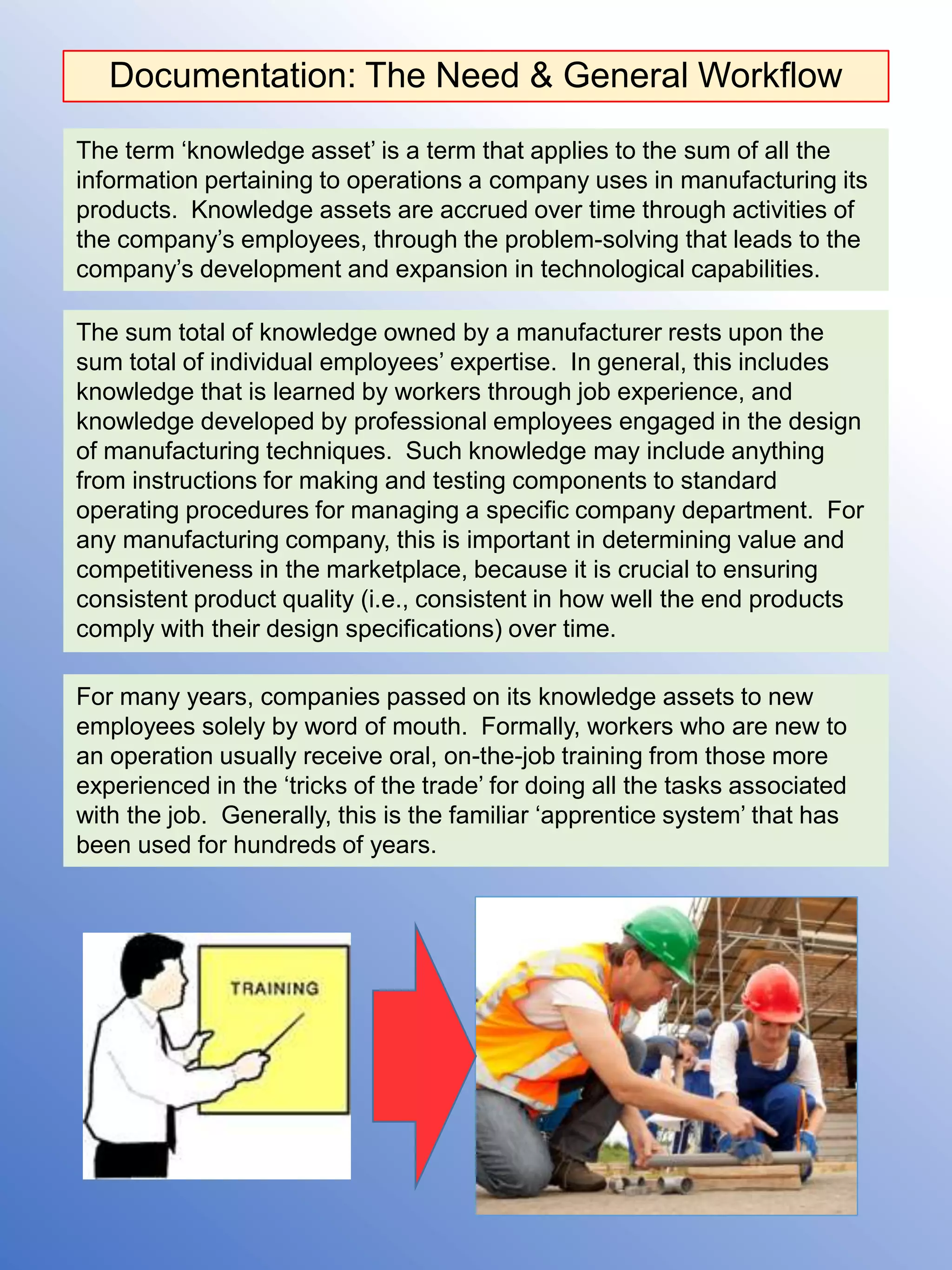
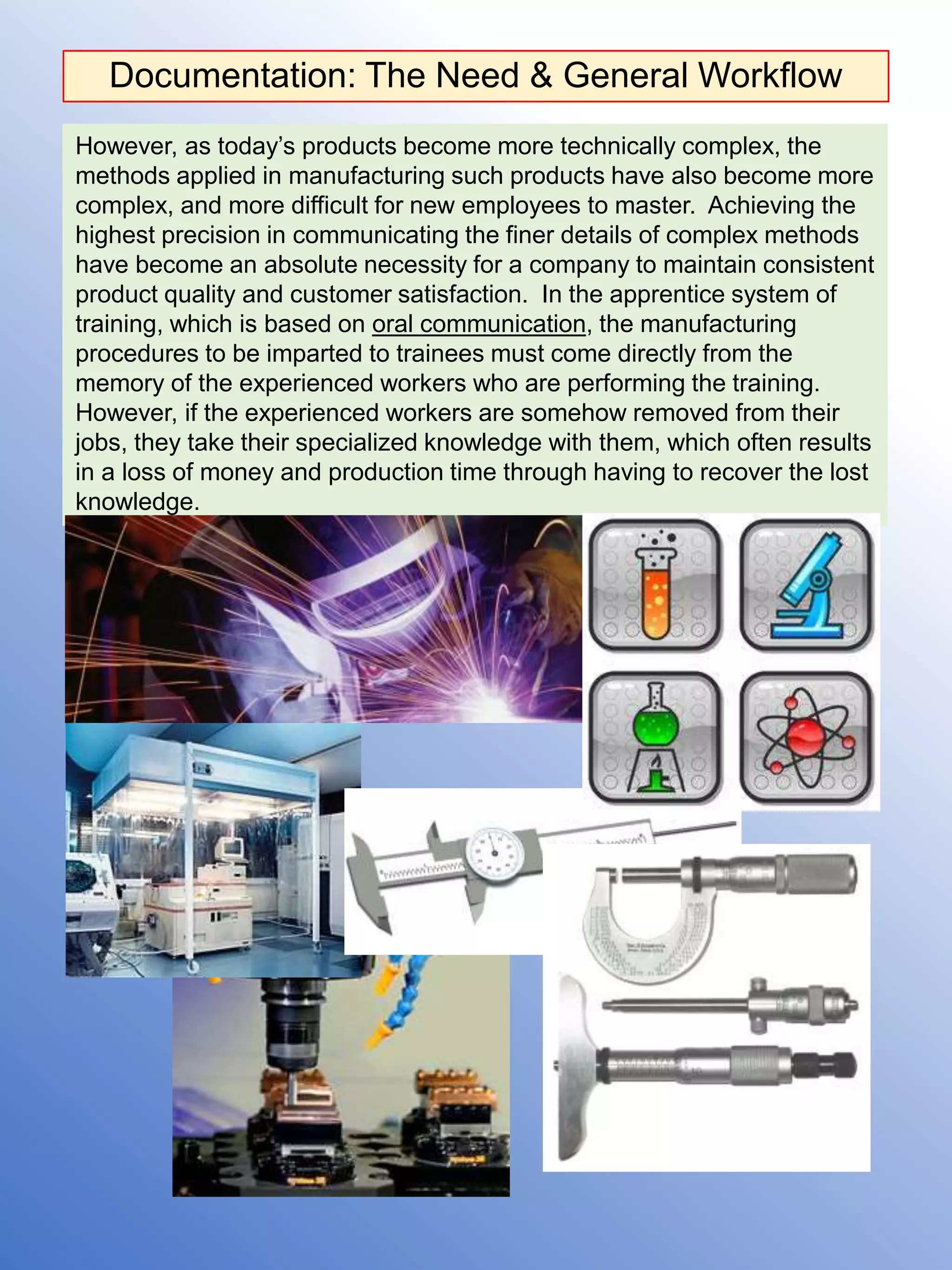
Technical
Documentation
For Quality Control & Work Standards
by Paul F. Geer
DOCUMENTATION: REASONS
FOR NEEDING IT & GENERAL
WORKFLOW FOR WRITING IT
Documentation: The Need & General Workflow
The sum total of knowledge owned by a manufacturer rests upon the
sum total of individual employees’ expertise. In general, this includes
knowledge that is learned by workers through job experience, and
knowledge developed by professional employees engaged in the design
of manufacturing techniques. Such knowledge may include anything
from instructions for making and testing components to standard
operating procedures for managing a specific company department. For
any manufacturing company, this is important in determining value and
competitiveness in the marketplace, because it is crucial to ensuring
consistent product quality (i.e., consistent in how well the end products
comply with their design specifications) over time.
For many years, companies passed on its knowledge assets to new
employees solely by word of mouth. Formally, workers who are new to
an operation usually receive oral, on-the-job training from those more
experienced in the ‘tricks of the trade’ for doing all the tasks associated
with the job. Generally, this is the familiar ‘apprentice system’ that has
been used for hundreds of years.
The term ‘knowledge asset’ is a term that applies to the sum of all the
information pertaining to operations a company uses in manufacturing its
products. Knowledge assets are accrued over time through activities of
the company’s employees, through the problem-solving that leads to the
company’s development and expansion in technological capabilities.
However, as today’s products become more technically complex, the
methods applied in manufacturing such products have also become more
complex, and more difficult for new employees to master. Achieving the
highest precision in communicating the finer details of complex methods
have become an absolute necessity for a company to maintain consistent
product quality and customer satisfaction. In the apprentice system of
training, which is based on oral communication, the manufacturing
procedures to be imparted to trainees must come directly from the
memory of the experienced workers who are performing the training.
However, if the experienced workers are somehow removed from their
jobs, they take their specialized knowledge with them, which often results
in a loss of money and production time through having to recover the lost
knowledge.
Documentation: The Need & General Workflow
Companies now face the reality of loosing profitability, because of the risk
of loosing knowledge assets vested in personnel with highly specialized
job skills. A company’s ability to maintain product quality on a consistent
basis may be seriously affected, if employees were to suddenly become
unavailable to train others through an organizational downsizing.
Thus, in today’s manufacturing environments, the apprentice system is
no longer a safe way for a company to invest its knowledge for training
new employees, if consistent product quality is to be assured. Employee
training will not be effective and company knowledge, safe from
loss, unless the training is supplemented with written materials that
identify and delineate the precise details for executing its jobs.
Most tech manufacturers, especially those specializing in electronics and
optics, are now seeking to show commitment to customer satisfaction by
observing a standard quality system that ensures products consistently
meet design requirements, to ensure continued profitability. These days,
it has become the norm for such companies to receive certifications by
agencies such as the International Standards Organization, or ISO. In
particular, to obtain an ISO 9001 certification, the company must demon-
strate it follows a quality management system that is compliant with the
current ISO requirements. According ISO 9001, the quality management
system must be effective in enabling the company to achieve customer
satisfaction, and regulatory compliance relevant to the products manu-
factured; and it must be adequately documented for training employees.
Documentation: The Need & General Workflow
To fulfill ISO 9001, manufacturers generally must preserve their current
knowledge assets (i.e., current procedures and policies) in the form of
electronic and/or hardcopy documents, for employees’ on-the-job or
computer based training (or for general referencing). Employees today
often have direct computer access to step-by-step work instructions,
procedures, part drawings, and other knowledge assets detailing
complex manufacturing information. In many instances, content libraries
are now available for quick access to training on specialized machining
steps, component testing procedures, etc., that can be used to
complement oral training by experienced employees.
Once carefully detailed documentation is maintained in a content library,
or repository, the risk of loosing information becomes much less, and the
information becomes much easier to control, provided that ISO
requirements are carefully followed.
ISO 9001 further requires companies to clearly define the processes and
policies used to control and store the documentation. This requirement
ensures that employees are referencing policies and procedures that are
current in the organization. It can apply to documents in many different
formats. Standardized data sheets are one example, because recording
requirements are subject to change. It often includes blueprints and
photographs, which play a crucial role in a company’s quality system.
Documentation: The Need & General Workflow
The steps taken to build a document repository involve identifying and
closing any gaps in available documentation. For example, one might
find a lack of training documentation on special drilling techniques in
which many man-hours have been involved in devising original concepts
and applications. Such an issue represents a gap – it concerns a highly
specialized process, so the knowledge of how to execute this process
represents a very important asset, and one that a company cannot afford
to lose through a loss of employees skilled in the process. Unless
documented, this asset can become like a missing puzzle piece that the
company might spend many man-hours trying to replace through
retracing procedure steps. The company’s response would then be to
assign a responsible person to analyze and document the process, to
eliminate the gap.
In developing a document for the quality management system, the author
assigned may research manuals and online information, make direct
observations of equipment and worker activities, and conduct interviews
of the relevant personnel. Beyond simple text, a typical document may
ultimately include: 1) illustrations, 2) photographs, 3) screen snapshots,
and 4) charts.
BUILDING A DOCUMENT REPOSITORY
Documentation: The Need & General Workflow
The graphic on the next page represents the general workflow used in
creating process documentation.
After preparation, the document is then tested in the field for content
accuracy and completeness, after which it is submitted to reviewers for
final approval. Once approved, the document is then stored in the
common repository for general access by employees (i.e., the document
becomes PUBLISHED).
Once they become available, the documents must reflect any
subsequent content changes in compliance with the ISO 9001 business
standard. Any standard operating procedure, work instruction, or other
process document must include a clearly visible record, preferably on the
cover page, showing the version, the edits made, and reviewer’s
certifying signatures so employees know they are reading the current
procedures and policies of the company. These should also include
identification numbers, department name, and other data that facilitates
tracking in an information database.
COVER PAGE
IDENTIFICATION
CHANGE RECORD
SIGN – OFF
Technical Writing Process Map
Manufacturing
Quality Control
Tech Writing
Requirement
INFORMATION GATHERING
Subject Matter Experts
Equipment Manuals
Technical Drawings
Material Data Sheets
Machine Operators
Engineers
Supervisors
Notes
Video recordings
Photographs
Screen snapshots
Identify process steps
Develop process description
Observations
Review technical
writing requirement &
determine scope
DEVELOP CONTENT –
TEXT & GRAPHICS
Document
Template
END
USER
TEST
Accept? PUBLISH
EDIT DOCUMENT PER
CUSTOMER REQUESTS
HARD COPY
E- COPY
Customer
Approval
Signature
YES
NO
GAP
ANALYSIS
List of Samples in this Presentation
• The following are writing samples taken from an
assortment of process documents written by
Paul F. Geer.
• The documents were written to provide training
and referencing for the production of optical
elements used in high-precision applications.
• The documents address five issues critical to
maintaining quality & customer satisfaction:
 Cleanliness of Glass Materials
 Uniform Performance of Materials
 Size of Defects and Impurities
 Surface Reflectivity
 Standard Workmanship
• The samples are a representation of the content
typically provided in documentation – charts,
drawings, tables, text formats, etc.
PROCEDURE FOR
CLEANING GLASS
MATERIALS
1.
Cleaning Fused Silica Glass
OVERVIEW
One important job in the quality control of precision ground glass is to
make sure the glass is free of defects and is clean enough to use in the
manufacturing process. To facilitate inspection for tiny scratches, pits,
bubbles, chips etc. in the glass, the technicians often must clean the
glass surfaces to remove residue. In addition, the cleaning of glass
surfaces is needed to remove any residue introduced through handling,
which may create issues for further processing.
The sample below is taken from a document describing the procedure for
cleaning fused silica glass, a material frequently used to make precision
optics. It describes the application of three chemical agents to clean
surfaces: alcohol, acetone, and a solution of powder soap called
ORVUS.
Cleaning Fused Silica Glass
Mouse drawings by
Paul Geer
Cleaning Fused Silica Glass
Mouse drawings by
Paul Geer
REFRACTIVE
INDEX
VERIFICATION OF
OPTICAL GLASS
2.
Refractive Index Verification of Optical Glass
OVERVIEW
Typically, in the production of high-precision optics, it is often critical that
raw glass materials be of the highest possible quality in performance.
The glass must be free of any non-uniformities in optical properties that
may compromise the performance, after optical components have been
cut and polished from it. One important inspection of incoming raw glass
materials is to verify the refractive index, a key indicator affecting light
bending properties that ultimately determine the light’s path through
finished optical elements.
The text below is from a document describing a process for measuring
deviation angle of light of known wavelength shown through a witness
sample, a sample of glass material (prism-shaped) associated with the
batch of molten glass from which the raw material was prepared. The
deviation angle observed in the light, which is influenced by refractive
index. The deviation angle is inspected against the limiting optical path
deviation specified for best performance. The material is ‘inspected’ by
inserting the witness sample into a spectrometer (above), wherein the
light source has a characteristic wavelength.
SPECTROMETER
Witness Sample
Light Source
Eyepiece & Angle
Measuring Reticle
Refractive Index Verification of Optical Glass
Mouse drawings by
Paul Geer
Refractive Index Verification of Optical Glass
Mouse drawings by
Paul Geer
Refractive Index Verification of Optical Glass
MEASURING SIZE
OF GLASS
DEFECTS AND
IMPURITIES
3.
Measuring Size of Glass Defects
OVERVIEW
Glass materials used to make optics often must meet a specified limit in
the size and number of embedded defects. The specified limit depends
on the application intended for the optical elements to be fabricated. In
high-technology applications, this limit is often very stringent because of
the precision required in the finished products. If the sizes and quantities
of defects are excessive enough, the light transmission through optical
elements will be negatively influenced, which could result in the optical
element not meeting performance requirements. However, if stringent
limits are imposed, there will be little difference in performance from that
of a hypothetical element with absolutely no defects. (All glass materials
will have some, however, regardless of the purification methods used.)
The text below is the introduction from a document describing the
procedure for using a simple projection system designed for inspecting
and measuring the size of glass defects. The projection system
magnifies the optical element, thus enlarging the defects and making the
defects easier to measure.
Measuring Size of Glass Defects
Mouse drawings by
Paul Geer
REFLECTIVITY
MEASUREMENTS
OF
BEAMSPLITTERS
4.
Reflectivity Measurements
OVERVIEW
Certain optical systems include high-precision beamsplitter cubes
assembled using two prism halves contacted together at the hypotenuse.
One very important quality requirement for a beamsplitter cube is its
ability to reflect light at the surface of contact. This is because, for certain
applications, a beamsplitter is needed to divide light into two parts, where
each part must meet certain minimal characteristics to ensure proper
functioning of the entire optical system in which the beamsplitter is to be
included.
The text below describes a test station for measuring relative light
intensity; i.e., the intensity of reflected light as compared with the
intensity of light incident on the beamsplitter.
Reflectivity Measurements
MANUFACTURING
WORK STANDARDS
5.
Manufacturing Work Standards
OVERVIEW – Manufacturing Procedures
Most manufacturing follows a sequence of steps designed so that the
end products meet all quality requirements of their design. To observe
the ISO 9001 business standard, a manufacturing company must have
all of its processes documented to preserve the knowledge necessary for
training workers.
The text below presents excerpts from standard operating procedures
prepared for optical manufacturing work centers. It focuses on four
pieces of equipment typically used in the optics industry:
 Aspheric Surface Generator (used for Precision Grinding)
 Centrifuge System (used for Removing Particulates from Coolant)
 Laser Etcher (used for Engraving Part Numbers & Serial Numbers)
 Calibration System for QTH Arc Lamps
Manufacturing Work Standards
• Aspheric Grinder
This section presents part of a maintenance work standard for a CNC
surface generator. It is text describing how the required maintenance
tasks are broken down according to specific parts, or zones, that are
included in the complete work center. The equipment introduction then
proceeds to the maintenance schedule for ZONE 1, for a part of the work
center called the centrifuge.
Manufacturing Work Standards
• Coolant Centrifuge
This section presents part of a detailed work standard for cleaning a
coolant centrifuge, an important component of most glass and metal work
centers. The particular centrifuge covered was used to filter out glass
particulates from liquid used to lubricate a grinding tool. The excerpt is
an explanation of key components prior to discussing the maintenance
steps.
Manufacturing Work Standards
• Laser Etcher
This section presents part of a work standard detailing how to operate a
laser etcher to engrave identification numbers onto components. The
excerpt includes an introduction that explains the hardware and software
used in the system. This introduction is then followed by the beginning of
the step procedure, which starts with a PRECAUTIONS Section that
includes a laser warning and an alert to the operator about a spacing
tool.
Manufacturing Work Standards
• Arc Lamp Calibration
The following text is an outline of a calibration procedure that is applied
to arc lamps used in light research. Calibration data is needed for QTH
lamps sold on the market, to match the brightness of standard arc lamps
over the visible light spectrum.
Manufacturing Work Standards
FINAL COMMENTS:
MS WORD TOOLS FOR
DOCUMENT DESIGN
Comments: MS Word Tools
Microsoft Word offers a number of tools that are useful in the design of
official documents. These cover a broad range of commands for creating
such elements as tables, numbered paragraphs, and drawings. The
tools allow the writer many options for customization when it comes to
formatting documents to suit the requirements of a company, or a
department within the company.
The following is a list of the important dialog boxes that were used to
design the documents in this presentation.
 Paragraph
 Font
 Page Setup
 Insert Table / Table Properties / Borders & Shading
 Table of Contents
 Table of Figures
 Styles
 Caption
 Insert Hyperlink
 Equation Editor
 Bullets & Numbering
 Headers & Footers
The Tables dialog boxes were used to create the revision record and
sign-off page, which is generally the cover page. The Headers & Footers
command was applied for displaying identification numbers and revision
levels on each page of the documents.

Technical Documentation of Quality Control and Work Standards

  • 1.
    Technical Documentation For Quality Control& Work Standards by Paul F. Geer
  • 2.
    DOCUMENTATION: REASONS FOR NEEDINGIT & GENERAL WORKFLOW FOR WRITING IT
  • 3.
    Documentation: The Need& General Workflow The sum total of knowledge owned by a manufacturer rests upon the sum total of individual employees’ expertise. In general, this includes knowledge that is learned by workers through job experience, and knowledge developed by professional employees engaged in the design of manufacturing techniques. Such knowledge may include anything from instructions for making and testing components to standard operating procedures for managing a specific company department. For any manufacturing company, this is important in determining value and competitiveness in the marketplace, because it is crucial to ensuring consistent product quality (i.e., consistent in how well the end products comply with their design specifications) over time. For many years, companies passed on its knowledge assets to new employees solely by word of mouth. Formally, workers who are new to an operation usually receive oral, on-the-job training from those more experienced in the ‘tricks of the trade’ for doing all the tasks associated with the job. Generally, this is the familiar ‘apprentice system’ that has been used for hundreds of years. The term ‘knowledge asset’ is a term that applies to the sum of all the information pertaining to operations a company uses in manufacturing its products. Knowledge assets are accrued over time through activities of the company’s employees, through the problem-solving that leads to the company’s development and expansion in technological capabilities.
  • 4.
    However, as today’sproducts become more technically complex, the methods applied in manufacturing such products have also become more complex, and more difficult for new employees to master. Achieving the highest precision in communicating the finer details of complex methods have become an absolute necessity for a company to maintain consistent product quality and customer satisfaction. In the apprentice system of training, which is based on oral communication, the manufacturing procedures to be imparted to trainees must come directly from the memory of the experienced workers who are performing the training. However, if the experienced workers are somehow removed from their jobs, they take their specialized knowledge with them, which often results in a loss of money and production time through having to recover the lost knowledge. Documentation: The Need & General Workflow
  • 5.
    Documentation: The Need& General Workflow Companies now face the reality of loosing profitability, because of the risk of loosing knowledge assets vested in personnel with highly specialized job skills. A company’s ability to maintain product quality on a consistent basis may be seriously affected, if employees were to suddenly become unavailable to train others through an organizational downsizing. Thus, in today’s manufacturing environments, the apprentice system is no longer a safe way for a company to invest its knowledge for training new employees, if consistent product quality is to be assured. Employee training will not be effective and company knowledge, safe from loss, unless the training is supplemented with written materials that identify and delineate the precise details for executing its jobs. Most tech manufacturers, especially those specializing in electronics and optics, are now seeking to show commitment to customer satisfaction by observing a standard quality system that ensures products consistently meet design requirements, to ensure continued profitability. These days, it has become the norm for such companies to receive certifications by agencies such as the International Standards Organization, or ISO. In particular, to obtain an ISO 9001 certification, the company must demon- strate it follows a quality management system that is compliant with the current ISO requirements. According ISO 9001, the quality management system must be effective in enabling the company to achieve customer satisfaction, and regulatory compliance relevant to the products manu- factured; and it must be adequately documented for training employees.
  • 6.
    Documentation: The Need& General Workflow To fulfill ISO 9001, manufacturers generally must preserve their current knowledge assets (i.e., current procedures and policies) in the form of electronic and/or hardcopy documents, for employees’ on-the-job or computer based training (or for general referencing). Employees today often have direct computer access to step-by-step work instructions, procedures, part drawings, and other knowledge assets detailing complex manufacturing information. In many instances, content libraries are now available for quick access to training on specialized machining steps, component testing procedures, etc., that can be used to complement oral training by experienced employees. Once carefully detailed documentation is maintained in a content library, or repository, the risk of loosing information becomes much less, and the information becomes much easier to control, provided that ISO requirements are carefully followed. ISO 9001 further requires companies to clearly define the processes and policies used to control and store the documentation. This requirement ensures that employees are referencing policies and procedures that are current in the organization. It can apply to documents in many different formats. Standardized data sheets are one example, because recording requirements are subject to change. It often includes blueprints and photographs, which play a crucial role in a company’s quality system.
  • 7.
    Documentation: The Need& General Workflow The steps taken to build a document repository involve identifying and closing any gaps in available documentation. For example, one might find a lack of training documentation on special drilling techniques in which many man-hours have been involved in devising original concepts and applications. Such an issue represents a gap – it concerns a highly specialized process, so the knowledge of how to execute this process represents a very important asset, and one that a company cannot afford to lose through a loss of employees skilled in the process. Unless documented, this asset can become like a missing puzzle piece that the company might spend many man-hours trying to replace through retracing procedure steps. The company’s response would then be to assign a responsible person to analyze and document the process, to eliminate the gap. In developing a document for the quality management system, the author assigned may research manuals and online information, make direct observations of equipment and worker activities, and conduct interviews of the relevant personnel. Beyond simple text, a typical document may ultimately include: 1) illustrations, 2) photographs, 3) screen snapshots, and 4) charts. BUILDING A DOCUMENT REPOSITORY
  • 8.
    Documentation: The Need& General Workflow The graphic on the next page represents the general workflow used in creating process documentation. After preparation, the document is then tested in the field for content accuracy and completeness, after which it is submitted to reviewers for final approval. Once approved, the document is then stored in the common repository for general access by employees (i.e., the document becomes PUBLISHED). Once they become available, the documents must reflect any subsequent content changes in compliance with the ISO 9001 business standard. Any standard operating procedure, work instruction, or other process document must include a clearly visible record, preferably on the cover page, showing the version, the edits made, and reviewer’s certifying signatures so employees know they are reading the current procedures and policies of the company. These should also include identification numbers, department name, and other data that facilitates tracking in an information database. COVER PAGE IDENTIFICATION CHANGE RECORD SIGN – OFF
  • 9.
    Technical Writing ProcessMap Manufacturing Quality Control Tech Writing Requirement INFORMATION GATHERING Subject Matter Experts Equipment Manuals Technical Drawings Material Data Sheets Machine Operators Engineers Supervisors Notes Video recordings Photographs Screen snapshots Identify process steps Develop process description Observations Review technical writing requirement & determine scope DEVELOP CONTENT – TEXT & GRAPHICS Document Template END USER TEST Accept? PUBLISH EDIT DOCUMENT PER CUSTOMER REQUESTS HARD COPY E- COPY Customer Approval Signature YES NO GAP ANALYSIS
  • 10.
    List of Samplesin this Presentation • The following are writing samples taken from an assortment of process documents written by Paul F. Geer. • The documents were written to provide training and referencing for the production of optical elements used in high-precision applications. • The documents address five issues critical to maintaining quality & customer satisfaction:  Cleanliness of Glass Materials  Uniform Performance of Materials  Size of Defects and Impurities  Surface Reflectivity  Standard Workmanship • The samples are a representation of the content typically provided in documentation – charts, drawings, tables, text formats, etc.
  • 11.
  • 12.
    Cleaning Fused SilicaGlass OVERVIEW One important job in the quality control of precision ground glass is to make sure the glass is free of defects and is clean enough to use in the manufacturing process. To facilitate inspection for tiny scratches, pits, bubbles, chips etc. in the glass, the technicians often must clean the glass surfaces to remove residue. In addition, the cleaning of glass surfaces is needed to remove any residue introduced through handling, which may create issues for further processing. The sample below is taken from a document describing the procedure for cleaning fused silica glass, a material frequently used to make precision optics. It describes the application of three chemical agents to clean surfaces: alcohol, acetone, and a solution of powder soap called ORVUS.
  • 13.
  • 14.
  • 15.
    Cleaning Fused SilicaGlass Mouse drawings by Paul Geer
  • 16.
    Cleaning Fused SilicaGlass Mouse drawings by Paul Geer
  • 17.
  • 18.
    Refractive Index Verificationof Optical Glass OVERVIEW Typically, in the production of high-precision optics, it is often critical that raw glass materials be of the highest possible quality in performance. The glass must be free of any non-uniformities in optical properties that may compromise the performance, after optical components have been cut and polished from it. One important inspection of incoming raw glass materials is to verify the refractive index, a key indicator affecting light bending properties that ultimately determine the light’s path through finished optical elements. The text below is from a document describing a process for measuring deviation angle of light of known wavelength shown through a witness sample, a sample of glass material (prism-shaped) associated with the batch of molten glass from which the raw material was prepared. The deviation angle observed in the light, which is influenced by refractive index. The deviation angle is inspected against the limiting optical path deviation specified for best performance. The material is ‘inspected’ by inserting the witness sample into a spectrometer (above), wherein the light source has a characteristic wavelength. SPECTROMETER Witness Sample Light Source Eyepiece & Angle Measuring Reticle
  • 19.
    Refractive Index Verificationof Optical Glass Mouse drawings by Paul Geer
  • 20.
    Refractive Index Verificationof Optical Glass Mouse drawings by Paul Geer
  • 21.
  • 22.
  • 23.
  • 24.
  • 25.
  • 26.
    Measuring Size ofGlass Defects OVERVIEW Glass materials used to make optics often must meet a specified limit in the size and number of embedded defects. The specified limit depends on the application intended for the optical elements to be fabricated. In high-technology applications, this limit is often very stringent because of the precision required in the finished products. If the sizes and quantities of defects are excessive enough, the light transmission through optical elements will be negatively influenced, which could result in the optical element not meeting performance requirements. However, if stringent limits are imposed, there will be little difference in performance from that of a hypothetical element with absolutely no defects. (All glass materials will have some, however, regardless of the purification methods used.) The text below is the introduction from a document describing the procedure for using a simple projection system designed for inspecting and measuring the size of glass defects. The projection system magnifies the optical element, thus enlarging the defects and making the defects easier to measure.
  • 27.
    Measuring Size ofGlass Defects
  • 28.
    Measuring Size ofGlass Defects
  • 29.
    Measuring Size ofGlass Defects Mouse drawings by Paul Geer
  • 30.
  • 31.
    Reflectivity Measurements OVERVIEW Certain opticalsystems include high-precision beamsplitter cubes assembled using two prism halves contacted together at the hypotenuse. One very important quality requirement for a beamsplitter cube is its ability to reflect light at the surface of contact. This is because, for certain applications, a beamsplitter is needed to divide light into two parts, where each part must meet certain minimal characteristics to ensure proper functioning of the entire optical system in which the beamsplitter is to be included. The text below describes a test station for measuring relative light intensity; i.e., the intensity of reflected light as compared with the intensity of light incident on the beamsplitter.
  • 32.
  • 33.
  • 34.
  • 35.
    Manufacturing Work Standards OVERVIEW– Manufacturing Procedures Most manufacturing follows a sequence of steps designed so that the end products meet all quality requirements of their design. To observe the ISO 9001 business standard, a manufacturing company must have all of its processes documented to preserve the knowledge necessary for training workers. The text below presents excerpts from standard operating procedures prepared for optical manufacturing work centers. It focuses on four pieces of equipment typically used in the optics industry:  Aspheric Surface Generator (used for Precision Grinding)  Centrifuge System (used for Removing Particulates from Coolant)  Laser Etcher (used for Engraving Part Numbers & Serial Numbers)  Calibration System for QTH Arc Lamps
  • 36.
    Manufacturing Work Standards •Aspheric Grinder This section presents part of a maintenance work standard for a CNC surface generator. It is text describing how the required maintenance tasks are broken down according to specific parts, or zones, that are included in the complete work center. The equipment introduction then proceeds to the maintenance schedule for ZONE 1, for a part of the work center called the centrifuge.
  • 37.
  • 38.
  • 39.
  • 40.
  • 41.
  • 42.
    Manufacturing Work Standards •Coolant Centrifuge This section presents part of a detailed work standard for cleaning a coolant centrifuge, an important component of most glass and metal work centers. The particular centrifuge covered was used to filter out glass particulates from liquid used to lubricate a grinding tool. The excerpt is an explanation of key components prior to discussing the maintenance steps.
  • 43.
  • 44.
  • 45.
    Manufacturing Work Standards •Laser Etcher This section presents part of a work standard detailing how to operate a laser etcher to engrave identification numbers onto components. The excerpt includes an introduction that explains the hardware and software used in the system. This introduction is then followed by the beginning of the step procedure, which starts with a PRECAUTIONS Section that includes a laser warning and an alert to the operator about a spacing tool.
  • 46.
  • 47.
  • 48.
  • 49.
  • 50.
    Manufacturing Work Standards •Arc Lamp Calibration The following text is an outline of a calibration procedure that is applied to arc lamps used in light research. Calibration data is needed for QTH lamps sold on the market, to match the brightness of standard arc lamps over the visible light spectrum.
  • 51.
  • 52.
  • 53.
    FINAL COMMENTS: MS WORDTOOLS FOR DOCUMENT DESIGN
  • 54.
    Comments: MS WordTools Microsoft Word offers a number of tools that are useful in the design of official documents. These cover a broad range of commands for creating such elements as tables, numbered paragraphs, and drawings. The tools allow the writer many options for customization when it comes to formatting documents to suit the requirements of a company, or a department within the company. The following is a list of the important dialog boxes that were used to design the documents in this presentation.  Paragraph  Font  Page Setup  Insert Table / Table Properties / Borders & Shading  Table of Contents  Table of Figures  Styles  Caption  Insert Hyperlink  Equation Editor  Bullets & Numbering  Headers & Footers The Tables dialog boxes were used to create the revision record and sign-off page, which is generally the cover page. The Headers & Footers command was applied for displaying identification numbers and revision levels on each page of the documents.