Download to read offline
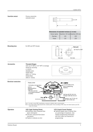
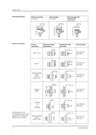
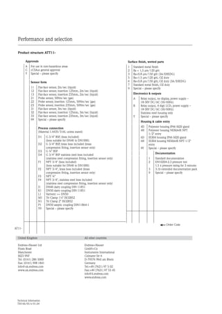

The document provides technical information about the T-Switch AT11 thermal flow switch suitable for liquids and gases, highlighting its applications across various industries such as process plants, chemical, water treatment, beverage, and dairy industries. It details the sensor's specifications, installation guidelines, performance metrics, materials used, and compliance with various industry standards and approvals. Key features include dry run protection, no moving parts for reduced maintenance, and a variety of process connections with maximum specifications for temperature and pressure.


