Downloaded 234 times
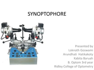

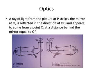
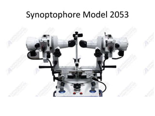


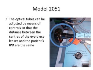
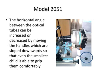

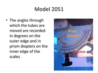
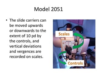


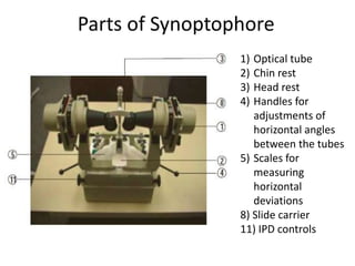
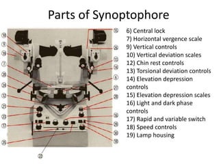
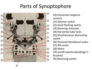


The synoptophore is an instrument used in orthoptics to test binocular vision. It presents different images to each eye to test fusional abilities. The synoptophore was developed in the early 20th century based on the haploscopic principle. It uses mirrors and lenses to direct different images to each eye. Various models have different additional features like afterimage devices, automatic flashing, and measurement of vertical/torsional deviations. A wide range of slides can test functions like stereopsis, fusion, suppression, and retinal correspondence. The synoptophore is useful for both diagnosing binocular vision disorders and providing vergence therapy.


