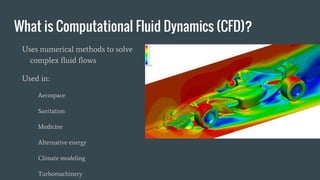
Ansys 15.0 CFD Processing
SURP 2015
Matt Goodman | Victor Heinen | Josh Solberg
Advisor: Dr. Emin Issakhanian
What is Computational Fluid Dynamics (CFD)?
Uses numerical methods to solve
complex fluid flows
Used in:
Aerospace
Sanitation
Medicine
Alternative energy
Climate modeling
Turbomachinery
Film-cooling effectiveness
Film cooling: uses cool air flowing
through a hole to form a barrier
between the material and hot fluid
Dr. Issakhanian’s dissertation compared
the film cooling effectiveness of
different shaped holes
We tried to duplicate these results using
ANSYS Fluent 15.0
CFD Process
There are many methods, which can be chosen
based on the desired results
We used Ansys 15.0
● CAD Modeling
● Meshing
● Setup
● Solution
● Results
Geometry
The 3D (CAD) model of the fluid flow was created in SolidWorks
Main Flow Channel
Plenum
(Source of cool water)
Hole for cool water to
combine with main flow
Meshing
A CAD model is sliced into many individual (finite) elements that can be analyzed
using Finite Element Methods (FEM).
Meshes can be coarse (large elements) or fine (small elements) depending on the
required accuracy and the power of the computer.
Meshing
Setup - Input variables to define the flow being modeled
I.e. Is the flow Hot or Cold? Moving or Still? Water or Oil?
Momentum of fluid
Turbulence
Pressure
Mass flow rate
Boundary conditions
Temperature throughout fluid
Details of interaction between wall and fluid
Momentum and Boundary Conditions
Input
Temperature
Input
Setup - Input variables to define the flow being modeled
Flow Material
Water
Air
Refrigerant
Solution methods - (1st order vs 2nd order
equations etc.)
Determines amount of computational power put into
solution of mesh
Higher order solution methods increase the accuracy
Initialization
Solution
The program runs
numbers until all
residuals fall
below a chosen
value
Results
3 parameters were measured to try to match the results from Dr. Issakhanian’s
dissertation, and a 4th one was found
1. Velocity contours at the exit hole
2. Velocity contours at the midplane of the main flow
3. Vorticity comparison at a YZ-plane located at X/D = 2 (approximately 2cm) away
from the exit hole
4. Temperature contours on the bottom plane of the main flow channel
1.Exit Hole Velocity
Experimental Computational
2. Main Flow Velocity Contours
Experimental
Computational
3. X/D = 2 Vorticity Comparison
● Vorticity comparison in the YZ Plane at X/D=2
(approx 2cm) away from the exit hole
ComputationalExperimental
4. Surface Temperature
Thank You For Your Time
Questions?

Symposium PPT

  • 1.
    Ansys 15.0 CFDProcessing SURP 2015 Matt Goodman | Victor Heinen | Josh Solberg Advisor: Dr. Emin Issakhanian
  • 2.
    What is ComputationalFluid Dynamics (CFD)? Uses numerical methods to solve complex fluid flows Used in: Aerospace Sanitation Medicine Alternative energy Climate modeling Turbomachinery
  • 3.
    Film-cooling effectiveness Film cooling:uses cool air flowing through a hole to form a barrier between the material and hot fluid Dr. Issakhanian’s dissertation compared the film cooling effectiveness of different shaped holes We tried to duplicate these results using ANSYS Fluent 15.0
  • 4.
    CFD Process There aremany methods, which can be chosen based on the desired results We used Ansys 15.0 ● CAD Modeling ● Meshing ● Setup ● Solution ● Results
  • 5.
    Geometry The 3D (CAD)model of the fluid flow was created in SolidWorks Main Flow Channel Plenum (Source of cool water) Hole for cool water to combine with main flow
  • 6.
    Meshing A CAD modelis sliced into many individual (finite) elements that can be analyzed using Finite Element Methods (FEM). Meshes can be coarse (large elements) or fine (small elements) depending on the required accuracy and the power of the computer.
  • 7.
  • 8.
    Setup - Inputvariables to define the flow being modeled I.e. Is the flow Hot or Cold? Moving or Still? Water or Oil? Momentum of fluid Turbulence Pressure Mass flow rate Boundary conditions Temperature throughout fluid Details of interaction between wall and fluid
  • 9.
    Momentum and BoundaryConditions Input Temperature Input
  • 10.
    Setup - Inputvariables to define the flow being modeled Flow Material Water Air Refrigerant Solution methods - (1st order vs 2nd order equations etc.) Determines amount of computational power put into solution of mesh Higher order solution methods increase the accuracy Initialization
  • 11.
    Solution The program runs numbersuntil all residuals fall below a chosen value
  • 12.
    Results 3 parameters weremeasured to try to match the results from Dr. Issakhanian’s dissertation, and a 4th one was found 1. Velocity contours at the exit hole 2. Velocity contours at the midplane of the main flow 3. Vorticity comparison at a YZ-plane located at X/D = 2 (approximately 2cm) away from the exit hole 4. Temperature contours on the bottom plane of the main flow channel
  • 13.
  • 14.
    2. Main FlowVelocity Contours Experimental Computational
  • 15.
    3. X/D =2 Vorticity Comparison ● Vorticity comparison in the YZ Plane at X/D=2 (approx 2cm) away from the exit hole ComputationalExperimental
  • 16.
  • 17.
    Thank You ForYour Time Questions?

Editor's Notes

  • #6 Ansys 15.0 was utilized to try to duplicate the results from Dr. Emin Issakhanian’s Ph.D dissertation on film-cooling effectiveness. Film-cooling is a process in which cold fluid enters a hot flow through a hole in the material in order to create a cold “film” that protects the material from the thermal stresses to which it would be exposed otherwise. Dr. Issakhanian’s experiment involved comparing the characteristics of film-cooling through a round hole and an oval-shaped hole. CFD was used to model the characteristics of the oval-shaped hole results. Different characteristics of the velocities were measured and compared to the experimental results.