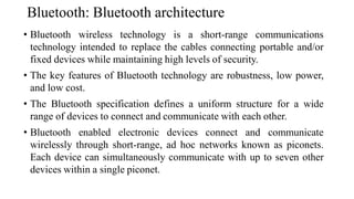
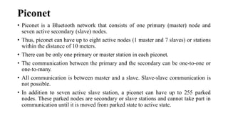
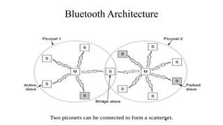
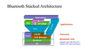
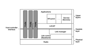
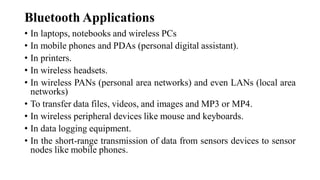
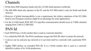
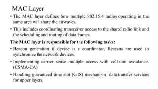
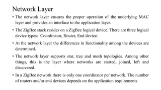
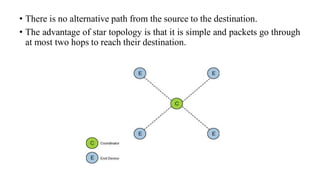
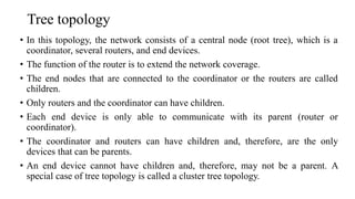
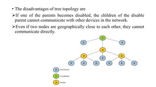
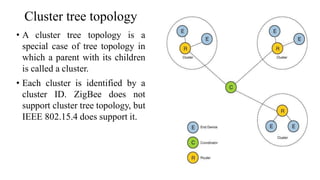
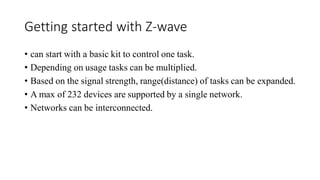
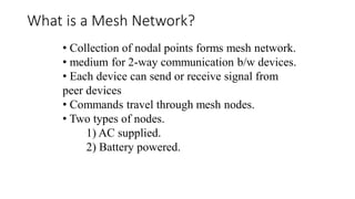
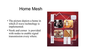
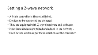
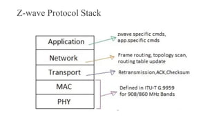
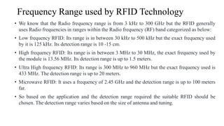
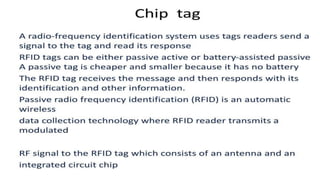
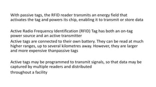
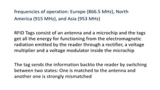
SlideShare a Scribd company logo
1 of 113
Download to read offline
Unit 2 :
Short Range Wireless Technologies
and Location Tracking
Prepared By:
Shubhangi Gaikar
Introduction
Bluetooth: Bluetooth architecture
• Bluetooth wireless technology is a short-range communications
technology intended to replace the cables connecting portable and/or
fixed devices while maintaining high levels of security.
• The key features of Bluetooth technology are robustness, low power,
and low cost.
• The Bluetooth specification defines a uniform structure for a wide
range of devices to connect and communicate with each other.
• Bluetooth enabled electronic devices connect and communicate
wirelessly through short-range, ad hoc networks known as piconets.
Each device can simultaneously communicate with up to seven other
devices within a single piconet.
Piconet
• Piconet is a Bluetooth network that consists of one primary (master) node and
seven active secondary (slave) nodes.
• Thus, piconet can have up to eight active nodes (1 master and 7 slaves) or stations
within the distance of 10 meters.
• There can be only one primary or master station in each piconet.
• The communication between the primary and the secondary can be one-to-one or
one-to-many.
• All communication is between master and a slave. Slave-slave communication is
not possible.
• In addition to seven active slave station, a piconet can have up to 255 parked
nodes. These parked nodes are secondary or slave stations and cannot take part in
communication until it is moved from parked state to active state.
Bluetooth Architecture
Scatternet
• Scatternet is formed by combining various piconets.
• A slave in one piconet can act as a master or primary in other
piconet.
• Such a station or node can receive messages from the master
in the first piconet and deliver the message to its slaves in
other piconet where it is acting as master. This node is also
called bridge slave.
• Thus a station can be a member of two piconets.
• A station cannot be a master in two piconets.
Bluetooth Stacked Architecture
RF
Baseband
Audio
Link Manager
L2CAP
Data
SDP RFCOMM
IP
Applications
(Single chip with RS-232,
USB or PC card interface)
Bluetooth chip
Firmware
Applications
• Radio: The Radio layer defines the requirements for a Bluetooth transceiver operating in the 2.4
GHz ISM band.
• Baseband: The Baseband layer describes the specification of the Bluetooth Link Controller (LC),
which carries out the baseband protocols and other low-level link. It specifies Piconet/Channel
definition, “Low-level” packet definition, Channel sharing
• LMP: The Link Manager Protocol (LMP) is used by the Link Managers (on either side) for link
set-up and control.
• HCI: The Host Controller Interface (HCI) provides a command interface to the Baseband Link
Controller and Link Manager, and access to hardware status and control registers. •
• L2CAP: Logical Link Control and Adaptation Protocol (L2CAP) supports higher level protocol
multiplexing, packet segmentation and reassembly, and the conveying of quality of service
information.
• RFCOMM: The RFCOMM protocol provides emulation of serial ports over the L2CAP protocol.
The protocol is based on the ETSI standard TS 07.10.
• SDP: The Service Discovery Protocol (SDP) provides a means for applications to discover, which
services are provided by or available through a Bluetooth device. It also allows applications to
determine the characteristics of those available services.
Bluetooth Layers :Layer 1: Radio Layer
• This is the lowest layer in the Bluetooth protocol stack. Bluetooth uses a technique called frequency
hopping, in establishing radio links with other Bluetooth devices. This layer of Bluetooth corresponds to
the physical layer of OSI model.
• It deals with ratio transmission and modulation. FHSS is used to coexist with other network.
• The radio layer moves data from master to slave or vice versa.
• It is a low power system that uses 2.4 GHz ISM band in a range of 10 meters.
• This partly gives the necessary protection to the transmitted data and avoids tampering. Standard hop
values are 79 hops, which are spaced at an interval of 1MHz. In some countries like France, due to
government regulations 23 hops are used.
• Transmitter characteristics: Each device is classified into 3 power classes, Power Class 1, 2 & 3.
• Power Class 1: is designed for long range (~100m) devices, with a max output power of 20 dBm
• Power Class 2: for ordinary range devices (~10m) devices, with a max output power of 4 dBm,
• Power Class 3: for short range devices (~10cm) devices, with a max output power of 0 dBm.
Layer 2: Baseband Layer
• The baseband is the digital engine of a Bluetooth system and equivalent to the MAC
sublayer in LANs.
• Bluetooth uses a form of TDMA called TDD-TDMA (time division duplex TDMA).
• Master and slave stations communicate with each other using time slots.
• In TDD- TDMA, communication is half duplex in which receiver can send and receive data
but not at the same time.
• It is responsible for constructing and decoding packets, encoding and managing error
correction, encrypting and decrypting for secure communications, calculating radio
transmission frequency patterns, maintaining synchronization, controlling the radio, and all
of the other low level details necessary to realize Bluetooth communications.
• The channel is represented by a pseudo-random hopping sequence hopping through the 79
or 23 RF channels. Two or more Bluetooth devices using the same channel form a piconet.
Layer 3: Link Manager Protocol
• The Link Manager is responsible for managing the physical details for Bluetooth connections.
• It is responsible for creating the links, monitoring their health, and terminating them
gracefully upon command or failure.
• The link manager is implemented in a mix of hardware and software.
• The Link Manager carries out link setup, authentication, link configuration and other
protocols.
• It discovers other remote LM’s and communicates with them via the Link Manager Protocol
(LMP).
• To perform its service provider role, the LM uses the services of the underlying Link
Controller (LC).
• The Link Manager Protocol essentially consists of a number of PDU (protocol Data Units),
which are sent from one device to another, determined by the AM_ADDR in the packet
header.
Layer 4: Host Controller Interface
• This is the layer of the stack that contains the firmware i.e. the
software that actually controls all the activities happening in the
Baseband and Radio layers.
• It provides a common interface between the Bluetooth host and a
Bluetooth module. It manages the hardware links with the scatternets.
• It also contains the drivers for the hardware devices used in the
connection. Basically the BIOS is loaded in the HCI Layer.
Layer 5: Logical Link Control and Adaptation Protocol
• The Logical Link Control and Adaptation Layer Protocol (L2CAP) is layered over the Baseband
Protocol and resides in the data link layer.
• It manages the high level aspects of each connection (who is connected to who, whether to use
encryption or not, what level of performance is required, etc.)
• In addition it is responsible for converting the format of data as necessary between the APIs and the
lower level Bluetooth protocols.
• L2CAP provides connection oriented and connectionless data services to upper layer protocols with
protocol multiplexing capability, segmentation and reassembly operation, and group abstractions.
• Two link types are supported for the Baseband layer:
• Synchronous Connection-Oriented (SCO) links and Asynchronous Connection-Less (ACL) links.
• L2CAP receives the packets of up to 64 KB from upper layers and divides them into frames for
transmission.
• L2CAP performs multiplexing at sender side and de-multiplexing at receiver side.
Layer 6: Radio Frequency Communication (RFCOMM)
• This is the most important layer in the Bluetooth architecture.
• RFCOMM takes care of the communication channel between two devices or between
a master and a slave.
• It connects the serial ports of all the devices according to the requirement.
• RFCOMM basically has to accommodate two kinds of devices:
1. Communication end-points such as computers or printers.
2. Devices that are a part of communication channel such as Modems.
• RFCOMM protocol is not aware of the distinction between these two kinds of
devices.
• To prevent any loss of data, it passes on all the information to both the devices. The
devices in turn distinguish between the data and filter it out
Layer 7: Service Discovery Protocol
• The service discovery protocol (SDP) provides a means for applications to discover
which services are available and to determine the characteristics of those available
services.
• A specific Service Discovery protocol is needed in the Bluetooth environment, as the
set of services that are available changes dynamically based on the RF proximity of
devices in motion.
• The service discovery protocol defined in the Bluetooth specification is intended to
address the unique characteristics of the Bluetooth environment.
• Bluetooth is basically a universal protocol. Manufacturers may embed Bluetooth
ports in their devices.
• SDP is very important when devices from different companies and from different
parts of the world are brought together. The devices try to recognize each other
through SDP.
Telephony Control Protocol Spec (TCS)
• Basic function of this layer is call control (setup & release) and group
management for gateway serving multiple devices.
Application Program Interface (API) libraries
• These are software modules which connect the host application program to
the Bluetooth communications system. As such they reside and execute on
the same processing resource as the host system application.
• Access Code: It is 72 bit field that contains
synchronization bits. It identifies the master.
• Header: This is 54-bit field. It contain 18 bit pattern
that is repeated for 3 time.
• The header field contains following sub-fields:
(i) Address: This 3 bit field can define up to seven
slaves (1 to 7). If the address is zero, it is used for
broadcast communication from primary to all
secondaries.
(ii)Type: This 4 bit field identifies the type of data
coming from upper layers.
(iii) F: This flow bit is used for flow control. When set
to 1, it means the device is unable to receive more
frames.
(iv) A: This bit is used for acknowledgement.
(v) S: This bit contains a sequence number of the frame
to detect re-transmission.
(vi) Checksum: This 8 bit field contains checksum to
detect errors in header.
• Data: This field can be 0 to 2744 bits long. It
contains data or control information coming from
upper layers
• Bluetooth Frame Format with Enhanced Data Rate
• The frame for enhanced data rate contains additionally a guard field
and a trailer as shown in the following diagram−
• The additional fields and changes in data field are−
• Guard− A 16-bit field containing a synchronization pattern that
enables to switch to higher data speed while transmitting the data field.
• Trailer− A 2-bit field denoting end of the variable length data field.
• Data− A variable length field ranging from 0 to 2744 bits that contains
high volume payload from upper layers.
Bluetooth Applications
• In laptops, notebooks and wireless PCs
• In mobile phones and PDAs (personal digital assistant).
• In printers.
• In wireless headsets.
• In wireless PANs (personal area networks) and even LANs (local area
networks)
• To transfer data files, videos, and images and MP3 or MP4.
• In wireless peripheral devices like mouse and keyboards.
• In data logging equipment.
• In the short-range transmission of data from sensors devices to sensor
nodes like mobile phones.
Zigbee
• Named from the “waggle” dance that honey bees do to communicate with each other.
• Erratic, zig-zagging patterns of bees between flowers.
• Symbolizes communication between nodes in a mesh network.
• Network components analogous to queen bee, drones, worker bees.
• ZigBee is a Ad-hoc networking technology for LRWPAN.
• Technological Standard Created for Control and Sensor Networks.
• Based On IEEE 802.15.4 standard that defines the PHY and Mac Layers for ZigBee.
• Low in cost ,complexity & power consumption as compared to competing
technologies.
• Data rates touch 250Kbps for 2.45Ghz ,40 Kbps 915Mhz and 20Kbps for 868Mhz
band.
What does ZigBee do?
• ZigBee is the most popular industry wireless mesh networking standard
for connecting sensors, instrumentation and control systems.
• It is used for embedded application for low data rates and Low power
consumption.
• Designed for wireless controls and sensors.
• Operates in Personal Area Networks (PAN’s) and device-to-device
networks.
• Connectivity between small packet devices.
• Control of lights, switches, thermostats, appliances, etc.
• ZigBee, a specification for communication in a wireless personal area
network (WPAN), which is very helpful in the "Internet of things."
Zigbee general characteristics
• Data rates of 20 kbps and up to 250 kbps.
• Low Power Usage consumption.
• 3 Frequencies bands with 27 channels.
• Extremely low duty-cycle.
• Supports large number of nodes.
• Low power consumption, Very long battery life. Users expect batteries to last many
months to years
• ZigBee transmission range is approx. 1-100 meters.
• Even mains powered equipment needs to be conscious of energy. ZigBee devices will
be more ecological than its predecessors saving megawatts at it full deployment.
• ZigBee is an open, global, packet-based protocol designed to provide an
easy-to-use architecture.
• Zigbee is designed for secure, reliable, low power wireless networks.
• ZigBee and IEEE 802.15.4 are low data rate wireless networking
standards that can eliminate the costly and damage prone wiring in
industrial control applications.
• Low cost (device, installation, maintenance)
• ZigBee’s use of the IEEE 802.15.4 PHY and MAC allows networks to
handle any number of devices.
• The ZigBee specification supports star and two kinds of peer-to-peer
topologies, mesh and cluster tree.
How Zigbee Works?
• ZigBee basically uses digital radios for communication with one another.
• It consists of several types of devices, where a network coordinator is a
device that sets up the network, and is aware of all the nodes within its
network.
• Network coordinator manages both the information from each node as
well as the information that is being transmitted/received within the
network.
• Every ZigBee network must contain a network coordinator. Other Full
Function Devices (FFD's) may be found in the network, and these devices
support all of the 802.15.4 functions.
• They can serve as network coordinators, network routers, or as devices
that interact with the physical world.
Zigbee stack
PHY Layer
• The basic task of the PHY layer is data transmission and reception.
• This involves modulation and spreading techniques that map bits of
information in such a way as to allow them to travel through the air.
• The PHY layer is also responsible for the following tasks:
• enable/disable the radio transceiver
• link quality indication (LQI) for received packets
• energy detection (ED) within the current channel
• clear channel assessment (CCA)
Transmitter and Receiver
• The power output of the transmitter and the sensitivity of the receiver
are determining factors of the signal strength and its range.
• Other determining factors include obstacles in the communication path
that cause interference with the signal.
• The higher the transmitter's output power, the longer the range of its
signal.
• On the other side, the receiver's sensitivity determines the minimum
power needed for the radio to reliably receive the signal.
• These values are described using dB.
Channels
• Of the three ISM frequency bands only the 2.4 GHz band operates worldwide.
• The 868 MHz band only operates in the EU and the 915 MHz band is only for North and South
America.
• However, if global interoperability is not a requirement, the relative emptiness of the 915 MHz
band in non European countries might be an advantage for some applications.
• For the 2.4 GHz band, IEEE 802.15.4 specifies communication should occur in 5 MHz channels
ranging from 2.405 to 2.480 GHz.
PAN Id
• Each WPAN has a 16-bit number that is used as a network identifier.
• It is called the PAN ID. The PAN coordinator assigns the PAN ID when it creates the network.
• A device can try and join any network or it can limit itself to a network with a particular PAN
ID.
• ZigBee PRO defines an extended PAN ID. It is a 64-bit number that is used as a network
identifier in place of its 16-bit predecessor.
MAC Layer
• The MAC layer defines how multiple 802.15.4 radios operating in the
same area will share the airwaves.
• This includes coordinating transceiver access to the shared radio link and
the scheduling and routing of data frames.
The MAC layer is responsible for the following tasks:
• Beacon generation if device is a coordinator, Beacons are used to
synchronize the network devices.
• Implementing carrier sense multiple access with collision avoidance.
(CSMA-CA)
• Handling guaranteed time slot (GTS) mechanism data transfer services
for upper layers.
Network Layer
• The network layer ensures the proper operation of the underlying MAC
layer and provides an interface to the application layer.
• The ZigBee stack resides on a ZigBee logical device. There are three logical
device types: Coordinator, Router, End device.
• At the network layer the differences in functionality among the devices are
determined.
• The network layer supports star, tree and mesh topologies. Among other
things, this is the layer where networks are started, joined, left and
discovered.
• In a ZigBee network there is only one coordinator per network. The number
of routers and/or end devices depends on the application requirements
• When a coordinator attempts to establish a ZigBee network, it does an
energy scan to find the best RF channel for its new network.
• When a channel has been chosen, the coordinator assigns the logical
network identifier, also known as the PAN ID, which will be applied to all
devices that join the network.
• The network layer provides security for the network, ensuring both
authenticity and confidentiality of a transmission.
Application framework
• The application framework is an execution environment for application objects to send
and receive data.
• Application objects are defined by the manufacturer of the ZigBee-enabled device.
• As defined by ZigBee, an application object is at the top of the application layer and is
determined by the device manufacturer.
• An application object actually implements the application; it can be a light bulb, a light
switch, an LED, an I/O line, etc.
• The application profile is run by the application objects. Each application object is
addressed through its corresponding endpoint.
• Endpoint numbers range from 1 to 240. Endpoint 0 is the address of the ZigBee Device
Object (ZDO). Endpoint 255 is the broadcast address, i.e., messages are sent to all of the
endpoints on a particular node.
• Endpoints 241 through 254 are reserved for future use.
Application Profiles
• Basically a profile is a message-handling agreement between applications on
different devices.
• A profile describes the logical components and their interfaces. Typically, no code
is associated with a profile.
• The main reason for using a profile is to provide interoperability between different
manufacturers.
• For example, with the use of the Home Lighting profile, a consumer could use a
wireless switch from one manufacturer to control the lighting fixture from another
manufacturer.
• There are three types of profiles: public (standard), private and published. Public
profiles are managed by the ZigBee Alliance.
• Private profiles are defined by ZigBee vendors for restricted use. A private profile
can become a published profile if the owner of the profile decides to publish it.
ZigBee Bluetooth
ZigBee Topologies
• IEEE 802.15.4 offers star, tree, cluster tree, and mesh topologies; however,
ZigBee supports only star, tree, and mesh topologies.
• It uses an association hierarchy; a device joining the network can either be a
router or an end device, and routers can accept more devices.
• Star topology: The star topology consists of a coordinator and several end
devices (nodes)
• In this topology, the end device communicates only with the coordinator. Any
packet exchange between end devices must go through the coordinator.
• The disadvantage of this topology is the operation of the network depends on
the coordinator of the network, and because all packets between devices must
go through coordinator, the coordinator may become bottlenecked.
• There is no alternative path from the source to the destination.
• The advantage of star topology is that it is simple and packets go through
at most two hops to reach their destination.
Tree topology
• In this topology, the network consists of a central node (root tree), which is a
coordinator, several routers, and end devices.
• The function of the router is to extend the network coverage.
• The end nodes that are connected to the coordinator or the routers are called
children.
• Only routers and the coordinator can have children.
• Each end device is only able to communicate with its parent (router or
coordinator).
• The coordinator and routers can have children and, therefore, are the only
devices that can be parents.
• An end device cannot have children and, therefore, may not be a parent. A
special case of tree topology is called a cluster tree topology.
• The disadvantages of tree topology are
➢If one of the parents becomes disabled, the children of the disable
parent cannot communicate with other devices in the network.
➢Even if two nodes are geographically close to each other, they cannot
communicate directly.
Cluster tree topology
• A cluster tree topology is a
special case of tree topology in
which a parent with its children
is called a cluster.
• Each cluster is identified by a
cluster ID. ZigBee does not
support cluster tree topology, but
IEEE 802.15.4 does support it.
Mesh topology
• Mesh topology, also referred to as a peer-to-peer network, consists of one
coordinator, several routers, and end devices.
• The characteristics of a mesh topology are : A mesh topology is a multihop
network; packets pass through multiple hops to reach their destination.
• The range of a network can be increased by adding more devices to the network.
• It can eliminate dead zones.
• A mesh topology is self-healing, meaning during transmission, if a path fails,
the node will find an alternate path to the destination.
• Devices can be close to each other so that they use less power.
• Adding or removing a device is easy.
• Any source device can
communicate with any
destination device in the network.
• Compared with star topology,
mesh topology requires greater
overhead.
• Mesh routing uses a more
complex routing protocol than a
star topology.
Applications of Zigbee Technology
• Zigbee Networking and Zigbee Technology has a wide range of
application like Home Automation, Healthcare and Material Tracking.
• Let us see few Applications of Zigbee Technology, where Zigbee
Devices can increase efficiency and reduce cost.
• Home Automation
• Security Systems
• Meter Reading Systems
• Light Control Systems
• HVAC Systems
• Consumer Electronics
• Gaming Consoles
• Wireless Mouse
• Wireless Remote Controls
• Industrial Automation
• Asset Management
• Personnel Tracking
• Livestock Tracking
• Healthcare
• Hotel Room Access
• Fire Extinguishers
Z wave
• Z-Wave is an efficient, lightweight wireless technology designed for residential
control applications.
• Zensys a Danish-American company founded in 1999 invented the Z-wave
technology.
• Uses RF for signalling and control.
• Frequency : 900 MHz (ISM).
• Range : 30m
• Data Rates : up to 100kbps
• Defines mesh topology.
• FSK Modulation.
• Z-Wave communicates using wireless technology designed specifically
for remote control applications. Z-Wave operates in the sub-gigahertz
frequency range, around 900MHz.
• This band competes with some cordless telephones and other consumer
electronics devices, but avoids interference with Wi-Fi and other systems.
• Uses a “Network ID” and a “Node” ID (Similar to an IP Address).
• Uses RF technology to transmit between Nodes.
• Uses a Mesh Network configuration.
• Each A/C Powered node can act as repeaters, for extending the distance
(Battery operated nodes do not repeat).
• Must have a “Primary Controller” to learn in the modules.
• Can have a maximum of 232 devices.
Z-Wave Components
➢Controllers
• A controller is defined as a unit that has the ability to compile a routing table of the
network and can calculate routes to the different nodes.
• There are different roles for each controller. Some of the most common are Primary
and Secondary roles, also known as static controllers.
• Primary Controller is the device that contains a description of the Z-Wave network
and controls the outputs. It assigns the “Network or Home ID” and “Node ID” to the
Z-Wave node during the enrollment process.
• Secondary Controller contains the same “Network ID” as the primary and is
required to remain stationary to maintain the routing table.
• Any controller can be primary, but only one primary controller can exist on a network
at a time
• The primary controller manages the allotment of node IDs and gathers information
about which nodes can reach each other.
• The secondary controllers can obtain the network routing information gathered by the
primary controller
➢Slave Nodes
• Slave nodes are nodes that do not contain routing tables, but may contain a
network map.
• This map contains information about routes to different nodes if assigned to it
by the controller.
• Slave Nodes has the ability to receive frames and respond to them if
necessary.
• Routing Slave have the ability to host a number of routes for communicating
to other slaves and controllers.
• Any slave node can act as a repeater if the nodes state is set to “listen” mode.
However, it is important to note that some Z-Wave manufacturers require
software to enable the repeating option in the node.
• If the Routing Slave is A/C powered they can be used as repeaters, battery
powered devices do not repeat in an effort to control the battery life
Z wave working
• Makes appliances remote controllable.
• Uses common “language” to communicate.
• Adopted to almost any electronic device.
• All devices can be used in a single event.
• Event includes major or minor operations.
Getting started with Z-wave
• can start with a basic kit to control one task.
• Depending on usage tasks can be multiplied.
• Based on the signal strength, range(distance) of tasks can be expanded.
• A max of 232 devices are supported by a single network.
• Networks can be interconnected.
• Collection of nodal points forms mesh network.
• medium for 2-way communication b/w devices.
• Each device can send or receive signal from
peer devices
• Commands travel through mesh nodes.
• Two types of nodes.
1) AC supplied.
2) Battery powered.
What is a Mesh Network?
Home Mesh
• The picture depicts a home in
which Z-wave technology is
implemented.
• Nook and corner is provided
with nodes to enable signal
transmission every where.
Setting a Z-wave network
• A Main controller is first established.
• Devices to be connected are detected.
• They are equipped with Z-wave hardware and software.
• Now these devices are paired and added to the network .
• Each device works as per the instructions of the controller.
Z wave Mesh Networking
What is routing?
• Z-Wave is a routing protocol, which allows commands
to be routed from one node to another until the
command reaches its end-destination.
• This feature is very useful to extend range, and is also
used to route commands around sources of
interference.
• The result is a very reliable and robust network that
can provide full home and yard coverage.
Remote controlling
Z wave controllers
• What is Z-Wave’s range?
While environmental factors such as home construction affect the
maximum communication lengths between two Z-Wave devices, you
can expect around 90 feet indoors, and up to 300 feet outdoors in the
open. Because Z-Wave is a “routing” technology, one Z-Wave device
can pass the signal along to another until the final destination is
reached. This relay system greatly extends overall range of the
network.
What is contained in a Z-Wave single chip
• A Z-Wave single chip is a highly integrated mixed-signal system-on-
chip. The main blocks are:
- Radio transceiver
- Microprocessor
- 32kB flash memory, containing the Z-Wave protocol and the
application
- System interfaces, including digital and analogue interfaces to connect
external devices such as sensors.
- A 3DES engine to ensure confidentiality and authentication (100 series)
- Triac controller, to reduce the module cost of dimming applications
• Radio specifications:
• Bandwidth: 9,600 bit/s or 40 kbit/s, fully interoperable
• Modulation: BFSK
• Range: Approximately 100 feet (or 30 meters) assuming "open air"
conditions, with reduced range indoors depending on building
materials, etc.
• Frequency band: The Z-Wave Radio uses the 900 MHz ISM band:
908.42MHz (United States); 868.42MHz (Europe); 919.82MHz (Hong
Kong); 921.42MHz (Australia/New Zealand).
How fast does data move over a Z-Wave network?
• The Z-Wave protocol is designed to run at 9600 bits per second. A
typical control instruction to switch or dim a light is only a few bytes
in length, and so response times are very fast.
• Z-Wave operates on a variety of sub-GigaHertz
frequencies throughout the world:
Australia: 921.42 MHz
China: 868.42 MHz
CEPT*: 868.42 MHz
India: 865.22 MHz
Japan: 951-956 MHz
Hong Kong: 919.82 MHz
Malaysia: 868.10 MHz
New Zealand: 921.42 MHz
Singapore: 868.42 MHz
UAE: 868.42 MHz
USA/Canada: 908.42 MHz
Brazil: 908.42 MHz
Applications:
Some common applications for Z-Wave include:
• Remote home control and management
• Energy conservation
• Home safety and security systems
• Home entertainment
➢Home ID
• To separate networks from one another the Z-Wave network uses a unique
identifier called the Home ID.
• It refers to the ID that the Primary Controller assigns the node during the
inclusion process.
• This is a 32-bit code established by the primary controller.
• Additional controllers will be assigned with the same Home ID during the
inclusion process.
• All slave nodes in the network will initially have a Home ID that is set to
zero (0).
➢Node ID
• A node is the Z-Wave module itself. A Node ID is the identification
number or address that each device is assigned during the inclusion
process.
• The logic works very similar to that of an IP Address. The primary
controller assigns the ID to each node.
• There are a total of 232 nodes available on each network.
• The Primary Controller is considered part of the network and must be
subtracted from the overall node count. Therefore, the total numbers of
slave nodes available are 231.
Z-wave Protocol Stack
• The Z-wave protocol layers main function is to communicate very short messages of few
bytes long from a control unit to one or more z-wave nodes.
• It is a low bandwidth and half duplex protocol to establish reliable wireless communication.
• Z-wave protocol stack need not have to take care of large amount of data as well as any kind
of time critical or streaming data.
• Physical layer takes care of modulation and RF channel assignment as well preamble addition
at the transmitter and synchronization at the receiver using preamble.
• MAC layer takes care of HomeID and NodeID, controls the medium between nodes based on
collision avoidance algorithm and backoff algorithm.
• Transport layer takes care of transmission and reception of frames, takes care of
retransmission, ACK frame transmission and insertion of checksum.
• Network layer takes care of frame routing, topology scan and routing table updates.
• Application layer takes care of control of payloads in the frames received or to be transmitted.
Z-wave Physical Layer
• The physical layer in z-wave does many functions. The important ones are
modulation and coding as well as insertion of known pattern(‘preamble’) used
for synchronization at receiver. It also takes care of RF channel allocation as
desired.
• Originally the protocol was introduced with a 9600 bits per second data rate, but
it was extended later to 40Kbps and100 Kbps).
• Data is transferred in 8-bit blocks, and the most significant bit is sent first.
Z-wave MAC Layer
• MAC layer as the name suggests takes care of medium access control among
slave nodes based on collision avoidance and backoff algorithms.
• It takes care of network operation based on HomeID, NodeID and other
parameters in the z-wave frame.
Z-wave Transport Layer
• Z-Wave transport layer is mainly responsible for retransmission,
packet acknowledgment, waking up low power network nodes and
packet origin authentication.
• The z-wave transport layer (or transfer layer) consists of four basic
frame types. These are used for transferring commands in the network.
All the frames use the format as mentioned below.
Transport Frame = { HomeID, Source NodeID, Header, length, Data
byte(0 to X), Checksum }
• The 4 frame types of transport layer is explained here.
• Singlecast frame type:
These type of frames are transmitted to one specific z-wave node. The frame is
acknowledged so that transmitter will know whether the frame is received or not. If
this frame or its ACK is lost or damaged than the singlecast frame is retransmitted.
• ACK frame type:
It is singlecast frame where in data payload part does not exist. This is explained
above.
• Multicast frame type:
These frames are transmitted to more than one node i.e. max. of 232 nodes. This
type of frame does not support acknowledgement concept. Hence this type is not
used for reliable communication.
• Broadcast frame type:
These frames are received by all the nodes in a network and they are not ACKed by
any nodes.
Z-wave Network Layer
• Z-wave network layer controls the frame routing from one node to the
other node.
• Both the controllers as well as slave nodes participate in frame routing.
The z-wave network layer is responsible for the following tasks:
• Transmission of a frame with correct repeater list
• Scanning of network topology
• Maintenance of routing table in the controller
• z-wave routing layer consists of two kinds of frames. These are used
when repetition of frames become necessary.
Z-wave Application Layer
• This layer is responsible for decoding and execution of commands in a
z-wave network.
• The frame format used in application layer consists of following
fields.
• application frames carry information about the class of a command,
the command itself, and a list of parameters defined for this
command.
Auto-ID Technologies
Auto-
ID
Barcode
Systems
Optical
Character
Recognition
(OCR)
RFID
Smart
Cards
Biometric
Systems
RFID
• RFID (Radio Frequency Identification)
• The origins of RFID technology lie in the 19th century when there are great inventions taken place like, Michael
Faraday’s discovery of electronic inductance, James Clerk Maxwell’s formulation of equations describing
electromagnetism, and Heinrich Rudolf Hertz’s experiments validating Faraday and Maxwell’s predictions.
• It’s a non-contact technology that’s broadly used in many industries for tasks such as personnel tracking, access
control, supply chain management, books tracking in libraries, tollgate systems and so on.
• RFID tags are microchips that attach to an antenna and are designed to receive signals from tags and send Signals to
RFID readers.
• An ADC (Automated Data Collection) technology that:
• uses radio-frequency waves to transfer data between a reader and a movable item to identify, categorize, track.
• Is fast and does not require physical sight or contact between reader/scanner and the tagged item.
• Performs the operation using low cost components.
• Attempts to provide unique identification and backend integration that allows for wide range of applications.
• Other ADC technologies: Bar codes, OCR.
Ethernet
RFID
Reader
RFID Tag RF Antenna Network Workstation
RFID systems: logical view
3
2 4 5 6 7 8
Application
Systems
RF
Write data
to RF tags
Read
Manager
Transaction
Data Store
Items with
RF Tags
Reader
Antenna
Antenna
1
Tag/Item
Relationship
Database 9
ONS
Server
11
Other Systems
RFID Middleware
Tag Interfaces
• RFID system consists of two main components, a transponder or a tag which is located on the object
that we want to be identified, and a transceiver or a reader.
• The RFID reader consist of a radio frequency module, a control unit and an antenna coil which
generates high frequency electromagnetic field.
• On the other hand, the tag is usually a passive component, which consist of just an antenna and an
electronic microchip, so when it gets near the electromagnetic field of the transceiver, due to
induction, a voltage is generated in its antenna coil and this voltage serves as power for the microchip.
• Now as the tag is powered, it can extract the transmitted message from the
reader, and for sending message back to the reader, it uses a technique
called load manipulation.
• Switching on and off a load at the antenna of the tag will affect the power
consumption of the reader’s antenna which can be measured as voltage
drop.
• This changes in the voltage will be captured as ones and zeros and that’s
the way the data is transferred from the tag to the reader.
• There’s also another way of data transfer between the reader and the tag,
called backscattered coupling.
• In this case, the tag uses part of the received power for generating another
electromagnetic field which will be picked up by the reader’s antenna.
Frequency Range used by RFID Technology
• We know that the Radio frequency range is from 3 kHz to 300 GHz but the RFID generally
uses Radio frequencies in ranges within the Radio frequency (RF) band categorized as below:
• Low frequency RFID: Its range is in between 30 kHz to 500 kHz but the exact frequency used
by it is 125 kHz. Its detection range is 10 -15 cm.
• High frequency RFID: Its range is in between 3 MHz to 30 MHz, the exact frequency used by
the module is 13.56 MHz. Its detection range is up to 1.5 meters.
• Ultra High frequency RFID: Its range is 300 MHz to 960 MHz but the exact frequency used is
433 MHz. The detection range is up to 20 meters.
• Microwave RFID: It uses a frequency of 2.45 GHz and the detection range is up to 100 meters
far.
• So based on the application and the detection range required the suitable RFID should be
chosen. The detection range varies based on the size of antenna and tuning.
RFID tags
Tags can be attached to almost anything:
• Items, cases or pallets of products, high value goods
• vehicles, assets, livestock or personnel
•Passive Tags
• Do not require power – Draws from Interrogator Field
• Lower storage capacities (few bits to 1 KB)
• Shorter read ranges (4 inches to 15 feet)
• Usually Write-Once-Read-Many/Read-Only tags
• Cost around 25 cents to few dollars
•Active Tags
• Battery powered
• Higher storage capacities (512 KB)
• Longer read range (300 feet)
• Typically can be re-written by RF Interrogators
• Cost around 50 to 250 dollars
Tag block diagram
Antenna
Power Supply
Tx Modulator
Rx
Demodulator
Control Logic
(Finite State
machine)
Memory
Cells
Tag Integrated Circuit (IC)
RFID 2005 IIT Bombay 91
RFID tags: Smart labels
… and a chip
attached to it
… on a substrate
e.g. a plastic
foil ...
an antenna,
printed, etched
or stamped ...
A paper label
with RFID inside
Source: www.rfidprivacy.org
RFID tag memory
• Read-only tags
• Tag ID is assigned at the factory during manufacturing
• Can never be changed
• No additional data can be assigned to the tag
• Write once, read many (WORM) tags
• Data written once, e.g., during packing or manufacturing
• Tag is locked once data is written
• Similar to a compact disc or DVD
• Read/Write
• Tag data can be changed over time
• Part or all of the data section can be locked
RFID readers
• Reader functions:
• Remotely power tags
• Establish a bidirectional data link
• Inventory tags, filter results
• Communicate with networked server(s)
• Can read 100-300 tags per second
• Readers (interrogators) can be at a fixed point such as
• Entrance/exit
• Point of sale
• Readers can also be mobile/hand-held
RFID application points
• Assembly Line
▪ Shipping Portals
▪ Handheld Applications
Bill of Lading
Material Tracking
Wireless
RFID applications
• Manufacturing and Processing
• Inventory and production process monitoring
• Warehouse order fulfillment
• Supply Chain Management
• Inventory tracking systems
• Logistics management
• Retail
• Inventory control and customer insight
• Auto checkout with reverse logistics
• Security
• Access control
• Counterfeiting and Theft control/prevention
• Location Tracking
• Traffic movement control and parking management
• Wildlife/Livestock monitoring and tracking
Smart groceries
• Add an RFID tag to all items
in the grocery.
• As the cart leaves the store,
it passes through an RFID
transceiver.
• The cart is rung up in
seconds.
1. Tagged item is removed
from or placed in
“Smart Cabinet”
3. Server/Database is
updated to reflect item’s
disposition
4. Designated individuals are
notified regarding items
that need attention
(cabinet and shelf location,
action required)
2. “Smart Cabinet”
periodically interrogates
to assess inventory
Passive
read/write tags
affixed to caps
of containers
Reader antennas placed under each shelf
Smart cabinet
Smart fridge
• Recognizes what’s been put in it
• Recognizes when things are removed
• Creates automatic shopping lists
• Notifies you when things are past their expiration
• Shows you the recipes that most closely match what is available
Smart groceries enhanced
• Track products through
their entire lifetime.
Some more smart applications
• “Smart” appliances:
• Closets that advice on style depending on clothes available.
• Ovens that know recipes to cook pre-packaged food.
• “Smart” products:
• Clothing, appliances, CDs, etc. tagged for store returns.
• “Smart” paper:
• Airline tickets that indicate your location in the airport.
• “Smart” currency:
• Anti-counterfeiting and tracking.
• “Smart” people ??
Location Tracking : GPS System
HISTORY
• Navigating by stars (requires clear nights and careful measurements) most
widely used for centuries
• The GPS project was developed in 1973 to overcome the limitations of
previous navigation systems.
• GPS was created and realized by the U.S. Department of Defense and was
originally run with 24 satellites.
• It became fully operational in 1995. “Bradford Parkinson”, “Roger L.
Easton”, and “Ivan A. Getting” are credited with inventing it
WHAT IS GPS?
• GPS means a space-based satellite navigation system provides location and time
information in all weather.
• Maintained by the United States government and is freely accessible by anyone
with a GPS receiver.
• Official name : “Navigational Satellite Timing And Ranging Global Positioning
System” (NAVSTAR GPS).
• Consists of 30+ GPS satellites in medium Earth orbit (2000km - 35,000 km).
• Made up of two dozen satellites working in harmony are known as a satellite
constellation.
• Mainly used for navigation, map-making and surveying.
Components of GPS system
The technical and operational characteristics of the GPS are organized into
three distinct segments:
• Space segment
• Operational control segment (OCS) or Control Segment.
• User equipment segment.
SPACE SEGMENT
• GPS satellites fly in circular orbits at an altitude of 20,200 km and with a period of 12 hours.
• Powered by solar cells.
• The satellites continuously orient themselves to point their solar panels toward the sun and their
antenna toward the earth.
• Orbital planes are centered on the Earth.
• Orbits are designed so that, at least, six satellites are always within line of sight from any
location on the planet.
• Each satellite completes one orbit in one-half of a sidereal day and, therefore, passes over the
same location on earth once every sidereal day, approximately 23 hours and 56 minutes.
• With this orbital configuration and number of satellites, a user at any location on Earth will
have at least four satellites in view 24 hours per day
CONTROL SEGMENT
The GPS OCS consists of 3 entities:
• Master Control System
• Remote Monitor Stations
• Ground Antennas
MASTER CONTROL STATION (MCS)
• The master control station, located at Falcon Air Force Base in
Colorado Springs,
• Responsible for overall management of the remote monitoring and
transmission sites.
• Check-up is performed twice a day, by each of 6 stations, as the
satellites complete their journeys around the earth.
• Can reposition satellites to maintain an optimal GPS constellation
REMOTE MONITOR STATIONS
• Checks the exact altitude, position, speed, and overall health of the orbiting satellites.
• Remote monitoring stations, located in Hawaii, Diego Garcia, Ascension Island, and
Kwajalein.
• Uplink antennas, located at three of the four remote monitor stations and at the MCS.
• The four remote monitor stations contribute to satellite control by tracking each GPS
satellite in orbit.
• The control segment ensures that the GPS satellite orbits and clocks remain within
acceptable limits.
• A station can track up to 11 satellites at a time.
• This "check-up" is performed twice a day, by each station.
GROUND ANTENNAS
• Ground antennas monitor and track the satellites from horizon to
horizon.
• They also transmit correction information to individual satellites.
• Communicate with the GPS satellites for command and control
purposes
USER SEGMENT
GPS receivers are generally composed of
1. an antenna( tuned to the frequencies transmitted by the satellites),
2. receiver-processors, and
3. highly-stable clock( commonly a crystal oscillator).
• They can also include a display for showing location and speed information to
the user.
• A receiver is often described by its number of channels ( this signifies how
many satellites it can monitor simultaneously).
• As of recent, receivers usually have between twelve and twenty channels.
• GPS user equipment varies widely in cost and complexity, depending on the
receiver design and application.
Geometric working principle:
You can find one’s location if you know its distance from other, already-known locations.
Things which need to be determined:
• Current Locations of GPS Satellites.
• The Distance Between Receiver’s Position and the GPS Satellites.
• A GPS receiver can tell its own position by using the position data of itself, and compares that data
with 3 or more GPS satellites.
• By measuring the amount of time taken by radio signal (the GPS signal) to travel from the satellite
to the receiver the distance from the satellite to the receiver can be determined by the formula
“distance = speed x time”. (Radio waves travel at the speed of light, i.e. about 186,000
miles/second)
• Hence receiver’s position find out using trilateration.
APPLICATIONS
• Surveying: Surveyors use absolute locations to make maps and
determine property boundaries.
• Telematics: GPS technology integrated with computers and mobile
communications technology in automotive navigation systems.
• Vehicle tracking
MILITARY:
• GPS integrated into fighters, tankers, helicopters, ships, submarines,
tanks, jeeps, and soldiers' equipment.
• Target tracking.
• Search and rescue

More Related Content

Similar to SYBSC(CS)_WCIOT_Sem-II-Unit 2 short range .pdf

Overview of Bluetooth technology
Overview of Bluetooth technologyOverview of Bluetooth technology
Overview of Bluetooth technologySuman Bhattacharyya
 
Bluetooth, RFID and WiMAX Technologies
Bluetooth, RFID and WiMAX TechnologiesBluetooth, RFID and WiMAX Technologies
Bluetooth, RFID and WiMAX TechnologiesMukesh Chinta
 
Blue star seminar report dated 18 march
Blue star seminar report dated 18 marchBlue star seminar report dated 18 march
Blue star seminar report dated 18 marchbhadreshagm
 
A Novel Solution To The Short Range Bluetooth Communication
A Novel Solution To The Short Range Bluetooth Communication   A Novel Solution To The Short Range Bluetooth Communication
A Novel Solution To The Short Range Bluetooth Communication pijans
 
AWMN Advances Wireless UNIT-1 Blue_Tooth.pptx
AWMN Advances Wireless UNIT-1 Blue_Tooth.pptxAWMN Advances Wireless UNIT-1 Blue_Tooth.pptx
AWMN Advances Wireless UNIT-1 Blue_Tooth.pptxshashijntuhceh
 
Bluetooth and profiles on WEC7
Bluetooth and profiles on WEC7Bluetooth and profiles on WEC7
Bluetooth and profiles on WEC7gnkeshava
 
Data_Processing_and_communication_bluetooth.pptx
Data_Processing_and_communication_bluetooth.pptxData_Processing_and_communication_bluetooth.pptx
Data_Processing_and_communication_bluetooth.pptx20CE112YASHPATEL
 
Bluetooth Intro
Bluetooth IntroBluetooth Intro
Bluetooth Introamit_monty
 
R K 2 Bluetooth Technologies
R K 2  Bluetooth  TechnologiesR K 2  Bluetooth  Technologies
R K 2 Bluetooth TechnologiesSaurav Kumar
 

Similar to SYBSC(CS)_WCIOT_Sem-II-Unit 2 short range .pdf (20)

Overview of Bluetooth technology
Overview of Bluetooth technologyOverview of Bluetooth technology
Overview of Bluetooth technology
 
Bluetooth, RFID and WiMAX Technologies
Bluetooth, RFID and WiMAX TechnologiesBluetooth, RFID and WiMAX Technologies
Bluetooth, RFID and WiMAX Technologies
 
Blue star seminar report dated 18 march
Blue star seminar report dated 18 marchBlue star seminar report dated 18 march
Blue star seminar report dated 18 march
 
Bluetooth
BluetoothBluetooth
Bluetooth
 
A Novel Solution To The Short Range Bluetooth Communication
A Novel Solution To The Short Range Bluetooth Communication   A Novel Solution To The Short Range Bluetooth Communication
A Novel Solution To The Short Range Bluetooth Communication
 
Cn blue tooth
Cn blue toothCn blue tooth
Cn blue tooth
 
MC Module 4.docx
MC Module 4.docxMC Module 4.docx
MC Module 4.docx
 
Bluetooth
BluetoothBluetooth
Bluetooth
 
IoT Network Technologies
IoT Network TechnologiesIoT Network Technologies
IoT Network Technologies
 
AWMN Advances Wireless UNIT-1 Blue_Tooth.pptx
AWMN Advances Wireless UNIT-1 Blue_Tooth.pptxAWMN Advances Wireless UNIT-1 Blue_Tooth.pptx
AWMN Advances Wireless UNIT-1 Blue_Tooth.pptx
 
Bluetooth and profiles on WEC7
Bluetooth and profiles on WEC7Bluetooth and profiles on WEC7
Bluetooth and profiles on WEC7
 
Bluetooth
BluetoothBluetooth
Bluetooth
 
Wireless personal area networks(PAN)
Wireless personal area networks(PAN)Wireless personal area networks(PAN)
Wireless personal area networks(PAN)
 
Carwhisperer Bluetooth Attack
Carwhisperer Bluetooth AttackCarwhisperer Bluetooth Attack
Carwhisperer Bluetooth Attack
 
Khetarpal
KhetarpalKhetarpal
Khetarpal
 
Data_Processing_and_communication_bluetooth.pptx
Data_Processing_and_communication_bluetooth.pptxData_Processing_and_communication_bluetooth.pptx
Data_Processing_and_communication_bluetooth.pptx
 
Bluetooth basics
Bluetooth basics Bluetooth basics
Bluetooth basics
 
Bluetooth.pptx
Bluetooth.pptxBluetooth.pptx
Bluetooth.pptx
 
Bluetooth Intro
Bluetooth IntroBluetooth Intro
Bluetooth Intro
 
R K 2 Bluetooth Technologies
R K 2  Bluetooth  TechnologiesR K 2  Bluetooth  Technologies
R K 2 Bluetooth Technologies
 

More from shubhangisonawane6

updated notes cds UNIT 6 and 7 communicationppt.pdf
updated notes cds UNIT 6 and 7 communicationppt.pdfupdated notes cds UNIT 6 and 7 communicationppt.pdf
updated notes cds UNIT 6 and 7 communicationppt.pdfshubhangisonawane6
 
fundamentals of digital communication Unit 5_microprocessor.pdf
fundamentals of digital communication Unit 5_microprocessor.pdffundamentals of digital communication Unit 5_microprocessor.pdf
fundamentals of digital communication Unit 5_microprocessor.pdfshubhangisonawane6
 
Fundamentals of digital communication UNIT 3 AND 4 notes.pdf
Fundamentals of digital communication UNIT 3 AND 4 notes.pdfFundamentals of digital communication UNIT 3 AND 4 notes.pdf
Fundamentals of digital communication UNIT 3 AND 4 notes.pdfshubhangisonawane6
 
fundamentals of digital communication unit 2 notes.pdf
fundamentals of digital communication  unit 2 notes.pdffundamentals of digital communication  unit 2 notes.pdf
fundamentals of digital communication unit 2 notes.pdfshubhangisonawane6
 
CDS Fundamentals of digital communication system UNIT 1 AND 2.pdf
CDS Fundamentals of digital communication system UNIT 1 AND 2.pdfCDS Fundamentals of digital communication system UNIT 1 AND 2.pdf
CDS Fundamentals of digital communication system UNIT 1 AND 2.pdfshubhangisonawane6
 
SYBSC(CS)_WCIOT_Sem-II-Unit 4 Iot Applications .pdf
SYBSC(CS)_WCIOT_Sem-II-Unit 4 Iot Applications .pdfSYBSC(CS)_WCIOT_Sem-II-Unit 4 Iot Applications .pdf
SYBSC(CS)_WCIOT_Sem-II-Unit 4 Iot Applications .pdfshubhangisonawane6
 
SYBSC(CS)_WCIOT_Sem-II-Unit 3 IoT Architecture.pdf
SYBSC(CS)_WCIOT_Sem-II-Unit 3 IoT Architecture.pdfSYBSC(CS)_WCIOT_Sem-II-Unit 3 IoT Architecture.pdf
SYBSC(CS)_WCIOT_Sem-II-Unit 3 IoT Architecture.pdfshubhangisonawane6
 
SYBSC(CS)_WCIOT_Sem-II-Unit 1 Overview of wireless communication.pdf
SYBSC(CS)_WCIOT_Sem-II-Unit 1 Overview of wireless communication.pdfSYBSC(CS)_WCIOT_Sem-II-Unit 1 Overview of wireless communication.pdf
SYBSC(CS)_WCIOT_Sem-II-Unit 1 Overview of wireless communication.pdfshubhangisonawane6
 
UNIT 4 computer networking powerpoint presentation .pdf
UNIT 4 computer networking powerpoint presentation .pdfUNIT 4 computer networking powerpoint presentation .pdf
UNIT 4 computer networking powerpoint presentation .pdfshubhangisonawane6
 
unit 4 cds computer networking notesnotes.pdf
unit 4 cds computer networking notesnotes.pdfunit 4 cds computer networking notesnotes.pdf
unit 4 cds computer networking notesnotes.pdfshubhangisonawane6
 
ICPS operating system and services Unit 3 Notes .pdf
ICPS operating system and services Unit 3 Notes .pdfICPS operating system and services Unit 3 Notes .pdf
ICPS operating system and services Unit 3 Notes .pdfshubhangisonawane6
 
computer devices and memory unit 2 notes.pdf
computer devices and memory unit 2 notes.pdfcomputer devices and memory unit 2 notes.pdf
computer devices and memory unit 2 notes.pdfshubhangisonawane6
 
Introduction to Computer UNIT 1 notes.pdf
Introduction to Computer UNIT 1 notes.pdfIntroduction to Computer UNIT 1 notes.pdf
Introduction to Computer UNIT 1 notes.pdfshubhangisonawane6
 
IS notes unit 2_shubhangi Gaikar.pdf
IS notes unit 2_shubhangi Gaikar.pdfIS notes unit 2_shubhangi Gaikar.pdf
IS notes unit 2_shubhangi Gaikar.pdfshubhangisonawane6
 
Laplace Transform_SHUBHANGI GAIKAR.pdf
Laplace Transform_SHUBHANGI GAIKAR.pdfLaplace Transform_SHUBHANGI GAIKAR.pdf
Laplace Transform_SHUBHANGI GAIKAR.pdfshubhangisonawane6
 

More from shubhangisonawane6 (17)

updated notes cds UNIT 6 and 7 communicationppt.pdf
updated notes cds UNIT 6 and 7 communicationppt.pdfupdated notes cds UNIT 6 and 7 communicationppt.pdf
updated notes cds UNIT 6 and 7 communicationppt.pdf
 
fundamentals of digital communication Unit 5_microprocessor.pdf
fundamentals of digital communication Unit 5_microprocessor.pdffundamentals of digital communication Unit 5_microprocessor.pdf
fundamentals of digital communication Unit 5_microprocessor.pdf
 
Fundamentals of digital communication UNIT 3 AND 4 notes.pdf
Fundamentals of digital communication UNIT 3 AND 4 notes.pdfFundamentals of digital communication UNIT 3 AND 4 notes.pdf
Fundamentals of digital communication UNIT 3 AND 4 notes.pdf
 
fundamentals of digital communication unit 2 notes.pdf
fundamentals of digital communication  unit 2 notes.pdffundamentals of digital communication  unit 2 notes.pdf
fundamentals of digital communication unit 2 notes.pdf
 
CDS Fundamentals of digital communication system UNIT 1 AND 2.pdf
CDS Fundamentals of digital communication system UNIT 1 AND 2.pdfCDS Fundamentals of digital communication system UNIT 1 AND 2.pdf
CDS Fundamentals of digital communication system UNIT 1 AND 2.pdf
 
SYBSC(CS)_WCIOT_Sem-II-Unit 4 Iot Applications .pdf
SYBSC(CS)_WCIOT_Sem-II-Unit 4 Iot Applications .pdfSYBSC(CS)_WCIOT_Sem-II-Unit 4 Iot Applications .pdf
SYBSC(CS)_WCIOT_Sem-II-Unit 4 Iot Applications .pdf
 
SYBSC(CS)_WCIOT_Sem-II-Unit 3 IoT Architecture.pdf
SYBSC(CS)_WCIOT_Sem-II-Unit 3 IoT Architecture.pdfSYBSC(CS)_WCIOT_Sem-II-Unit 3 IoT Architecture.pdf
SYBSC(CS)_WCIOT_Sem-II-Unit 3 IoT Architecture.pdf
 
SYBSC(CS)_WCIOT_Sem-II-Unit 1 Overview of wireless communication.pdf
SYBSC(CS)_WCIOT_Sem-II-Unit 1 Overview of wireless communication.pdfSYBSC(CS)_WCIOT_Sem-II-Unit 1 Overview of wireless communication.pdf
SYBSC(CS)_WCIOT_Sem-II-Unit 1 Overview of wireless communication.pdf
 
UNIT 4 computer networking powerpoint presentation .pdf
UNIT 4 computer networking powerpoint presentation .pdfUNIT 4 computer networking powerpoint presentation .pdf
UNIT 4 computer networking powerpoint presentation .pdf
 
unit 4 cds computer networking notesnotes.pdf
unit 4 cds computer networking notesnotes.pdfunit 4 cds computer networking notesnotes.pdf
unit 4 cds computer networking notesnotes.pdf
 
ICPS operating system and services Unit 3 Notes .pdf
ICPS operating system and services Unit 3 Notes .pdfICPS operating system and services Unit 3 Notes .pdf
ICPS operating system and services Unit 3 Notes .pdf
 
computer devices and memory unit 2 notes.pdf
computer devices and memory unit 2 notes.pdfcomputer devices and memory unit 2 notes.pdf
computer devices and memory unit 2 notes.pdf
 
Introduction to Computer UNIT 1 notes.pdf
Introduction to Computer UNIT 1 notes.pdfIntroduction to Computer UNIT 1 notes.pdf
Introduction to Computer UNIT 1 notes.pdf
 
IS NOTES UNIT 4.pdf
IS NOTES UNIT 4.pdfIS NOTES UNIT 4.pdf
IS NOTES UNIT 4.pdf
 
IS notes unit 2_shubhangi Gaikar.pdf
IS notes unit 2_shubhangi Gaikar.pdfIS notes unit 2_shubhangi Gaikar.pdf
IS notes unit 2_shubhangi Gaikar.pdf
 
Laplace Transform_SHUBHANGI GAIKAR.pdf
Laplace Transform_SHUBHANGI GAIKAR.pdfLaplace Transform_SHUBHANGI GAIKAR.pdf
Laplace Transform_SHUBHANGI GAIKAR.pdf
 
Dcn
DcnDcn
Dcn
 

Recently uploaded

Call Girls In Nihal Vihar Delhi ❤️8860477959 Looking Escorts In 24/7 Delhi NCR
Call Girls In Nihal Vihar Delhi ❤️8860477959 Looking Escorts In 24/7 Delhi NCRCall Girls In Nihal Vihar Delhi ❤️8860477959 Looking Escorts In 24/7 Delhi NCR
Call Girls In Nihal Vihar Delhi ❤️8860477959 Looking Escorts In 24/7 Delhi NCRlizamodels9
 
Grafana in space: Monitoring Japan's SLIM moon lander in real time
Grafana in space: Monitoring Japan's SLIM moon lander  in real timeGrafana in space: Monitoring Japan's SLIM moon lander  in real time
Grafana in space: Monitoring Japan's SLIM moon lander in real timeSatoshi NAKAHIRA
 
Neurodevelopmental disorders according to the dsm 5 tr
Neurodevelopmental disorders according to the dsm 5 trNeurodevelopmental disorders according to the dsm 5 tr
Neurodevelopmental disorders according to the dsm 5 trssuser06f238
 
Spermiogenesis or Spermateleosis or metamorphosis of spermatid
Spermiogenesis or Spermateleosis or metamorphosis of spermatidSpermiogenesis or Spermateleosis or metamorphosis of spermatid
Spermiogenesis or Spermateleosis or metamorphosis of spermatidSarthak Sekhar Mondal
 
Solution chemistry, Moral and Normal solutions
Solution chemistry, Moral and Normal solutionsSolution chemistry, Moral and Normal solutions
Solution chemistry, Moral and Normal solutionsHajira Mahmood
 
Vision and reflection on Mining Software Repositories research in 2024
Vision and reflection on Mining Software Repositories research in 2024Vision and reflection on Mining Software Repositories research in 2024
Vision and reflection on Mining Software Repositories research in 2024AyushiRastogi48
 
LIGHT-PHENOMENA-BY-CABUALDIONALDOPANOGANCADIENTE-CONDEZA (1).pptx
LIGHT-PHENOMENA-BY-CABUALDIONALDOPANOGANCADIENTE-CONDEZA (1).pptxLIGHT-PHENOMENA-BY-CABUALDIONALDOPANOGANCADIENTE-CONDEZA (1).pptx
LIGHT-PHENOMENA-BY-CABUALDIONALDOPANOGANCADIENTE-CONDEZA (1).pptxmalonesandreagweneth
 
Gas_Laws_powerpoint_notes.ppt for grade 10
Gas_Laws_powerpoint_notes.ppt for grade 10Gas_Laws_powerpoint_notes.ppt for grade 10
Gas_Laws_powerpoint_notes.ppt for grade 10ROLANARIBATO3
 
Scheme-of-Work-Science-Stage-4 cambridge science.docx
Scheme-of-Work-Science-Stage-4 cambridge science.docxScheme-of-Work-Science-Stage-4 cambridge science.docx
Scheme-of-Work-Science-Stage-4 cambridge science.docxyaramohamed343013
 
Recombinant DNA technology( Transgenic plant and animal)
Recombinant DNA technology( Transgenic plant and animal)Recombinant DNA technology( Transgenic plant and animal)
Recombinant DNA technology( Transgenic plant and animal)DHURKADEVIBASKAR
 
Transposable elements in prokaryotes.ppt
Transposable elements in prokaryotes.pptTransposable elements in prokaryotes.ppt
Transposable elements in prokaryotes.pptArshadWarsi13
 
Best Call Girls In Sector 29 Gurgaon❤️8860477959 EscorTs Service In 24/7 Delh...
Best Call Girls In Sector 29 Gurgaon❤️8860477959 EscorTs Service In 24/7 Delh...Best Call Girls In Sector 29 Gurgaon❤️8860477959 EscorTs Service In 24/7 Delh...
Best Call Girls In Sector 29 Gurgaon❤️8860477959 EscorTs Service In 24/7 Delh...lizamodels9
 
Cytokinin, mechanism and its application.pptx
Cytokinin, mechanism and its application.pptxCytokinin, mechanism and its application.pptx
Cytokinin, mechanism and its application.pptxVarshiniMK
 
Analytical Profile of Coleus Forskohlii | Forskolin .pdf
Analytical Profile of Coleus Forskohlii | Forskolin .pdfAnalytical Profile of Coleus Forskohlii | Forskolin .pdf
Analytical Profile of Coleus Forskohlii | Forskolin .pdfSwapnil Therkar
 
Artificial Intelligence In Microbiology by Dr. Prince C P
Artificial Intelligence In Microbiology by Dr. Prince C PArtificial Intelligence In Microbiology by Dr. Prince C P
Artificial Intelligence In Microbiology by Dr. Prince C PPRINCE C P
 
Call Girls in Munirka Delhi 💯Call Us 🔝8264348440🔝
Call Girls in Munirka Delhi 💯Call Us 🔝8264348440🔝Call Girls in Munirka Delhi 💯Call Us 🔝8264348440🔝
Call Girls in Munirka Delhi 💯Call Us 🔝8264348440🔝soniya singh
 
Temporomandibular joint Muscles of Mastication
Temporomandibular joint Muscles of MasticationTemporomandibular joint Muscles of Mastication
Temporomandibular joint Muscles of Masticationvidulajaib
 

Recently uploaded (20)

Call Girls In Nihal Vihar Delhi ❤️8860477959 Looking Escorts In 24/7 Delhi NCR
Call Girls In Nihal Vihar Delhi ❤️8860477959 Looking Escorts In 24/7 Delhi NCRCall Girls In Nihal Vihar Delhi ❤️8860477959 Looking Escorts In 24/7 Delhi NCR
Call Girls In Nihal Vihar Delhi ❤️8860477959 Looking Escorts In 24/7 Delhi NCR
 
Grafana in space: Monitoring Japan's SLIM moon lander in real time
Grafana in space: Monitoring Japan's SLIM moon lander  in real timeGrafana in space: Monitoring Japan's SLIM moon lander  in real time
Grafana in space: Monitoring Japan's SLIM moon lander in real time
 
Neurodevelopmental disorders according to the dsm 5 tr
Neurodevelopmental disorders according to the dsm 5 trNeurodevelopmental disorders according to the dsm 5 tr
Neurodevelopmental disorders according to the dsm 5 tr
 
Spermiogenesis or Spermateleosis or metamorphosis of spermatid
Spermiogenesis or Spermateleosis or metamorphosis of spermatidSpermiogenesis or Spermateleosis or metamorphosis of spermatid
Spermiogenesis or Spermateleosis or metamorphosis of spermatid
 
Solution chemistry, Moral and Normal solutions
Solution chemistry, Moral and Normal solutionsSolution chemistry, Moral and Normal solutions
Solution chemistry, Moral and Normal solutions
 
Vision and reflection on Mining Software Repositories research in 2024
Vision and reflection on Mining Software Repositories research in 2024Vision and reflection on Mining Software Repositories research in 2024
Vision and reflection on Mining Software Repositories research in 2024
 
Volatile Oils Pharmacognosy And Phytochemistry -I
Volatile Oils Pharmacognosy And Phytochemistry -IVolatile Oils Pharmacognosy And Phytochemistry -I
Volatile Oils Pharmacognosy And Phytochemistry -I
 
LIGHT-PHENOMENA-BY-CABUALDIONALDOPANOGANCADIENTE-CONDEZA (1).pptx
LIGHT-PHENOMENA-BY-CABUALDIONALDOPANOGANCADIENTE-CONDEZA (1).pptxLIGHT-PHENOMENA-BY-CABUALDIONALDOPANOGANCADIENTE-CONDEZA (1).pptx
LIGHT-PHENOMENA-BY-CABUALDIONALDOPANOGANCADIENTE-CONDEZA (1).pptx
 
Gas_Laws_powerpoint_notes.ppt for grade 10
Gas_Laws_powerpoint_notes.ppt for grade 10Gas_Laws_powerpoint_notes.ppt for grade 10
Gas_Laws_powerpoint_notes.ppt for grade 10
 
Hot Sexy call girls in Moti Nagar,🔝 9953056974 🔝 escort Service
Hot Sexy call girls in  Moti Nagar,🔝 9953056974 🔝 escort ServiceHot Sexy call girls in  Moti Nagar,🔝 9953056974 🔝 escort Service
Hot Sexy call girls in Moti Nagar,🔝 9953056974 🔝 escort Service
 
Scheme-of-Work-Science-Stage-4 cambridge science.docx
Scheme-of-Work-Science-Stage-4 cambridge science.docxScheme-of-Work-Science-Stage-4 cambridge science.docx
Scheme-of-Work-Science-Stage-4 cambridge science.docx
 
Recombinant DNA technology( Transgenic plant and animal)
Recombinant DNA technology( Transgenic plant and animal)Recombinant DNA technology( Transgenic plant and animal)
Recombinant DNA technology( Transgenic plant and animal)
 
Transposable elements in prokaryotes.ppt
Transposable elements in prokaryotes.pptTransposable elements in prokaryotes.ppt
Transposable elements in prokaryotes.ppt
 
Best Call Girls In Sector 29 Gurgaon❤️8860477959 EscorTs Service In 24/7 Delh...
Best Call Girls In Sector 29 Gurgaon❤️8860477959 EscorTs Service In 24/7 Delh...Best Call Girls In Sector 29 Gurgaon❤️8860477959 EscorTs Service In 24/7 Delh...
Best Call Girls In Sector 29 Gurgaon❤️8860477959 EscorTs Service In 24/7 Delh...
 
Cytokinin, mechanism and its application.pptx
Cytokinin, mechanism and its application.pptxCytokinin, mechanism and its application.pptx
Cytokinin, mechanism and its application.pptx
 
Engler and Prantl system of classification in plant taxonomy
Engler and Prantl system of classification in plant taxonomyEngler and Prantl system of classification in plant taxonomy
Engler and Prantl system of classification in plant taxonomy
 
Analytical Profile of Coleus Forskohlii | Forskolin .pdf
Analytical Profile of Coleus Forskohlii | Forskolin .pdfAnalytical Profile of Coleus Forskohlii | Forskolin .pdf
Analytical Profile of Coleus Forskohlii | Forskolin .pdf
 
Artificial Intelligence In Microbiology by Dr. Prince C P
Artificial Intelligence In Microbiology by Dr. Prince C PArtificial Intelligence In Microbiology by Dr. Prince C P
Artificial Intelligence In Microbiology by Dr. Prince C P
 
Call Girls in Munirka Delhi 💯Call Us 🔝8264348440🔝
Call Girls in Munirka Delhi 💯Call Us 🔝8264348440🔝Call Girls in Munirka Delhi 💯Call Us 🔝8264348440🔝
Call Girls in Munirka Delhi 💯Call Us 🔝8264348440🔝
 
Temporomandibular joint Muscles of Mastication
Temporomandibular joint Muscles of MasticationTemporomandibular joint Muscles of Mastication
Temporomandibular joint Muscles of Mastication
 

SYBSC(CS)_WCIOT_Sem-II-Unit 2 short range .pdf

  • 1. Unit 2 : Short Range Wireless Technologies and Location Tracking Prepared By: Shubhangi Gaikar
  • 3. Bluetooth: Bluetooth architecture • Bluetooth wireless technology is a short-range communications technology intended to replace the cables connecting portable and/or fixed devices while maintaining high levels of security. • The key features of Bluetooth technology are robustness, low power, and low cost. • The Bluetooth specification defines a uniform structure for a wide range of devices to connect and communicate with each other. • Bluetooth enabled electronic devices connect and communicate wirelessly through short-range, ad hoc networks known as piconets. Each device can simultaneously communicate with up to seven other devices within a single piconet.
  • 4. Piconet • Piconet is a Bluetooth network that consists of one primary (master) node and seven active secondary (slave) nodes. • Thus, piconet can have up to eight active nodes (1 master and 7 slaves) or stations within the distance of 10 meters. • There can be only one primary or master station in each piconet. • The communication between the primary and the secondary can be one-to-one or one-to-many. • All communication is between master and a slave. Slave-slave communication is not possible. • In addition to seven active slave station, a piconet can have up to 255 parked nodes. These parked nodes are secondary or slave stations and cannot take part in communication until it is moved from parked state to active state.
  • 6. Scatternet • Scatternet is formed by combining various piconets. • A slave in one piconet can act as a master or primary in other piconet. • Such a station or node can receive messages from the master in the first piconet and deliver the message to its slaves in other piconet where it is acting as master. This node is also called bridge slave. • Thus a station can be a member of two piconets. • A station cannot be a master in two piconets.
  • 7. Bluetooth Stacked Architecture RF Baseband Audio Link Manager L2CAP Data SDP RFCOMM IP Applications (Single chip with RS-232, USB or PC card interface) Bluetooth chip Firmware Applications
  • 8.
  • 9. • Radio: The Radio layer defines the requirements for a Bluetooth transceiver operating in the 2.4 GHz ISM band. • Baseband: The Baseband layer describes the specification of the Bluetooth Link Controller (LC), which carries out the baseband protocols and other low-level link. It specifies Piconet/Channel definition, “Low-level” packet definition, Channel sharing • LMP: The Link Manager Protocol (LMP) is used by the Link Managers (on either side) for link set-up and control. • HCI: The Host Controller Interface (HCI) provides a command interface to the Baseband Link Controller and Link Manager, and access to hardware status and control registers. • • L2CAP: Logical Link Control and Adaptation Protocol (L2CAP) supports higher level protocol multiplexing, packet segmentation and reassembly, and the conveying of quality of service information. • RFCOMM: The RFCOMM protocol provides emulation of serial ports over the L2CAP protocol. The protocol is based on the ETSI standard TS 07.10. • SDP: The Service Discovery Protocol (SDP) provides a means for applications to discover, which services are provided by or available through a Bluetooth device. It also allows applications to determine the characteristics of those available services.
  • 10. Bluetooth Layers :Layer 1: Radio Layer • This is the lowest layer in the Bluetooth protocol stack. Bluetooth uses a technique called frequency hopping, in establishing radio links with other Bluetooth devices. This layer of Bluetooth corresponds to the physical layer of OSI model. • It deals with ratio transmission and modulation. FHSS is used to coexist with other network. • The radio layer moves data from master to slave or vice versa. • It is a low power system that uses 2.4 GHz ISM band in a range of 10 meters. • This partly gives the necessary protection to the transmitted data and avoids tampering. Standard hop values are 79 hops, which are spaced at an interval of 1MHz. In some countries like France, due to government regulations 23 hops are used. • Transmitter characteristics: Each device is classified into 3 power classes, Power Class 1, 2 & 3. • Power Class 1: is designed for long range (~100m) devices, with a max output power of 20 dBm • Power Class 2: for ordinary range devices (~10m) devices, with a max output power of 4 dBm, • Power Class 3: for short range devices (~10cm) devices, with a max output power of 0 dBm.
  • 11. Layer 2: Baseband Layer • The baseband is the digital engine of a Bluetooth system and equivalent to the MAC sublayer in LANs. • Bluetooth uses a form of TDMA called TDD-TDMA (time division duplex TDMA). • Master and slave stations communicate with each other using time slots. • In TDD- TDMA, communication is half duplex in which receiver can send and receive data but not at the same time. • It is responsible for constructing and decoding packets, encoding and managing error correction, encrypting and decrypting for secure communications, calculating radio transmission frequency patterns, maintaining synchronization, controlling the radio, and all of the other low level details necessary to realize Bluetooth communications. • The channel is represented by a pseudo-random hopping sequence hopping through the 79 or 23 RF channels. Two or more Bluetooth devices using the same channel form a piconet.
  • 12. Layer 3: Link Manager Protocol • The Link Manager is responsible for managing the physical details for Bluetooth connections. • It is responsible for creating the links, monitoring their health, and terminating them gracefully upon command or failure. • The link manager is implemented in a mix of hardware and software. • The Link Manager carries out link setup, authentication, link configuration and other protocols. • It discovers other remote LM’s and communicates with them via the Link Manager Protocol (LMP). • To perform its service provider role, the LM uses the services of the underlying Link Controller (LC). • The Link Manager Protocol essentially consists of a number of PDU (protocol Data Units), which are sent from one device to another, determined by the AM_ADDR in the packet header.
  • 13. Layer 4: Host Controller Interface • This is the layer of the stack that contains the firmware i.e. the software that actually controls all the activities happening in the Baseband and Radio layers. • It provides a common interface between the Bluetooth host and a Bluetooth module. It manages the hardware links with the scatternets. • It also contains the drivers for the hardware devices used in the connection. Basically the BIOS is loaded in the HCI Layer.
  • 14. Layer 5: Logical Link Control and Adaptation Protocol • The Logical Link Control and Adaptation Layer Protocol (L2CAP) is layered over the Baseband Protocol and resides in the data link layer. • It manages the high level aspects of each connection (who is connected to who, whether to use encryption or not, what level of performance is required, etc.) • In addition it is responsible for converting the format of data as necessary between the APIs and the lower level Bluetooth protocols. • L2CAP provides connection oriented and connectionless data services to upper layer protocols with protocol multiplexing capability, segmentation and reassembly operation, and group abstractions. • Two link types are supported for the Baseband layer: • Synchronous Connection-Oriented (SCO) links and Asynchronous Connection-Less (ACL) links. • L2CAP receives the packets of up to 64 KB from upper layers and divides them into frames for transmission. • L2CAP performs multiplexing at sender side and de-multiplexing at receiver side.
  • 15. Layer 6: Radio Frequency Communication (RFCOMM) • This is the most important layer in the Bluetooth architecture. • RFCOMM takes care of the communication channel between two devices or between a master and a slave. • It connects the serial ports of all the devices according to the requirement. • RFCOMM basically has to accommodate two kinds of devices: 1. Communication end-points such as computers or printers. 2. Devices that are a part of communication channel such as Modems. • RFCOMM protocol is not aware of the distinction between these two kinds of devices. • To prevent any loss of data, it passes on all the information to both the devices. The devices in turn distinguish between the data and filter it out
  • 16. Layer 7: Service Discovery Protocol • The service discovery protocol (SDP) provides a means for applications to discover which services are available and to determine the characteristics of those available services. • A specific Service Discovery protocol is needed in the Bluetooth environment, as the set of services that are available changes dynamically based on the RF proximity of devices in motion. • The service discovery protocol defined in the Bluetooth specification is intended to address the unique characteristics of the Bluetooth environment. • Bluetooth is basically a universal protocol. Manufacturers may embed Bluetooth ports in their devices. • SDP is very important when devices from different companies and from different parts of the world are brought together. The devices try to recognize each other through SDP.
  • 17. Telephony Control Protocol Spec (TCS) • Basic function of this layer is call control (setup & release) and group management for gateway serving multiple devices. Application Program Interface (API) libraries • These are software modules which connect the host application program to the Bluetooth communications system. As such they reside and execute on the same processing resource as the host system application.
  • 18.
  • 19. • Access Code: It is 72 bit field that contains synchronization bits. It identifies the master. • Header: This is 54-bit field. It contain 18 bit pattern that is repeated for 3 time. • The header field contains following sub-fields: (i) Address: This 3 bit field can define up to seven slaves (1 to 7). If the address is zero, it is used for broadcast communication from primary to all secondaries. (ii)Type: This 4 bit field identifies the type of data coming from upper layers. (iii) F: This flow bit is used for flow control. When set to 1, it means the device is unable to receive more frames. (iv) A: This bit is used for acknowledgement. (v) S: This bit contains a sequence number of the frame to detect re-transmission. (vi) Checksum: This 8 bit field contains checksum to detect errors in header. • Data: This field can be 0 to 2744 bits long. It contains data or control information coming from upper layers
  • 20. • Bluetooth Frame Format with Enhanced Data Rate • The frame for enhanced data rate contains additionally a guard field and a trailer as shown in the following diagram− • The additional fields and changes in data field are− • Guard− A 16-bit field containing a synchronization pattern that enables to switch to higher data speed while transmitting the data field. • Trailer− A 2-bit field denoting end of the variable length data field. • Data− A variable length field ranging from 0 to 2744 bits that contains high volume payload from upper layers.
  • 21. Bluetooth Applications • In laptops, notebooks and wireless PCs • In mobile phones and PDAs (personal digital assistant). • In printers. • In wireless headsets. • In wireless PANs (personal area networks) and even LANs (local area networks) • To transfer data files, videos, and images and MP3 or MP4. • In wireless peripheral devices like mouse and keyboards. • In data logging equipment. • In the short-range transmission of data from sensors devices to sensor nodes like mobile phones.
  • 22. Zigbee • Named from the “waggle” dance that honey bees do to communicate with each other. • Erratic, zig-zagging patterns of bees between flowers. • Symbolizes communication between nodes in a mesh network. • Network components analogous to queen bee, drones, worker bees. • ZigBee is a Ad-hoc networking technology for LRWPAN. • Technological Standard Created for Control and Sensor Networks. • Based On IEEE 802.15.4 standard that defines the PHY and Mac Layers for ZigBee. • Low in cost ,complexity & power consumption as compared to competing technologies. • Data rates touch 250Kbps for 2.45Ghz ,40 Kbps 915Mhz and 20Kbps for 868Mhz band.
  • 23. What does ZigBee do? • ZigBee is the most popular industry wireless mesh networking standard for connecting sensors, instrumentation and control systems. • It is used for embedded application for low data rates and Low power consumption. • Designed for wireless controls and sensors. • Operates in Personal Area Networks (PAN’s) and device-to-device networks. • Connectivity between small packet devices. • Control of lights, switches, thermostats, appliances, etc. • ZigBee, a specification for communication in a wireless personal area network (WPAN), which is very helpful in the "Internet of things."
  • 24. Zigbee general characteristics • Data rates of 20 kbps and up to 250 kbps. • Low Power Usage consumption. • 3 Frequencies bands with 27 channels. • Extremely low duty-cycle. • Supports large number of nodes. • Low power consumption, Very long battery life. Users expect batteries to last many months to years • ZigBee transmission range is approx. 1-100 meters. • Even mains powered equipment needs to be conscious of energy. ZigBee devices will be more ecological than its predecessors saving megawatts at it full deployment.
  • 25. • ZigBee is an open, global, packet-based protocol designed to provide an easy-to-use architecture. • Zigbee is designed for secure, reliable, low power wireless networks. • ZigBee and IEEE 802.15.4 are low data rate wireless networking standards that can eliminate the costly and damage prone wiring in industrial control applications. • Low cost (device, installation, maintenance) • ZigBee’s use of the IEEE 802.15.4 PHY and MAC allows networks to handle any number of devices. • The ZigBee specification supports star and two kinds of peer-to-peer topologies, mesh and cluster tree.
  • 26. How Zigbee Works? • ZigBee basically uses digital radios for communication with one another. • It consists of several types of devices, where a network coordinator is a device that sets up the network, and is aware of all the nodes within its network. • Network coordinator manages both the information from each node as well as the information that is being transmitted/received within the network. • Every ZigBee network must contain a network coordinator. Other Full Function Devices (FFD's) may be found in the network, and these devices support all of the 802.15.4 functions. • They can serve as network coordinators, network routers, or as devices that interact with the physical world.
  • 28. PHY Layer • The basic task of the PHY layer is data transmission and reception. • This involves modulation and spreading techniques that map bits of information in such a way as to allow them to travel through the air. • The PHY layer is also responsible for the following tasks: • enable/disable the radio transceiver • link quality indication (LQI) for received packets • energy detection (ED) within the current channel • clear channel assessment (CCA)
  • 29. Transmitter and Receiver • The power output of the transmitter and the sensitivity of the receiver are determining factors of the signal strength and its range. • Other determining factors include obstacles in the communication path that cause interference with the signal. • The higher the transmitter's output power, the longer the range of its signal. • On the other side, the receiver's sensitivity determines the minimum power needed for the radio to reliably receive the signal. • These values are described using dB.
  • 30. Channels • Of the three ISM frequency bands only the 2.4 GHz band operates worldwide. • The 868 MHz band only operates in the EU and the 915 MHz band is only for North and South America. • However, if global interoperability is not a requirement, the relative emptiness of the 915 MHz band in non European countries might be an advantage for some applications. • For the 2.4 GHz band, IEEE 802.15.4 specifies communication should occur in 5 MHz channels ranging from 2.405 to 2.480 GHz. PAN Id • Each WPAN has a 16-bit number that is used as a network identifier. • It is called the PAN ID. The PAN coordinator assigns the PAN ID when it creates the network. • A device can try and join any network or it can limit itself to a network with a particular PAN ID. • ZigBee PRO defines an extended PAN ID. It is a 64-bit number that is used as a network identifier in place of its 16-bit predecessor.
  • 31. MAC Layer • The MAC layer defines how multiple 802.15.4 radios operating in the same area will share the airwaves. • This includes coordinating transceiver access to the shared radio link and the scheduling and routing of data frames. The MAC layer is responsible for the following tasks: • Beacon generation if device is a coordinator, Beacons are used to synchronize the network devices. • Implementing carrier sense multiple access with collision avoidance. (CSMA-CA) • Handling guaranteed time slot (GTS) mechanism data transfer services for upper layers.
  • 32. Network Layer • The network layer ensures the proper operation of the underlying MAC layer and provides an interface to the application layer. • The ZigBee stack resides on a ZigBee logical device. There are three logical device types: Coordinator, Router, End device. • At the network layer the differences in functionality among the devices are determined. • The network layer supports star, tree and mesh topologies. Among other things, this is the layer where networks are started, joined, left and discovered. • In a ZigBee network there is only one coordinator per network. The number of routers and/or end devices depends on the application requirements
  • 33. • When a coordinator attempts to establish a ZigBee network, it does an energy scan to find the best RF channel for its new network. • When a channel has been chosen, the coordinator assigns the logical network identifier, also known as the PAN ID, which will be applied to all devices that join the network. • The network layer provides security for the network, ensuring both authenticity and confidentiality of a transmission.
  • 34. Application framework • The application framework is an execution environment for application objects to send and receive data. • Application objects are defined by the manufacturer of the ZigBee-enabled device. • As defined by ZigBee, an application object is at the top of the application layer and is determined by the device manufacturer. • An application object actually implements the application; it can be a light bulb, a light switch, an LED, an I/O line, etc. • The application profile is run by the application objects. Each application object is addressed through its corresponding endpoint. • Endpoint numbers range from 1 to 240. Endpoint 0 is the address of the ZigBee Device Object (ZDO). Endpoint 255 is the broadcast address, i.e., messages are sent to all of the endpoints on a particular node. • Endpoints 241 through 254 are reserved for future use.
  • 35. Application Profiles • Basically a profile is a message-handling agreement between applications on different devices. • A profile describes the logical components and their interfaces. Typically, no code is associated with a profile. • The main reason for using a profile is to provide interoperability between different manufacturers. • For example, with the use of the Home Lighting profile, a consumer could use a wireless switch from one manufacturer to control the lighting fixture from another manufacturer. • There are three types of profiles: public (standard), private and published. Public profiles are managed by the ZigBee Alliance. • Private profiles are defined by ZigBee vendors for restricted use. A private profile can become a published profile if the owner of the profile decides to publish it.
  • 37. ZigBee Topologies • IEEE 802.15.4 offers star, tree, cluster tree, and mesh topologies; however, ZigBee supports only star, tree, and mesh topologies. • It uses an association hierarchy; a device joining the network can either be a router or an end device, and routers can accept more devices. • Star topology: The star topology consists of a coordinator and several end devices (nodes) • In this topology, the end device communicates only with the coordinator. Any packet exchange between end devices must go through the coordinator. • The disadvantage of this topology is the operation of the network depends on the coordinator of the network, and because all packets between devices must go through coordinator, the coordinator may become bottlenecked.
  • 38. • There is no alternative path from the source to the destination. • The advantage of star topology is that it is simple and packets go through at most two hops to reach their destination.
  • 39. Tree topology • In this topology, the network consists of a central node (root tree), which is a coordinator, several routers, and end devices. • The function of the router is to extend the network coverage. • The end nodes that are connected to the coordinator or the routers are called children. • Only routers and the coordinator can have children. • Each end device is only able to communicate with its parent (router or coordinator). • The coordinator and routers can have children and, therefore, are the only devices that can be parents. • An end device cannot have children and, therefore, may not be a parent. A special case of tree topology is called a cluster tree topology.
  • 40. • The disadvantages of tree topology are ➢If one of the parents becomes disabled, the children of the disable parent cannot communicate with other devices in the network. ➢Even if two nodes are geographically close to each other, they cannot communicate directly.
  • 41. Cluster tree topology • A cluster tree topology is a special case of tree topology in which a parent with its children is called a cluster. • Each cluster is identified by a cluster ID. ZigBee does not support cluster tree topology, but IEEE 802.15.4 does support it.
  • 42. Mesh topology • Mesh topology, also referred to as a peer-to-peer network, consists of one coordinator, several routers, and end devices. • The characteristics of a mesh topology are : A mesh topology is a multihop network; packets pass through multiple hops to reach their destination. • The range of a network can be increased by adding more devices to the network. • It can eliminate dead zones. • A mesh topology is self-healing, meaning during transmission, if a path fails, the node will find an alternate path to the destination. • Devices can be close to each other so that they use less power. • Adding or removing a device is easy.
  • 43. • Any source device can communicate with any destination device in the network. • Compared with star topology, mesh topology requires greater overhead. • Mesh routing uses a more complex routing protocol than a star topology.
  • 44. Applications of Zigbee Technology • Zigbee Networking and Zigbee Technology has a wide range of application like Home Automation, Healthcare and Material Tracking. • Let us see few Applications of Zigbee Technology, where Zigbee Devices can increase efficiency and reduce cost. • Home Automation • Security Systems • Meter Reading Systems • Light Control Systems • HVAC Systems
  • 45. • Consumer Electronics • Gaming Consoles • Wireless Mouse • Wireless Remote Controls • Industrial Automation • Asset Management • Personnel Tracking • Livestock Tracking • Healthcare • Hotel Room Access • Fire Extinguishers
  • 46. Z wave • Z-Wave is an efficient, lightweight wireless technology designed for residential control applications. • Zensys a Danish-American company founded in 1999 invented the Z-wave technology. • Uses RF for signalling and control. • Frequency : 900 MHz (ISM). • Range : 30m • Data Rates : up to 100kbps • Defines mesh topology. • FSK Modulation.
  • 47. • Z-Wave communicates using wireless technology designed specifically for remote control applications. Z-Wave operates in the sub-gigahertz frequency range, around 900MHz. • This band competes with some cordless telephones and other consumer electronics devices, but avoids interference with Wi-Fi and other systems. • Uses a “Network ID” and a “Node” ID (Similar to an IP Address). • Uses RF technology to transmit between Nodes. • Uses a Mesh Network configuration. • Each A/C Powered node can act as repeaters, for extending the distance (Battery operated nodes do not repeat). • Must have a “Primary Controller” to learn in the modules. • Can have a maximum of 232 devices.
  • 48. Z-Wave Components ➢Controllers • A controller is defined as a unit that has the ability to compile a routing table of the network and can calculate routes to the different nodes. • There are different roles for each controller. Some of the most common are Primary and Secondary roles, also known as static controllers. • Primary Controller is the device that contains a description of the Z-Wave network and controls the outputs. It assigns the “Network or Home ID” and “Node ID” to the Z-Wave node during the enrollment process. • Secondary Controller contains the same “Network ID” as the primary and is required to remain stationary to maintain the routing table. • Any controller can be primary, but only one primary controller can exist on a network at a time • The primary controller manages the allotment of node IDs and gathers information about which nodes can reach each other. • The secondary controllers can obtain the network routing information gathered by the primary controller
  • 49. ➢Slave Nodes • Slave nodes are nodes that do not contain routing tables, but may contain a network map. • This map contains information about routes to different nodes if assigned to it by the controller. • Slave Nodes has the ability to receive frames and respond to them if necessary. • Routing Slave have the ability to host a number of routes for communicating to other slaves and controllers. • Any slave node can act as a repeater if the nodes state is set to “listen” mode. However, it is important to note that some Z-Wave manufacturers require software to enable the repeating option in the node. • If the Routing Slave is A/C powered they can be used as repeaters, battery powered devices do not repeat in an effort to control the battery life
  • 50. Z wave working • Makes appliances remote controllable. • Uses common “language” to communicate. • Adopted to almost any electronic device. • All devices can be used in a single event. • Event includes major or minor operations.
  • 51. Getting started with Z-wave • can start with a basic kit to control one task. • Depending on usage tasks can be multiplied. • Based on the signal strength, range(distance) of tasks can be expanded. • A max of 232 devices are supported by a single network. • Networks can be interconnected.
  • 52. • Collection of nodal points forms mesh network. • medium for 2-way communication b/w devices. • Each device can send or receive signal from peer devices • Commands travel through mesh nodes. • Two types of nodes. 1) AC supplied. 2) Battery powered. What is a Mesh Network?
  • 53. Home Mesh • The picture depicts a home in which Z-wave technology is implemented. • Nook and corner is provided with nodes to enable signal transmission every where.
  • 54. Setting a Z-wave network • A Main controller is first established. • Devices to be connected are detected. • They are equipped with Z-wave hardware and software. • Now these devices are paired and added to the network . • Each device works as per the instructions of the controller.
  • 55. Z wave Mesh Networking
  • 56. Z wave Mesh Networking
  • 57. Z wave Mesh Networking
  • 58. Z wave Mesh Networking
  • 59. Z wave Mesh Networking
  • 60. What is routing? • Z-Wave is a routing protocol, which allows commands to be routed from one node to another until the command reaches its end-destination. • This feature is very useful to extend range, and is also used to route commands around sources of interference. • The result is a very reliable and robust network that can provide full home and yard coverage.
  • 63. • What is Z-Wave’s range? While environmental factors such as home construction affect the maximum communication lengths between two Z-Wave devices, you can expect around 90 feet indoors, and up to 300 feet outdoors in the open. Because Z-Wave is a “routing” technology, one Z-Wave device can pass the signal along to another until the final destination is reached. This relay system greatly extends overall range of the network.
  • 64. What is contained in a Z-Wave single chip • A Z-Wave single chip is a highly integrated mixed-signal system-on- chip. The main blocks are: - Radio transceiver - Microprocessor - 32kB flash memory, containing the Z-Wave protocol and the application - System interfaces, including digital and analogue interfaces to connect external devices such as sensors. - A 3DES engine to ensure confidentiality and authentication (100 series) - Triac controller, to reduce the module cost of dimming applications
  • 65. • Radio specifications: • Bandwidth: 9,600 bit/s or 40 kbit/s, fully interoperable • Modulation: BFSK • Range: Approximately 100 feet (or 30 meters) assuming "open air" conditions, with reduced range indoors depending on building materials, etc. • Frequency band: The Z-Wave Radio uses the 900 MHz ISM band: 908.42MHz (United States); 868.42MHz (Europe); 919.82MHz (Hong Kong); 921.42MHz (Australia/New Zealand).
  • 66. How fast does data move over a Z-Wave network? • The Z-Wave protocol is designed to run at 9600 bits per second. A typical control instruction to switch or dim a light is only a few bytes in length, and so response times are very fast.
  • 67. • Z-Wave operates on a variety of sub-GigaHertz frequencies throughout the world: Australia: 921.42 MHz China: 868.42 MHz CEPT*: 868.42 MHz India: 865.22 MHz Japan: 951-956 MHz Hong Kong: 919.82 MHz Malaysia: 868.10 MHz New Zealand: 921.42 MHz Singapore: 868.42 MHz UAE: 868.42 MHz USA/Canada: 908.42 MHz Brazil: 908.42 MHz
  • 68. Applications: Some common applications for Z-Wave include: • Remote home control and management • Energy conservation • Home safety and security systems • Home entertainment
  • 69. ➢Home ID • To separate networks from one another the Z-Wave network uses a unique identifier called the Home ID. • It refers to the ID that the Primary Controller assigns the node during the inclusion process. • This is a 32-bit code established by the primary controller. • Additional controllers will be assigned with the same Home ID during the inclusion process. • All slave nodes in the network will initially have a Home ID that is set to zero (0).
  • 70. ➢Node ID • A node is the Z-Wave module itself. A Node ID is the identification number or address that each device is assigned during the inclusion process. • The logic works very similar to that of an IP Address. The primary controller assigns the ID to each node. • There are a total of 232 nodes available on each network. • The Primary Controller is considered part of the network and must be subtracted from the overall node count. Therefore, the total numbers of slave nodes available are 231.
  • 72. • The Z-wave protocol layers main function is to communicate very short messages of few bytes long from a control unit to one or more z-wave nodes. • It is a low bandwidth and half duplex protocol to establish reliable wireless communication. • Z-wave protocol stack need not have to take care of large amount of data as well as any kind of time critical or streaming data. • Physical layer takes care of modulation and RF channel assignment as well preamble addition at the transmitter and synchronization at the receiver using preamble. • MAC layer takes care of HomeID and NodeID, controls the medium between nodes based on collision avoidance algorithm and backoff algorithm. • Transport layer takes care of transmission and reception of frames, takes care of retransmission, ACK frame transmission and insertion of checksum. • Network layer takes care of frame routing, topology scan and routing table updates. • Application layer takes care of control of payloads in the frames received or to be transmitted.
  • 73. Z-wave Physical Layer • The physical layer in z-wave does many functions. The important ones are modulation and coding as well as insertion of known pattern(‘preamble’) used for synchronization at receiver. It also takes care of RF channel allocation as desired. • Originally the protocol was introduced with a 9600 bits per second data rate, but it was extended later to 40Kbps and100 Kbps). • Data is transferred in 8-bit blocks, and the most significant bit is sent first. Z-wave MAC Layer • MAC layer as the name suggests takes care of medium access control among slave nodes based on collision avoidance and backoff algorithms. • It takes care of network operation based on HomeID, NodeID and other parameters in the z-wave frame.
  • 74. Z-wave Transport Layer • Z-Wave transport layer is mainly responsible for retransmission, packet acknowledgment, waking up low power network nodes and packet origin authentication. • The z-wave transport layer (or transfer layer) consists of four basic frame types. These are used for transferring commands in the network. All the frames use the format as mentioned below. Transport Frame = { HomeID, Source NodeID, Header, length, Data byte(0 to X), Checksum } • The 4 frame types of transport layer is explained here.
  • 75. • Singlecast frame type: These type of frames are transmitted to one specific z-wave node. The frame is acknowledged so that transmitter will know whether the frame is received or not. If this frame or its ACK is lost or damaged than the singlecast frame is retransmitted. • ACK frame type: It is singlecast frame where in data payload part does not exist. This is explained above. • Multicast frame type: These frames are transmitted to more than one node i.e. max. of 232 nodes. This type of frame does not support acknowledgement concept. Hence this type is not used for reliable communication. • Broadcast frame type: These frames are received by all the nodes in a network and they are not ACKed by any nodes.
  • 76. Z-wave Network Layer • Z-wave network layer controls the frame routing from one node to the other node. • Both the controllers as well as slave nodes participate in frame routing. The z-wave network layer is responsible for the following tasks: • Transmission of a frame with correct repeater list • Scanning of network topology • Maintenance of routing table in the controller • z-wave routing layer consists of two kinds of frames. These are used when repetition of frames become necessary.
  • 77. Z-wave Application Layer • This layer is responsible for decoding and execution of commands in a z-wave network. • The frame format used in application layer consists of following fields. • application frames carry information about the class of a command, the command itself, and a list of parameters defined for this command.
  • 79. RFID • RFID (Radio Frequency Identification) • The origins of RFID technology lie in the 19th century when there are great inventions taken place like, Michael Faraday’s discovery of electronic inductance, James Clerk Maxwell’s formulation of equations describing electromagnetism, and Heinrich Rudolf Hertz’s experiments validating Faraday and Maxwell’s predictions. • It’s a non-contact technology that’s broadly used in many industries for tasks such as personnel tracking, access control, supply chain management, books tracking in libraries, tollgate systems and so on. • RFID tags are microchips that attach to an antenna and are designed to receive signals from tags and send Signals to RFID readers. • An ADC (Automated Data Collection) technology that: • uses radio-frequency waves to transfer data between a reader and a movable item to identify, categorize, track. • Is fast and does not require physical sight or contact between reader/scanner and the tagged item. • Performs the operation using low cost components. • Attempts to provide unique identification and backend integration that allows for wide range of applications. • Other ADC technologies: Bar codes, OCR.
  • 80. Ethernet RFID Reader RFID Tag RF Antenna Network Workstation
  • 81. RFID systems: logical view 3 2 4 5 6 7 8 Application Systems RF Write data to RF tags Read Manager Transaction Data Store Items with RF Tags Reader Antenna Antenna 1 Tag/Item Relationship Database 9 ONS Server 11 Other Systems RFID Middleware Tag Interfaces
  • 82. • RFID system consists of two main components, a transponder or a tag which is located on the object that we want to be identified, and a transceiver or a reader. • The RFID reader consist of a radio frequency module, a control unit and an antenna coil which generates high frequency electromagnetic field. • On the other hand, the tag is usually a passive component, which consist of just an antenna and an electronic microchip, so when it gets near the electromagnetic field of the transceiver, due to induction, a voltage is generated in its antenna coil and this voltage serves as power for the microchip.
  • 83. • Now as the tag is powered, it can extract the transmitted message from the reader, and for sending message back to the reader, it uses a technique called load manipulation. • Switching on and off a load at the antenna of the tag will affect the power consumption of the reader’s antenna which can be measured as voltage drop. • This changes in the voltage will be captured as ones and zeros and that’s the way the data is transferred from the tag to the reader. • There’s also another way of data transfer between the reader and the tag, called backscattered coupling. • In this case, the tag uses part of the received power for generating another electromagnetic field which will be picked up by the reader’s antenna.
  • 84. Frequency Range used by RFID Technology • We know that the Radio frequency range is from 3 kHz to 300 GHz but the RFID generally uses Radio frequencies in ranges within the Radio frequency (RF) band categorized as below: • Low frequency RFID: Its range is in between 30 kHz to 500 kHz but the exact frequency used by it is 125 kHz. Its detection range is 10 -15 cm. • High frequency RFID: Its range is in between 3 MHz to 30 MHz, the exact frequency used by the module is 13.56 MHz. Its detection range is up to 1.5 meters. • Ultra High frequency RFID: Its range is 300 MHz to 960 MHz but the exact frequency used is 433 MHz. The detection range is up to 20 meters. • Microwave RFID: It uses a frequency of 2.45 GHz and the detection range is up to 100 meters far. • So based on the application and the detection range required the suitable RFID should be chosen. The detection range varies based on the size of antenna and tuning.
  • 85.
  • 86.
  • 87.
  • 88.
  • 89. RFID tags Tags can be attached to almost anything: • Items, cases or pallets of products, high value goods • vehicles, assets, livestock or personnel •Passive Tags • Do not require power – Draws from Interrogator Field • Lower storage capacities (few bits to 1 KB) • Shorter read ranges (4 inches to 15 feet) • Usually Write-Once-Read-Many/Read-Only tags • Cost around 25 cents to few dollars •Active Tags • Battery powered • Higher storage capacities (512 KB) • Longer read range (300 feet) • Typically can be re-written by RF Interrogators • Cost around 50 to 250 dollars
  • 90. Tag block diagram Antenna Power Supply Tx Modulator Rx Demodulator Control Logic (Finite State machine) Memory Cells Tag Integrated Circuit (IC)
  • 91. RFID 2005 IIT Bombay 91 RFID tags: Smart labels … and a chip attached to it … on a substrate e.g. a plastic foil ... an antenna, printed, etched or stamped ... A paper label with RFID inside Source: www.rfidprivacy.org
  • 92. RFID tag memory • Read-only tags • Tag ID is assigned at the factory during manufacturing • Can never be changed • No additional data can be assigned to the tag • Write once, read many (WORM) tags • Data written once, e.g., during packing or manufacturing • Tag is locked once data is written • Similar to a compact disc or DVD • Read/Write • Tag data can be changed over time • Part or all of the data section can be locked
  • 93. RFID readers • Reader functions: • Remotely power tags • Establish a bidirectional data link • Inventory tags, filter results • Communicate with networked server(s) • Can read 100-300 tags per second • Readers (interrogators) can be at a fixed point such as • Entrance/exit • Point of sale • Readers can also be mobile/hand-held
  • 94. RFID application points • Assembly Line ▪ Shipping Portals ▪ Handheld Applications Bill of Lading Material Tracking Wireless
  • 95. RFID applications • Manufacturing and Processing • Inventory and production process monitoring • Warehouse order fulfillment • Supply Chain Management • Inventory tracking systems • Logistics management • Retail • Inventory control and customer insight • Auto checkout with reverse logistics • Security • Access control • Counterfeiting and Theft control/prevention • Location Tracking • Traffic movement control and parking management • Wildlife/Livestock monitoring and tracking
  • 96. Smart groceries • Add an RFID tag to all items in the grocery. • As the cart leaves the store, it passes through an RFID transceiver. • The cart is rung up in seconds.
  • 97. 1. Tagged item is removed from or placed in “Smart Cabinet” 3. Server/Database is updated to reflect item’s disposition 4. Designated individuals are notified regarding items that need attention (cabinet and shelf location, action required) 2. “Smart Cabinet” periodically interrogates to assess inventory Passive read/write tags affixed to caps of containers Reader antennas placed under each shelf Smart cabinet
  • 98. Smart fridge • Recognizes what’s been put in it • Recognizes when things are removed • Creates automatic shopping lists • Notifies you when things are past their expiration • Shows you the recipes that most closely match what is available
  • 99. Smart groceries enhanced • Track products through their entire lifetime.
  • 100. Some more smart applications • “Smart” appliances: • Closets that advice on style depending on clothes available. • Ovens that know recipes to cook pre-packaged food. • “Smart” products: • Clothing, appliances, CDs, etc. tagged for store returns. • “Smart” paper: • Airline tickets that indicate your location in the airport. • “Smart” currency: • Anti-counterfeiting and tracking. • “Smart” people ??
  • 101. Location Tracking : GPS System HISTORY • Navigating by stars (requires clear nights and careful measurements) most widely used for centuries • The GPS project was developed in 1973 to overcome the limitations of previous navigation systems. • GPS was created and realized by the U.S. Department of Defense and was originally run with 24 satellites. • It became fully operational in 1995. “Bradford Parkinson”, “Roger L. Easton”, and “Ivan A. Getting” are credited with inventing it
  • 102. WHAT IS GPS? • GPS means a space-based satellite navigation system provides location and time information in all weather. • Maintained by the United States government and is freely accessible by anyone with a GPS receiver. • Official name : “Navigational Satellite Timing And Ranging Global Positioning System” (NAVSTAR GPS). • Consists of 30+ GPS satellites in medium Earth orbit (2000km - 35,000 km). • Made up of two dozen satellites working in harmony are known as a satellite constellation. • Mainly used for navigation, map-making and surveying.
  • 103. Components of GPS system The technical and operational characteristics of the GPS are organized into three distinct segments: • Space segment • Operational control segment (OCS) or Control Segment. • User equipment segment.
  • 104.
  • 105. SPACE SEGMENT • GPS satellites fly in circular orbits at an altitude of 20,200 km and with a period of 12 hours. • Powered by solar cells. • The satellites continuously orient themselves to point their solar panels toward the sun and their antenna toward the earth. • Orbital planes are centered on the Earth. • Orbits are designed so that, at least, six satellites are always within line of sight from any location on the planet. • Each satellite completes one orbit in one-half of a sidereal day and, therefore, passes over the same location on earth once every sidereal day, approximately 23 hours and 56 minutes. • With this orbital configuration and number of satellites, a user at any location on Earth will have at least four satellites in view 24 hours per day
  • 106.
  • 107. CONTROL SEGMENT The GPS OCS consists of 3 entities: • Master Control System • Remote Monitor Stations • Ground Antennas
  • 108. MASTER CONTROL STATION (MCS) • The master control station, located at Falcon Air Force Base in Colorado Springs, • Responsible for overall management of the remote monitoring and transmission sites. • Check-up is performed twice a day, by each of 6 stations, as the satellites complete their journeys around the earth. • Can reposition satellites to maintain an optimal GPS constellation
  • 109. REMOTE MONITOR STATIONS • Checks the exact altitude, position, speed, and overall health of the orbiting satellites. • Remote monitoring stations, located in Hawaii, Diego Garcia, Ascension Island, and Kwajalein. • Uplink antennas, located at three of the four remote monitor stations and at the MCS. • The four remote monitor stations contribute to satellite control by tracking each GPS satellite in orbit. • The control segment ensures that the GPS satellite orbits and clocks remain within acceptable limits. • A station can track up to 11 satellites at a time. • This "check-up" is performed twice a day, by each station.
  • 110. GROUND ANTENNAS • Ground antennas monitor and track the satellites from horizon to horizon. • They also transmit correction information to individual satellites. • Communicate with the GPS satellites for command and control purposes
  • 111. USER SEGMENT GPS receivers are generally composed of 1. an antenna( tuned to the frequencies transmitted by the satellites), 2. receiver-processors, and 3. highly-stable clock( commonly a crystal oscillator). • They can also include a display for showing location and speed information to the user. • A receiver is often described by its number of channels ( this signifies how many satellites it can monitor simultaneously). • As of recent, receivers usually have between twelve and twenty channels. • GPS user equipment varies widely in cost and complexity, depending on the receiver design and application.
  • 112. Geometric working principle: You can find one’s location if you know its distance from other, already-known locations. Things which need to be determined: • Current Locations of GPS Satellites. • The Distance Between Receiver’s Position and the GPS Satellites. • A GPS receiver can tell its own position by using the position data of itself, and compares that data with 3 or more GPS satellites. • By measuring the amount of time taken by radio signal (the GPS signal) to travel from the satellite to the receiver the distance from the satellite to the receiver can be determined by the formula “distance = speed x time”. (Radio waves travel at the speed of light, i.e. about 186,000 miles/second) • Hence receiver’s position find out using trilateration.
  • 113. APPLICATIONS • Surveying: Surveyors use absolute locations to make maps and determine property boundaries. • Telematics: GPS technology integrated with computers and mobile communications technology in automotive navigation systems. • Vehicle tracking MILITARY: • GPS integrated into fighters, tankers, helicopters, ships, submarines, tanks, jeeps, and soldiers' equipment. • Target tracking. • Search and rescue