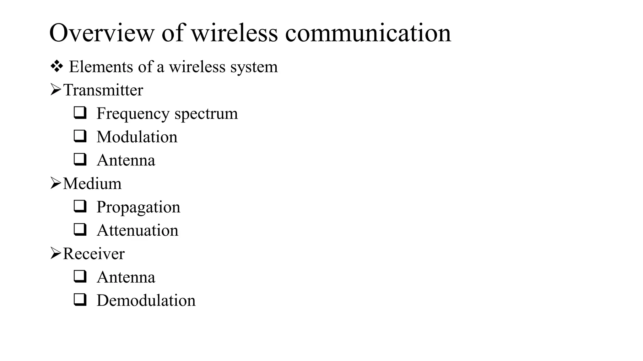
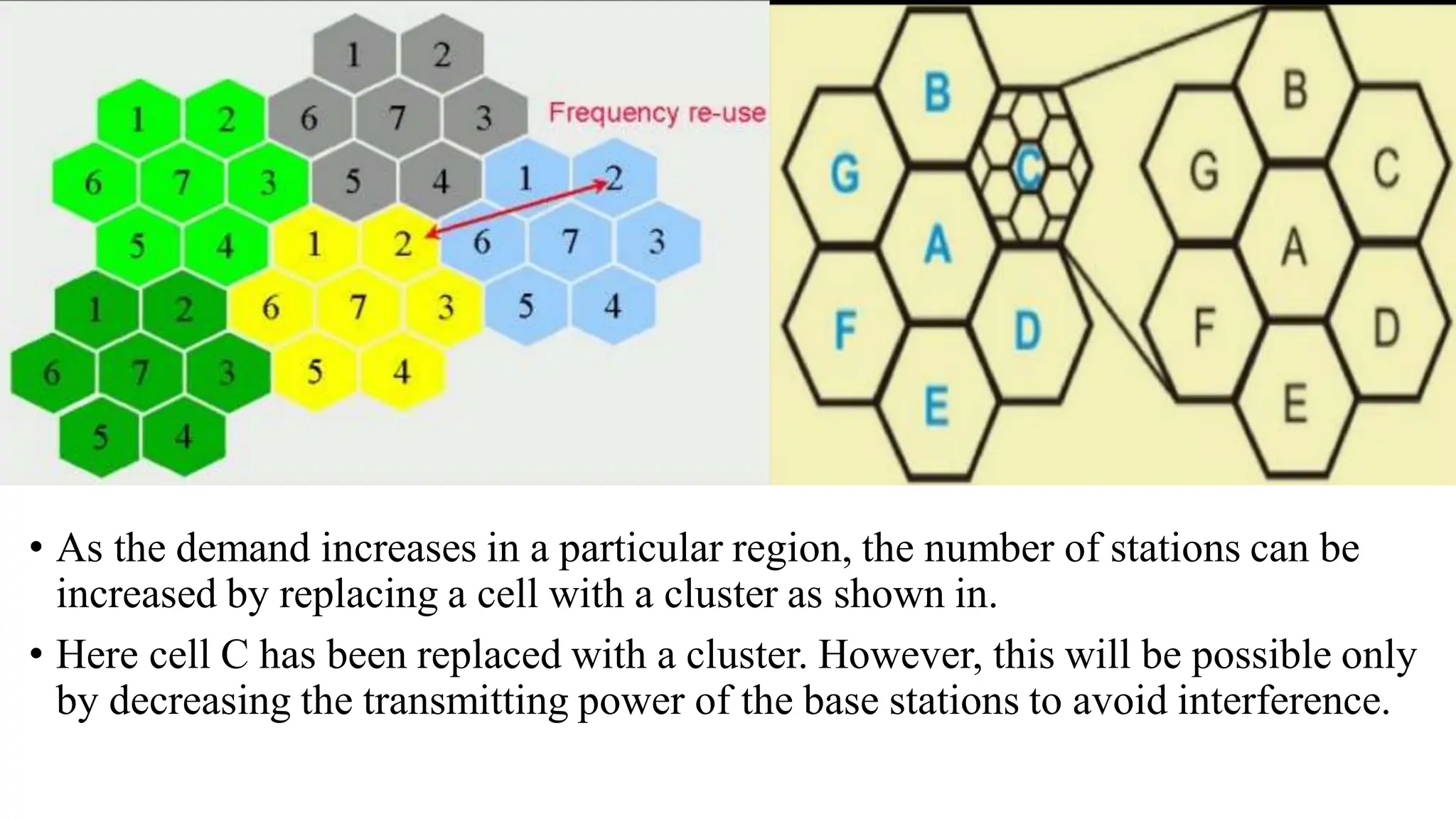
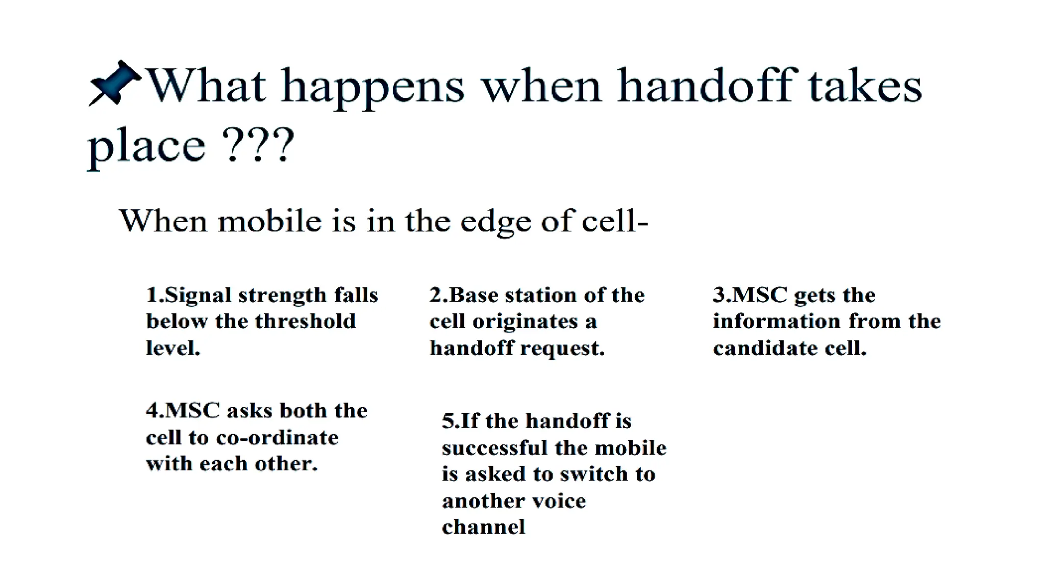
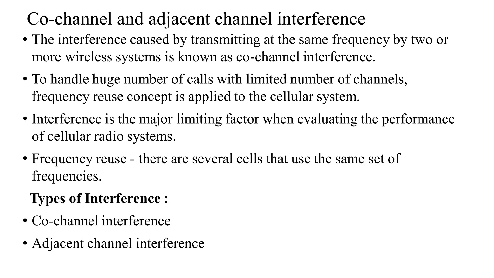
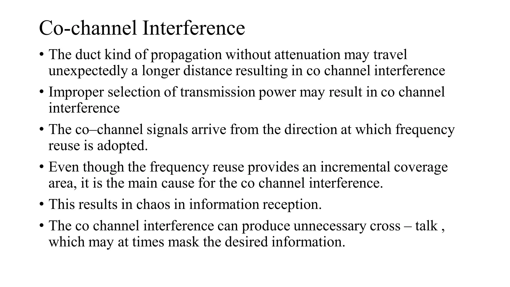
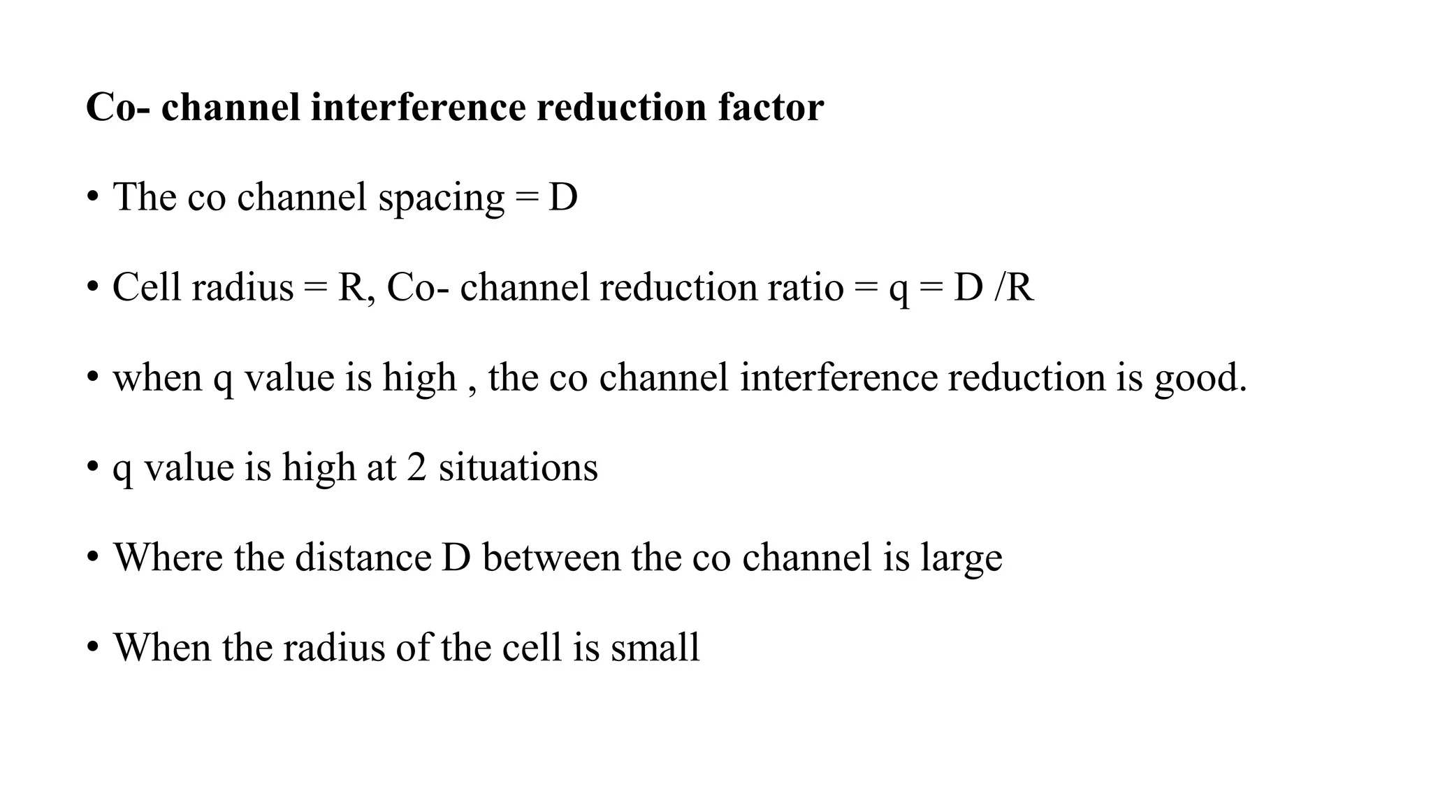
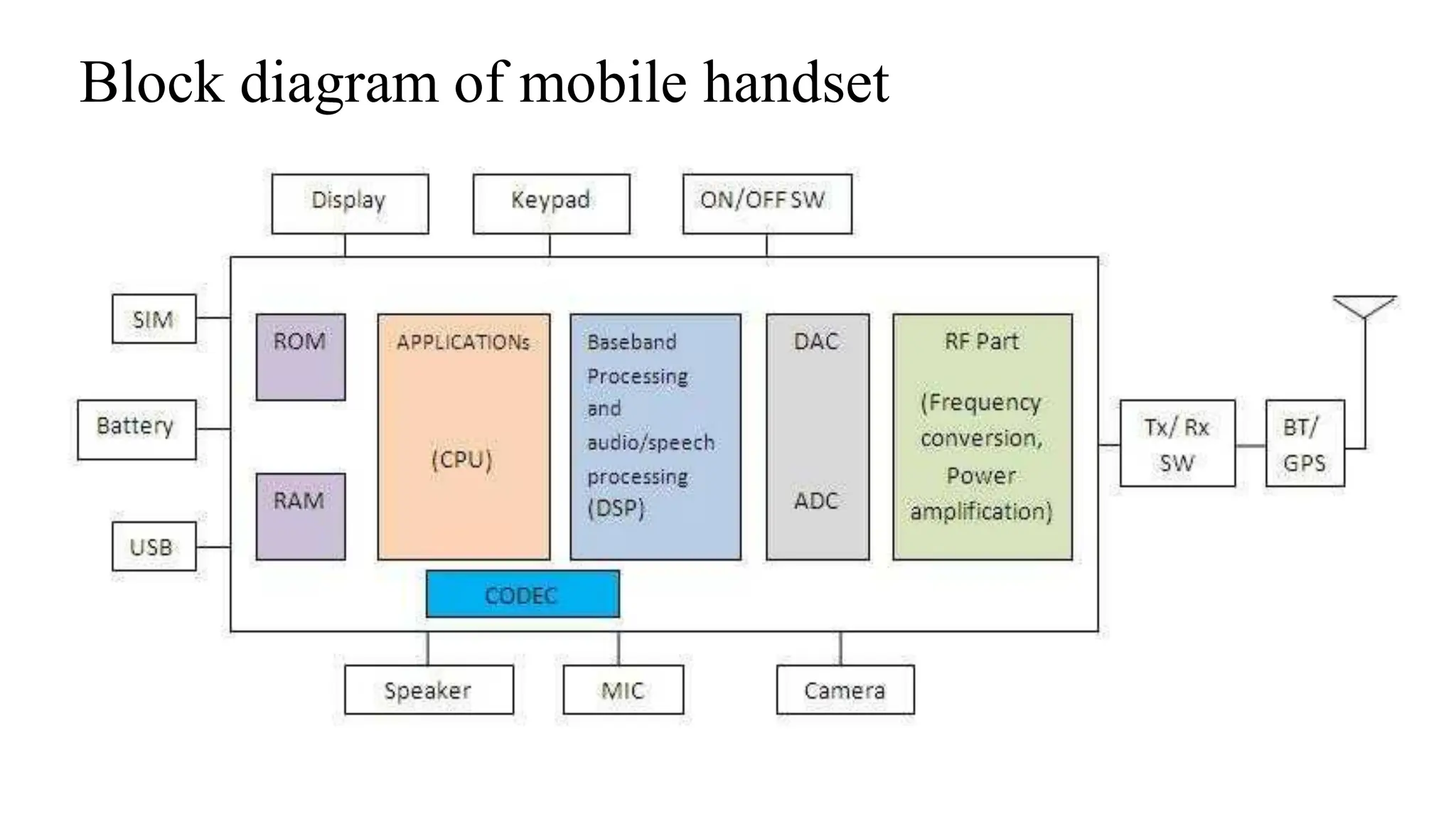
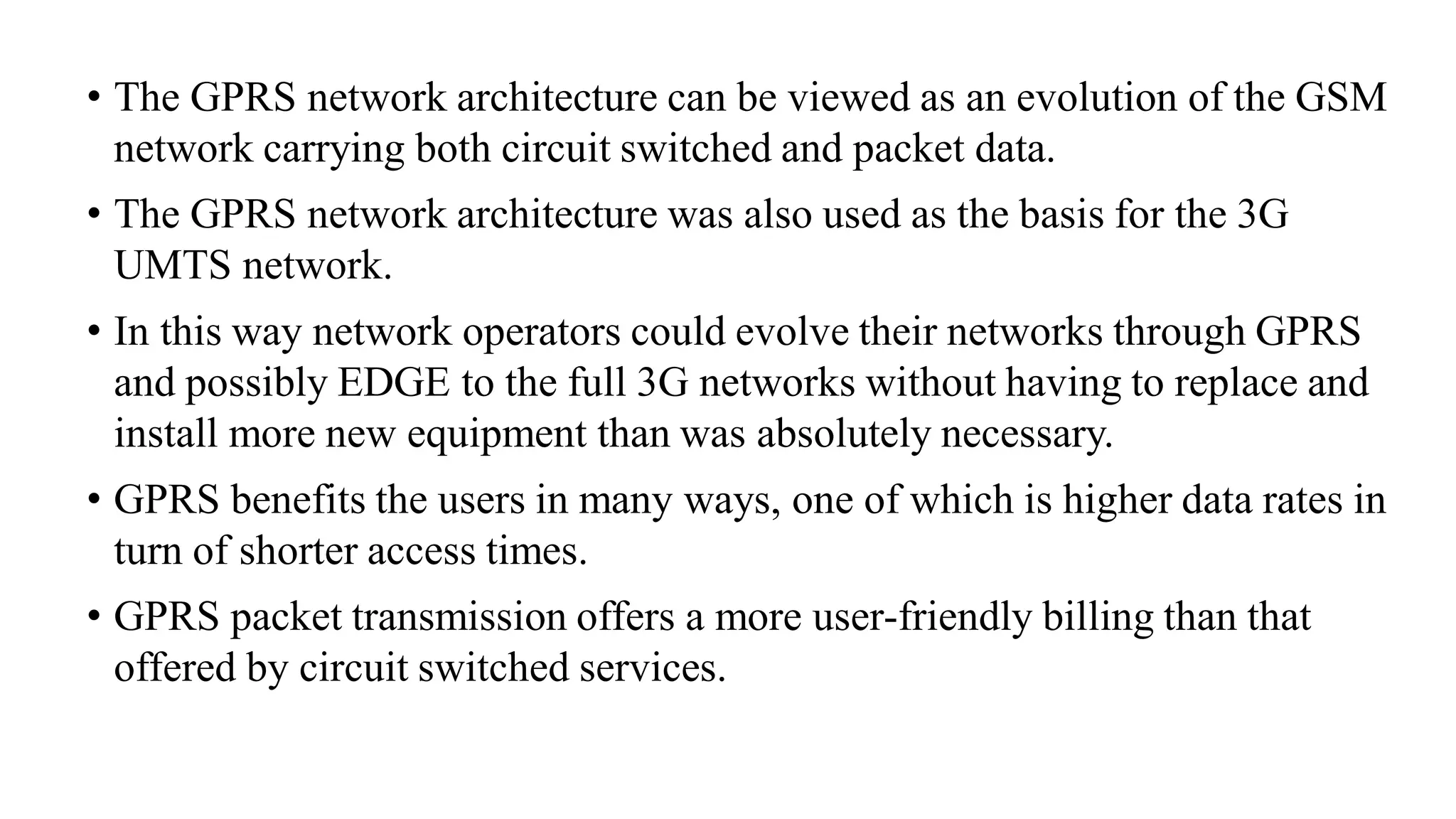
SlideShare a Scribd company logo
1 of 83
Download to read offline
SY B.Sc. (C.S.) Sem-IV
Electronics Paper-II
Wireless Communication and Internet of Things
ELC- 242
Prepared By:
Shubhangi Gaikar
Syllabus
• Unit1:
Wireless Communication: Cellular Telephony
Overview of wireless communication,
Introduction of cellular telephony system: Frequency reuse, handoff
strategies, Co-channel and adjacent channel interference, block diagram
of mobile handset
Overview of Cellular Telephony generations: 1G to 5G,3G (W-CDMA,
Universal Mobile Telecommunications System (UMTS)), 4G(LTE)
Long Term Evolution
GSM: architecture, frame structure, mobility management,
GPRS : architecture, application
Unit 2 : Short Range Wireless Technologies
and Location Tracking
Short range Technologies :
Bluetooth: Bluetooth architecture, Bluetooth protocol stack, Bluetooth
frame structure
Zigbee: Architecture, topologies, applications, Z wave: Protocol
architecture, applications
RFID: working of RFID system, types of RFID tags, RFID frequencies,
applications
Location Tracking: GPS system: components of GPS system (space
segment, control segment, user segment), GPS receiver, Applications
Unit 3: IoT Architecture
• Introduction to IOT : Evolution of IOT, M2M and/or IOT, Seven layer
architecture of IoT, Role of cloud in IoT, cloud topologies, Cloud
access, Protocols in IoT, Cross connectivity across IoT system
components:
• Device to Gateway-short range Wireless: cellphone as gateway,
dedicated wireless Access points
• Gateway to cloud: Long range connectivity, (wired, cellular, Satellite,
WAN)
• Direct Device to Cloud connectivity ,
• Networking technologies: Low power local area networking
(LPLAN), Low power wide area networking (LPWAN) technologies,
comparison of LoRa, Sigfox NB-IoT, Cat –M.
Unit 4: IoT Applications
• Application domains,
• Challenges in IoT : Power consumption, Physical security, durability,
Secure Connectivity, Secure Data Storage, Data volume, Scalability
Case studies:
• Case Study 1: Smart Irrigation system for Agricultural field
• Case Study 2: Home Automation
• Case Study 3: Smart Cities
Recommended books:
• Wireless Communications Principles and Practice, Rappaport, Pearson
publication
• Mobile Communications, Jochen Schiller, Pearson publication
• Internet of Things : Principles and Paradigms, Rajkumar Buyya and
Dastjerdi, MK publishers
• Internet of Things, Mayur Ramgir, Pearson publication
Unit 1
Wireless Communication: Cellular Telephony
Overview of wireless communication
❖ Elements of a wireless system
➢Transmitter
❑ Frequency spectrum
❑ Modulation
❑ Antenna
➢Medium
❑ Propagation
❑ Attenuation
➢Receiver
❑ Antenna
❑ Demodulation
Wireless Services
➢ Telemetry control & traffic control systems
➢ Infrared & ultrasonic remote control devices
➢ Professional LMR (Land Mobile Radio) & SMR (Specialized Mobile Radio)
Used by business, industrial & public safety entities
➢ Consumer 2-way radio
➢ Airband & radio navigation equipment
➢ Amateur Radio Service (Ham radio) ( non-commercial exchange
messages, wireless experimentation)
➢ Cellular telephones & pagers
➢ Global Positioning System (GPS)
➢ Cordless computer peripherals
➢ Cordless phones
➢ Satellite television
Elements of wireless communication
Introduction of cellular telephony system
❖ Today’s Cellular Telephone Systems
➢History
• In 1895, the telephone was invented by MARCONI demonstrated the first
radio transmission from the Isle of Wight to a tugboat 18 miles away, and
radio communications was born.
• Today most radio systems transmit digital signals composed of binary bits,
where the bits are obtained directly from a data signal or by digitizing an
analog voice or music signal.
Cellular Telephone Systems
• Cellular telephone systems are designed to provide two-way voice.
• Cellular systems were initially designed for mobile terminals inside
vehicles with antennas mounted on the vehicle roof.
• The basic feature of the cellular system is frequency reuse.
• In a cellular system, the signal from a mobile unit (cell phone) to a base
station is transmitted by radio waves through the air, instead of through
metallic wires.
• However, the signal from the base station is sent to a mobile switching
center and possibly to a telephone central office through electrical wires.
• The antenna at the base station converts the radio waves to electrical
signals and circuits in the base station send the signal to the appropriate
mobile switching center.
Cell concept
• Initial cellular system designs were mainly driven by the high cost of base
stations, about one million dollars each. For this reason early cellular systems used
a relatively small number of cells to cover an entire city or region.
• The cell base stations were placed on tall buildings or mountains and transmitted
at very high power with cell coverage areas of several square miles.
• These large cells are called macrocells.
• Signals propagated out from base stations uniformly in all directions, so a mobile
moving in a circle around the base station would have approximately constant
received power.
• Cellular telephone systems are now evolving to smaller cells with base stations
close to street level or inside buildings transmitting at much lower power.
• These smaller cells are called microcells or picocells, depending on their size.
• In a cellular radio system, a land area to be
supplied with radio service is divided into
regular shaped cells, which can be hexagonal,
square, circular or some other regular shapes.
• Each of these cells is assigned multiple
frequencies (f1 - f6 ) which have corresponding
radio base stations.
• The group of frequencies can be reused in other
cells
• Cellular Concept is used to increase both
coverage and capacity
FREQUENCY REUSE CONCEPT
• Cellular telephone systems rely on an intelligent allocation and reuse of
channels. Each base station is given a group of radio channels to be used within a
cell.
• Base stations in neighboring cells are assigned completely different set of
channel frequencies.
• By limiting the coverage areas, called footprints, within cell boundaries, the
same set of channels may be used to cover different cells separated from one
another by a distance large enough to keep interference level within tolerable
limits.
• Cells with the same letter use the same set of frequencies, called reusing cells.
• N cells which collectively use the available frequencies (S = k.N) is known as
cluster.
• As the demand increases in a particular region, the number of stations can be
increased by replacing a cell with a cluster as shown in.
• Here cell C has been replaced with a cluster. However, this will be possible only
by decreasing the transmitting power of the base stations to avoid interference.
TRASMITTING & RECEIVING
• Transmitting involves the following steps:
• A caller enters a 10-digit code (phone number) and presses the send button.
• The MS scans the band to select a free channel and sends a strong signal to send
the number entered.
• The BS relays the number to the MSC.
• The MSC in turn dispatches the request to all the base stations in the cellular
system.
• The Mobile Identification Number (MIN) is then broadcast over all the forward
control channels throughout the cellular system. It is known as paging.
• The MS responds by identifying itself over the reverse control channel.
• The BS relays the acknowledgement sent by the mobile and informs the MSC
about the handshake.
• The MSC assigns an unused voice channel to the call and call is established.
Receiving involves the following steps:
• All the idle mobile stations continuously listens to the paging signal to
detect messages directed at them.
• When a call is placed to a mobile station, a packet is sent to the
receiver’s home MSC to find out where it is.
• A packet is sent to the base station in its current cell, which then sends
a broadcast on the paging channel.
• The receiver MS responds on the control channel.
• In response, a voice channel is assigned and ringing starts at the MS.
HANDOFF
• At any instant, each mobile station is logically in a cell and under the
control of the cell’s base station.
• When a mobile station moves out of a cell, the base station notices the
MS’s signal fading away and requests all the neighboring BSs to
report the strength they are receiving.
• The BS then transfers ownership to the cell getting the strongest signal
and the MSC changes the channel carrying the call.
• The process is called handoff.
• The term handover or handoff refers to the process of transferring an
ongoing call or data session from one channel connected to the core
network to another.
• When the phone is moving away from the area covered by one cell and
entering the area covered by another cell the call is transferred to the second
cell in order to avoid call termination when the phone gets outside the range
of the first cell.
• There are two types of handoff; Hard Handoff and Soft Handoff.
• In a hard handoff, which was used in the early systems, a MS communicates
with one BS.
• As a MS moves from cell A to cell B, the communication between the MS
and base station of cell A is first broken, before communication starts
between the MS and the base station of B.
• As a consequence, the transition is not smooth. For smooth transition from
one cell (say A) to another (say B), an MS continues to talk to both A and B.
• As the MS moves from cell A to cell B, at some point the communication is
broken with the old base station of cell A. This is known as soft handoff.
Handoff Strategies
• Handoff is encouraged to maintain call quality as subscribers move in and out of range of base station.
• Before handoff the base station monitors the signal level for a certain period of time.
• Avoid unnecessary handoff by measuring the signal strength and ensuring the handoff is completed
before the termination of call.
• Who makes a decision for handoff?
• Three handoff detection schemes: –
• Mobile-controlled handoff (MCHO) • MS continuously monitors the signals of the surrounding BSs
and initiates handoff process when some criteria are met
• Network-controlled handoff (NCHO) • The surrounding BSs measure the signal from the MS, and the
network initiates the handoff process when some criteria are met
• Mobile-assisted handoff (MAHO) • The network asks the MS to measure the signal from the
surrounding BSs and report back to old BS. The network makes the handoff decision based on reports
from the MS
Handoff should be performed under the following circumstances
The call will be dropped when there is an excessive delay in
MSC due to huge traffic in assigning handoff.
The call will be dropped if no channels are available.
Co-channel and adjacent channel interference
• The interference caused by transmitting at the same frequency by two or
more wireless systems is known as co-channel interference.
• To handle huge number of calls with limited number of channels,
frequency reuse concept is applied to the cellular system.
• Interference is the major limiting factor when evaluating the performance
of cellular radio systems.
• Frequency reuse - there are several cells that use the same set of
frequencies.
Types of Interference :
• Co-channel interference
• Adjacent channel interference
Co-channel Interference
• The duct kind of propagation without attenuation may travel
unexpectedly a longer distance resulting in co channel interference
• Improper selection of transmission power may result in co channel
interference
• The co–channel signals arrive from the direction at which frequency
reuse is adopted.
• Even though the frequency reuse provides an incremental coverage
area, it is the main cause for the co channel interference.
• This results in chaos in information reception.
• The co channel interference can produce unnecessary cross – talk ,
which may at times mask the desired information.
Co- channel interference reduction factor
• The co channel spacing = D
• Cell radius = R, Co- channel reduction ratio = q = D /R
• when q value is high , the co channel interference reduction is good.
• q value is high at 2 situations
• Where the distance D between the co channel is large
• When the radius of the cell is small
Adjacent channel interference
• Adjacent channel interference (ACI) is interference between links that
communicate geographically close to each other using neighboring
frequency bands.
• Adjacent channel interference results also from imperfect receiver
filters.
• This type of interference occurs when the information on the adjacent
channel seeps into pass band of the channel being transmitted, due to
which performance of the main channel is degraded.
• Channel 1 is adjacent to channel 2, which is adjacent to channel 3, and
so on.
• Adjacent channel interference happens when two or more access
points using overlapping channels are located near enough to each
other that their coverage cells physically overlap.
• Adjacent channel interference can severely degrade throughput in a
wireless LAN.
Sources of Interference
• Another mobile in the same cell.
• A call in progress in the neighboring cell.
• Other BS’s operating in the same frequency band.
• Any non-cellular system which accidently leaks energy into the cellular
frequency band.
• Interference on voice channels causes cross talk due to an undesired
transmission.
Causes of Adjacent Channel Interference:
• Poor frequency control. It occurs when one or both of the adjacent channels are
broadcast with too much or too little power behind them.
• Inadequate filtering. It occurs when the receiving channel does not have the
proper modulation to filter out the interfering signal.
Avoidance procedure
• Adjacent channel interference can be minimized through careful
filtering and channel assignments.
• By keeping the frequency separation between each channel in a given
cell as large as possible, the adjacent interference may be reduced
considerably
Block diagram of mobile handset
• The hardware of the handset sub-divides into two main categories.
• The first part comprises of more mechanical parts of the handset
like– the display, camera(s), keypad (if it’s not a touchscreen
phone), antenna, loudspeaker, microphone, buzzer (for alerts), SIM
card, external memory card connectors, serial interface and battery
charging connectors, the button battery and its connector, and
various backlights for the display and keypad. These together are
often known as the peripheral components.
• The second category includes the printed circuit board (PCB) and
many electronic components mounted on both surfaces
Printed circuit board
• In PCB design, major functions of the handset are group together into digital
baseband, application processing, radio (RF), auxiliary modem and memory.
Digital baseband
• The digital baseband chipset is responsible for processing all of the
communication with the cellular network, based on data signals sent to and
received from the air interface via the radio chipset.
• A modern digital baseband chipset contains multiple processors, both
microprocessors and DSP (digital signal processors)
• Processors provide the computing capabilities for software to execute –
processing, memory, timing and peripheral interfacing (or I/O – input/output).
• Until the early 2000s, all the high-end devices used a single microprocessor
core to run the protocol software as well as all of the application software
required, with a separate DSP to handle the physical layer software.
• With the rise in multimedia capabilities a tipping point was reached where the
required level of real-time performance could not be achieved with a single
processor solution.
• For a few chipset iterations, improvements were achieved by packaging the
low-level camera control and decode features in to one chip
• Some chipset manufacturers also created discrete logic to encode and decode
audio and video streams, and built this logic into their baseband chipsets.
• Despite these efforts, a well established trend now is to separate the “modem”
features into one modem processor, and application and multimedia functions
into another application processor (AP).
Radio
• The radio section of the handset design is housed in metal shielding to reduce
electromagnetic interference of the radio from unwanted signals.
• In a modern radio design, much of the radio functionality is contained within a single
radio chipset.
• A typical list of air interfaces which could be supported in the most advanced
combined radio chipsets would include:
• UMTS Universal Mobile Telecommunications Service /HSDPA High Speed Downlink Packet Access/HSUPA (850, 900,
1900, 2100 MHz).
• GSM/EDGE (enhanced data rates for GSM evolution) (850, 900, 1800, 1900 MHz).
• CDMA EV-DO (evolution data optimized) Rev. A (800, 1900 MHz).
• The first radio chipsets supported a single radio band, and then over the time
added two, three and four other bands.
• With the transition from 2G to 3G networks, it has remained important for
network operators to provide legacy support for their customers.
e.g. such that if 3G network coverage is not available, then the handset can “fall
back” to a 2G mode of operation.
• Early 3G handsets contained two discrete radio chipsets – one for 2G and
another for 3G, which was one of the factor in the high cost of early 3G
handsets.
• In addition to the radio chipset on the radio section of the handset PCB, the
other key component is the power amplifier (PA) chip.
• The PA is responsible for magnifying the power strength of the RF signal to be
transmitted, quickly and accurately, before it reaches the antenna.
• A contemporary handset may support a number of other radio standards such as
an FM receiver, Bluetooth, Wi-Fi and GPS.
• These features are provided via an auxiliary connectivity chip.
• Some auxiliary modem functions have their digital communications
capabilities built into the digital baseband, which reduces the number of chip
packages on the PCB which leads to a smaller, perhaps lower cost, design.
Memory
• Key component on the baseband portion of the handset PCB is memory.
• Depending on the digital chipset, some memory could be pre-integrated in the
chipset design or prepackaged within the chipset packaging.
• In order to support different handset variants with different memory
requirements, there are discrete memory components provided separately on
the PCB.
• Two types of memory are required.
• First type is memory to store software program code and static data, it is
known as non-volatile memory, and requires an electrical current to erase
and re-program the memory.
• Second type of memory is RAM, which is used to store temporary data
required by the handset software as “working memory,”.
• There are two main forms of RAM available – static RAM (SRAM) and
dynamic RAM (DRAM).
• SRAM is more expensive to produce, but is faster to access and requires
less power than DRAM. SRAM is therefore very suitable for cache
memory, where speed of access is key.
• Whereas DRAM is more suited for storing larger quantities of data for
longer periods of time.
Overview of Cellular Telephony generations
• 0th Generation
• Pre-cell phone mobile telephony technology in 1970s, such as
radio telephones that some had in cars before the arrival of cell
phones.
• Communication was possible through voice only.
• These mobile telephones were usually mounted in cars or
trucks.
• Technologies :
• PTT(Push to Talk)
• MTS (Mobile Telephone System)
• IMTS (Improved MTS)
First Generation Cellular Systems
• First generation (1G) of cellular systems introduced in the late 1970s and early 1980s
• Evolved out of the growing number of mobile communication users
• The use of semiconductor technology and microprocessors made mobile devices smaller and
lighter
• It's Speed was up to 2.4kbps.
• 1G systems were based on analogue communication in the 900MHz frequency range
• This system is used for Voice transmission only – easy to tap
• The most prominent 1G systems are
• Advanced Mobile Phone Systems (AMPS) - America
• Nordic Mobile Telephone (NMT) - France
• Total Access Communications System (TACS) – UK
• Jan 1985 Vodafone introduced the TACS system
• Splits allocated spectrum into 30
channels, each channel is 30kHz
• Allocates a single channel to each
established phone call
• The channel is agreed with the
serving base-station before
transmission takes place on agreed
and reserved channel
• Channel used by device to transmit
and receive on this channel
• Ineffective methods since each
analogue channel can only be used
by one user at a time
• FDMA does not take full
advantage of available spectrum
Drawbacks of 1G System
• Poor Voice Quality
• Poor Battery Life
• Large Phone Size
• No Security
• Limited Capacity
• Poor Handoff Reliability
Frequency Division Multiple Access (FDMA)
Second Generation Cellular Systems
• Development driven by the need to improve speech quality, system capacity, coverage and security
• First system that used digital transmission
• Examples of Second Generation (2G) cellular systems ...
• Digital AMPS (D-AMPS) (Advanced Mobile Phone Service) in the US,
• Personal Digital Communication (PDC) in Japan,
• Intrim Standard `94 (IS-94) in Korea and the US
• Global System for Mobile Communication (GSM)
• The GSM standard was defined by ETSI (European Telecommunications Standards Institute) in
1989
• Originally called “ Groupe Spéciale Mobile which later changed to the English version
• A majority of countries over the world have adopted GSM900 and the GSM1800 which are all based
on the same original GSM specification.
• The US uses an additional GSM 1900
Drawbacks of 2G
• 2G technology refers to the 2nd generation which is based on GSM.
• It was launched in Finland in the year 1991.
• 2G network use digital signals.
• It’s data speed was up to 64kbps.
• Features Includes:
• It enables services such as text messages, picture messages and MMS (multi
media message).
• It provides better quality and capacity .
▪ 2G requires strong digital signals to help mobile phones work. If there is no
network coverage in any specific area , digital signals would weak.
▪ These systems are unable to handle complex data such as Videos.
2.5G Technology
• 2.5G is a technology between the second (2G) and third (3G) generation of
mobile telephony.
• 2.5G is sometimes described as 2G Cellular Technology combined with
GPRS.
• Features Includes:
• Phone Calls
• Send/Receive
• E-mail Messages
• Web Browsing
• Speed : 64-144 kbps
• Camera Phones
• Take a time of 6-9 mins to download a 3 mins Mp3 song
3rd GENERATION
• 2G networks were built mainly for voice data and slow transmission. Due to
rapid changes in user expectation, they do not meet today's wireless needs.
• 3G networks provide the ability to transfer voice data and non-voice data over
the same network simultaneously.
• Applications : Internet, e-mail, fax, e-commerce, music, video clips, and
videoconferencing.
• The aim of the 3G is to allow for more coverage and growth with minimum
investment.
• 3G technology refer to third generation which was introduced in year 2000s.
• Data Transmission speed increased from 144kbps- 2Mbps.
• Typically called Smart Phones and features increased its bandwidth and data
transfer rates to accommodate web-based applications and audio and video files.
3G UMTS
• Universal Mobile Telecommunications System (UMTS)
• UMTS is an upgrade from GSM via GPRS or EDGE.
• Combines the infrastructure of the GSM network with superior technology
of the CDMA air interface. The standard was referred to as IMT-2000.
• The standardization work for UMTS is carried out by Third Generation
Partnership Project (3GPP)
• Data rates of UMTS are:
– 144 kbps for rural
– 384 kbps for urban outdoor
– 2048 kbps for indoor and low range outdoor
• UMTS-specific network elements—User equipment (UE) and UMTS
terrestrial radio access network (UTRAN) elements.
• W-CDMA is the most common radio interface for UMTS systems.
• W-CDMA uses 5MHz of bandwidth for each channel.
• Several thousand users can be supported in each cell site.
• Offers 11Mbps download speed.
• Fast power control (PC) – Reduces the impact of channel fading and
minimizes the interference.
• Soft handover – Improves coverage, decreases interference.
• Market share for WCDMA is growing rapidly – More than 340 million
WCDMA subscribers
• WCDMA Operates in the same manner as the CDMA used in the US
• CDMA allows multiple users to communicate at the same time over the same
frequency
• Each of the devices is given a “Chipping code” this is known by the device
and the base station.
• This chipping code is then used to identify the signal and allows the BS to
receive the signal
• The chipping code is used to adjust the frequency of data transferred during
the transfer
• The essential point of CDMA is the use of power control
• W-CDMA – Wideband CDMA operates the same but this takes place over a
wider area of frequency
• UMTS uses 5MHz for the signal
• CDMA (narrowband) uses 200 KHz
• These communications are secure by the nature that unless the chipping code
is known, the sequence of the data can not be known
• Communications can take place as soon as the device is ready and frequency
reuse factor is now one
3.5G (HSPA)
• High Speed Packet Access (HSPA) is an amalgamation of two mobile
telephony protocols, High Speed Downlink Packet Access (HSDPA) and
High Speed Uplink Packet Access (HSUPA), that extends and improves
the performance of existing WCDMA protocols.
• 3.5G introduces many new features that will enhance the UMTS
technology in future. 1xEV-DV already supports most of the features that
will be provided in 3.5G.
These include:
- Adaptive Modulation and Coding
- Fast Scheduling
- Backward compatibility with 3G
- Enhanced Air Interface
4G TECHNOLOGY (LTE)
• 4G technology refer to or short name of fourth Generation which was started from late 2000s.
• Capable of providing 100Mbps – 1Gbps speed.
• The next generations of wireless technology that promises higher data rates and expanded multimedia
services.
• Capable to provide speed 100Mbps-1Gbps. High QOS (Quality of Service) and High Security Provide any
kind of service at any time as per user requirements, anywhere.
• LTE stands for “Long Term Evolution”
• Fourth-generation (4G) cellular technology from 3GPP
• Deployed worldwide
• 4G LTE: First global standard
– Increased speed
– IP-based network (All circuits are gone/fried!)
– New air interface: OFDMA (Orthogonal Frequency-Division Multiple Access), MIMO (multiple
antennas)
• Also includes duplexing, timing, carrier spacing, coding...
– New service paradigm (e.g., VoLTE)
2G
Telecomm
Infrastructure
IP-based Internet
• Circuit-
switching
for voice
• Packet-
switching for
everything
• IP-based
3G 4G
• Circuit-switching
for voice
• Packet-switching
for data
Network Architecture Evolution
5G Technology
• 5G simply refers to the next and newest mobile wireless standard based on the IEEE 802.11ac standard
of broadband technology.
• 5G aims at a higher capacity than current 4G LTE, allowing a higher number of mobile broadband users
per area unit.
• 5G research and development also aim at the improved support of machine to machine communication,
also known as the Internet of things.
• aiming at a lower cost, lower battery consumption, and lower latency and to increase the security and
connectivity for a large community.
• 5G will utilize the advance access technologies such as Beam Division Multiple Access (BDMA) and
Non and quasi-orthogonal or Filter Bank Multicarrier (FBMC) Multiple Access.
• 5G operates on 3 different spectrum bands.
1. Low-band spectrum – Expect peak speeds up to 100Mbps
2. mid-band spectrum – Expect peak speeds up to 1Gbps
3. high-band spectrum – Expect peak speeds up to 10Gbps
The following are the key takeaways of the 5G network:
• High & increased peak bit rate (Up to 10Gbps connections to endpoints in
the field)
• Larger data volume per unit area (i.e. high system spectral efficiency)
• High capacity to allow more devices connectivity concurrently and
instantaneously (100 percent coverage)
• More bandwidth
• Lower battery consumption
• Better connectivity irrespective of the geographic region where you are in
• A larger number of supporting devices (10 to 100x number of connected
devices)
• Lower cost of infrastructural development
• Higher reliability of the communications (One millisecond end-to-end
round trip delay)
GSM Architecture
• Global System for Mobile (GSM) is a second generation cellular
standard developed to cater voice services and data delivery using digital
modulation .
• Developed by Group Spéciale Mobile (founded 1982) which was an
initiative of CEPT ( Conference of European Post and
Telecommunication )
• Under ETSI, GSM is named as “ Global System for Mobile
communication “ in 1989
• Full set of specifications phase-I became available in 1990
• Phase 2 of the GSM specifications occurs in 1995. Coverage is extended
to rural areas.
Integrated Services Digital Network (ISDN)
packet switched public data network (PSPDN)
Circuit Switched Public Data network (CSPDN)
• Um interface The "air" or radio interface standard that is used for
exchanges between a mobile (ME) and a base station (BTS / BSC). For
signaling, a modified version of the ISDN LAPD, known as LAPDm is
used.
• Abis interface This is a BSS internal interface linking the BSC and a BTS,
and it has not been totally standardized. The Abis interface allows control of
the radio equipment and radio frequency allocation in the BTS.
• A interface The A interface is used to provide communication between the
BSS and the MSC. The interface carries information to enable the channels,
timeslots and the like to be allocated to the mobile equipment's being
serviced by the BSSs. The messaging required within the network to enable
handover etc. to be undertaken is carried over the interface.
• Mobile Station (MS)
• Mobile Equipment (ME)
• Subscriber Identity Module (SIM)
• Base Station Subsystem (BSS)
• Base Transceiver Station (BTS)
• Base Station Controller (BSC)
• Network Switching Subsystem(NSS)
• Mobile Switching Center (MSC)
• Home Location Register (HLR)
• Visitor Location Register (VLR)
• Authentication Center (AUC)
• Equipment Identity Register (EIR)
MOBILE EQUIPMENT
• Portable, vehicle mounted, hand held device
• Uniquely identified by an IMEI (International Mobile Equipment Identity)
• Voice and data transmission
• Monitoring power and signal quality of surrounding cells for optimum handover
Power level : 0.8W – 20 W
• 160 character long SMS
SUBSCRIBER IDENTITY MODULE(SIM)
• Smart card contains the International Mobile Subscriber Identity (IMSI)
• Allows user to send and receive calls and receive other subscribed services
• Protected by a password or PIN
• Can be moved from phone to phone – contains key information to activate the
phone
• SIM has a significant impact on the way that a user transacts with the service
provider. –For instance, determines charging, roaming etc.
BASE STATION SUBSYSTEM (BSS)
• Base Station Subsystem is composed of two parts that communicate
across the standardized Abis interface allowing operation between
components made by different suppliers
• Base Transceiver Station (BTS)
• Base Station Controller (BSC)
BASE TRANSCEIVER STATION (BTS):
• Encodes, encrypts, multiplexes, modulates and feeds the RF signals to
the antenna.
• Communicates with Mobile station and BSC
• Consists of Transceivers (TRX) units
BASE STATION CONTROLLER (BSC)
• Manages Radio resources for BTS
• Assigns Frequency and time slots for all MS’s in its area
• Handles call set up
• Handover for each MS
• It communicates with MSC and BTS
NETWORK SWITCHING SUBSYSTEM(NSS)
The system contains the following functional units
▪ Mobile Switching Center (MSC)
▪ Home Location Register (HLR)
▪ Visitor Location Register (VLR)
▪ Authentication Center (AUC)
▪ Equipment Identity Register (EIR)
MOBILE SWITCHING CENTER (MSC)
• Heart of the network
• Manages communication between GSM and other networks
• Billing information and collection
• Mobility management
Registration
Location Updating
Inter BSS and inter MSC call handoff
HOME LOCATION REGISTERS (HLR)
• Stores information about each subscriber that belongs to it MSC in permanent
and temporary fashion.
• As soon as mobile subscriber leaves its current local area, the information in the
HLR is updated.
• Database contains IMSI, Mobile Station International Subscriber
Director Number (MSISDN), prepaid/ postpaid, roaming restrictions, subscriber
address, service type, current locations, forwarding address,
authentication/ciphering keys, and billings information supplementary services.
• HLR is the reference database that permanently stores data related to
subscribers, including subscriber’s service profile, location information, and
activity status.
VISITOR LOCATION REGISTERS (VLR)
• Temporary database software similar to the HLR identifying the mobile
subscribers visiting inside the coverage area of an MSC.
• Assigns a Temporary Mobile Subscriber Identity (TMSI) to each MS entering the
VLR area which keeps on changing.
• The visitor location register maintains information about mobile subscriber that is
currently physically in the range covered by the switching center
• When a mobile subscriber roams from one LA (Local Area) to another, current
location is automatically updated in the VLR.
• When a mobile station roams into a new MSC area, if the old and new LA’s are
under the control of two different VLRs, the VLR connected to the MSC will
request data about the mobile stations from the HLR.
• The entry on the old VLR is deleted and an entry is created in the new VLR by
copying the database from the HLR. Database contains IMSI, MSISDN, Location
Area, authentication key
AUTHENTICATION CENTER (AUC)
• The AuC is a protected database that contains the secret key also
contained in the user's SIM card.
• It is used for authentication and for encoding on the radio channel.
• Contains the algorithms for authentication as well as the keys for
encryption.
• Protects network operators from fraud.
• Situated in special protected part of the HLR.
• The AUC protects network operators from different types of fraud
found in today's cellular world.
EQUIPMENT IDENTITY REGISTER (EIR)
• Stores all devices identifications registered for this network.
• Database that is used to track handsets using the IMEI (International Mobile Equipment
Identity)
• An IMEI is marked as invalid if it has been reported stolen or is not type approved.
• Prevents calls from stolen, unauthorized or defective mobile devices.
OPERATION AND MAINTENANCE CENTRE (OMC)
• The centralized operation of the various units in the system and functions needed to
maintain the subsystems.
• Dynamic monitoring and controlling of the network.
• Functions : - configuration management - fault report and alarm handling - performance
supervision/management - storage of system software and data
GSM Frame Structure
• GSM data structure is split into slots, frames, multiframes, superframes and
hyperframes to give the required structure and timing to the transmitted data.
• GSM frame structure enables the data to be organized in a logical fashion so
that the system is able to handle the data correctly.
• GSM frame structure comprises of the eight slots, each used for different users
within the TDMA system.
• The slots for transmission and reception for a given mobile are offset in time
so that the mobile does not transmit and receive at the same time.
• The basic GSM frame defines the structure upon which all the timing and
structure of the GSM messaging and signaling is based, the fundamental unit
of time is called a burst period.
• This burst lasts for approximately 0.577ms (15/26ms). Eight of these burst
periods are grouped into what is known as a TDMA frame. This lasts for
approximately 4.615ms (i.e.120/26ms)
GSM slots
Note: offset between transmit and receive
• The core of any radio based system is the format of the radio signal itself. The carrier is
modulated using a form of phase sift keying known as Gaussian Minimum Shift Keying
(GMSK).
• The nominal bandwidth for the GSM signal using GMSK is 200 kHz, i.e. the channel
bandwidth and spacing is 200 kHz.
• GSM uses a combination of both TDMA and FDMA techniques. The FDMA element
involves the division by frequency of the (maximum) 25 MHz bandwidth into 124 carrier
frequencies spaced 200 kHz apart.
• The carriers are then divided in time, using a TDMA scheme. This enables the different
users of the single radio frequency channel to be allocated different times slots.
• One physical channel is one burst period allocated in each TDMA frame.
• Basically the base station transmits two types of channels, namely traffic and control.
• Accordingly the channel structure is organized into two different types of frame, one for the
traffic on the main traffic carrier frequency, and the other for the control on the beacon
frequency.
GSM multiframes
• The GSM frames are grouped together to form multiframes and in this
way it is possible to establish a time schedule for their operation and the
network can be synchronized.
• 2 types of multiframes are mentioned below.
• Traffic multiframes
• Control multiframes
Mobility Management
• Mobility is very important in mobile communication, and can be classified as radio
mobility and network mobility.
• Radio mobility is mainly concerned with the handoff process.
• Network mobility deals with mobile location management (i.e., location and updating).
• Mobility management in wireless networks is primarily important for a network, in
order to enable subscriber mobility, which includes enabling the network to keep track
of a subscribers status and location in order to deliver calls to the subscriber.
• The key component to mobility management is the subscribers service profile, which is
a database record in the network that contains information about each subscriber.
• The data in the record is dynamic such as current location and status of subscriber and
permanent data such as service profile, International Mobile Subscriber Identity
(IMSI), etc., of the subscriber.
Mobility issues
• Radio resource management
• Location info management
• Security
• Temporary loss of connectivity with movement
• Scarce resources : Small devices, low battery power, small CPU, less
memory, light weight,….
• React to sudden change in environment due to bandwidth and other
resource changes????
• Mobility management generally deals with automatic roaming, authentication, and intersystem
handoff.
• Automatic roaming includes a set of network functions that allow the subscriber obtain service
outside the home service provider area.
• These functions are automatic and do not require special subscriber actions. Automatic
roaming functions are divided into:
• I. Mobile station (MS) service qualification II. MS location management III. MS state
management IV. Home location register (HLR) and VLR fault recovery
• The authentication process requires that the end users of the system are authenticated.
• Handoff is one of the essential features that guarantee the subscriber mobility in a mobile
network where the subscriber can move around.
• The handoff function allows the moving subscriber to maintain a connection.
• In simple terms the handoff functions works when a subscriber moves into a new cell a new
connection has to be established and the cell in which the subscriber left from has to be
disconnected.
GSM Network Element Modification or Upgrade Required for GPRS.
Mobile Station (MS) New Mobile Station is required to access GPRS services. These new terminals
will be backward compatible with GSM for voice calls.
BTS A software upgrade is required in the existing Base Transceiver Station(BTS).
BSC The Base Station Controller (BSC) requires a software upgrade and the
installation of new hardware called the packet control unit (PCU). The PCU
directs the data traffic to the GPRS network and can be a separate hardware
element associated with the BSC.
GPRS Support Nodes (GSNs) The deployment of GPRS requires the installation of new core network
elements called the serving GPRS support node (SGSN) and gateway GPRS
support node (GGSN).
Databases (HLR, VLR, etc.) All the databases involved in the network will require software upgrades to
handle the new call models and functions introduced by GPRS.
GPRS requires modifications to numerous GSM network elements as summarized below:
GPRS
Architecture
• General Packet Radio System is also known as GPRS is a third-generation step toward internet
access.
• GPRS provided a packet data capability for the 2G cellular systems, enabling the evolution of GSM to
provide a data capability.
• To allow the GPRS network to provide the packet data capability additional network entities are
required to be added to the overall architecture - two of the main entities are the GGSN and SGSN.
• A packet data network architecture is overlayed or added to the existing GSM architecture to provide
the data capability.
• The existing GSM network architecture is used to carry the circuit switched voice calls as well as the
network access, etc.
• The main new network architecture entities that were needed are:
• SGSN, Serving GPRS Support Node: The SGSN forms a gateway to the services within the network.
• GGSN Gateway GPRS Support Node: The GGSN, forms the gateway to the outside world.
• PCU, Packet Control Unit: The PCU detects whether data is to be routed to the packet switched or
circuit switched networks.
Serving GPRS Support Node (SGSN)
SGSN
•Functionally connected with BSC, physically can be at MSC or BSC site
•One for few BSCs or one (or few) per every BSC
•One SGSN can support BSCs of several MSC sites
•Main functions
• Authenticates GPRS mobiles
• Handles mobile’s registration in GPRS network
• Handles mobile’s mobility management
• Relays MO and MT data traffic
• TCP/IP header compression, V.42bis data compression, error control MS- SGSN (ARQ)
• Collect charging information of air interface usage
Gateway GPRS Support Node (GGSN)
GGSN
•Typically located at one of the MSC sites.
•One (or few) per operator.
•Main functions
• Interface to external data networks.
• Resembles to a data network router.
• Forwards end user data to right SGSN.
• Routes mobile originated packets to right destination.
• Filters end user traffic.
• Collects charging information for data network usage.
• Data packets are not sent to MS unless the user has activated the PDP address.
• The GGSN can be considered to be a combination of a gateway, router and
firewall as it hides the internal network to the outside.
• The GPRS network architecture can be viewed as an evolution of the GSM
network carrying both circuit switched and packet data.
• The GPRS network architecture was also used as the basis for the 3G
UMTS network.
• In this way network operators could evolve their networks through GPRS
and possibly EDGE to the full 3G networks without having to replace and
install more new equipment than was absolutely necessary.
• GPRS benefits the users in many ways, one of which is higher data rates in
turn of shorter access times.
• GPRS packet transmission offers a more user-friendly billing than that
offered by circuit switched services.
SYBSC(CS)_WCIOT_Sem-II-Unit 1 Overview of wireless communication.pdf

More Related Content

Similar to SYBSC(CS)_WCIOT_Sem-II-Unit 1 Overview of wireless communication.pdf

MOBILE COMPUTING Unit 3.pptx
MOBILE COMPUTING Unit 3.pptxMOBILE COMPUTING Unit 3.pptx
MOBILE COMPUTING Unit 3.pptxkarthiksmart21
 
Basics of wireless communication
Basics of wireless communicationBasics of wireless communication
Basics of wireless communicationRAVIKIRAN ANANDE
 
Introduction to wireless communication
Introduction to wireless communicationIntroduction to wireless communication
Introduction to wireless communicationramalakshmi54
 
cellular-communications
 cellular-communications cellular-communications
cellular-communicationsjhcid
 
Freq reuse detail.ppt
Freq reuse  detail.pptFreq reuse  detail.ppt
Freq reuse detail.pptjaveriazafeer
 
2_cellular_network of mobile computing explained
2_cellular_network of mobile computing explained2_cellular_network of mobile computing explained
2_cellular_network of mobile computing explainedbipik48002
 
Cellular communication
Cellular communicationCellular communication
Cellular communicationRahul Pandey
 
M & WC unit 1.pptx very good condition and success
M & WC unit 1.pptx very good condition and successM & WC unit 1.pptx very good condition and success
M & WC unit 1.pptx very good condition and success20EC040
 
MOBILE COMPUTING MODULE 1 CALICUT UNIVERSITY
MOBILE COMPUTING MODULE 1 CALICUT UNIVERSITYMOBILE COMPUTING MODULE 1 CALICUT UNIVERSITY
MOBILE COMPUTING MODULE 1 CALICUT UNIVERSITYArchanaArunNath
 
1.ec6801 introduction final
1.ec6801 introduction final1.ec6801 introduction final
1.ec6801 introduction finalramalakshmi54
 
cellular-communication
cellular-communicationcellular-communication
cellular-communicationjhcid
 
cellular.ppt
cellular.pptcellular.ppt
cellular.pptjakjak36
 
cellular.ppt
cellular.pptcellular.ppt
cellular.pptsemua
 
Unit 1-Introduction to Mobile Computing
Unit 1-Introduction to Mobile ComputingUnit 1-Introduction to Mobile Computing
Unit 1-Introduction to Mobile ComputingSwapnali Pawar
 

Similar to SYBSC(CS)_WCIOT_Sem-II-Unit 1 Overview of wireless communication.pdf (20)

CELLULAR MOBILE RADIO SYSTEMS
CELLULAR MOBILE RADIO SYSTEMSCELLULAR MOBILE RADIO SYSTEMS
CELLULAR MOBILE RADIO SYSTEMS
 
MOBILE COMPUTING Unit 3.pptx
MOBILE COMPUTING Unit 3.pptxMOBILE COMPUTING Unit 3.pptx
MOBILE COMPUTING Unit 3.pptx
 
Basics of wireless communication
Basics of wireless communicationBasics of wireless communication
Basics of wireless communication
 
Introduction to wireless communication
Introduction to wireless communicationIntroduction to wireless communication
Introduction to wireless communication
 
cellular-communications
 cellular-communications cellular-communications
cellular-communications
 
Freq reuse detail.ppt
Freq reuse  detail.pptFreq reuse  detail.ppt
Freq reuse detail.ppt
 
2_cellular_network of mobile computing explained
2_cellular_network of mobile computing explained2_cellular_network of mobile computing explained
2_cellular_network of mobile computing explained
 
Cellular communication
Cellular communicationCellular communication
Cellular communication
 
M & WC unit 1.pptx very good condition and success
M & WC unit 1.pptx very good condition and successM & WC unit 1.pptx very good condition and success
M & WC unit 1.pptx very good condition and success
 
MOBILE COMPUTING MODULE 1 CALICUT UNIVERSITY
MOBILE COMPUTING MODULE 1 CALICUT UNIVERSITYMOBILE COMPUTING MODULE 1 CALICUT UNIVERSITY
MOBILE COMPUTING MODULE 1 CALICUT UNIVERSITY
 
1.ec6801 introduction final
1.ec6801 introduction final1.ec6801 introduction final
1.ec6801 introduction final
 
cellular-communication
cellular-communicationcellular-communication
cellular-communication
 
cellular.ppt
cellular.pptcellular.ppt
cellular.ppt
 
cellular.ppt
cellular.pptcellular.ppt
cellular.ppt
 
cellular.ppt
cellular.pptcellular.ppt
cellular.ppt
 
cellular.ppt
cellular.pptcellular.ppt
cellular.ppt
 
cellular.ppt
cellular.pptcellular.ppt
cellular.ppt
 
Unit 1-Introduction to Mobile Computing
Unit 1-Introduction to Mobile ComputingUnit 1-Introduction to Mobile Computing
Unit 1-Introduction to Mobile Computing
 
Cellular
CellularCellular
Cellular
 
cellular ppt
cellular pptcellular ppt
cellular ppt
 

More from shubhangisonawane6

updated notes cds UNIT 6 and 7 communicationppt.pdf
updated notes cds UNIT 6 and 7 communicationppt.pdfupdated notes cds UNIT 6 and 7 communicationppt.pdf
updated notes cds UNIT 6 and 7 communicationppt.pdfshubhangisonawane6
 
fundamentals of digital communication Unit 5_microprocessor.pdf
fundamentals of digital communication Unit 5_microprocessor.pdffundamentals of digital communication Unit 5_microprocessor.pdf
fundamentals of digital communication Unit 5_microprocessor.pdfshubhangisonawane6
 
Fundamentals of digital communication UNIT 3 AND 4 notes.pdf
Fundamentals of digital communication UNIT 3 AND 4 notes.pdfFundamentals of digital communication UNIT 3 AND 4 notes.pdf
Fundamentals of digital communication UNIT 3 AND 4 notes.pdfshubhangisonawane6
 
fundamentals of digital communication unit 2 notes.pdf
fundamentals of digital communication  unit 2 notes.pdffundamentals of digital communication  unit 2 notes.pdf
fundamentals of digital communication unit 2 notes.pdfshubhangisonawane6
 
CDS Fundamentals of digital communication system UNIT 1 AND 2.pdf
CDS Fundamentals of digital communication system UNIT 1 AND 2.pdfCDS Fundamentals of digital communication system UNIT 1 AND 2.pdf
CDS Fundamentals of digital communication system UNIT 1 AND 2.pdfshubhangisonawane6
 
SYBSC(CS)_WCIOT_Sem-II-Unit 4 Iot Applications .pdf
SYBSC(CS)_WCIOT_Sem-II-Unit 4 Iot Applications .pdfSYBSC(CS)_WCIOT_Sem-II-Unit 4 Iot Applications .pdf
SYBSC(CS)_WCIOT_Sem-II-Unit 4 Iot Applications .pdfshubhangisonawane6
 
SYBSC(CS)_WCIOT_Sem-II-Unit 3 IoT Architecture.pdf
SYBSC(CS)_WCIOT_Sem-II-Unit 3 IoT Architecture.pdfSYBSC(CS)_WCIOT_Sem-II-Unit 3 IoT Architecture.pdf
SYBSC(CS)_WCIOT_Sem-II-Unit 3 IoT Architecture.pdfshubhangisonawane6
 
SYBSC(CS)_WCIOT_Sem-II-Unit 2 short range .pdf
SYBSC(CS)_WCIOT_Sem-II-Unit 2 short range .pdfSYBSC(CS)_WCIOT_Sem-II-Unit 2 short range .pdf
SYBSC(CS)_WCIOT_Sem-II-Unit 2 short range .pdfshubhangisonawane6
 
UNIT 4 computer networking powerpoint presentation .pdf
UNIT 4 computer networking powerpoint presentation .pdfUNIT 4 computer networking powerpoint presentation .pdf
UNIT 4 computer networking powerpoint presentation .pdfshubhangisonawane6
 
unit 4 cds computer networking notesnotes.pdf
unit 4 cds computer networking notesnotes.pdfunit 4 cds computer networking notesnotes.pdf
unit 4 cds computer networking notesnotes.pdfshubhangisonawane6
 
ICPS operating system and services Unit 3 Notes .pdf
ICPS operating system and services Unit 3 Notes .pdfICPS operating system and services Unit 3 Notes .pdf
ICPS operating system and services Unit 3 Notes .pdfshubhangisonawane6
 
computer devices and memory unit 2 notes.pdf
computer devices and memory unit 2 notes.pdfcomputer devices and memory unit 2 notes.pdf
computer devices and memory unit 2 notes.pdfshubhangisonawane6
 
Introduction to Computer UNIT 1 notes.pdf
Introduction to Computer UNIT 1 notes.pdfIntroduction to Computer UNIT 1 notes.pdf
Introduction to Computer UNIT 1 notes.pdfshubhangisonawane6
 
IS notes unit 2_shubhangi Gaikar.pdf
IS notes unit 2_shubhangi Gaikar.pdfIS notes unit 2_shubhangi Gaikar.pdf
IS notes unit 2_shubhangi Gaikar.pdfshubhangisonawane6
 
Laplace Transform_SHUBHANGI GAIKAR.pdf
Laplace Transform_SHUBHANGI GAIKAR.pdfLaplace Transform_SHUBHANGI GAIKAR.pdf
Laplace Transform_SHUBHANGI GAIKAR.pdfshubhangisonawane6
 

More from shubhangisonawane6 (17)

updated notes cds UNIT 6 and 7 communicationppt.pdf
updated notes cds UNIT 6 and 7 communicationppt.pdfupdated notes cds UNIT 6 and 7 communicationppt.pdf
updated notes cds UNIT 6 and 7 communicationppt.pdf
 
fundamentals of digital communication Unit 5_microprocessor.pdf
fundamentals of digital communication Unit 5_microprocessor.pdffundamentals of digital communication Unit 5_microprocessor.pdf
fundamentals of digital communication Unit 5_microprocessor.pdf
 
Fundamentals of digital communication UNIT 3 AND 4 notes.pdf
Fundamentals of digital communication UNIT 3 AND 4 notes.pdfFundamentals of digital communication UNIT 3 AND 4 notes.pdf
Fundamentals of digital communication UNIT 3 AND 4 notes.pdf
 
fundamentals of digital communication unit 2 notes.pdf
fundamentals of digital communication  unit 2 notes.pdffundamentals of digital communication  unit 2 notes.pdf
fundamentals of digital communication unit 2 notes.pdf
 
CDS Fundamentals of digital communication system UNIT 1 AND 2.pdf
CDS Fundamentals of digital communication system UNIT 1 AND 2.pdfCDS Fundamentals of digital communication system UNIT 1 AND 2.pdf
CDS Fundamentals of digital communication system UNIT 1 AND 2.pdf
 
SYBSC(CS)_WCIOT_Sem-II-Unit 4 Iot Applications .pdf
SYBSC(CS)_WCIOT_Sem-II-Unit 4 Iot Applications .pdfSYBSC(CS)_WCIOT_Sem-II-Unit 4 Iot Applications .pdf
SYBSC(CS)_WCIOT_Sem-II-Unit 4 Iot Applications .pdf
 
SYBSC(CS)_WCIOT_Sem-II-Unit 3 IoT Architecture.pdf
SYBSC(CS)_WCIOT_Sem-II-Unit 3 IoT Architecture.pdfSYBSC(CS)_WCIOT_Sem-II-Unit 3 IoT Architecture.pdf
SYBSC(CS)_WCIOT_Sem-II-Unit 3 IoT Architecture.pdf
 
SYBSC(CS)_WCIOT_Sem-II-Unit 2 short range .pdf
SYBSC(CS)_WCIOT_Sem-II-Unit 2 short range .pdfSYBSC(CS)_WCIOT_Sem-II-Unit 2 short range .pdf
SYBSC(CS)_WCIOT_Sem-II-Unit 2 short range .pdf
 
UNIT 4 computer networking powerpoint presentation .pdf
UNIT 4 computer networking powerpoint presentation .pdfUNIT 4 computer networking powerpoint presentation .pdf
UNIT 4 computer networking powerpoint presentation .pdf
 
unit 4 cds computer networking notesnotes.pdf
unit 4 cds computer networking notesnotes.pdfunit 4 cds computer networking notesnotes.pdf
unit 4 cds computer networking notesnotes.pdf
 
ICPS operating system and services Unit 3 Notes .pdf
ICPS operating system and services Unit 3 Notes .pdfICPS operating system and services Unit 3 Notes .pdf
ICPS operating system and services Unit 3 Notes .pdf
 
computer devices and memory unit 2 notes.pdf
computer devices and memory unit 2 notes.pdfcomputer devices and memory unit 2 notes.pdf
computer devices and memory unit 2 notes.pdf
 
Introduction to Computer UNIT 1 notes.pdf
Introduction to Computer UNIT 1 notes.pdfIntroduction to Computer UNIT 1 notes.pdf
Introduction to Computer UNIT 1 notes.pdf
 
IS NOTES UNIT 4.pdf
IS NOTES UNIT 4.pdfIS NOTES UNIT 4.pdf
IS NOTES UNIT 4.pdf
 
IS notes unit 2_shubhangi Gaikar.pdf
IS notes unit 2_shubhangi Gaikar.pdfIS notes unit 2_shubhangi Gaikar.pdf
IS notes unit 2_shubhangi Gaikar.pdf
 
Laplace Transform_SHUBHANGI GAIKAR.pdf
Laplace Transform_SHUBHANGI GAIKAR.pdfLaplace Transform_SHUBHANGI GAIKAR.pdf
Laplace Transform_SHUBHANGI GAIKAR.pdf
 
Dcn
DcnDcn
Dcn
 

Recently uploaded

Presentation Vikram Lander by Vedansh Gupta.pptx
Presentation Vikram Lander by Vedansh Gupta.pptxPresentation Vikram Lander by Vedansh Gupta.pptx
Presentation Vikram Lander by Vedansh Gupta.pptxgindu3009
 
Cultivation of KODO MILLET . made by Ghanshyam pptx
Cultivation of KODO MILLET . made by Ghanshyam pptxCultivation of KODO MILLET . made by Ghanshyam pptx
Cultivation of KODO MILLET . made by Ghanshyam pptxpradhanghanshyam7136
 
Boyles law module in the grade 10 science
Boyles law module in the grade 10 scienceBoyles law module in the grade 10 science
Boyles law module in the grade 10 sciencefloriejanemacaya1
 
Call Girls in Munirka Delhi 💯Call Us 🔝9953322196🔝 💯Escort.
Call Girls in Munirka Delhi 💯Call Us 🔝9953322196🔝 💯Escort.Call Girls in Munirka Delhi 💯Call Us 🔝9953322196🔝 💯Escort.
Call Girls in Munirka Delhi 💯Call Us 🔝9953322196🔝 💯Escort.aasikanpl
 
SOLUBLE PATTERN RECOGNITION RECEPTORS.pptx
SOLUBLE PATTERN RECOGNITION RECEPTORS.pptxSOLUBLE PATTERN RECOGNITION RECEPTORS.pptx
SOLUBLE PATTERN RECOGNITION RECEPTORS.pptxkessiyaTpeter
 
Recombinant DNA technology (Immunological screening)
Recombinant DNA technology (Immunological screening)Recombinant DNA technology (Immunological screening)
Recombinant DNA technology (Immunological screening)PraveenaKalaiselvan1
 
Disentangling the origin of chemical differences using GHOST
Disentangling the origin of chemical differences using GHOSTDisentangling the origin of chemical differences using GHOST
Disentangling the origin of chemical differences using GHOSTSérgio Sacani
 
Isotopic evidence of long-lived volcanism on Io
Isotopic evidence of long-lived volcanism on IoIsotopic evidence of long-lived volcanism on Io
Isotopic evidence of long-lived volcanism on IoSérgio Sacani
 
All-domain Anomaly Resolution Office U.S. Department of Defense (U) Case: “Eg...
All-domain Anomaly Resolution Office U.S. Department of Defense (U) Case: “Eg...All-domain Anomaly Resolution Office U.S. Department of Defense (U) Case: “Eg...
All-domain Anomaly Resolution Office U.S. Department of Defense (U) Case: “Eg...Sérgio Sacani
 
Analytical Profile of Coleus Forskohlii | Forskolin .pdf
Analytical Profile of Coleus Forskohlii | Forskolin .pdfAnalytical Profile of Coleus Forskohlii | Forskolin .pdf
Analytical Profile of Coleus Forskohlii | Forskolin .pdfSwapnil Therkar
 
G9 Science Q4- Week 1-2 Projectile Motion.ppt
G9 Science Q4- Week 1-2 Projectile Motion.pptG9 Science Q4- Week 1-2 Projectile Motion.ppt
G9 Science Q4- Week 1-2 Projectile Motion.pptMAESTRELLAMesa2
 
Discovery of an Accretion Streamer and a Slow Wide-angle Outflow around FUOri...
Discovery of an Accretion Streamer and a Slow Wide-angle Outflow around FUOri...Discovery of an Accretion Streamer and a Slow Wide-angle Outflow around FUOri...
Discovery of an Accretion Streamer and a Slow Wide-angle Outflow around FUOri...Sérgio Sacani
 
Bentham & Hooker's Classification. along with the merits and demerits of the ...
Bentham & Hooker's Classification. along with the merits and demerits of the ...Bentham & Hooker's Classification. along with the merits and demerits of the ...
Bentham & Hooker's Classification. along with the merits and demerits of the ...Nistarini College, Purulia (W.B) India
 
PossibleEoarcheanRecordsoftheGeomagneticFieldPreservedintheIsuaSupracrustalBe...
PossibleEoarcheanRecordsoftheGeomagneticFieldPreservedintheIsuaSupracrustalBe...PossibleEoarcheanRecordsoftheGeomagneticFieldPreservedintheIsuaSupracrustalBe...
PossibleEoarcheanRecordsoftheGeomagneticFieldPreservedintheIsuaSupracrustalBe...Sérgio Sacani
 
Traditional Agroforestry System in India- Shifting Cultivation, Taungya, Home...
Traditional Agroforestry System in India- Shifting Cultivation, Taungya, Home...Traditional Agroforestry System in India- Shifting Cultivation, Taungya, Home...
Traditional Agroforestry System in India- Shifting Cultivation, Taungya, Home...jana861314
 
STERILITY TESTING OF PHARMACEUTICALS ppt by DR.C.P.PRINCE
STERILITY TESTING OF PHARMACEUTICALS ppt by DR.C.P.PRINCESTERILITY TESTING OF PHARMACEUTICALS ppt by DR.C.P.PRINCE
STERILITY TESTING OF PHARMACEUTICALS ppt by DR.C.P.PRINCEPRINCE C P
 
Natural Polymer Based Nanomaterials
Natural Polymer Based NanomaterialsNatural Polymer Based Nanomaterials
Natural Polymer Based NanomaterialsAArockiyaNisha
 
Orientation, design and principles of polyhouse
Orientation, design and principles of polyhouseOrientation, design and principles of polyhouse
Orientation, design and principles of polyhousejana861314
 

Recently uploaded (20)

9953056974 Young Call Girls In Mahavir enclave Indian Quality Escort service
9953056974 Young Call Girls In Mahavir enclave Indian Quality Escort service9953056974 Young Call Girls In Mahavir enclave Indian Quality Escort service
9953056974 Young Call Girls In Mahavir enclave Indian Quality Escort service
 
Presentation Vikram Lander by Vedansh Gupta.pptx
Presentation Vikram Lander by Vedansh Gupta.pptxPresentation Vikram Lander by Vedansh Gupta.pptx
Presentation Vikram Lander by Vedansh Gupta.pptx
 
Cultivation of KODO MILLET . made by Ghanshyam pptx
Cultivation of KODO MILLET . made by Ghanshyam pptxCultivation of KODO MILLET . made by Ghanshyam pptx
Cultivation of KODO MILLET . made by Ghanshyam pptx
 
Boyles law module in the grade 10 science
Boyles law module in the grade 10 scienceBoyles law module in the grade 10 science
Boyles law module in the grade 10 science
 
Call Girls in Munirka Delhi 💯Call Us 🔝9953322196🔝 💯Escort.
Call Girls in Munirka Delhi 💯Call Us 🔝9953322196🔝 💯Escort.Call Girls in Munirka Delhi 💯Call Us 🔝9953322196🔝 💯Escort.
Call Girls in Munirka Delhi 💯Call Us 🔝9953322196🔝 💯Escort.
 
SOLUBLE PATTERN RECOGNITION RECEPTORS.pptx
SOLUBLE PATTERN RECOGNITION RECEPTORS.pptxSOLUBLE PATTERN RECOGNITION RECEPTORS.pptx
SOLUBLE PATTERN RECOGNITION RECEPTORS.pptx
 
Recombinant DNA technology (Immunological screening)
Recombinant DNA technology (Immunological screening)Recombinant DNA technology (Immunological screening)
Recombinant DNA technology (Immunological screening)
 
Disentangling the origin of chemical differences using GHOST
Disentangling the origin of chemical differences using GHOSTDisentangling the origin of chemical differences using GHOST
Disentangling the origin of chemical differences using GHOST
 
Isotopic evidence of long-lived volcanism on Io
Isotopic evidence of long-lived volcanism on IoIsotopic evidence of long-lived volcanism on Io
Isotopic evidence of long-lived volcanism on Io
 
CELL -Structural and Functional unit of life.pdf
CELL -Structural and Functional unit of life.pdfCELL -Structural and Functional unit of life.pdf
CELL -Structural and Functional unit of life.pdf
 
All-domain Anomaly Resolution Office U.S. Department of Defense (U) Case: “Eg...
All-domain Anomaly Resolution Office U.S. Department of Defense (U) Case: “Eg...All-domain Anomaly Resolution Office U.S. Department of Defense (U) Case: “Eg...
All-domain Anomaly Resolution Office U.S. Department of Defense (U) Case: “Eg...
 
Analytical Profile of Coleus Forskohlii | Forskolin .pdf
Analytical Profile of Coleus Forskohlii | Forskolin .pdfAnalytical Profile of Coleus Forskohlii | Forskolin .pdf
Analytical Profile of Coleus Forskohlii | Forskolin .pdf
 
G9 Science Q4- Week 1-2 Projectile Motion.ppt
G9 Science Q4- Week 1-2 Projectile Motion.pptG9 Science Q4- Week 1-2 Projectile Motion.ppt
G9 Science Q4- Week 1-2 Projectile Motion.ppt
 
Discovery of an Accretion Streamer and a Slow Wide-angle Outflow around FUOri...
Discovery of an Accretion Streamer and a Slow Wide-angle Outflow around FUOri...Discovery of an Accretion Streamer and a Slow Wide-angle Outflow around FUOri...
Discovery of an Accretion Streamer and a Slow Wide-angle Outflow around FUOri...
 
Bentham & Hooker's Classification. along with the merits and demerits of the ...
Bentham & Hooker's Classification. along with the merits and demerits of the ...Bentham & Hooker's Classification. along with the merits and demerits of the ...
Bentham & Hooker's Classification. along with the merits and demerits of the ...
 
PossibleEoarcheanRecordsoftheGeomagneticFieldPreservedintheIsuaSupracrustalBe...
PossibleEoarcheanRecordsoftheGeomagneticFieldPreservedintheIsuaSupracrustalBe...PossibleEoarcheanRecordsoftheGeomagneticFieldPreservedintheIsuaSupracrustalBe...
PossibleEoarcheanRecordsoftheGeomagneticFieldPreservedintheIsuaSupracrustalBe...
 
Traditional Agroforestry System in India- Shifting Cultivation, Taungya, Home...
Traditional Agroforestry System in India- Shifting Cultivation, Taungya, Home...Traditional Agroforestry System in India- Shifting Cultivation, Taungya, Home...
Traditional Agroforestry System in India- Shifting Cultivation, Taungya, Home...
 
STERILITY TESTING OF PHARMACEUTICALS ppt by DR.C.P.PRINCE
STERILITY TESTING OF PHARMACEUTICALS ppt by DR.C.P.PRINCESTERILITY TESTING OF PHARMACEUTICALS ppt by DR.C.P.PRINCE
STERILITY TESTING OF PHARMACEUTICALS ppt by DR.C.P.PRINCE
 
Natural Polymer Based Nanomaterials
Natural Polymer Based NanomaterialsNatural Polymer Based Nanomaterials
Natural Polymer Based Nanomaterials
 
Orientation, design and principles of polyhouse
Orientation, design and principles of polyhouseOrientation, design and principles of polyhouse
Orientation, design and principles of polyhouse
 

SYBSC(CS)_WCIOT_Sem-II-Unit 1 Overview of wireless communication.pdf

  • 1. SY B.Sc. (C.S.) Sem-IV Electronics Paper-II Wireless Communication and Internet of Things ELC- 242 Prepared By: Shubhangi Gaikar
  • 2. Syllabus • Unit1: Wireless Communication: Cellular Telephony Overview of wireless communication, Introduction of cellular telephony system: Frequency reuse, handoff strategies, Co-channel and adjacent channel interference, block diagram of mobile handset Overview of Cellular Telephony generations: 1G to 5G,3G (W-CDMA, Universal Mobile Telecommunications System (UMTS)), 4G(LTE) Long Term Evolution GSM: architecture, frame structure, mobility management, GPRS : architecture, application
  • 3. Unit 2 : Short Range Wireless Technologies and Location Tracking Short range Technologies : Bluetooth: Bluetooth architecture, Bluetooth protocol stack, Bluetooth frame structure Zigbee: Architecture, topologies, applications, Z wave: Protocol architecture, applications RFID: working of RFID system, types of RFID tags, RFID frequencies, applications Location Tracking: GPS system: components of GPS system (space segment, control segment, user segment), GPS receiver, Applications
  • 4. Unit 3: IoT Architecture • Introduction to IOT : Evolution of IOT, M2M and/or IOT, Seven layer architecture of IoT, Role of cloud in IoT, cloud topologies, Cloud access, Protocols in IoT, Cross connectivity across IoT system components: • Device to Gateway-short range Wireless: cellphone as gateway, dedicated wireless Access points • Gateway to cloud: Long range connectivity, (wired, cellular, Satellite, WAN) • Direct Device to Cloud connectivity , • Networking technologies: Low power local area networking (LPLAN), Low power wide area networking (LPWAN) technologies, comparison of LoRa, Sigfox NB-IoT, Cat –M.
  • 5. Unit 4: IoT Applications • Application domains, • Challenges in IoT : Power consumption, Physical security, durability, Secure Connectivity, Secure Data Storage, Data volume, Scalability Case studies: • Case Study 1: Smart Irrigation system for Agricultural field • Case Study 2: Home Automation • Case Study 3: Smart Cities
  • 6. Recommended books: • Wireless Communications Principles and Practice, Rappaport, Pearson publication • Mobile Communications, Jochen Schiller, Pearson publication • Internet of Things : Principles and Paradigms, Rajkumar Buyya and Dastjerdi, MK publishers • Internet of Things, Mayur Ramgir, Pearson publication
  • 7. Unit 1 Wireless Communication: Cellular Telephony
  • 8. Overview of wireless communication ❖ Elements of a wireless system ➢Transmitter ❑ Frequency spectrum ❑ Modulation ❑ Antenna ➢Medium ❑ Propagation ❑ Attenuation ➢Receiver ❑ Antenna ❑ Demodulation
  • 9. Wireless Services ➢ Telemetry control & traffic control systems ➢ Infrared & ultrasonic remote control devices ➢ Professional LMR (Land Mobile Radio) & SMR (Specialized Mobile Radio) Used by business, industrial & public safety entities ➢ Consumer 2-way radio ➢ Airband & radio navigation equipment ➢ Amateur Radio Service (Ham radio) ( non-commercial exchange messages, wireless experimentation) ➢ Cellular telephones & pagers ➢ Global Positioning System (GPS) ➢ Cordless computer peripherals ➢ Cordless phones ➢ Satellite television
  • 10. Elements of wireless communication
  • 11. Introduction of cellular telephony system ❖ Today’s Cellular Telephone Systems ➢History • In 1895, the telephone was invented by MARCONI demonstrated the first radio transmission from the Isle of Wight to a tugboat 18 miles away, and radio communications was born. • Today most radio systems transmit digital signals composed of binary bits, where the bits are obtained directly from a data signal or by digitizing an analog voice or music signal.
  • 12. Cellular Telephone Systems • Cellular telephone systems are designed to provide two-way voice. • Cellular systems were initially designed for mobile terminals inside vehicles with antennas mounted on the vehicle roof. • The basic feature of the cellular system is frequency reuse. • In a cellular system, the signal from a mobile unit (cell phone) to a base station is transmitted by radio waves through the air, instead of through metallic wires. • However, the signal from the base station is sent to a mobile switching center and possibly to a telephone central office through electrical wires. • The antenna at the base station converts the radio waves to electrical signals and circuits in the base station send the signal to the appropriate mobile switching center.
  • 13.
  • 14. Cell concept • Initial cellular system designs were mainly driven by the high cost of base stations, about one million dollars each. For this reason early cellular systems used a relatively small number of cells to cover an entire city or region. • The cell base stations were placed on tall buildings or mountains and transmitted at very high power with cell coverage areas of several square miles. • These large cells are called macrocells. • Signals propagated out from base stations uniformly in all directions, so a mobile moving in a circle around the base station would have approximately constant received power. • Cellular telephone systems are now evolving to smaller cells with base stations close to street level or inside buildings transmitting at much lower power. • These smaller cells are called microcells or picocells, depending on their size.
  • 15. • In a cellular radio system, a land area to be supplied with radio service is divided into regular shaped cells, which can be hexagonal, square, circular or some other regular shapes. • Each of these cells is assigned multiple frequencies (f1 - f6 ) which have corresponding radio base stations. • The group of frequencies can be reused in other cells • Cellular Concept is used to increase both coverage and capacity
  • 16. FREQUENCY REUSE CONCEPT • Cellular telephone systems rely on an intelligent allocation and reuse of channels. Each base station is given a group of radio channels to be used within a cell. • Base stations in neighboring cells are assigned completely different set of channel frequencies. • By limiting the coverage areas, called footprints, within cell boundaries, the same set of channels may be used to cover different cells separated from one another by a distance large enough to keep interference level within tolerable limits. • Cells with the same letter use the same set of frequencies, called reusing cells. • N cells which collectively use the available frequencies (S = k.N) is known as cluster.
  • 17. • As the demand increases in a particular region, the number of stations can be increased by replacing a cell with a cluster as shown in. • Here cell C has been replaced with a cluster. However, this will be possible only by decreasing the transmitting power of the base stations to avoid interference.
  • 18. TRASMITTING & RECEIVING • Transmitting involves the following steps: • A caller enters a 10-digit code (phone number) and presses the send button. • The MS scans the band to select a free channel and sends a strong signal to send the number entered. • The BS relays the number to the MSC. • The MSC in turn dispatches the request to all the base stations in the cellular system. • The Mobile Identification Number (MIN) is then broadcast over all the forward control channels throughout the cellular system. It is known as paging. • The MS responds by identifying itself over the reverse control channel. • The BS relays the acknowledgement sent by the mobile and informs the MSC about the handshake. • The MSC assigns an unused voice channel to the call and call is established.
  • 19. Receiving involves the following steps: • All the idle mobile stations continuously listens to the paging signal to detect messages directed at them. • When a call is placed to a mobile station, a packet is sent to the receiver’s home MSC to find out where it is. • A packet is sent to the base station in its current cell, which then sends a broadcast on the paging channel. • The receiver MS responds on the control channel. • In response, a voice channel is assigned and ringing starts at the MS.
  • 20. HANDOFF • At any instant, each mobile station is logically in a cell and under the control of the cell’s base station. • When a mobile station moves out of a cell, the base station notices the MS’s signal fading away and requests all the neighboring BSs to report the strength they are receiving. • The BS then transfers ownership to the cell getting the strongest signal and the MSC changes the channel carrying the call. • The process is called handoff. • The term handover or handoff refers to the process of transferring an ongoing call or data session from one channel connected to the core network to another.
  • 21.
  • 22. • When the phone is moving away from the area covered by one cell and entering the area covered by another cell the call is transferred to the second cell in order to avoid call termination when the phone gets outside the range of the first cell. • There are two types of handoff; Hard Handoff and Soft Handoff. • In a hard handoff, which was used in the early systems, a MS communicates with one BS. • As a MS moves from cell A to cell B, the communication between the MS and base station of cell A is first broken, before communication starts between the MS and the base station of B. • As a consequence, the transition is not smooth. For smooth transition from one cell (say A) to another (say B), an MS continues to talk to both A and B. • As the MS moves from cell A to cell B, at some point the communication is broken with the old base station of cell A. This is known as soft handoff.
  • 23. Handoff Strategies • Handoff is encouraged to maintain call quality as subscribers move in and out of range of base station. • Before handoff the base station monitors the signal level for a certain period of time. • Avoid unnecessary handoff by measuring the signal strength and ensuring the handoff is completed before the termination of call. • Who makes a decision for handoff? • Three handoff detection schemes: – • Mobile-controlled handoff (MCHO) • MS continuously monitors the signals of the surrounding BSs and initiates handoff process when some criteria are met • Network-controlled handoff (NCHO) • The surrounding BSs measure the signal from the MS, and the network initiates the handoff process when some criteria are met • Mobile-assisted handoff (MAHO) • The network asks the MS to measure the signal from the surrounding BSs and report back to old BS. The network makes the handoff decision based on reports from the MS
  • 24. Handoff should be performed under the following circumstances The call will be dropped when there is an excessive delay in MSC due to huge traffic in assigning handoff. The call will be dropped if no channels are available.
  • 25.
  • 26. Co-channel and adjacent channel interference • The interference caused by transmitting at the same frequency by two or more wireless systems is known as co-channel interference. • To handle huge number of calls with limited number of channels, frequency reuse concept is applied to the cellular system. • Interference is the major limiting factor when evaluating the performance of cellular radio systems. • Frequency reuse - there are several cells that use the same set of frequencies. Types of Interference : • Co-channel interference • Adjacent channel interference
  • 27. Co-channel Interference • The duct kind of propagation without attenuation may travel unexpectedly a longer distance resulting in co channel interference • Improper selection of transmission power may result in co channel interference • The co–channel signals arrive from the direction at which frequency reuse is adopted. • Even though the frequency reuse provides an incremental coverage area, it is the main cause for the co channel interference. • This results in chaos in information reception. • The co channel interference can produce unnecessary cross – talk , which may at times mask the desired information.
  • 28. Co- channel interference reduction factor • The co channel spacing = D • Cell radius = R, Co- channel reduction ratio = q = D /R • when q value is high , the co channel interference reduction is good. • q value is high at 2 situations • Where the distance D between the co channel is large • When the radius of the cell is small
  • 29. Adjacent channel interference • Adjacent channel interference (ACI) is interference between links that communicate geographically close to each other using neighboring frequency bands. • Adjacent channel interference results also from imperfect receiver filters. • This type of interference occurs when the information on the adjacent channel seeps into pass band of the channel being transmitted, due to which performance of the main channel is degraded.
  • 30. • Channel 1 is adjacent to channel 2, which is adjacent to channel 3, and so on. • Adjacent channel interference happens when two or more access points using overlapping channels are located near enough to each other that their coverage cells physically overlap. • Adjacent channel interference can severely degrade throughput in a wireless LAN.
  • 31. Sources of Interference • Another mobile in the same cell. • A call in progress in the neighboring cell. • Other BS’s operating in the same frequency band. • Any non-cellular system which accidently leaks energy into the cellular frequency band. • Interference on voice channels causes cross talk due to an undesired transmission. Causes of Adjacent Channel Interference: • Poor frequency control. It occurs when one or both of the adjacent channels are broadcast with too much or too little power behind them. • Inadequate filtering. It occurs when the receiving channel does not have the proper modulation to filter out the interfering signal.
  • 32. Avoidance procedure • Adjacent channel interference can be minimized through careful filtering and channel assignments. • By keeping the frequency separation between each channel in a given cell as large as possible, the adjacent interference may be reduced considerably
  • 33. Block diagram of mobile handset
  • 34. • The hardware of the handset sub-divides into two main categories. • The first part comprises of more mechanical parts of the handset like– the display, camera(s), keypad (if it’s not a touchscreen phone), antenna, loudspeaker, microphone, buzzer (for alerts), SIM card, external memory card connectors, serial interface and battery charging connectors, the button battery and its connector, and various backlights for the display and keypad. These together are often known as the peripheral components. • The second category includes the printed circuit board (PCB) and many electronic components mounted on both surfaces
  • 35. Printed circuit board • In PCB design, major functions of the handset are group together into digital baseband, application processing, radio (RF), auxiliary modem and memory. Digital baseband • The digital baseband chipset is responsible for processing all of the communication with the cellular network, based on data signals sent to and received from the air interface via the radio chipset. • A modern digital baseband chipset contains multiple processors, both microprocessors and DSP (digital signal processors) • Processors provide the computing capabilities for software to execute – processing, memory, timing and peripheral interfacing (or I/O – input/output).
  • 36. • Until the early 2000s, all the high-end devices used a single microprocessor core to run the protocol software as well as all of the application software required, with a separate DSP to handle the physical layer software. • With the rise in multimedia capabilities a tipping point was reached where the required level of real-time performance could not be achieved with a single processor solution. • For a few chipset iterations, improvements were achieved by packaging the low-level camera control and decode features in to one chip • Some chipset manufacturers also created discrete logic to encode and decode audio and video streams, and built this logic into their baseband chipsets. • Despite these efforts, a well established trend now is to separate the “modem” features into one modem processor, and application and multimedia functions into another application processor (AP).
  • 37. Radio • The radio section of the handset design is housed in metal shielding to reduce electromagnetic interference of the radio from unwanted signals. • In a modern radio design, much of the radio functionality is contained within a single radio chipset. • A typical list of air interfaces which could be supported in the most advanced combined radio chipsets would include: • UMTS Universal Mobile Telecommunications Service /HSDPA High Speed Downlink Packet Access/HSUPA (850, 900, 1900, 2100 MHz). • GSM/EDGE (enhanced data rates for GSM evolution) (850, 900, 1800, 1900 MHz). • CDMA EV-DO (evolution data optimized) Rev. A (800, 1900 MHz).
  • 38. • The first radio chipsets supported a single radio band, and then over the time added two, three and four other bands. • With the transition from 2G to 3G networks, it has remained important for network operators to provide legacy support for their customers. e.g. such that if 3G network coverage is not available, then the handset can “fall back” to a 2G mode of operation. • Early 3G handsets contained two discrete radio chipsets – one for 2G and another for 3G, which was one of the factor in the high cost of early 3G handsets. • In addition to the radio chipset on the radio section of the handset PCB, the other key component is the power amplifier (PA) chip. • The PA is responsible for magnifying the power strength of the RF signal to be transmitted, quickly and accurately, before it reaches the antenna.
  • 39. • A contemporary handset may support a number of other radio standards such as an FM receiver, Bluetooth, Wi-Fi and GPS. • These features are provided via an auxiliary connectivity chip. • Some auxiliary modem functions have their digital communications capabilities built into the digital baseband, which reduces the number of chip packages on the PCB which leads to a smaller, perhaps lower cost, design. Memory • Key component on the baseband portion of the handset PCB is memory. • Depending on the digital chipset, some memory could be pre-integrated in the chipset design or prepackaged within the chipset packaging. • In order to support different handset variants with different memory requirements, there are discrete memory components provided separately on the PCB.
  • 40. • Two types of memory are required. • First type is memory to store software program code and static data, it is known as non-volatile memory, and requires an electrical current to erase and re-program the memory. • Second type of memory is RAM, which is used to store temporary data required by the handset software as “working memory,”. • There are two main forms of RAM available – static RAM (SRAM) and dynamic RAM (DRAM). • SRAM is more expensive to produce, but is faster to access and requires less power than DRAM. SRAM is therefore very suitable for cache memory, where speed of access is key. • Whereas DRAM is more suited for storing larger quantities of data for longer periods of time.
  • 41. Overview of Cellular Telephony generations • 0th Generation • Pre-cell phone mobile telephony technology in 1970s, such as radio telephones that some had in cars before the arrival of cell phones. • Communication was possible through voice only. • These mobile telephones were usually mounted in cars or trucks. • Technologies : • PTT(Push to Talk) • MTS (Mobile Telephone System) • IMTS (Improved MTS)
  • 42.
  • 43. First Generation Cellular Systems • First generation (1G) of cellular systems introduced in the late 1970s and early 1980s • Evolved out of the growing number of mobile communication users • The use of semiconductor technology and microprocessors made mobile devices smaller and lighter • It's Speed was up to 2.4kbps. • 1G systems were based on analogue communication in the 900MHz frequency range • This system is used for Voice transmission only – easy to tap • The most prominent 1G systems are • Advanced Mobile Phone Systems (AMPS) - America • Nordic Mobile Telephone (NMT) - France • Total Access Communications System (TACS) – UK • Jan 1985 Vodafone introduced the TACS system
  • 44. • Splits allocated spectrum into 30 channels, each channel is 30kHz • Allocates a single channel to each established phone call • The channel is agreed with the serving base-station before transmission takes place on agreed and reserved channel • Channel used by device to transmit and receive on this channel • Ineffective methods since each analogue channel can only be used by one user at a time • FDMA does not take full advantage of available spectrum Drawbacks of 1G System • Poor Voice Quality • Poor Battery Life • Large Phone Size • No Security • Limited Capacity • Poor Handoff Reliability Frequency Division Multiple Access (FDMA)
  • 45. Second Generation Cellular Systems • Development driven by the need to improve speech quality, system capacity, coverage and security • First system that used digital transmission • Examples of Second Generation (2G) cellular systems ... • Digital AMPS (D-AMPS) (Advanced Mobile Phone Service) in the US, • Personal Digital Communication (PDC) in Japan, • Intrim Standard `94 (IS-94) in Korea and the US • Global System for Mobile Communication (GSM) • The GSM standard was defined by ETSI (European Telecommunications Standards Institute) in 1989 • Originally called “ Groupe Spéciale Mobile which later changed to the English version • A majority of countries over the world have adopted GSM900 and the GSM1800 which are all based on the same original GSM specification. • The US uses an additional GSM 1900
  • 46. Drawbacks of 2G • 2G technology refers to the 2nd generation which is based on GSM. • It was launched in Finland in the year 1991. • 2G network use digital signals. • It’s data speed was up to 64kbps. • Features Includes: • It enables services such as text messages, picture messages and MMS (multi media message). • It provides better quality and capacity . ▪ 2G requires strong digital signals to help mobile phones work. If there is no network coverage in any specific area , digital signals would weak. ▪ These systems are unable to handle complex data such as Videos.
  • 47. 2.5G Technology • 2.5G is a technology between the second (2G) and third (3G) generation of mobile telephony. • 2.5G is sometimes described as 2G Cellular Technology combined with GPRS. • Features Includes: • Phone Calls • Send/Receive • E-mail Messages • Web Browsing • Speed : 64-144 kbps • Camera Phones • Take a time of 6-9 mins to download a 3 mins Mp3 song
  • 48. 3rd GENERATION • 2G networks were built mainly for voice data and slow transmission. Due to rapid changes in user expectation, they do not meet today's wireless needs. • 3G networks provide the ability to transfer voice data and non-voice data over the same network simultaneously. • Applications : Internet, e-mail, fax, e-commerce, music, video clips, and videoconferencing. • The aim of the 3G is to allow for more coverage and growth with minimum investment. • 3G technology refer to third generation which was introduced in year 2000s. • Data Transmission speed increased from 144kbps- 2Mbps. • Typically called Smart Phones and features increased its bandwidth and data transfer rates to accommodate web-based applications and audio and video files.
  • 49. 3G UMTS • Universal Mobile Telecommunications System (UMTS) • UMTS is an upgrade from GSM via GPRS or EDGE. • Combines the infrastructure of the GSM network with superior technology of the CDMA air interface. The standard was referred to as IMT-2000. • The standardization work for UMTS is carried out by Third Generation Partnership Project (3GPP) • Data rates of UMTS are: – 144 kbps for rural – 384 kbps for urban outdoor – 2048 kbps for indoor and low range outdoor • UMTS-specific network elements—User equipment (UE) and UMTS terrestrial radio access network (UTRAN) elements.
  • 50. • W-CDMA is the most common radio interface for UMTS systems. • W-CDMA uses 5MHz of bandwidth for each channel. • Several thousand users can be supported in each cell site. • Offers 11Mbps download speed. • Fast power control (PC) – Reduces the impact of channel fading and minimizes the interference. • Soft handover – Improves coverage, decreases interference. • Market share for WCDMA is growing rapidly – More than 340 million WCDMA subscribers • WCDMA Operates in the same manner as the CDMA used in the US • CDMA allows multiple users to communicate at the same time over the same frequency
  • 51. • Each of the devices is given a “Chipping code” this is known by the device and the base station. • This chipping code is then used to identify the signal and allows the BS to receive the signal • The chipping code is used to adjust the frequency of data transferred during the transfer • The essential point of CDMA is the use of power control • W-CDMA – Wideband CDMA operates the same but this takes place over a wider area of frequency • UMTS uses 5MHz for the signal • CDMA (narrowband) uses 200 KHz • These communications are secure by the nature that unless the chipping code is known, the sequence of the data can not be known • Communications can take place as soon as the device is ready and frequency reuse factor is now one
  • 52. 3.5G (HSPA) • High Speed Packet Access (HSPA) is an amalgamation of two mobile telephony protocols, High Speed Downlink Packet Access (HSDPA) and High Speed Uplink Packet Access (HSUPA), that extends and improves the performance of existing WCDMA protocols. • 3.5G introduces many new features that will enhance the UMTS technology in future. 1xEV-DV already supports most of the features that will be provided in 3.5G. These include: - Adaptive Modulation and Coding - Fast Scheduling - Backward compatibility with 3G - Enhanced Air Interface
  • 53. 4G TECHNOLOGY (LTE) • 4G technology refer to or short name of fourth Generation which was started from late 2000s. • Capable of providing 100Mbps – 1Gbps speed. • The next generations of wireless technology that promises higher data rates and expanded multimedia services. • Capable to provide speed 100Mbps-1Gbps. High QOS (Quality of Service) and High Security Provide any kind of service at any time as per user requirements, anywhere. • LTE stands for “Long Term Evolution” • Fourth-generation (4G) cellular technology from 3GPP • Deployed worldwide • 4G LTE: First global standard – Increased speed – IP-based network (All circuits are gone/fried!) – New air interface: OFDMA (Orthogonal Frequency-Division Multiple Access), MIMO (multiple antennas) • Also includes duplexing, timing, carrier spacing, coding... – New service paradigm (e.g., VoLTE)
  • 54. 2G Telecomm Infrastructure IP-based Internet • Circuit- switching for voice • Packet- switching for everything • IP-based 3G 4G • Circuit-switching for voice • Packet-switching for data Network Architecture Evolution
  • 55. 5G Technology • 5G simply refers to the next and newest mobile wireless standard based on the IEEE 802.11ac standard of broadband technology. • 5G aims at a higher capacity than current 4G LTE, allowing a higher number of mobile broadband users per area unit. • 5G research and development also aim at the improved support of machine to machine communication, also known as the Internet of things. • aiming at a lower cost, lower battery consumption, and lower latency and to increase the security and connectivity for a large community. • 5G will utilize the advance access technologies such as Beam Division Multiple Access (BDMA) and Non and quasi-orthogonal or Filter Bank Multicarrier (FBMC) Multiple Access. • 5G operates on 3 different spectrum bands. 1. Low-band spectrum – Expect peak speeds up to 100Mbps 2. mid-band spectrum – Expect peak speeds up to 1Gbps 3. high-band spectrum – Expect peak speeds up to 10Gbps
  • 56. The following are the key takeaways of the 5G network: • High & increased peak bit rate (Up to 10Gbps connections to endpoints in the field) • Larger data volume per unit area (i.e. high system spectral efficiency) • High capacity to allow more devices connectivity concurrently and instantaneously (100 percent coverage) • More bandwidth • Lower battery consumption • Better connectivity irrespective of the geographic region where you are in • A larger number of supporting devices (10 to 100x number of connected devices) • Lower cost of infrastructural development • Higher reliability of the communications (One millisecond end-to-end round trip delay)
  • 57. GSM Architecture • Global System for Mobile (GSM) is a second generation cellular standard developed to cater voice services and data delivery using digital modulation . • Developed by Group Spéciale Mobile (founded 1982) which was an initiative of CEPT ( Conference of European Post and Telecommunication ) • Under ETSI, GSM is named as “ Global System for Mobile communication “ in 1989 • Full set of specifications phase-I became available in 1990 • Phase 2 of the GSM specifications occurs in 1995. Coverage is extended to rural areas.
  • 58. Integrated Services Digital Network (ISDN) packet switched public data network (PSPDN) Circuit Switched Public Data network (CSPDN)
  • 59. • Um interface The "air" or radio interface standard that is used for exchanges between a mobile (ME) and a base station (BTS / BSC). For signaling, a modified version of the ISDN LAPD, known as LAPDm is used. • Abis interface This is a BSS internal interface linking the BSC and a BTS, and it has not been totally standardized. The Abis interface allows control of the radio equipment and radio frequency allocation in the BTS. • A interface The A interface is used to provide communication between the BSS and the MSC. The interface carries information to enable the channels, timeslots and the like to be allocated to the mobile equipment's being serviced by the BSSs. The messaging required within the network to enable handover etc. to be undertaken is carried over the interface.
  • 60. • Mobile Station (MS) • Mobile Equipment (ME) • Subscriber Identity Module (SIM) • Base Station Subsystem (BSS) • Base Transceiver Station (BTS) • Base Station Controller (BSC) • Network Switching Subsystem(NSS) • Mobile Switching Center (MSC) • Home Location Register (HLR) • Visitor Location Register (VLR) • Authentication Center (AUC) • Equipment Identity Register (EIR)
  • 61. MOBILE EQUIPMENT • Portable, vehicle mounted, hand held device • Uniquely identified by an IMEI (International Mobile Equipment Identity) • Voice and data transmission • Monitoring power and signal quality of surrounding cells for optimum handover Power level : 0.8W – 20 W • 160 character long SMS SUBSCRIBER IDENTITY MODULE(SIM) • Smart card contains the International Mobile Subscriber Identity (IMSI) • Allows user to send and receive calls and receive other subscribed services • Protected by a password or PIN • Can be moved from phone to phone – contains key information to activate the phone • SIM has a significant impact on the way that a user transacts with the service provider. –For instance, determines charging, roaming etc.
  • 62. BASE STATION SUBSYSTEM (BSS) • Base Station Subsystem is composed of two parts that communicate across the standardized Abis interface allowing operation between components made by different suppliers • Base Transceiver Station (BTS) • Base Station Controller (BSC) BASE TRANSCEIVER STATION (BTS): • Encodes, encrypts, multiplexes, modulates and feeds the RF signals to the antenna. • Communicates with Mobile station and BSC • Consists of Transceivers (TRX) units
  • 63. BASE STATION CONTROLLER (BSC) • Manages Radio resources for BTS • Assigns Frequency and time slots for all MS’s in its area • Handles call set up • Handover for each MS • It communicates with MSC and BTS NETWORK SWITCHING SUBSYSTEM(NSS) The system contains the following functional units ▪ Mobile Switching Center (MSC) ▪ Home Location Register (HLR) ▪ Visitor Location Register (VLR) ▪ Authentication Center (AUC) ▪ Equipment Identity Register (EIR)
  • 64. MOBILE SWITCHING CENTER (MSC) • Heart of the network • Manages communication between GSM and other networks • Billing information and collection • Mobility management Registration Location Updating Inter BSS and inter MSC call handoff
  • 65. HOME LOCATION REGISTERS (HLR) • Stores information about each subscriber that belongs to it MSC in permanent and temporary fashion. • As soon as mobile subscriber leaves its current local area, the information in the HLR is updated. • Database contains IMSI, Mobile Station International Subscriber Director Number (MSISDN), prepaid/ postpaid, roaming restrictions, subscriber address, service type, current locations, forwarding address, authentication/ciphering keys, and billings information supplementary services. • HLR is the reference database that permanently stores data related to subscribers, including subscriber’s service profile, location information, and activity status.
  • 66. VISITOR LOCATION REGISTERS (VLR) • Temporary database software similar to the HLR identifying the mobile subscribers visiting inside the coverage area of an MSC. • Assigns a Temporary Mobile Subscriber Identity (TMSI) to each MS entering the VLR area which keeps on changing. • The visitor location register maintains information about mobile subscriber that is currently physically in the range covered by the switching center • When a mobile subscriber roams from one LA (Local Area) to another, current location is automatically updated in the VLR. • When a mobile station roams into a new MSC area, if the old and new LA’s are under the control of two different VLRs, the VLR connected to the MSC will request data about the mobile stations from the HLR. • The entry on the old VLR is deleted and an entry is created in the new VLR by copying the database from the HLR. Database contains IMSI, MSISDN, Location Area, authentication key
  • 67. AUTHENTICATION CENTER (AUC) • The AuC is a protected database that contains the secret key also contained in the user's SIM card. • It is used for authentication and for encoding on the radio channel. • Contains the algorithms for authentication as well as the keys for encryption. • Protects network operators from fraud. • Situated in special protected part of the HLR. • The AUC protects network operators from different types of fraud found in today's cellular world.
  • 68. EQUIPMENT IDENTITY REGISTER (EIR) • Stores all devices identifications registered for this network. • Database that is used to track handsets using the IMEI (International Mobile Equipment Identity) • An IMEI is marked as invalid if it has been reported stolen or is not type approved. • Prevents calls from stolen, unauthorized or defective mobile devices. OPERATION AND MAINTENANCE CENTRE (OMC) • The centralized operation of the various units in the system and functions needed to maintain the subsystems. • Dynamic monitoring and controlling of the network. • Functions : - configuration management - fault report and alarm handling - performance supervision/management - storage of system software and data
  • 69. GSM Frame Structure • GSM data structure is split into slots, frames, multiframes, superframes and hyperframes to give the required structure and timing to the transmitted data. • GSM frame structure enables the data to be organized in a logical fashion so that the system is able to handle the data correctly. • GSM frame structure comprises of the eight slots, each used for different users within the TDMA system. • The slots for transmission and reception for a given mobile are offset in time so that the mobile does not transmit and receive at the same time. • The basic GSM frame defines the structure upon which all the timing and structure of the GSM messaging and signaling is based, the fundamental unit of time is called a burst period. • This burst lasts for approximately 0.577ms (15/26ms). Eight of these burst periods are grouped into what is known as a TDMA frame. This lasts for approximately 4.615ms (i.e.120/26ms)
  • 70. GSM slots Note: offset between transmit and receive
  • 71. • The core of any radio based system is the format of the radio signal itself. The carrier is modulated using a form of phase sift keying known as Gaussian Minimum Shift Keying (GMSK). • The nominal bandwidth for the GSM signal using GMSK is 200 kHz, i.e. the channel bandwidth and spacing is 200 kHz. • GSM uses a combination of both TDMA and FDMA techniques. The FDMA element involves the division by frequency of the (maximum) 25 MHz bandwidth into 124 carrier frequencies spaced 200 kHz apart. • The carriers are then divided in time, using a TDMA scheme. This enables the different users of the single radio frequency channel to be allocated different times slots. • One physical channel is one burst period allocated in each TDMA frame. • Basically the base station transmits two types of channels, namely traffic and control. • Accordingly the channel structure is organized into two different types of frame, one for the traffic on the main traffic carrier frequency, and the other for the control on the beacon frequency.
  • 72. GSM multiframes • The GSM frames are grouped together to form multiframes and in this way it is possible to establish a time schedule for their operation and the network can be synchronized. • 2 types of multiframes are mentioned below. • Traffic multiframes • Control multiframes
  • 73. Mobility Management • Mobility is very important in mobile communication, and can be classified as radio mobility and network mobility. • Radio mobility is mainly concerned with the handoff process. • Network mobility deals with mobile location management (i.e., location and updating). • Mobility management in wireless networks is primarily important for a network, in order to enable subscriber mobility, which includes enabling the network to keep track of a subscribers status and location in order to deliver calls to the subscriber. • The key component to mobility management is the subscribers service profile, which is a database record in the network that contains information about each subscriber. • The data in the record is dynamic such as current location and status of subscriber and permanent data such as service profile, International Mobile Subscriber Identity (IMSI), etc., of the subscriber.
  • 74. Mobility issues • Radio resource management • Location info management • Security • Temporary loss of connectivity with movement • Scarce resources : Small devices, low battery power, small CPU, less memory, light weight,…. • React to sudden change in environment due to bandwidth and other resource changes????
  • 75. • Mobility management generally deals with automatic roaming, authentication, and intersystem handoff. • Automatic roaming includes a set of network functions that allow the subscriber obtain service outside the home service provider area. • These functions are automatic and do not require special subscriber actions. Automatic roaming functions are divided into: • I. Mobile station (MS) service qualification II. MS location management III. MS state management IV. Home location register (HLR) and VLR fault recovery • The authentication process requires that the end users of the system are authenticated. • Handoff is one of the essential features that guarantee the subscriber mobility in a mobile network where the subscriber can move around. • The handoff function allows the moving subscriber to maintain a connection. • In simple terms the handoff functions works when a subscriber moves into a new cell a new connection has to be established and the cell in which the subscriber left from has to be disconnected.
  • 76. GSM Network Element Modification or Upgrade Required for GPRS. Mobile Station (MS) New Mobile Station is required to access GPRS services. These new terminals will be backward compatible with GSM for voice calls. BTS A software upgrade is required in the existing Base Transceiver Station(BTS). BSC The Base Station Controller (BSC) requires a software upgrade and the installation of new hardware called the packet control unit (PCU). The PCU directs the data traffic to the GPRS network and can be a separate hardware element associated with the BSC. GPRS Support Nodes (GSNs) The deployment of GPRS requires the installation of new core network elements called the serving GPRS support node (SGSN) and gateway GPRS support node (GGSN). Databases (HLR, VLR, etc.) All the databases involved in the network will require software upgrades to handle the new call models and functions introduced by GPRS. GPRS requires modifications to numerous GSM network elements as summarized below:
  • 78.
  • 79. • General Packet Radio System is also known as GPRS is a third-generation step toward internet access. • GPRS provided a packet data capability for the 2G cellular systems, enabling the evolution of GSM to provide a data capability. • To allow the GPRS network to provide the packet data capability additional network entities are required to be added to the overall architecture - two of the main entities are the GGSN and SGSN. • A packet data network architecture is overlayed or added to the existing GSM architecture to provide the data capability. • The existing GSM network architecture is used to carry the circuit switched voice calls as well as the network access, etc. • The main new network architecture entities that were needed are: • SGSN, Serving GPRS Support Node: The SGSN forms a gateway to the services within the network. • GGSN Gateway GPRS Support Node: The GGSN, forms the gateway to the outside world. • PCU, Packet Control Unit: The PCU detects whether data is to be routed to the packet switched or circuit switched networks.
  • 80. Serving GPRS Support Node (SGSN) SGSN •Functionally connected with BSC, physically can be at MSC or BSC site •One for few BSCs or one (or few) per every BSC •One SGSN can support BSCs of several MSC sites •Main functions • Authenticates GPRS mobiles • Handles mobile’s registration in GPRS network • Handles mobile’s mobility management • Relays MO and MT data traffic • TCP/IP header compression, V.42bis data compression, error control MS- SGSN (ARQ) • Collect charging information of air interface usage
  • 81. Gateway GPRS Support Node (GGSN) GGSN •Typically located at one of the MSC sites. •One (or few) per operator. •Main functions • Interface to external data networks. • Resembles to a data network router. • Forwards end user data to right SGSN. • Routes mobile originated packets to right destination. • Filters end user traffic. • Collects charging information for data network usage. • Data packets are not sent to MS unless the user has activated the PDP address. • The GGSN can be considered to be a combination of a gateway, router and firewall as it hides the internal network to the outside.
  • 82. • The GPRS network architecture can be viewed as an evolution of the GSM network carrying both circuit switched and packet data. • The GPRS network architecture was also used as the basis for the 3G UMTS network. • In this way network operators could evolve their networks through GPRS and possibly EDGE to the full 3G networks without having to replace and install more new equipment than was absolutely necessary. • GPRS benefits the users in many ways, one of which is higher data rates in turn of shorter access times. • GPRS packet transmission offers a more user-friendly billing than that offered by circuit switched services.