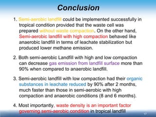
Presentation file on Application on Semi-aerobic Landfill. Technology in in Tropical Climate: Lysimeter experiment of Thailand (Created: SWGA Chart Chiemchaisri)
Call Girl Nagpur Roshni Call 7001035870 Meet With Nagpur Escorts
Semi-Aerobic Landfills Reduce Methane 90% in Tropical Climate
1. Application on Semi-aerobic Landfill Technology in in Tropical Climate: Lysimeter experiment of Thailand
Chart Chiemchaisri, Noppharit Sutthasil, Komsilp Wangyao, Kazuto Endo, Masato Yamada
Department of Environmental Engineering, Faculty of Engineering, Kasetsart University,
Joint Graduate School of Energy and Environment, King Mongkut’s University of Technology Thonburi,
Research Center for Material Cycles and Waste Management, National Institute for Environmental Studies, Japan
2. 2
Anaerobic vs Aerobic landfills
Anaerobic (Conventional) Landfill
The stabilization of most organic waste in landfill took place under absence of oxygen.
High organic strength leachate was generated during acid phase followed by long term stabilization in methane phase.
High CH4 and CO2 in gas produced during methane phase
Semi-aerobic (Fukuoka Method) and Aerobic (forced aeration) Landfill
Introduction of air yielding aerobic degradation in some or whole part of waste body.
Acceleration of waste stabilization and improvement of leachate qualities
Reducing CH4 emission
3. 3
Objective of this research
To investigate the applicability of semi-aerobic landfill technology in tropical climate
How effective can the air diffuse into the waste body under high moisture condition?
To study the effect of initial waste placement (degree of compaction) and leachate retention on waste stabilization, leachate qualities and gas production in semi-aerobic and anaerobic lysimeters.
To determine methane emission ratio between semi- aerobic and anaerobic conditions
Methane Correction Factor (MCF) for semi- aerobic landfill.
4. 4
Methane Correction Factor (MCF) in IPCC Guidelines
MCF indicates degree of anaerobic condition which creates and emits methane gas from solid waste disposal site.
MCF depends on design and operating condition of the landfills. It can also change with time.
IPCC proposed the following default MCF for different types of landfills
Type of Site
Methane Correction Factor (MCF) Default Values
Managed – Anaerobic
1.0
Managed - Semi-Aerobic
0.5
Unmanaged – Deep (>5 m deep)
and/or high water Table
0.4
Unmanaged – Shallow (<5 m deep)
0.8
Uncategorised SWDS
0.6
5. 5
Lysimeters
Sm = Semi-aerobic Landfill condition
An = Anaerobic Landfill condition
Sm I
Sm II
An I
An II
Pan collector of rainwater (70% of lysimeter area)
6. 6
Lysimeters Condition
Sm I
Sm II
An I
An II
Operating Condition
Semi-aerobic
Semi-aerobic
Anaerobic
Anaerobic
Waste compaction
No compaction
Typical compaction
Typical compaction
Typical compaction
Waste density (kg/m3)
600
750
700
700
Leachate drainage
Completed
drainage
Completed
drainage
0.6 m leachate head (normal operation)
Fully submerged condition
8. 8
In-situ monitoring parameters
Temperature Probes
Gas Extraction Tube
Moisture Sensors
Data Logging System
Tedlar Bag
for GC-analysis
9. 9
Sensors installation on the lysimeters
Daily Cover
Lv.4
Lv.3
Lv.2
Lv.1
Initial waste layer height = 2.50 m
Cover soil layer = 0.30 m
10. 10
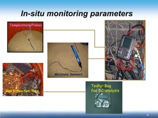
Sampling, Measurement & Analysis
Sample
frequency
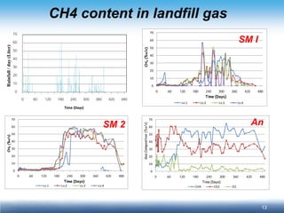
Gas composition (CH4, CO2, O2, N2)
Once a week
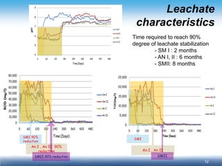
Leachate (pH, EC, BOD, COD, TOC NH4+, TKN, NO3, TP)
Once a week
Gas emission (CH4, CO2)
Once a month
Close Flux Chamber Method
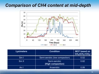
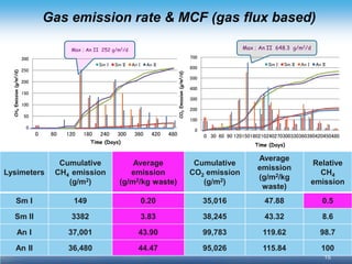
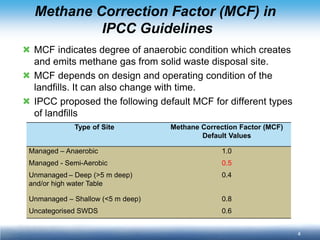
Estimation of MCF based on methane ratio in landfill gas MCF = 1 where %CH4/(%CH4 + %CO2) ≥ 0.6 MCF = [%CH4/(%CH4 + %CO2)]/0.6 where CH4/(%CH4 + %CO2) < 0.6
Gas Emission based on close flux
measurement
F = ρ VΔC/ AΔt
where F = gas flux, g/m2/h
ρ = gas density, g/m3
V = volume of chamber, m3
A = area of chamber, m2
ΔC = gas concentration difference
(volume fraction)
Δt = time, h
11. 11
Variation of rainfall & Settlement
Result
Sm I
Sm II
An I
An II
Settlement (cm.)
Waste Settlement
(% From initial height)
Sm I = 35 cm (14 %)
Sm II = 30 cm (12 %)
An I = 25 cm (10 %)
An II = 15 cm ( 6 %)
Cumulative Rainfall = 1,009 L Amount of leachate (% of rainfall) Sm I = 304 L (30.11%) Sm II = 311 L (30.78%) An I = 301 L (29.82%) An II = 268 L (26.58%)
0
200
400
600
800
1,000
1,200
0
60
120
180
240
300
360
420
480
Cumulative Rainfall / Leachate (L)
rainfall
Sm I
Sm II
An I
An II
Time (Days)
0
10
20
30
40
50
60
70
0
60
120
180
240
300
360
420
480
Time (Days)
Rainfall / day (Liter)
12. 12
Leachate characteristics
05,00010,00015,00020,00025,000060120180240300360420480 TOC(mg/l) Sm ISm IIAn IAn IITime (Days) 010,00020,00030,00040,00050,00060,00070,00080,000060120180240300360420480 BOD (mg/l) Sm ISm IIAn IAn IITime (Days) 456789060120180240300360420480 pH Sm ISm IIAn IAn IITime (Days)
SMI 90% reduction
SMI
An I , An II 90% reduction
An I , An II
SMII 90% reduction
SMII
Time required to reach 90%
degree of leachate stabilization
- SM I : 2 months
- AN I, II : 6 months
- SMII: 8 months
13. 13
CH4 content in landfill gas
010203040506070060120180240300360420480Lv.1Lv.2Lv.3Lv.4 CH4(%v/v) Time (Days)
SM I
0
10
20
30
40
50
60
70
0
60
120
180
240
300
360
420
480
Time (Days)
Rainfall / day (Liter)
010203040506070060120180240300360420480Lv.1Lv.2Lv.3Lv.4 CH4(%v/v) Time (Days) 010203040506070060120180240300360420480CH4CO2O2 Gas Composition(%v/v) Time (Days)
SM 2
An
14. 14
Comparison of CH4 content at mid-depth
010203040506070060120180240300360420480Sm ISm IIAn I (%v/v) Time (Days)
Lysimeters
Condition
MCF based on
CH4/(CH4+CO2)
Sm I
Semi-aerobic (low compaction)
0.52
Sm II
Semi-aerobic
(High compaction)
0.82
An I
Anaerobic
0.99
15. 15
Gas emission rate & MCF (gas flux based)
Lysimeters
Cumulative CH4 emission (g/m2)
Average emission
(g/m2/kg waste)
Cumulative CO2 emission (g/m2)
Average emission
(g/m2/kg waste)
Relative CH4 emission
Sm I
149
0.20
35,016
47.88
0.5
Sm II
3382
3.83
38,245
43.32
8.6
An I
37,001
43.90
99,783
119.62
98.7
An II
36,480
44.47
95,026
115.84
100
Max ; An II 252 g/m2/d
Max ; An II 648.3 g/m2/d
0
50
100
150
200
250
300
0
60
120
180
240
300
360
420
480
Sm I
Sm II
An I
An II
Time (Days)
CH4 Emission (g/m2/d)
0
100
200
300
400
500
600
700
0
30
60
90
120
150
180
210
240
270
300
330
360
390
420
450
480
Sm I
Sm II
An I
An II
Time (Days)
CO2 Emission (g/m2/d)
16. 16
Carbon and Nitrogen balance in the lysimeters
Component
Sm I
Sm II
An I
An II
Residual
41.70
46.47
56.40
36.61
Leachate
0.01
0.02
0.03
0.04
Gas (CH4)
0.05
1.39
16.60
17.27
Gas (CO2)
6.39
5.76
15.02
13.09
Unaccounted
51.84
46.36
11.96
32.99
Carbon
Nitrogen
Component
Sm I
Sm II
An I
An II
Residual
8.30
10.22
14.41
8.90
Leachate
4.67
9.04
10.31
10.82
Gas emission & Unaccounted
87.03
80.74
75.29
80.28
Incl. escape of LFG through leachate pipe (for Sm),
internal deposition after leachate stagnant & evaporation
Microbial transformation & emission in gaseous form
17. 17
Conclusion
1. Semi-aerobic landfill could be implemented successfully in tropical condition provided that the waste cell was prepared without waste compaction. On the other hand, Semi-aerobic landfill with high compaction behaved like anaerobic landfill in terms of leachate stabilization but produced lower methane emission.
2. Both semi-aerobic Landfill with high and low compaction can decrease gas emission from landfill surface more than 90% when compared to anaerobic landfill.
3. Semi-aerobic landfill with low compaction had their organic substances in leachate reduced by 90% after 2 months, much faster than those in semi-aerobic with high compaction and anaerobic conditions (8 and 6 months).
4. Most importantly, waste density is an important factor governing semi-aerobic condition in tropical landfill
18. 18
Future research needs
1. Investigation of optimum aeration rate and operating condition for inducing natural ventilation into semi-aerobic landfill in tropical climate (wet and dry season).
2. Investigation of possibility to introduce bulking materials or using existing specific waste components in semi-aerobic landfill for promotion of natural ventilation.
3. Investigation of nitrous oxide emission rate and its seasonal variation from semi-aerobic landfill operated in tropical climate.
19. This research work is carried out under NIES-KMUTT-KU collaboration research laboratory with financial support from Kasetsart University Research and Development Institute (KURDI)
Acknowledgement