Download as PDF, PPTX
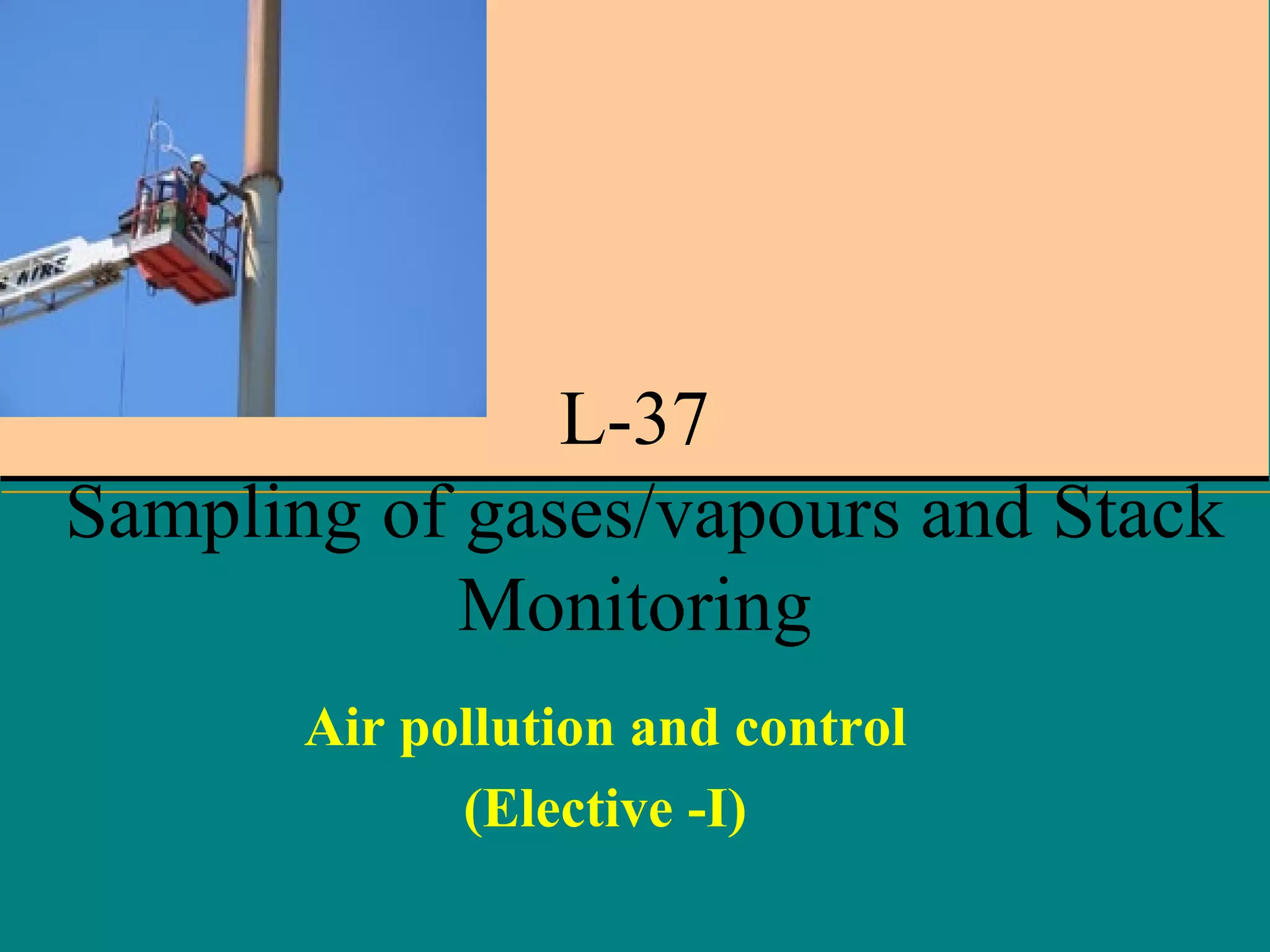
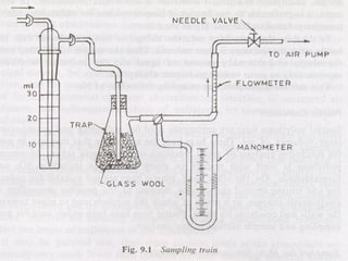
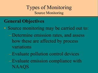
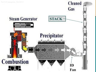
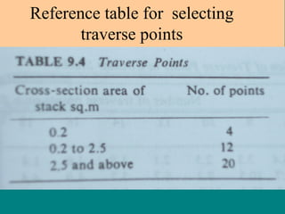
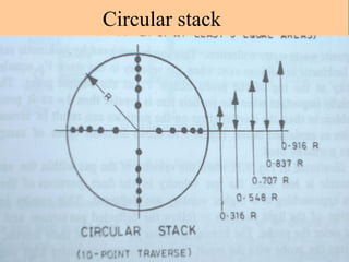
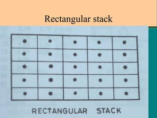
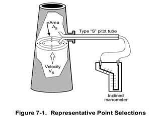
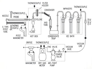
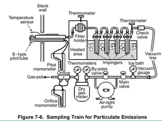
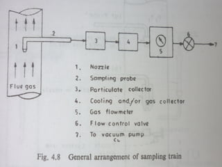
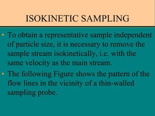

The document outlines various methods and devices used for sampling gases and vapors during air pollution monitoring. It covers principles of isokinetic sampling, types of sampling equipment like probes, suction devices, bags, and adsorption methods, as well as stack monitoring techniques to ensure compliance with environmental regulations. Additionally, it discusses the importance of collecting representative samples from different traverse points in stacks for accurate emissions analysis.