The document discusses the modeling of an anti-surge control system for centrifugal compressors used in natural gas compression stations, detailing the development of a software application for simulation and surge protection mechanisms. It presents a method that includes a flow calculation algorithm and a description of the modeling environment, addressing surge prediction and control strategies while referencing various aspects of compressor operation and dynamics. The findings aim at improving compressor stability and operational efficiency by implementing a flexible and accurate modeling approach compared to traditional methods.
![International Journal of Electrical and Computer Engineering (IJECE)
Vol. 12, No. 2, April 2022, pp. 1419~1428
ISSN: 2088-8708, DOI: 10.11591/ijece.v12i2.pp1419-1428 1419
Journal homepage: http://ijece.iaescore.com
Centrifugal compressor anti-surge control system modelling
Nurlan Batayev1
, Batyrbek Suleimenov1
, Sagira Batayeva2
1
Department of Automation and Control, Satbayev University, Almaty, Kazakhstan
2
Zharsuat General Educational School, West Kazakhstan region, Borili district, Zharsuat, Kazakhstan
Article Info ABSTRACT
Article history:
Received Apr 8, 2021
Revised Aug 25, 2021
Accepted Sep 20, 2021
From the middle of XX century, natural gas is an important mineral, widely
used in the energy sector. Transportation of natural gas is carried out via gas
pipeline networks and compression stations. One of the key features which
need to be implemented for any centrifugal gas compressor is a surge
protection. This article describes the method and develops software
application intended for simulation and study of surge protection system of a
centrifugal compressor used in modern gas compression stations. Within the
article research method, modelling environment’s block diagram, proposed
algorithms and results are described. For surge cases control and prediction,
Anti-surge control block implemented which based on practical experience
and centrifugal compressor theory. To avoid complicated energy balancing
differential equations the volumetric flow calculation algorithm proposed
which is used in combination with Redlich-Kwong equation of state.
Developed software’s adequacy test performed through modeling of one-
stage gas compression scheme at rated speed with comparison of parameters
with reference commercial software and verification of the anti-surge control
system.
Keywords:
Anti-surge control
Centrifugal compressor
Gas compression unit
Polytrophic head
Surge
This is an open access article under the CC BY-SA license.
Corresponding Author:
Nurlan Batayev
Department of Automation and Control, Satbayev University
22 Satbayev Street, 050013, Almaty, Kazakhstan
E-mail: n.batayev@satbayev.university
1. INTRODUCTION
Gas compressors are represented by two common types-dynamic gas compressors and positive
displacement ones. In a positive displacement compressor work is performed by reducing the volume of gas
which increases its pressure. In a dynamic compressor work is done transferring movement kinetic energy to
the gas. By the velocity reduction occurs conversion of kinetic energy into the potential energy or pressure.
Centrifugal and axial compressors are two main types of dynamic compressors. By the series of rotors, the
axial compressors transferring energy of movement to the gas in the axial direction. On the other hand,
centrifugal compressors are performing work by an impeller which transfers movement energy in radial
direction. Then this velocity in a diffuser is converted into pressure.
The instability of a centrifugal gas compressor can appear in two main forms: surging and stalling.
Stalling is a disruption of flow, does not usually damage the centrifugal compressor. In fact, in industrial
environments it can be difficult to identify a stall. The term of compressor surge can be described as audible
thumping and honking at frequencies as low as 1 hertz, severe mechanical vibration, and pressure pulsations
throughout the machine [1]. Surging is an unstable compressor operation mode in which the pressure at the
compressor discharge is large relative to the flow through the compressor. Surging can destroy a compressor,
and most industrial compressors have some form of surge protection. An anti-surge control system protects
compressor from surging, by controlling the suction flow rate of gas to the compressor [2]. Effective](https://image.slidesharecdn.com/36157071509025962emr23nov8aprk-220616062120-7152bad8/85/Centrifugal-compressor-anti-surge-control-system-modelling-1-320.jpg)
![ ISSN: 2088-8708
Int J Elec & Comp Eng, Vol. 12, No. 2, April 2022: 1419-1428
1420
anti-surge control depends on various factors, such as measuring devices accuracy, the type of control valves,
and dynamic response of the process [3]. The surge region is the area to the left of the surge limit line (SLL)
as shown in Figure 1, and it should be given in the compressor performance curves and datasheets.
Figure 1. Operating point position control by anti-surge regulator
The anti-surge control system prevents reaching the “SLL” curve by the operating point “A” as
shown in Figure 1. This is achieving by an additional line of defense called surge control line (SCL) which is
located to the right of “SLL”. Suction gas flow is increasing with the anti-surge valve’s opening, whose
purpose is maintain the operating point in the stable operating area along with the velocity curve.
Speed and anti-surge control circuits are one of the important protection systems for the
compressors. Over the past decades significantly has changed design philosophies for these control systems.
In the mid-seventies, the first analog based electronic control systems appeared on the market. In the eighties
appeared microprocessor systems. In recent years, significant changes have occurred in the market of
microprocessor-based anti-surge systems and speed control systems due to the transition to 32-bit and 64-bit
processors [4], [5]. Different modelling approaches have been proposed in recent years [6]–[15]. Over the
years, to determine more precise operational parameters of the transmission lines, it have been carried out
different numerical simulations of pipeline network systems [16]–[19]. The methods for developing of gas
compression system simulator are described in [20], [21].
As described above, anti-surge regulator maintains the compressor in the stable operating ranges
[22]–[26]. Any regulation basically is based on measurement of flow through the machine and should meet
the basic requirements: i) machine must be protected by the system under all operating conditions, where
included start and stop sequences; ii) surge control line should be as close as possible to a parallel
displacement of the surge limit line considering the safety and efficiency requirements; iii) for the efficient
operation of compressor, surge control line must not get closer to the surge limit line more than it is
necessary.
Surge and high vibration cause emergency shutdown of the gas compressor unit in 20-25% of cases
[27]. The assessment and consequences of surge based on empirical analytical models have been investigated
in various works [28]–[30]. Surge studies and risks, however, need to be studied on a case-by-case basis,
since each gas compressor has its own surge characteristics.
Nowadays there are exists various commercial gas industry simulation programs that can simulate
with high accuracy. Such software packages are very accurate, but they are created through complicated
calculations and material and energy balancing differential equations and may not reflect the entire logic of
the gas compression unit control system in the field. They are widely used to obtain accurate calculations
when simulating various technological processes. But in the tasks of optimal and operational control of the
gas compression unit, the modeling system should be more flexible to the implementation of changes,
depending on the requirements of the technological process, and the speed of calculations is also important.
Most of the simulation programs are based on solving n-order differential equations, which favorably affects
the accuracy of calculations, but at the same time requires more system time than in cases of using simple
algebraic dependencies. Therefore, it is advisable to develop own modeling package that meets these
requirements.
This article provides a description of the anti-surge regulator implemented in the developed gas
compression system simulation software. Implemented anti-surge control strategy used for predicting and
simulating cases of surge and based on practical experience and centrifugal gas compressor theory. Checking
the adequacy of the regulator was done on the basis of the created mathematical model with further](https://image.slidesharecdn.com/36157071509025962emr23nov8aprk-220616062120-7152bad8/85/Centrifugal-compressor-anti-surge-control-system-modelling-2-320.jpg)
![ ISSN: 2088-8708
Int J Elec & Comp Eng, Vol. 12, No. 2, April 2022: 1419-1428
1422
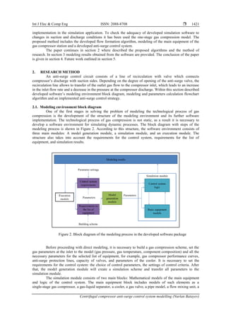
flow separation unit, an anti-surge valve. Models of the main equipment are implemented in the form of
library elements, including the necessary mathematical calculations for gas parameters. The runtime module
is the main engine of the application, whose task is to update the simulation results and transfer them to the
simulation module, considering the requirements for the control system and the simulation scheme.
2.2. One-stage compression system modeling and parameters calculation flowchart
Figure 3 shows the one-stage gas compression stage with anti-surge valve. The circuit contains the
following elements: gas inlet and outlet points, valves, gas flow collection unit, gas flow dividing unit,
centrifugal compressor, recirculation line with anti-surge valve. At every element’s inlet, gas pressure,
temperature, volumetric flow, and gas composition are known parameters. At the input to the system user
through the dialog box must set the initial values of pressure, temperature, and gas composition. The value of
the volumetric gas flow rate is an unknown parameter and need to be calculated every program cycle.
Figure 3. The main components of the one stage gas compression scheme
The volumetric flow rate in the gas compression scheme depends on each of the element’s capacity
(points 𝐺1 − 𝐺6). To find out the volumetric flow rate at the inlet, it is required in the created scheme to
determine the element with the minimum mass flow and divide this mass flow to the gas density at the inlet.
The volumetric gas flow calculation algorithm is described in 7 steps.
Step 1. Searching the minimum capacity of the scheme is starting from the end and move to the beginning of
the circuit. From Figure 3 it can be seen that the last element in the scheme that affects the capacity is “Valve
2”. Therefore, the capacity at point 𝐺1 will be defined as the capacity of “Valve 2”:
𝐺1 = 𝑉𝑙𝑣_2𝑐𝑎𝑝 (1)
where, 𝐺1-gas mass flow rate, [kg/sec]; 𝑉𝑙𝑣_2𝑐𝑎𝑝-the valve’s mass flow rate which depends on size and
properties of the valve.
Step 2. Determination of the recirculation line capacity, which is equal to capacity of the anti-surge valve
(ASV).
𝐺2 = 𝐴𝑆𝑉
𝑐𝑎𝑝 (2)
Step 3. The capacity at the entrance of the branching point (𝐺3) is the sum of the capacities of each of the
outgoing branches:
𝐺3 = 𝐺1 + 𝐺2 (3)
Step 4. Depending on the speed of the centrifugal compressor, it’s capacity also changes. Therefore, the mass
flow at point 𝐺4 is defined as the minimum value of the capacity at point 𝐺3 and the flow through the
centrifugal compressor:
𝐺4 = min( 𝐶𝑜𝑚𝑝𝑟𝑒𝑠𝑠𝑜𝑟𝑐𝑎𝑝, 𝐺3) (4)
Step 5. The capacity at the inlet of the flow mixing unit (point 𝐺5) is determined by subtracting the flow rates
of the remaining inlet branches from the mass flow rate at its outlet:](https://image.slidesharecdn.com/36157071509025962emr23nov8aprk-220616062120-7152bad8/85/Centrifugal-compressor-anti-surge-control-system-modelling-4-320.jpg)
![Int J Elec & Comp Eng ISSN: 2088-8708
Centrifugal compressor anti-surge control system modelling (Nurlan Batayev)
1423
𝐺5 = 𝐺4 − 𝐺2 (5)
Step 6. The flow rate at point 𝐺6 is calculated as the minimum value between the flow rate at point 𝐺5 and
the capacity of “Valve 1”:
𝐺6 = min( 𝑉𝑙𝑣_1𝑐𝑎𝑝, 𝐺5) (6)
Step 7. The volumetric gas flow rate at the inlet of the gas compression scheme is defined as the ratio of the
mass flow rate at point 𝐺6 and the gas density at the inlet:
𝑄𝑖𝑛 =
𝐺6
𝜌𝑖𝑛
(7)
where, 𝑄𝑖𝑛 is the desired value of the volumetric gas flow rate at the inlet to the system, [𝑚3
/sec]; 𝐺6-gas
mass flow rate at point 𝐺6, [kg/sec]; 𝜌𝑖𝑛 is the gas density at the inlet, which is calculated by the standard
equation for density calculation:
𝜌 =
𝑃∙𝑀𝑊
𝑍∙𝑅∙𝑇
(8)
where, P is the pressure, [Pa]; MW is the molecular weight of the gas, [kg/mol]; T is the gas temperature,
[°K]; R-Universal gas constant, [J/(mol ∙ K)]; Z-gas compressibility factor, [-]. The Redlich-Kwong equation
of state (EOS) is used to perform a mass balance and calculation of the compressibility factor Z [31].
2.3. Anti-surge controller development
The surge curves are necessary component of the anti-surge control system and should be given in
the datasheet of the compressor. Figure 4 shows surge curves used in the developed software. The
compressor’s operating point is determined by suction gas flow rate [“Q”] and polytropic Head [“H”]. Below
are described main curves of the anti-surge controller.
Figure 4. Anti-surge regulator curves
Surge limit line-is the curve, where a set of volumetric flow values with the corresponding values of
polytropic pressure determines the limit beyond which the compressor will be in surge and must be presented
in the compressor datasheet. The software application allows to enter this curve through a custom dialog box
window. Surge protection line-is the protection line prior of reaching SLL by operational point. The “SPL”
coordinates are defined as (9).
𝑆𝑃𝐿 = 𝑆𝐿𝐿 ∙ 𝐾𝑆𝑃𝐿 (9)](https://image.slidesharecdn.com/36157071509025962emr23nov8aprk-220616062120-7152bad8/85/Centrifugal-compressor-anti-surge-control-system-modelling-5-320.jpg)
![ ISSN: 2088-8708
Int J Elec & Comp Eng, Vol. 12, No. 2, April 2022: 1419-1428
1424
Where, 𝐾𝑆𝑃𝐿 is the SPL coefficient, by default setpoint is 1.0404 and could be adjusted by user through the
dialog box. If the “SPL” curve is activated in the anti-surge control panel and the operating point of the
compressor reaches “SPL”, after defined delay the compressor protection logic is activated, the logic
immediately opens anti-surge valve to 100% to protect compressor from surge.
Surge correction line-is the line which allows to increase the surge margin and quick opening of
anti-surge valve once the position of the operating point is between “SPL” and “SCrL”. Surge control line-is
the curve along which anti-surge regulator keeps the compressor’s operating point position. If the operating
point for flow rate is less (to the left of the curve) than the “SCntL”, regulator opens the anti-surge valve.
Once the operating point for the flow is larger (to the right of the curve) than “SCntL”, then the regulator will
start closing the anti-surge valve. The “SCntL” position during the normal operation, is defined by (10).
𝑆𝐶𝑛𝑡𝐿 = 𝑆𝐿𝐿 ∙ (1 +
𝑆𝑢𝑟𝑔𝑒 𝑀𝑎𝑟𝑔𝑖𝑛
100
), (10)
Where the value of surge margin could be adjusted by user from the anti-surge control dialog box. In our test
cases we selected surge margin equal to 30%. On real gas compression sites this value could be vary
depending on the specified centrifugal compressor’s anti-surge write-up document.
Anti-surge valve’s position is controlled by a standard proportional-integral-derivative controller
(PID) as it is done on real gas compression sites. The setting of the SP (Set Point) of the controller is defined
by (11).
𝑆𝑃 = 1 +
𝑆𝑢𝑟𝑔𝑒 𝑀𝑎𝑟𝑔𝑖𝑛
100%
(11)
The value of the Process Value (PV) is calculated by the (12).
𝑃𝑉 =
𝑄𝑖𝑛
𝑅𝑂_𝑆𝐸𝑇
(12)
Where, 𝑅𝑂_𝑆𝐸𝑇 is the volumetric flow which corresponds to the polytropic head’s current value, 𝑄𝑖𝑛 is the
gas flow at the compressor suction. The 𝑅𝑂_𝑆𝐸𝑇 parameter defined by linearly interpolating the polytropic
pressure to the “SCntL” curve.
3. RESULTS AND DISCUSSION
The result of the work is developed application for modelling of centrifugal compressor operation
modes with anti-surge control under various dynamic operating conditions. The developed application allows
to create different technological schemes with the elements like valve, gas compressor, cooler, gas-liquid
separator, anti-surge line [32]. The functionality of compressor control system must meet all the requirements
that are necessary to control and regulate the parameters of the main compressor: regulation of pressure of
the compressor on an inlet and discharge sides, flow control, operation of the cooling system, speed control,
control and management of operator alerts, compressor start/stop sequences. Developed software adequacy
test performed through two types of tests: modeling of compressor at rated speed with comparison of
parameters with reference commercial software and verification of the anti-surge control.
3.1. Modelling of compressor control mode at rated speed
In this mode, the compressor operates at steady-state speed without transients. To determine the
adequacy of the model, a comparison was made at compressor nominal speed for developed software and the
reference one (Aspen hysys) with the same compression scheme and properties of the elements. The
centrifugal compressor speed was 3,000 rpm. The comparison was done for seven main parameters at
compressor suction and discharge sides: temperature (T), pressure (P), process gas mass flow rate (𝐹𝑚𝑎𝑠𝑠),
gas density (ρ), process gas volumetric flow rate (𝐹𝑣𝑜𝑙), power (Pow), polytropic head (𝐻𝑝𝑜𝑙𝑦𝑡). The
corresponding results are shown in Table 1.
As it is seen from above table, the difference between the modelling parameters for the developed
software and the reference one is less than 0.6%, which means that proposed methods and algorithms in the
developed software performs adequate calculations. Considering this, developed software could be used for
further anti-surge regulator verification.](https://image.slidesharecdn.com/36157071509025962emr23nov8aprk-220616062120-7152bad8/85/Centrifugal-compressor-anti-surge-control-system-modelling-6-320.jpg)
![Int J Elec & Comp Eng ISSN: 2088-8708
Centrifugal compressor anti-surge control system modelling (Nurlan Batayev)
1425
Table 1. Comparison of compressor suction/discharge modeling parameters at rated speed for developed and
reference software
Developed software Reference software
Parameters Suction Discharge Suction Discharge
T, [C] 22.33 87.68 22.23 85.97
P, [bar] 17.71 37.71 17.61 37.57
𝐹𝑚𝑎𝑠𝑠, [kg/h] 390030 390030 389400 389400
ρ, [kg/m3] 13.93 24.28 13.88 24.39
𝐹𝑣𝑜𝑙, [m3/h] 28005 16064 28050 15970
Pow, [kW] 14113 14113 14045 14045
𝐻𝑝𝑜𝑙𝑦𝑡, [m] 10661 10661 10630 10630
3.2. Anti-surge regulator verification
The simulator interface for anti-surge control is shown in Figure 5. The interface allows to configure
the surge curve, set the parameters of the PID controller, as well as see the parameters of the anti-surge
regulator. As a process of the gas compression, a single-stage scheme with one input and one output was
chosen. According to this scheme, one centrifugal gas compressor with one drive participates in the gas
compression process. This scheme also includes such elements as cooler, gas-liquid separator, valves, pipes.
Anti-surge control line is one of the significant elements of compressor. The system parameters initialization
is an important part. Within this phase is setting inlet gas pressure, temperature, gas composition, valves’
properties, compressor curves (performance curve, efficiency, anti-surge curve), and pipe properties. Correct
operation of the anti-surge regulator is important in the entire process of compressor operation from the
moment of start up to a complete stop. Compressor shutdown is the critical event for the anti-surge regulator
because it should react immediately to prevent the compressor's operating point from entering to the surge
zone.
Figure 5. Anti-surge regulator dialog box
For test purpose it was selected the change in volumetric flow at suction side of the compressor, by
closing the valve at the discharge (“Valve 2” from Figure 3) from 26% to 20% (decrease in flow) and
opening the valve at the discharge from 20% to 26% (increase in flow). During the flow rate decreasing step,
the compressor’s operating point starts moving to the surge area, and regulator initiates anti-surge valve’s
opening, which leads to an increase in flow rate due to transferring part of the volumetric flow to the suction
from the discharge side as shown in Figure 6. Accordingly, when the flow increases, the regulator initiates
anti-surge valve’s closing. As can be seen from the Figure 6, the anti-surge regulator smoothly controls the
operating point without hesitation and aligns its position at the required for safe operation of the compressor
flow rate. The compressor working point tracking during the suction flow change is also shown on Figure 6
(right). As the flow decreased, the working point moves to the left, the reaction of the anti-surge control](https://image.slidesharecdn.com/36157071509025962emr23nov8aprk-220616062120-7152bad8/85/Centrifugal-compressor-anti-surge-control-system-modelling-7-320.jpg)
![ ISSN: 2088-8708
Int J Elec & Comp Eng, Vol. 12, No. 2, April 2022: 1419-1428
1426
regulator is as follows: at the beginning it tries to force the valve’s command rate by moving the SCL to the
right, if this does not help and work point reaches the SPL the regulator opens the anti-surge valve to 100%
for protecting compressors from the surge.
Figure 6. Anti-surge regulator reaction trend to flow change (left) and working point position
tracking (right)
4. CONCLUSION
Within this article is described the software application, designed to simulate gas compression
system’s different operating modes with emphasizing on anti-surge control system and its model. The
research method, modelling environment’s block diagram and proposed algorithms are described. For
prediction and investigate surge cases an anti-surge control block implemented which based on practical
experience and centrifugal compressor theory. To tuning of the main anti-surge regulator parameters (PID
regulator gains, anti-surge curves implementation, and auto/manual control selection) created the appropriate
dialog box.
To determine the adequacy, a comparison was made at compressor nominal speed for developed
software and the reference one with the same compression scheme and properties of the elements. The
difference between the modelling parameters for the developed software and the reference one was less than
0.6%, i.e., the proposed methods and algorithms performs adequate calculations. Anti-surge regulator
verification showed that it is reacts to system disturbance, protects compressor from surge occurrence and
allows to simulate and analyze different cases which is not possible to test on real equipment. To avoid
complicated energy and material balancing differential equations the volumetric flow calculation algorithm
proposed which is used in combination with Redlich-Kwong equation of state. The developed application
practically could be used in centrifugal gas compressor’s operation modes study and analysis.
5. FUTURE WORK
Taking into account that compressor blades contamination leads to high fuel consumption, an
increase in pressure and temperature of the discharge gas, and risks of earlier surge occurrence, the study of
the compressor operating modes by modeling at the boundaries of the permissible operating regions of the
speed and the surge limit line could be used to assess the permissible and critical values of the decrease in
efficiency indicators, as well as the analysis of surge conditions.
ACKNOWLEDGEMENTS
This research has been funded by the Science Committee of the Ministry of Education and Science
of the Republic of Kazakhstan (Grant No. AP08856867).
REFERENCES
[1] H. W. Emmons, C. E. Pearson, and H. P. Grant, “Compressor surge and stall propagation,” Trans. ASME, vol. 77, pp. 455–467,
1955.
[2] K. C. Chui, N. E. Pobanz, and L. H. Chang, “Evaluation of gas turbine/compressor control system effectiveness using dynamic
simulation,” Volume 4: Manufacturing Materials and Metallurgy; Ceramics; Structures and Dynamics; Controls, Diagnostics
and Instrumentation; Process Industries; Technology Resources; General, Sep. 1985, doi: 10.1115/85-IGT-56.](https://image.slidesharecdn.com/36157071509025962emr23nov8aprk-220616062120-7152bad8/85/Centrifugal-compressor-anti-surge-control-system-modelling-8-320.jpg)
![Int J Elec & Comp Eng ISSN: 2088-8708
Centrifugal compressor anti-surge control system modelling (Nurlan Batayev)
1427
[3] J. R. Gaston, “Turbocompressor antisurge control, new solution for an old problem,” Volume 3: Coal, Biomass and Alternative
Fuels; Combustion and Fuels; Oil and Gas Applications; Cycle Innovations, Jun. 1992, doi: 10.1115/92-GT-428.
[4] W. Blotenberg, “An advanced control and monitoring system for turbomachinery,” Volume 5: Manufacturing Materials and
Metallurgy; Ceramics; Structures and Dynamics; Controls, Diagnostics and Instrumentation; Education; IGTI Scholar Award,
Jun. 1995, doi: 10.1115/95-GT-260.
[5] J. R. Gaston, W. B. Piercy, and C. S. Harclerode, “Integrated turbine-compressor controls retrofit for an Olefins unit,” Volume 5:
Manufacturing Materials and Metallurgy; Ceramics; Structures and Dynamics; Controls, Diagnostics and Instrumentation;
Education; IGTI Scholar Award, Jun. 1995, doi: 10.1115/95-GT-349.
[6] S. Othman, M. R. Ab. Ghani, Z. Jano, and T. Sutikno, “Modelling of solar micro gas turbine for parabolic dish based controller
application,” TELKOMNIKA (Telecommunication Computing Electronics and Control), vol. 18, no. 6, pp. 3184–3190, Dec. 2020,
doi: 10.12928/telkomnika.v18i6.16676.
[7] A. A. Vinaya, S. Yulianto, Q. A. M. Okta Arifianti, D. Arifianto, and A. S. Aisjah, “Machinery signal separation using non-
negative matrix factorization with real mixing,” Bulletin of Electrical Engineering and Informatics, vol. 9, no. 4, pp. 1468–1476,
Aug. 2020, doi: 10.11591/eei.v9i4.1956.
[8] A. A. F., A. Ademola, O. H. E., O. O. K., M. Simeon, and A. O. A., “Power quality considerations for embedded generation
integration in Nigeria: A case study of ogba 33 kV injection substation,” International Journal of Electrical and Computer
Engineering (IJECE), vol. 11, no. 2, pp. 956–965, Apr. 2021, doi: 10.11591/ijece.v11i2.pp956-965.
[9] J. M. Ahmed, “Optimal tuning linear quadratic regulator for gas turbine by genetic algorithm using integral time absolute error,”
International Journal of Electrical and Computer Engineering (IJECE), vol. 10, no. 2, pp. 1367–1375, Apr. 2020, doi:
10.11591/ijece.v10i2.pp1367-1375.
[10] N. A. Sulaiman, M. P. Abdullah, H. Abdullah, M. N. S. Zainudin, and A. Md Yusop, “Fault detection for air conditioning system
using machine learning,” IAES International Journal of Artificial Intelligence (IJ-AI), vol. 9, no. 1, pp. 109–116, Mar. 2020, doi:
10.11591/ijai.v9.i1.pp109-116.
[11] N. Batayev, “Axial compressor fouling detection for gas turbine driven gas compression unit,” Indonesian Journal of Electrical
Engineering and Computer Science, vol. 15, no. 3, pp. 1257–1263, Sep. 2019, doi: 10.11591/ijeecs.v15.i3.pp1257-1263.
[12] D. Adolfo, N. Batayev, C. Carcasci, and T. Shuvatov, “Dynamic simulation of a gas compressor station,” in AIP Conference
Proceedings 2191, 2019, Art. no. 020002, doi: 10.1063/1.5138735.
[13] A. V Thomas Jayachandran, A. Y. Tkachenko, H. H. Omar, and A. Krishnakumar, “Modeling and parametric optimization for a
solar-powered closed-cycle micro gas turbine for space applications,” Journal of Physics: Conference Series, vol. 1745, no. 1,
Art. no. 012099, Feb. 2021, doi: 10.1088/1742-6596/1745/1/012099.
[14] H. M. Harrison and N. L. Key, “A new approach to modeling slip and work input for centrifugal compressors,” Journal of
Engineering for Gas Turbines and Power, vol. 143, no. 2, Feb. 2021, doi: 10.1115/1.4049412.
[15] A. A. Drozdov, Y. B. Galerkin, O. A. Solovyeva, K. V Soldatova, and A. A. Ucehovscy, “Development and identification of a
mathematical model of centrifugal compressor stages using the universal modeling method,” in AIP Conference Proceedings
2285, 2020, Art. no. 030057, doi: 10.1063/5.0026727.
[16] C. Borraz-Sánchez and R. Z. Ríos-Mercado, “A hybrid meta-heuristic approach for natural gas pipeline network optimization,” in
Lecture Notes in Computer Science, Springer Berlin Heidelberg, pp. 54–65, 2005.
[17] A. Sedliak and T. Žáčik, “Optimization of the gas transport in pipeline systems,” Tatra Mountains Mathematical Publications,
vol. 66, no. 1, pp. 103–120, Jun. 2016, doi: 10.1515/tmmp-2016-0024.
[18] P. J. Wong and R. E. Larson, “Optimization of tree-structured natural-gas transmission networks,” Journal of Mathematical
Analysis and Applications, vol. 24, no. 3, pp. 613–626, Dec. 1968, doi: 10.1016/0022-247X(68)90014-0.
[19] D. De Wolf and Y. Smeers, “The gas transmission problem solved by an extension of the simplex algorithm,” Management
Science, vol. 46, no. 11, pp. 1454–1465, Nov. 2000, doi: 10.1287/mnsc.46.11.1454.12087.
[20] K. K. Botros, P. J. Campbell, and D. B. Mah, “Dynamic simulation of compressor station operation including centrifugal
compressor and gas turbine,” Journal of Engineering for Gas Turbines and Power, vol. 113, no. 2, pp. 300–311, Apr. 1991, doi:
10.1115/1.2906563.
[21] R. A. Stanley and W. R. Bohannan, “Dynamic simulation of centrifugal compressor systems,” in Proceedings of the Sixth
Turbomachinery Symposium, pp. 123–132, 1977.
[22] R. Izmaylov and A. Lebedev, “Centrifugal compressor surge detecting method based on wavelet analysis of unsteady pressure
fluctuations in typical stages,” IOP Conference Series: Materials Science and Engineering, vol. 90, Art. no. 012052, Aug. 2015,
doi: 10.1088/1757-899X/90/1/012052.
[23] A. Lebedev, L. Gileva, A. Danilishin, and M. Sokolov, “Surge protection system development in centrifugal compressor with an
indicative method using numerical simulation of unsteady processes and analysis of pressure fluctuation signals,” MATEC Web of
Conferences, vol. 245, Art. no. 09010, Dec. 2018, doi: 10.1051/matecconf/201824509010.
[24] N. Batayev and A. Onbayev, “Prediction of gas turbine parameters based on machine learning regression methods,” in The 6th
International Virtual Conference on Advanced Scientific Results, Jul. 2018, pp. 217–221, doi: 10.18638/scieconf.2018.6.1.495.
[25] M. L. Hakim, B. Achmad, and J. P. Sutikno, “Anti surge control of centrifugal compressor at PT. Pertamina EP asset 2 field
pendopo,” E3S Web of Conferences, vol. 42, Art. no. 01010, Jun. 2018, doi: 10.1051/e3sconf/20184201010.
[26] N. Batayev, “Forecasting and diagnostic of gas turbine driven gas compression unit parameters,” in Materials of the IV
International Scientific-Practical Conference, pp. 186–191, 2019.
[27] A. Hafaifa, B. Rachid, and G. Mouloud, “Modelling of surge phenomena in a centrifugal compressor: Experimental analysis for
control,” Systems Science and Control Engineering, vol. 2, no. 1, pp. 632–641, Dec. 2014, doi: 10.1080/21642583.2014.956269.
[28] P. K. Veldandi, V. R. Kumar, and C. Sailu, “Anti surge control design for variable speed compressor using dynamic simulation,”
International Journal of Applied Engineering Research, vol. 12, no. 1, pp. 636–640, 2017.
[29] C. J. Backi, J. T. Gravdahl, and S. Skogestad, “Robust control of a two-state Greitzer compressor model by state-feedback
linearization,” in 2016 IEEE Conference on Control Applications (CCA), Sep. 2016, pp. 1226–1231, doi:
10.1109/CCA.2016.7587974.
[30] M. A. Asadzadeh and F. Shabani, “Centrifugal compressor active surge controller design based on fuzzy type II,” in 2018 IEEE
Texas Power and Energy Conference (TPEC), Feb. 2018, pp. 1–6, doi: 10.1109/TPEC.2018.8312079.
[31] O. Redlich and J. N. S. Kwong, “On the Thermodynamics of solutions V. An equation of state fugacities of gaseous solutions,”
Chemical Reviews, vol. 44, no. 1, pp. 233–244, Feb. 1949, doi: 10.1021/cr60137a013.
[32] N. Batayev, T. Shuvatov, A. Kuzyrgaliyev, and R. Krikbayev, “Modeling and research of gas transportation unit operation
modes,” International Review of Mechanical Engineering (IREME), vol. 13, no. 4, Art. no. 224, Apr. 2019, doi:
10.15866/ireme.v13i4.17161.](https://image.slidesharecdn.com/36157071509025962emr23nov8aprk-220616062120-7152bad8/85/Centrifugal-compressor-anti-surge-control-system-modelling-9-320.jpg)