1) The document evaluates different anti-surge control concepts for preventing surge and overheating in a compressor system during an emergency shutdown (ESD) using dynamic process simulation.
2) Simulation results show that implementing a hot bypass or cold bypass valve, in addition to the standard anti-surge control valve, can effectively prevent surge during an ESD event if the bypass valve has sufficient capacity. The hot and cold bypass concepts performed similarly in preventing surge.
3) It is recommended to implement the cold bypass concept to avoid overheating, though heating is only slightly less than with the hot bypass. This recommendation is based on analysis of a single predefined ESD case.
Advanced Anti surge Control System for Turbine Driven Centrifugal CompressorsArslan Ahmed Amin
Advanced Anti surge Control System for Turbine Driven Centrifugal Compressors
Please subscribe to my YouTube Channel for best training lectures:
https://www.youtube.com/channel/UCRkUJFOsyZG1E1LDWzUr_hw/playlists?view_as=subscriber
Wrong Sizing of a Reciprocating CompressorLuis Infante
Performance mapping has become a key analytical tool for the diagnostic and optimization of recip compressors, together with electronic performance analyzers. This analysis case illustrates how difficult is to operate a thermodynamically unbalanced multistage integral compressor in a borderline application. An in-house plotting routine in MS Excel (R) was used to map the basic performance (power and flow) of the individual stages across the operating range, and also to produce special-purpose maps in order to graphically depict other mechanical limits, thus helping the field operators to find (and avoid) the root cause of major troubles, including a catastrophic crankshaft failure. Mitigation and remedial cases are explored.
Pneumatic control valve
Actual Pneumatic Control Valve
Typical Actuator & Valve
introduction to actuator
Actuator power
Actuator Fluids
Diaphragm Actuator
Positioner Indicator
Valve Body
Valve Plugs
Reverse & Direct Actuators
Air-To-Open vs. Air-To-Close
control valve
Controller Tuning
Selection of controller modes
Tuning Rules
Ziegler – Nichols Controller Settings
Air compressor overview and basic selection guideAnilkumar B Nair
Provide an overview of Air compressors
Provide a generic guideline for Air compressor selection process
This presentation is prepared for target audience:Facility Managers, Utility Engineers. Technicians and Process associates
Cfd simulation of single stage axial flow compressor for varying blade aspect...eSAT Journals
Abstract The aspect ratio of blade is an important parameter and has a strong influence on the performance of axial flow compressor. The performance of axial flow compressors is known to be affected by the choice of aspect ratio (the ratio of blade height to axial chord length). A study has been carried out to verify the effect of aspect ratio on the performance of 1.2 pressure ratio single stage subsonic compressor through AxStream analysis using Axial flow compressor design. The analysis has been carried out for the constant tip diameter of the compressor rotor blade having an aspect ratio 1, 2 and 3 and obtained the pressure loss and flow parameters of the compressor stage. This paper shows that the best operating conditions occur for the aspect ratio between 2 and 3. Keywords: Axial flow compressor, Aspect ratio, Computational Fluid Dynamic, AxStream
Design optimization of an axial flow compressor for industrial gas turbineeSAT Publishing House
IJRET : International Journal of Research in Engineering and Technology is an international peer reviewed, online journal published by eSAT Publishing House for the enhancement of research in various disciplines of Engineering and Technology. The aim and scope of the journal is to provide an academic medium and an important reference for the advancement and dissemination of research results that support high-level learning, teaching and research in the fields of Engineering and Technology. We bring together Scientists, Academician, Field Engineers, Scholars and Students of related fields of Engineering and Technology
It is an introduction to fluid power systems and describes the same with an anlogy to the human body.It also contains a comaprison with other systems with advantages and drawbacks
In the hydrocarbon processing and production industry, gas is compressed for transportation to consuming markets and for use in processing operations. This presentation is about the construction and operation of compressors.
In this presentation you will learn about the construction and operation of centrifugal compressors.
Surge is often overlooked in hydraulic system design, but it is influenced by pumps, controls, valves, piping, and more. It is a mistake to overlook the huge impact of both surge and its close cousin, slam.
My presentation at Society of Petroleum Engineers (Western Australia) on 20/10/2015.
In this presentation, I have discussed how a gas pipeline facility can be designed to save 70% on fuel gas consumption.
Le GNL VITOGAZ est :
- Un produit à proximité des sites d’extraction.
- transporté par navire méthanier: taille moyenne 140.000 m3
- importé et stocké à pression ambiante dans des terminaux avant d’y être re-gazéifié (et appauvri) vers le réseau de transport de Gaz Naturel (GRTgaz en France)
PE999.Compressors and Pumps: Selection, Applications, Operation, Troubleshoot...petroEDGE
Maximum efficiency, reliability, and longevity of compressors, pumps, and bearings are of great concern to many industries. These objectives can only be achieved by understanding the characteristics, selection criteria, sizing calculations, sealing arrangements, common problems, repair techniques, as well as their preventive and predictive maintenance. This course is a MUST for those who use this equipment. It covers how compressors and pumps operate and provides the guidelines and rules that must be followed for their successful application. Their basic design, specification and selection criteria, sizing calculations as well as all maintenance issues including vibration analysis, and used oil analysis are discussed in detail.
Objectives
• To provide an understanding of the various types of compressors, pumps, and bearings so participants can operate, maintain and troubleshoot compressors and pumps for their applications.
• To achieve reduced capital, operating and maintenance costs along with increase in efficiency.
Upon participating in this course, delegates will be able to:
• Carry out troubleshooting of critical components with the knowledge of common failure modes of compressors and pumps by applying advanced fault detection techniques.
• Identify bearings and lubrication, pump and compressor sealing arrangements, meet commissioning requirements, conduct vibration measurement and used oil analysis.
• Determine the maintenance required to minimize compressor and downtime, pump operating cost and maximize their efficiency, reliability, and useful life.
• Gain an understanding of compressor surge and surge prevention systems.
• Understand the causes of failures in compressors and pumps.
• Determine all the features that improve the efficiency and reliability of compressors and pumps.
• Identify different types of compressor and pumping systems.
• Gain an understanding of the various types of sealing arrangements used in compressors and pumps.
The Process Safety Management (PSM) Standard requires that covered facilities manage change through a Management of Change (MOC) program. A robust MOC program effectively identifies and analyzes changes. Observation has shown that many MOC processes have deficiencies in training[1], whereas the Authors have observed that other facilities with effective MOC processes employ checklists and workflows to help MOC facilitators identify when engineering expertise is needed (e.g. Preventative Maintenance updates or changes in engineering documents / Process Safety Information (PSI)). It is important to note that PSI encompasses an array of information, which in addition to process safety, is also utilized to make decisions associated with asset expansions and optimization. Updating relief systems PSI is an essential, and often overlooked, aspect of MOC. When changes affecting relief systems are not recognized, a facility will often have to undertake the costly and untimely process of periodically restudying and revising the relief system PSI. These periodic studies can lead to unexpected asset installations and/or operating parameter changes. Based on experiences at various facilities, a workflow is presented in this paper as a timely method for plant level engineers to recognize changes that can affect relief systems. Ultimately this methodology can reduce the error rate associated with MOC and ensure related relief system PSI is accurately updated.
In chemical processing industry the pressure inside the vessel is increase due to many reasons. An
important responsibility of a chemical plant designer is to make sure that a plant under design, can be operated
safely, it is provided with primary, secondary safety arrangement. One of the dangerous situations that can be
arises during operation inability of a system to a pressure higher than that for which it was designed. With
designing pressure safety release valve for inside vessel pressure, should be giving priority to mechanical systems
to release inside pressure. The reasons are many for increase/exceed inside pressure. Most flow applications
require regulating the flow of liquid, and usually the parameter of concern is the pressure. This paper focuses on
the review on design of self regulating pressure valve by using transient finite element analysis. There are many
authors work on this pressure valve. This paper includes study of various papers related to self regulating pressure
valve. In this project focus on exchange of liquid between two chambers, where in it is required that flow be shut
off when a certain pressure is reached .Electronic valves are available, however the intent of this design project is
have a total mechanical system, which has an in built response mechanism.
Centrifugal compressor anti-surge control system modellingIJECEIAES
From the middle of XX century, natural gas is an important mineral, widely used in the energy sector. Transportation of natural gas is carried out via gas pipeline networks and compression stations. One of the key features which need to be implemented for any centrifugal gas compressor is a surge protection. This article describes the method and develops software application intended for simulation and study of surge protection system of a centrifugal compressor used in modern gas compression stations. Within the article research method, modelling environment’s block diagram, proposed algorithms and results are described. For surge cases control and prediction, Anti-surge control block implemented which based on practical experience and centrifugal compressor theory. To avoid complicated energy balancing differential equations the volumetric flow calculation algorithm proposed which is used in combination with Redlich-Kwong equation of state. Developed software’s adequacy test performed through modeling of onestage gas compression scheme at rated speed with comparison of parameters with reference commercial software and verification of the anti-surge control system.
Natural gas operations considerations on process transients design and controlISA Interchange
This manuscript highlights tangible benefits deriving from the dynamic simulation and control of operational transients of natural gas processing plants. Relevant improvements in safety, controllability, operability, and flexibility are obtained not only within the traditional applications, i.e. plant start-up and shutdown, but also in certain fields apparently time-independent such as the feasibility studies of gas processing plant layout and the process design of processes. Specifically, this paper enhances the myopic steady-state approach and its main shortcomings with respect to the more detailed studies that take into consideration the non-steady state behaviors. A portion of a gas processing facility is considered as case study. Process transients, design, and control solutions apparently more appealing from a steady-state approach are compared to the corresponding dynamic simulation solutions.
Study on a linear relationship between limited pressure difference and coil c...ISA Interchange
On/off solenoid valves with PWM control are widely used in all types of vehicle electro-hydraulic control systems respecting to their desirable properties of reliable, low cost and fast acting. However, it can hardly achieve a linear hydraulic modulation by using on/off valves mainly due to the nonlinear behaviors of valve dynamics and fluid, which affects the control accuracy significantly. In this paper, a linear relationship between limited pressure difference and coil current of an on/off valve in its critical closed state is proposed and illustrated, which has a great potential to be applied to improve hydraulic control performance. The hydraulic braking system of case study is modeled. The linear correspondence between limited pressure difference and coil current of the inlet valve is simulated and further verified experimentally. Based on validated simulation models, the impacts of key parameters are researched. The limited pressure difference affected by environmental temperatures is experimentally studied, and the amended linear relation is given according to the test data.
• Surge analysis and dynamic simulation of pumped pipeline systems and networks.
• Preparing conceptual hydraulic designs, to advise on optimum pipeline routing and sizing, equipment selection and operating philosophy.
• Pump selection and optimisation of wet well volumes, with switching levels, to minimise the number of pumping cycles and reduce energy costs.
• Air valve selection and calculation of pipe diameters with gradients that will ensure stable flow development in drained sections of descending pipelines.
• Commissioning support and trouble-shooting on-site, with transient flow and pressure measurement/recording.
• Feasibility, capital and running cost estimates of pumping and pipeline systems
♦ Flow Assurance Studies
♦ Multiphase Flow Modeling
♦ Pipeline Efficiency Studies
♦ Surge Analysis Studies
♦ Thermal Analysis Studies
♦ Pipeline Leak Detection and Feasibility Studies
Pulsation and Vibration Study Of Reciprocating Compressor According To API 6...IJMER
The compressor package contains the reciprocating compressor, pulsation dampers, gas coolers and the connected pipe system which are often the heart of an installation and should be operate smoothly and reliably. The compressor piping vibrations can contribute to fatigue failure of the system or entire package which can lead to unsafe situations for human being as well as environment,
loss of capacity and increase in maintenance as well as repair cost and to avoid this situation compressor piping vibration analysis to be carried out at a very early stage of the design of an installation. The pulsation analysis should be carried out before the piping vibration analysis. The
guidelines for the pulsation analysis are given in API 618 Approach 2 and the guidelines for the vibration analysis are given in API 618 Approach 3. The original system layout is checked with respect to pulsations with all operating cases that are characterized by steady-state operating conditions. The different gas properties and operation cases are considered with valve unloading cases as operation
cases. The measures are proposed to reduce pressure pulsation by installation of orifices. The shaking
forces are used in the subsequent vibration study. After the analysis of pulsation results, find out the worst case for the vibration study means we used the shaking forces induced by pressure pulsation excite the mechanical piping system of worst case. The Vibration Study determines the effect on the mechanical piping system and proposes measures to avoid stresses possibly leading to deformation or rupture by fatigue. The finite element program ANSYS is used for modeling of the mechanical system. The model is built of several types of basic piping elements (e.g. pipes, beams, elbows, T-pieces) connected at node points. The odifications are proposed to meet agreed criteria of vibration. This paper demonstrated that by properly analysising the compressor piping vibration in an accurate and economic way using Pulsim and Ansys software. The accuracy of the analytical solution is validated by
means of experimental results by using B & K Analyser for the measurement of compressor piping vibration.
Design of Industrial Electro-Hydraulic Valves, New ApproachIJERA Editor
A fully flexible valve actuation systems are being under consideration as an enabling technology for advanced internal combustion engine concepts. Electro-hydraulic valve actuator systems are being considered as a dominating variable valve technology. Compared to the servo control system, the system using a proportional valve has the advantages of low price, high anti-pollution ability and high reliability. Unlike existing electromechanical or servo actuated electro-hydraulic valve actuation systems, precise valve motion control is achieved with an internal feedback mechanism. This feedback mechanism can be turned on or off in real-time using simple two state valves which helps reduce the system cost and enables mass production.
For the pipe stress analysis of any piping system, different kinds of loads need to be considered. Let us take a look at different kind of loads that are required to be considered for stress analysis of any piping system.
Parametric study of a low cost pneumatic system controlled by onoff solenoid ...eSAT Journals
Abstract Expensive proportional valves are dominantly used in pneumatic positioning systems even with low demanding accuracy
positioning tasks, which deprive pneumatic systems from its economical advantages. Thereby, using low cost on/off solenoid
valves instead of proportional valves has been a topic of research in the last decades. In this paper, a parametric study is
conducted to investigate the effect of using low-cost 3/2 internally pilot on/off solenoid valves to control a double acting cylinder
and study the system nonlinear response to on/off and PWM input signal. Matlab ® Simscape library is used to model and
simulate the system. The model is validated though experimental measurements of the system behavior. The model is used to study
and decrease the nonlinear pressure response associated with the cylinder chambers in addition to the evaluation of the dead
zone and operating range of the on/off solenoid valve when operated with PWM signal. The results show that using a meter-in
flow control and having a near constant cylinder back pressure can reduce the nonlinearity. An orifice of 1e-6 m2 can reduce the
pressure variation by 80% but increase the transient time. Connecting an accumulator with 1 liter volume can result in 50%
reduction in rod side pressure variation. The model has been used to predict the PWM parameters as well. It has been found that
the most suitable parameters for this valve are 20 Hz and duty cycle from 12 to 65%. These results encourage going further with
controlling a pneumatic position system using low-cost control valves and a simple controller.
Keywords: Pneumatic Control, PWM, On/Off Valves, Simscape, Matlab
1. Evaluation of Anti-Surge Control Concepts during ESD
Simulation of dynamic process behaviour with PULSIM
ir. O.van Wolfswinkel
ir. J.P.M. Smeulers
Abstract
This paper describes the potential of dynamic process simulation for operators and engineering
contractors as a tool to analyse and solve operational and (front-end) engineering issues. The possibilities
are illustrated by a typical project involving system dynamics. The objective of this project was to
evaluate the effectiveness of several alternatives to prevent surge and overheating in a compressor system
during emergency shutdown (ESD).
1. Simulation of Process Dynamics
1.1 Introduction
Safety, availability, operability and product specification are key performance indicators for operators of
industrial processes and pipeline installations and the engineering contractors who design these facilities.
Increasingly, operational criteria related to plant performance are assessed at dynamic operating
conditions by simulation (e.g. Lamey, 1999).
Simulation plays an important role in the analysis of process dynamics both during transient operations
(e.g. start-up, shutdown, trip and change of feedstock) and at steady-state operating conditions (e.g.
regarding stability and controllability). The TNO Flow and Structural Dynamics department has
performed integrated dynamic response analyses for oil & gas production facilities, (petro)-chemical
plants and metallurgical installations. These so-called system dynamics studies (SDS) have been used in
(conceptual) engineering, commissioning and troubleshooting projects.
The TNO Flow and Structural Dynamics department has assisted clients in the oil & gas and
petrochemical industries for more than 30 years to prevent and solve problems regarding the dynamic
behaviour of flow in process installations. Historically these services have been directed to a large extent
at installations containing reciprocating compressors. Pulsation and mechanical response analyses are
executed according to API standard 618 to identify potential pulsation and vibration problems and to
recommend corrective measures. The pulsation studies are performed using PULSIM (Egas, 2001), a
TNO proprietary simulation tool developed to solve industrial problems regarding the dynamic behaviour
of flow in complex pipe systems, process installations and fluid machinery. Typical examples of the
operational issues that can be analysed using PULSIM are:
• Analysis of flow-induced pulsations (FIPs) in Gas Metering and Control Stations (Peters, 2001)
• Pulsation analysis of installations containing positive displacement machinery
• Pulsation analysis of Hyper-compressors (Bokhorst, 2001)
• Stability analysis of centrifugal compressor systems
The frequency range of interest in case of pulsation studies lies roughly between 1 Hz and 500 Hz.
Pulsation studies mainly focus at the process dynamics around a specific steady-state operating point. The
operating range of interest is delimited for pressure by a margin of roughly plus or minus 10% of the
operating point. The temperature profile along the system can be considered constant in time. Variations
of fluid compositions are handled by simulating distinct duties. The method of characteristics is used to
solve the model equations with sufficient accuracy in this operating envelope to meet the project
objectives. Uncertainties in the model and process conditions are handled by a sensitivity analysis.
2. 1.2 SDS Simulation Tool
For some years now, a growing number of system dynamics studies has been performed successfully to
investigate various issues in (front-end) engineering, commissioning and troubleshooting, such as:
• System layout and equipment selection.
• Process control (e.g. evaluation of controllability, stability and capacity control).
• Plant availability.
• Dynamic operating procedures (such as emergency blow down, start-up, shutdown or variation of
feed gas composition).
• Analysis of a trip response and review of safeguarding actions as included in the cause and effect
diagrams (e.g. response of a HIPPS system).
• The effect of failure on demand of (instrumented) safeguarding functions during emergency
situations. Failure modes could relate for instance to ESD valves, depressurisation valves or
instrument malfunction.
• The effect of revealed failures such as a spurious trip of a single piece of rotating or static
equipment, a valve or instrument.
In order to deliver this new range of services to our customers, a special simulation tool called PULSDS
is developed within the PULSIM simulation environment. PULSDS uses an integrated approach to
predict dynamic process behaviour and includes the following physics and elements.
• Heat transfer between the fluid flow, the pipe wall and the environment
• Compositional tracking of the fluid components
• Process controllers
• Models of fluid machinery and fired equipment
Driven by the needs recognised in the market, the capabilities of PULSDS are continuously being
expanded and improved.
Generally speaking, the relevant variations of the process conditions are relatively slow compared to a
pulsation study and occur at a frequency range from 0.001 to about 10 Hz. The dynamic operating range
of interest is relatively large. Pressure and flow vary in a range of 0 to 200% of the nominal operating
condition. The temperature and compositional profiles are calculated continuously. A solution method for
SDS studies is currently developed in order to meet these new demands.
2. Evaluation of Anti-Surge Control Concepts during ESD
2.1 Background and Summary
The project presented here illustrates a typical system dynamics study (SDS). The SDS concerns the
performance of a compressor system in a gas conditioning plant. The experience of the operator with
existing gas compressors shows that the performance of the basic anti-surge control (ASC) system can be
insufficient to prevent surge during emergency shutdown (ESD) events. In order to improve the response
of the ASC system in emergency situations, implementation of a so-called hot bypass or a cold bypass
can be considered. The TNO Flow and Structural Dynamics department has performed a dynamic
response analysis with PULSIM to evaluate the effectiveness of these concepts to prevent surge and
overheating of the compressor during ESD.
The compressor system that has been analysed can be described as follows. A fixed speed booster
compressor is used to pressurise lean gas supplied by a turbo-expander/recompressor. The gas is
subsequently cooled and delivered to the suction manifold of existing pipeline compressors. Both
compressors are equipped with regular ASC recycle lines and pressure equalising lines. Depressurisation
lines are located at the discharge side of both compressors. A schematic overview of the process that has
been modelled and analysed, including all relevant valves, is presented in figure 2.1.
3. %RRVWHU
&RPSUHVVRU
5HFRPSUHVVRU
$LURROHU
+RW%SDVV
ROG%SDVV
)ODUH+HDGHU
)ODUH+HDGHU
PCV
1
BV
2
PCV
3
BV
3
EBVPCV
2
2Q2II9DOYH
RQWURO9DOYH
KHFN9DOYH
ASCV
2
HBPV
CBPVEQV
2
EDV
EQV
1
ASCV
1
BV
1
('9
(49
39
(%9
%9
$69
+%39
%39
(PHUJHQF'HSUHVVXULVDWLRQ9DOYH
3UHVVXUH(TXDOLVDWLRQ9DOYH
3UHVVXUHRQWURO9DOYH
(PHUJHQF%ORFN9DOYH
%ORFN9DOYH
$QWL6XUJHRQWURO9DOYH
+RW%SDVV9DOYH
ROG%SDVV9DOYH
Figure 2.1 – Schematic overview of booster compressor system as simulated with PULSIM.
The hot bypass was perceived to be the preferred concept to prevent surge due to the proximity to the
compressor. To prevent overheating, the compressor vendor recommended limiting the capacity of the hot
bypass valve to 50% of the ASC valve capacity. The capacity of the cold bypass valve was recommended
to be equal or twice the ASC valve capacity. Dynamic simulation helped to quantify the effect of these
recommendations. Alternatively, simulation can be used as a design tool to specify cost-effective valve
sizes, characteristics and required opening times.
Analysis of the dynamic system response showed that implementation of the hot bypass and/or the cold
bypass can be effective to avoid surge during ESD. The improvement of the response is only marginally
better for the hot bypass concept (when comparing identical valves). The temperature response both for
the hot bypass and the cold bypass remained well within specifications, even when a hot bypass valve
capacity of 100% of the ASC valve was selected.
3.2 Description of the Hot/Cold Bypass Concept
Prevention of Surge
The ASC system uses recycling of the compressed medium to reduce the differential pressure over the
compressor and to increase compressor throughput. However, operator experience shows that surge may
still occur during ESD, when the ASC system uses a control valve only. A compressor manufacturer
stated that this problem can be aggravated by a large compressor discharge volume, which is the case
4. when air-cooled after coolers are used. For this reason the hot bypass and the cold bypass concepts have
been developed to prevent surge when a fast response is required in emergency situations (see figure 2.1).
The hot bypass is in fact a recycle line located very close to the compressor. The gas that is recycled via
this line has not been cooled. The cold bypass is a line parallel to the regular ASC valve, thereby retaining
the after cooler in the recycle loop. Both the hot and the cold bypass contain on/off valves with a quick
opening characteristic. The ‘stem travel’ speed of these valves is about twice as fast as the ASC valve.
The central idea of both concepts is:
1. To increase the speed of response of the recycle flow. A faster response is realised by
implementing valve-actuator combinations, which open much faster than a regular anti-surge
control valve. This can be achieved by reducing ‘stem travel time’ and by selecting a quick
opening valve characteristic instead of the linear characteristic that is used for the ASC valve.
2. To increase the recycling capacity during emergency situations. The extra valve will increase the
total recycling capacity during emergency shutdown, which will help to reduce the pressure
difference across the compressor at a faster rate.
3. A third way to increase the speed of response of the ASC system in case of emergencies is to
limit the effective volume of the compressor suction and/or discharge side. This may be realised
under certain conditions by the implementation of a (non-slam) check valve downstream of the
hot bypass at the compressor discharge side. This set-up will only be effective when the capacity
of the hot bypass exceeds compressor throughput.
Prevention of Overheating
Recycling will lead to heating whenever the compressed gas cannot be cooled to the initial operating
temperature at the compressor suction side. This is the case both for the hot bypass and cold bypass
concept. Overheating is defined as the occurrence of temperatures within the compressor exceeding
180 °C. The actual temperature response at the inlet of the Booster Compressor during an ESD event will
depend on a variety of factors, such as:
• The amount of gas recycled via the hot/cold bypass and the regular anti-surge valve
• The decay rate of the speed of the relevant compressors
• The response of the after cooler (air fans)
• The speed of response of all valves actuated upon ESD, with respect to flow.
3.3 Problem Description and Objective
In order to perform a system dynamics study, the objective has to be clearly specified in operational
terms. The objective could for instance relate to safety, availability or operability. Consequently, the
relevant part of the process, including control and safeguarding functions, should be determined and
modelled in sufficient detail. The operating cases should be defined in terms of the state variables of the
process, equipment, actuators and controllers. Uncertainties (e.g. valve opening times) have to be
identified and should be addressed in a sensitivity analysis.
Objective
The main objective of the analysis is to evaluate the effectiveness of both the hot and cold bypass concept
to prevent surge and overheating of the compressor, during a pre-defined ESD event.
Operating Case and Initialisation
The dynamic response of the system is determined starting at a steady-state operating condition. Specific
cases have been selected based on data provided by the EPC contractor. The model has been tuned to
reproduce the initial stationary process conditions, such as the pressure and temperature profiles.
5. Process Disturbance
The simulation is started at a steady state operating condition. At t=1 second, several safeguarding actions
are executed simultaneously as a result of the ESD event. The safeguarding actions are listed below:
• Trip of compressor drivers following an exponential decay curve.
• Opening of the ASC valves, pressure equalisation valves and the hot/cold bypass valve(s).
• Closure of (emergency) block valves.
• No action on control valves and depressurisation valves.
Model Assumptions for Base Case and Sensitivity Analysis
Various assumptions have been made for the base case and the sensitivity analysis.
• Opening/closing time of valves following an ESD, valve characteristics and capacity.
• Trip response of booster compressor speed and recompressor throughput following an ESD
• Pressure response of existing compressor suction manifold
• (Emergency) depressurisation will not occur
• Heat exchange between the gas and the pipe wall is neglected at the time scale of interest
• Cooling of the recycled gas by expansion cooling/Joule Thompson effect is neglected
The sensitivity analysis has been performed for various model parameters. These parameters include the
response time and capacity of the anti-surge valve and the hot/cold bypass valves and the compressor
decay rates. The principal objective of the sensitivity analysis is to determine the effect on the simulation
results, conclusions and recommendations when key parameters are varied within a specific range.
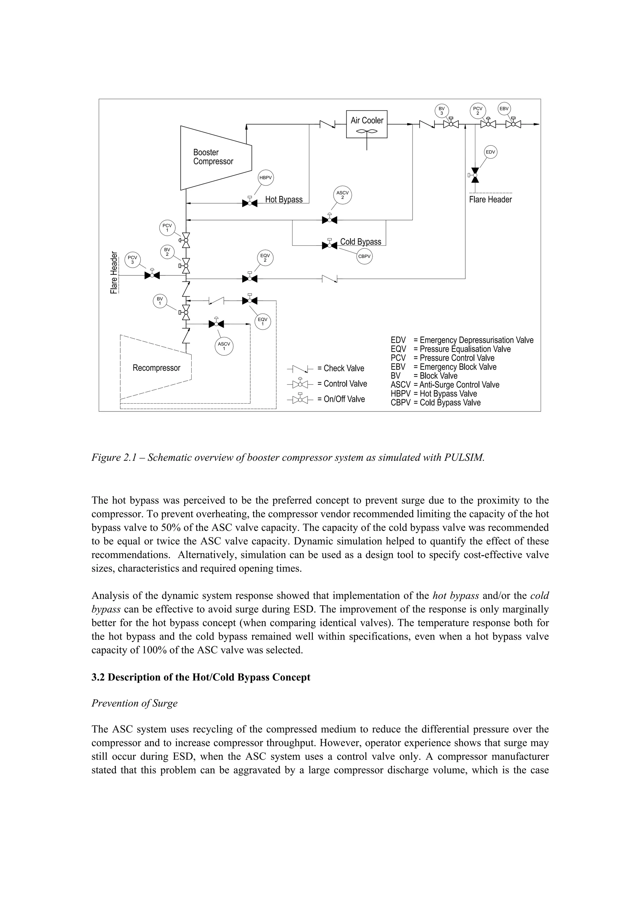
3.4 Simulation Results
The dynamic response of the operating point of the booster compressor as a function of time is presented
in figure 2.2. The trajectory has been plotted for 4 anti-surge concepts (combinations of regular ASC, hot
and cold bypass) and several valve capacities.
Figure 2.2 - Response of compressor operating point during ESD for various anti-surge concepts.
Percentages in the legend indicate the capacity of the Hot/Cold Bypass valves relative to the ASC valve.
The capacity of the ASC valve is 65% of rated compressor flow. The performance curves are shown for
100%, 75%, 50% and 25% of rated speed. Total simulation time is 25 seconds.
ASC = Anti-Surge Control; HB = Hot Bypass; CB = Cold Bypass; PC = performance Curve.
0
5
10
15
20
25
30
35
0.0 0.2 0.4 0.6 0.8 1.0 1.2
Normalised Flow [-]
dp[bar]
Surge Line
Basic ASC
Hot Bypass (50%)
Hot Bypass (100%)
Cold Bypass (100%)
Cold Bypass (200%)
HB (50%) + CB (140%)
PC (100%), t=1.0 sec
PC (75%), t=4.7 sec
PC (50%), t=10 sec
PC (25%), t=19 sec
6. As shown in figure 2.2, simulation confirms that the compressor system will go into surge during ESD
when only relying on the basic ASC system. Implementation of a hot bypass, a cold bypass or a
combination of these will avoid surge during the specified ESD case, if the valve capacity is sufficient. It
is interesting to note that the effect of the hot bypass and the cold bypass on the system response is
comparable when identical valve capacities are selected. This can be seen when comparing the 100%
trajectories of the hot bypass and the cold bypass. Alternatively, the 200% trajectory of the cold bypass is
roughly identical to the ‘190%’ trajectory of the combined hot (50%) and cold bypass (140%).
The resemblance can be explained as follows. The discharge piping of the Booster Compressor can be
seen to act as a single volume. This is because the pressure drop along the discharge piping is relatively
small due to the large pipe diameter. As a consequence, the tie-in point of the anti-surge line or bypass
lines does not significantly affect the response of the compressor operating point for a given valve
capacity. When comparing the effectiveness of the hot and cold bypass to avoid surge, it can be
concluded that both concepts perform similar during the ESD event.
Furthermore it is observed that the check valve at the booster compressor discharge side does not close
upon ESD. This is the case even when the capacity of the hot bypass valve equals the anti-surge valve
capacity. The reason for this is that the regular ASC valve will open fast and simultaneously with the hot
bypass valve, upon ESD. The capacity of the hot bypass valve is insufficient to cause backflow in the
discharge piping.
Conclusions
As the effectiveness to avoid surge is roughly identical for both concepts, it is recommended to
implement the cold bypass concept, even though heating of the recycled gas is only slightly less for the
cold bypass concept during ESD. It should be noted that this conclusion is based on a single pre-defined
ESD case only. Other operational cases, involving events such as failure of (check) valves or different
ESD actions may affect the selection.
References
Bokhorst, E. van, J. Sleijpen, 2001, European Forum for Reciprocating Compressors: Prevention of
Pulsation and Vibration Problems in Ethylene Hyper-compressor Systems, The Hague, The
Netherlands
Egas, B., 2001, Materials and products for noise and vibration control in machinery and transportation
conference (CETIM), vol. 1: PULSIM, a powerful tool to control vibrations in piping systems, Senlis,
France.
Lamey, M.F., W. Schoppa, K.H. Stingl, A.J. Turley jr., 1999, SPE Annual Technical Conference and
Exhibition: Dynamic Simulation of the Europa and Mars Expansion Projects: A New Approach to
Coupled Subsea and Topsides Modeling (SPE 56704), Houston, USA
Peters, M.C.A.M. and H.J. Riezebos, 2001, International Gas Research Conference: Analysis of the
occurrence of flow-induced pulsations in a gas control station, Amsterdam, The Netherlands