Downloaded 180 times


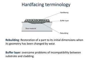

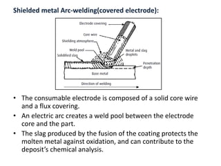


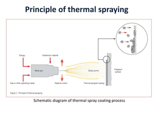
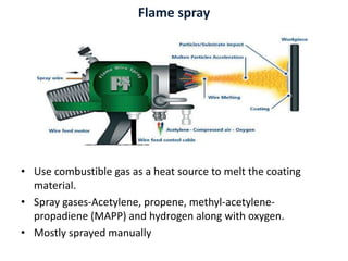


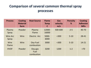
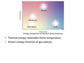
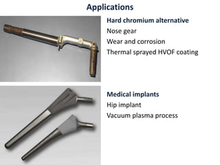


The document discusses newer material processing techniques like surface coating and hardfacing. It describes various types of wear that can occur in machinery and different surface coating methods like thermal spraying and hardfacing. Thermal spraying involves projecting powder or wire material against a substrate using heat sources like plasma or flame to create a coating. Hardfacing is the deposition of a hard surface layer through welding to impart wear resistance. The document provides details on processes like plasma spraying, wire arc spraying and flame spraying and their applications in repairing worn components and improving part lifetime in industries.


![Thin_Film_Technology_introduction[1]](https://cdn.slidesharecdn.com/ss_thumbnails/1b4496c8-2102-411b-8465-a3dd3f398327-150205034538-conversion-gate02-thumbnail.jpg?width=640&height=640&fit=bounds)


