Download to read offline


![ Implement the VHDL portion of coding for synthesis.
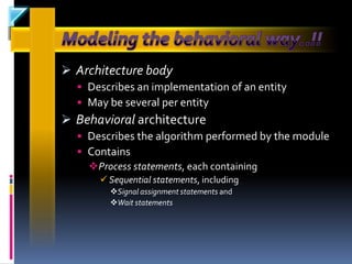
Identify the differences between behavioral and
structural coding styles.
Distinguish coding for synthesis versus coding for
simulation.
Use scalar and composite data types to represent
information.
Use concurrent and sequential control structure to
regulate information flow.
Implement common VHDL constructs (Finite State
Machines [FSMs], RAM/ROM data structures).](https://image.slidesharecdn.com/summertrainingvhdl-130226013350-phpapp02/85/Summer-training-vhdl-35-320.jpg)

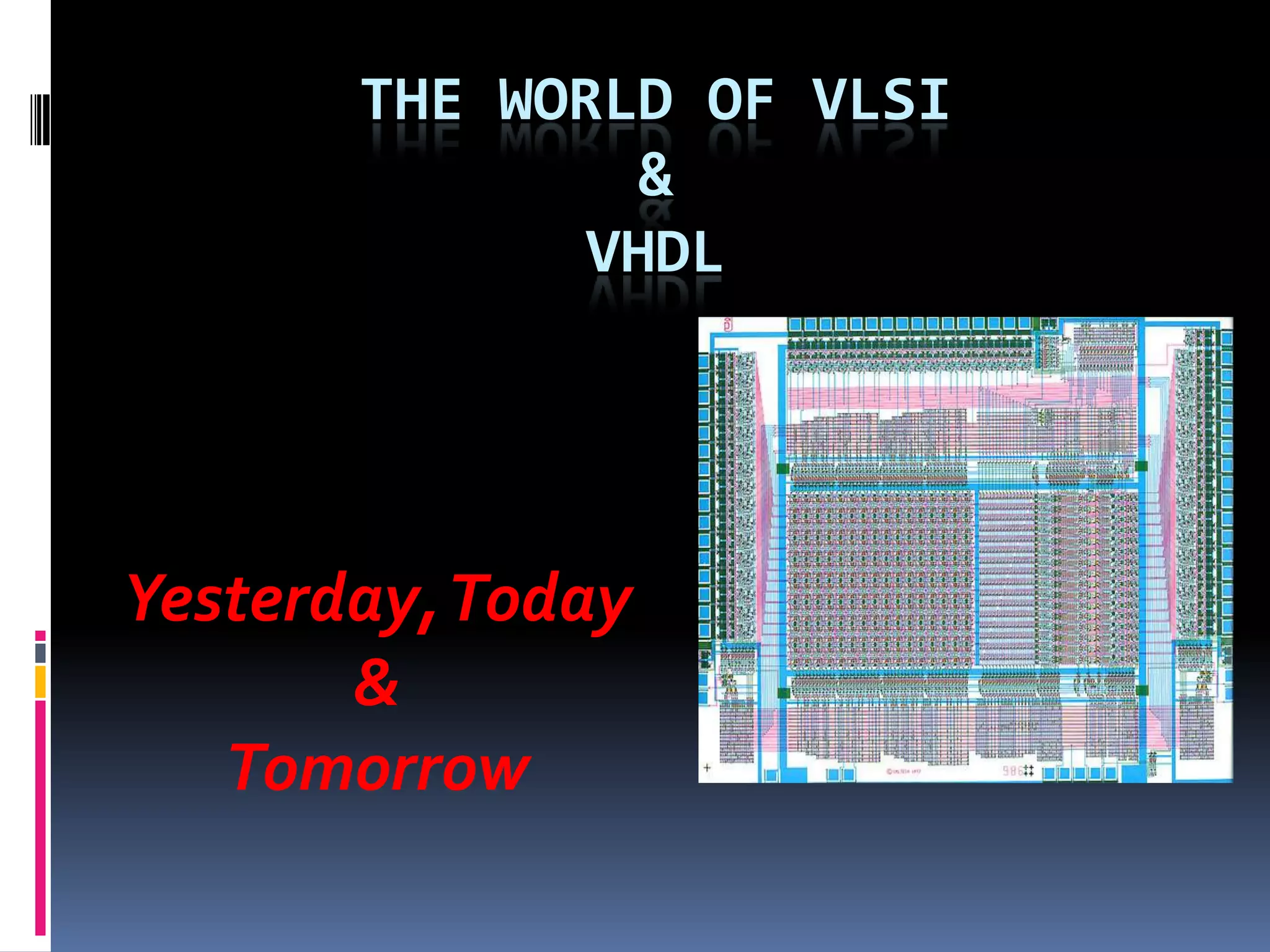
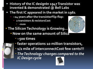
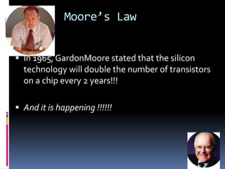
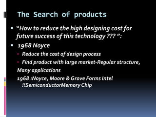
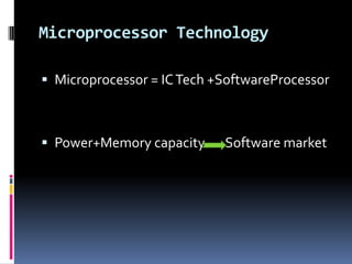
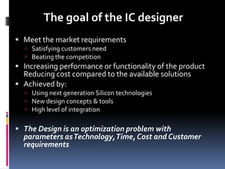
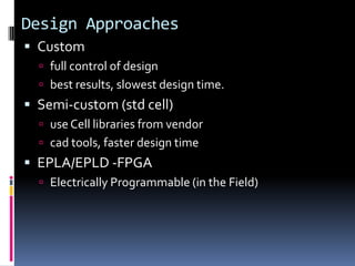
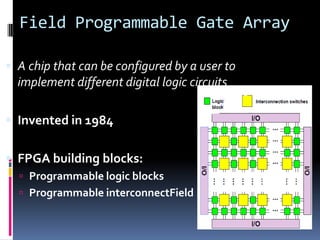
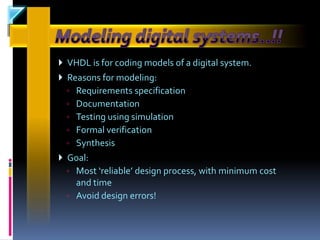
The document discusses the history and evolution of VLSI and VHDL, focusing on the invention of transistors and integrated circuits, advancements in silicon technology, and enhancing design approaches to meet market demands. It highlights the importance of VHDL in modeling digital systems, facilitating design specifications, testing, and simulation, as well as various coding and architecture styles in VHDL. Additionally, it emphasizes cost reduction strategies and design optimization for high-performance integrated circuits.