Downloaded 106 times


![Who first thought of the idea for inflatable buildings? We’ve written about the first person
to actually design and build an air structure, David Geiger, but he wasn’t actually the first
person to think of the idea - only the first to put it into practice. So who did come up with
the idea, then? Well, as with any invention, it’s hard to say who first came up with an idea,
but it’s easy to figure out who first submitted patents for it. In the case of inflatable
structures, the first U.S. patent was submitted by a gentleman named Woldemar A. Bary,
way back on April 28th
, 1955. The patent itself was accepted (presumably) on June 3rd
,
1958 - a full 12 years before the unveiling of Geiger’s air structure at the 70’s World Fair.
After David Geiger created the first air supported structure, the 70’s saw other domes go up
around the world - including the first North American domes of Ralph Farley. [1]
An air-supported (or air-inflated) structure is any building that derives its structural
integrity from the use of internal pressurized air to inflate a pliable material (i.e. structural
fabric) envelope, so that air is the main support of the structure, and where access is via
airlocks. It is usually dome-shaped, since this shape creates the greatest volume for the
least amount of material. To maintain structural integrity, the structure must be pressurized
such that the internal pressure equals or exceeds any external pressure being applied to the
structure (i.e. wind pressure). The structure does not have to be airtight to retain structural
integrity - as long as the pressurization system that supplies internal pressure replaces any
air leakage, the structure will remain stable. All access to the structure interior must be
equipped with some form of airlock - typically either two sets of parallel doors or
a revolving door or both. Air-supported structures are secured by heavy weights on the
ground, ground anchors attached to a foundation, or a combination of these. Among its
many uses are sports and recreation facilities, warehousing and temporary shelters etc. The
structure can be either wholly, partial, or roof-only air supported. A fully air-supported
structure can be intended to be a temporary or semi-temporary facility or permanent,
whereas a structure with only an air-supported roof can be built as a permanent building.
The largest air-supported dome in the world is "The Dome" in Anchorage, Alaska at
180,000 square feet (17,000 m2
). [1]
Fig. 1: “The Dome” in Anchorage
2.0 Types of Air Structures:
Air structures are also known as pneumatic structures. The word “pneumatic” is derived
from the Greek word “pneuma” (meaning breath of air), thus these are the structures which
are supported by air. A pneumatic structure is a constructed form that derives its rigidity
from captured pressurized gas. The term “Pneumatic Structures” encompasses
constructions such as inflatable play areas for children (“bouncy castles”), as well as](https://image.slidesharecdn.com/adrdetrainingreport-160719180242/85/Summer-Engineering-Internship-Training-Report-ADRDE-Agra-DRDO-6-320.jpg)
![covered tennis courts or swimming pools in winter months. When deflated, pneumatic
structures have little rigidity and become loose piles of fabric. When inflated, they attain a
preconceived form and respond dynamically to outside forces, such as wind, rain, and
snow, to keep their form. The inflation, usually by means of a blower or fan, pushes air into
the closed fabric forms to create a pressure differential across the material membrane, with
a higher dynamic pressure inside the form. This creates a tensile force across the
membrane. This tensile force unfolds the fabric until the form is found. To restate, a
pneumatic structure is an inflated membrane experiencing purely tensile forces. Due to
scale and costs, air is usually the choice of inflating gas. There are two major types: single-
membrane and double-membrane. Much of the physics of the two cases boils down to the
same principles, but the two types drive dramatically different architectural forms.
Single-membrane structures use the interior of the bubble as the active, usable space. To
enter a single-membrane pneumatic structure, a person must cross through a threshold,
across which there is the pressure differential. This often requires some kind of an airlock.
Double-membrane structures use pressurized cells as walls, ceilings, and supports. A
person inside a double-membrane is not enclosed within a pressurized space, but is
enclosed by pressurized spaces. [2]
Pneumatic structures can be classified in two categories as mentioned below.
(i) Air Supported Structures
(ii) Air Inflated Structures
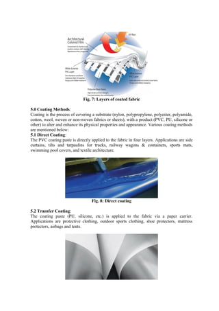
2.1 Air Supported Structures:
The shape of an air-supported structure is limited by the need to have the whole envelope
surface evenly pressurized. If this is not the case, the structure will be unevenly supported,
creating wrinkles and stress points in the pliable envelope which in turn may cause it to
fail. In practice, any air supported surface involves a double curvature. Therefore, the most
common shapes for air-supported structures are hemispheres, ovals, and half cylinders. The
main loads acting against the air-supported envelope are internal air pressure, wind, or
weight from snow build-up. To compensate against wind force and snow load, inflation of
the structure is adjusted accordingly. Modern structures have computer controlled
mechanical systems that monitor dynamic loads and automatically compensate the inflation
for it. The better the quality of the structure, the higher forces and weight it can endure. The
best quality structures can withstand winds up to 120 mph (190 km/h), and snow weight to
40 pounds per square yard (21.7 kilograms per square metre).
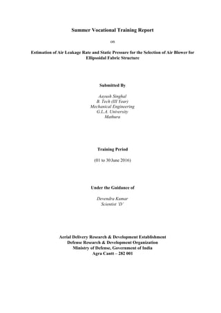
The interior air pressure required for air-supported structures is not as much as most people
expect and certainly not discernible when inside. The amount of pressure required is a
function of the weight of the material - and the building systems suspended on it (lighting,
ventilation, etc.) - and wind pressure. Yet it only amounts to a small fraction of
atmospheric pressure. Internal pressure is commonly measured in inches of water, inAq,
and varies fractionally from 0.3 inAq for minimal inflation to 3 inAq for maximum, with 1
inAq being a standard pressurization level for normal operating conditions. In terms of the
more common pounds per square inch, 1 inAq equates to a mere 0.037 psi (2.54 mbar). [1]](https://image.slidesharecdn.com/adrdetrainingreport-160719180242/85/Summer-Engineering-Internship-Training-Report-ADRDE-Agra-DRDO-7-320.jpg)
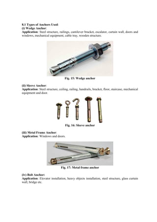
![Fig. 2: Air supported structure for sport activities
2.2 Air Inflated Structures:
An inflatable is an object that can be inflated with a gas, usually with air, but hydrogen,
helium and nitrogen are also used. One of several advantages of an inflatable is that it can
be stored in a small space when not inflated, since inflatables depend on the presence of a
gas to maintain their size and shape. Function fulfilment per mass used compared with non-
inflatable strategies is a key advantage. Stadium cushions, impact guards, vehicle wheel
inner tubes, emergency air bags, and inflatable space structures employ the inflatable
principle. Inflation occurs through several strategies: pumps, ram-air, billowing, and
suction.
There are two types of air inflatable structures: high-pressure and low-pressure. In a high-
pressure inflatable, structural limbs like pillars and arches are built out of a tough, flexible
material and then inflated at a relatively high pressure. These limbs hold up passive
membranes. The space where the visitors or inhabitants stay is at normal atmospheric
pressure. For example, airplane emergency rafts are high-pressure inflatable structures.
Low-pressure inflatables, on the other hand, are slightly pressurized environments
completely held up by internal pressure. In other words, the visitors or inhabitants
experience a slightly higher than normal pressure. Low-pressure inflatables are usually
built of lighter materials. Both types of inflatables (the low-pressure type more so) are
somewhat susceptible to high winds.
Inflatable castles and similar structures are temporary inflatable buildings and structures
that are rented for functions, school and church festivals and village fetes and used for
recreational purposes, mainly used by children. The growth in popularity of moonwalks
has led to an inflatable rental industry which includes inflatable slides, obstacle courses,
games, and more. Inflatables are ideal for portable amusements because they are easy to
transport and store.
These are made of a synthetic fabric, of which different colors have been sewn together in
various patterns. An electric blower constantly forces air into the figure, replacing air lost
through its fabric and seams. They are internally lit by small incandescent light bulbs (also
used in nightlights), which are covered by translucent plastic snap-on globes that protect
the fabric from the heat if they should rest against it. [3]](https://image.slidesharecdn.com/adrdetrainingreport-160719180242/85/Summer-Engineering-Internship-Training-Report-ADRDE-Agra-DRDO-8-320.jpg)
![• Soil anchoring systems include screws, disks, expanding duckbill and
arrowhead anchors.
• Pneumatic structures are designed to uphold or withstand the wind speed of
120 mph and snow load of 40 pounds/yard2
. [2]
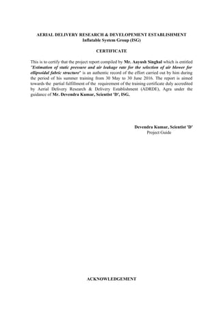
Fig. 5: Air supported structure with subsystems
4.0 Materials Used for the Manufacturing of Envelopes:
For envelopes, the material used should exhibit following properties:
• They should be of light weight.
• They should have high tensile strength and tear resistance.
Materials given below are generally used for the fabrication of the structures.
(i) Fibreglass:
• They have high tensile strength, elasticity and durability.
• They are generally coated with Teflon or silicon to increase resistance to
extreme temperatures and UV radiations.
(ii) Polyester:
• Most common envelope material for small structures.
• PVC is applied to the polyester using a bonding or adhesive agent.
• PVC coated polyester is used for envelopes with small size.
(iii) ETFE:
• It is very energy efficient because of transparency, insulation and UV
resistance.
• It is also light weight and has a life span of 20 years and is recyclable.
(iv) Nylon:
• Vinyl coated nylon has more strength, durability and stretch than polyester.
• They have a higher cost. [1]
Fig. 6: Different types of coated fabrics](https://image.slidesharecdn.com/adrdetrainingreport-160719180242/85/Summer-Engineering-Internship-Training-Report-ADRDE-Agra-DRDO-10-320.jpg)
![Fig. 9: Transfer coating
5.3 Melt Coating:
Through melt coating we produce a film out of different polymers which is then laminated
onto a carrier. This carrier can be a textile, a felt, knitted fabric, another film or paper.
Applications are technical textiles for sewer renovation.
Fig. 10: Melt coating
5.4 Calendaring (Rolling):
We manufacture TPO (thermoplastic polyolefin) and PVC films which are embossed to
give the film a textured aspect. Applications are car dashboards, door panels, sun visors,
wall coverings and pond liners. [4]
Fig. 11: Rolling
6.0 Sealing Methods:
Sealing methods used in fabrication of air structures are mentioned below.
6.1 Radio Frequency Sealing Method:
Also known as high frequency welding and dielectric sealing, this manufacturing process
uses electromagnetic energy and pressure to weld and permanently bond thermoplastic,
vinyl and coated fabrics to create a dimensional product. The RF sealing process is most
often referred to as radio frequency welding because of the way the electrostatic energy and
pressure are used to realign the molecules to form a new, strong bond of the materials
being fused together. Using this RF seal service, a new, one-piece permanent bond is
created that is impenetrable and resistant to tearing. [5]
The radio frequency welding process scrambles the molecules in flexible polymeric
materials to be joined for the dimensional requirements and product functionality. RF
welding is a three-step process involving the preparation and positioning of the
components, adding of electromagnetic energy and pressure to molecularly combine the
materials, and finally, the cooling of the materials. When cooled, the newly formed seam is
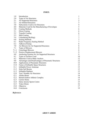
as strong or even potentially stronger than the original material. The RF welding process](https://image.slidesharecdn.com/adrdetrainingreport-160719180242/85/Summer-Engineering-Internship-Training-Report-ADRDE-Agra-DRDO-12-320.jpg)
![can only be used with materials of a polar molecular construction, the most common being
PVC and Polyurethane, although many other coated materials such as nylon are feasible.
RF sealing works much better with stretchable unsupported film type materials such as
TPU and TPE type materials. [6]
Fig. 12: Radio frequency sealing machine [4]
6.2 Adhesive/Gluing:
Gluing can provide an air tight solution, but gluing takes much longer than RF welding and
often uses hazardous solvents that are harmful to the environment. Glued seams are also
subject to failure once the adhesive has worn out. [6]
7.0 Air Blowers for Air Supported Structures:
Blowers are mechanical or electro-mechanical devices used to induce gas flow through
ducting, electronics chassis, process stacks, etc.- wherever flow is needed for exhausting,
aspirating, cooling, ventilating, conveying, and so on. Blowers cool electronic enclosures,
induce drafts in boilers, increase airflow on engines, and are configured in a variety of
designs such as centrifugal flow or rotary lobe styles. Motors usually drive blowers, though
they can be powered by other means such as engines. Often used interchangeably with
“Fans,” blowers are defined by the ASME as having a ratio of discharge pressure over
suction pressure between 1.11 and 1.2, while fans are defined as anything below this ratio
and compressors are defined as anything above it. Some makers of portable fans refer to
their units as blowers even if they do not necessarily conform to the ASME distinction,
which applies to permanently installed industrial process equipment. Another kind of
blower is the mobile or hand held device used for moving fallen leaves. [1]
7.1 Types of Blowers:
7.1.1 Centrifugal Blowers:
Centrifugal blowers use high speed impellers or blades to impart velocity to air or other
gases. They can be single or multi-stage units. Like fans, centrifugal blowers offer a](https://image.slidesharecdn.com/adrdetrainingreport-160719180242/85/Summer-Engineering-Internship-Training-Report-ADRDE-Agra-DRDO-13-320.jpg)
![number of blade orientations, including backward curved, forward curved, and radial.
Blowers can be multi- or variable speed units. They are usually driven by electric motors,
often through a belt and sheave arrangement, but some centrifugal blowers are directly
coupled to drive motors. Fan speed can be changed to vary flow rates by resizing sheaves,
using variable speed drives, etc., but dampers are even more common as a means of
adjusting flow. Fan affinity laws dictate that a percent reduction in speed will produce a
like reduction in flow. [1]
Fig. 13: Centrifugal blower
7.1.2 Positive Displacement Blowers:
Positive Displacement blowers are similar in principle to positive displacement pumps in
that they use mechanical means to squeeze fluid and thereby increase pressure and/or
velocity. Centrifugal designs, on the other hand, impart velocity and pressure to media by
flinging them outward with impellers. Among positive displacement blowers, the Roots, or
rotary lobe, type is common, which uses two counter-rotating lobed rotors to move fluid
through the blower, much the way a gear pump moves oil or other viscous liquids. A
cutaway blower (below) shows one of the two rotors. Positive displacement lowers are
often driven by direct-coupled electric motors but they can be driven by gas engines. [1]
Fig. 14: Positive displacement blower
8.0 Anchoring Systems for Air Supported Structures:
An anchor is used to prevent the structure from drifting from its location due to wind.
There are numerous types of anchors and the heavy ones are normally produced through
casting or drop-forged from carbon steel.](https://image.slidesharecdn.com/adrdetrainingreport-160719180242/85/Summer-Engineering-Internship-Training-Report-ADRDE-Agra-DRDO-14-320.jpg)
![Fig. 18: Bolt anchor
(v) Drop In Anchor:
Application: Drop in anchor is suitable to concrete and natural hard stone. It can be used
for the installation of fire equipment, air conditioner, exhaust duct, upside-down tube,
curtain wall and ceiling etc.
Fig. 19: Drop in anchor
(vi) Tie Wire Anchor:
Application: Tie wire anchor is suitable to concrete and natural hard stone. It can be used
for ceiling and light weight suspension.
Fig. 20: Tie wire anchor
(vii) 4Pcs Heavy Duty Anchor:
Application: Steel structure, bracket, escalator, curtain wall, doors & windows, chairs,
trash can, railings, and deceleration strips etc. [7]](https://image.slidesharecdn.com/adrdetrainingreport-160719180242/85/Summer-Engineering-Internship-Training-Report-ADRDE-Agra-DRDO-16-320.jpg)
![Fig. 21: 4Pcs heavy duty anchor
8.2 Materials Used to Make Anchors:
(i) Steel Cables:
Steel wires are twisted into strands which are then twisted around a core to form the cable.
(ii) Ballasts:
Materials for ballasts of smaller structures include sand bags, concrete blocks or bricks.
The ballasts must be placed around the perimeter of the structure to evenly distribute the
load. [7]
9.0 Advantages and Disadvantages of Pneumatic Structures:
(i) Advantages:
• Considerably lower initial cost than conventional buildings.
• Lower operating costs due to simplicity of design (wholly air-supported structures
only).
• Easy and quick to set up, dismantle, and relocate (wholly air-supported structures
only).
• Unobstructed open interior space, since there is no need for columns.
• Able to cover almost any project.
• Custom fabric colours and sizes, including translucent fabric, allowing natural
sunlight in.
(ii) Disadvantages:
• Continuous operation of fans to maintain pressure, often requiring redundancy or
emergency power supply.
• Dome collapses when pressure lost or fabric compromised.
• Cannot reach the insulation values of hard-walled structures, increasing
heating/cooling costs.
• Limited load-carrying capacity.
• Continuous operation of fans and blowers to maintain pressure. [1]
10.0 Applications of Pneumatic Structures
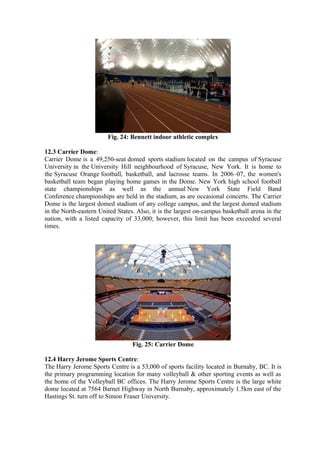
(i) Sports and Recreation:
It has the ability to span greater distances without beams and columns. For example,
American football and baseball grounds.](https://image.slidesharecdn.com/adrdetrainingreport-160719180242/85/Summer-Engineering-Internship-Training-Report-ADRDE-Agra-DRDO-17-320.jpg)
![Fig. 22: Air supported sports dome
(ii) Military Structures:
• For storage and emergency medical operations.
• To protect radar stations from adverse weather conditions. [2]
11.0 Future of Inflatable Space Structures:
11.1 Inflatable Power Antennae:
• The Power Antennae utilizes an inflatable parabolic reflector.
• Parabolic reflector acts as a solar concentrator and focuses energy concentrator and
focuses energy onto a solar array.
• A beam splitter is mounted in front of the array to deflect RF onto a feed.
• The feed is used to separate optical from RF energy.
• Can be used for deep space power generation and high gain power generation and
high gain RF communications concurrently. [8]
11.2 Solar Sail Booms:
• Solar sails are devices that reflect photons from the reflect photons from the sun
and convert some sun and convert some energy into thrust.
• Inflatable rigidizable booms can be used for booms can be used for support.
• Inflation gas is introduced at the base.
• Utilizes the concept of glass transition glass transition rigidization.
• Since tube is rigidized, it can withstand substantial loads after deployment. [9]
11.3 Inflatable Radiator:
• High power generation on Space-based defence systems require large amounts of
heat rejection.
• Inflatable radiator can capture heat during power generation periods and radiate
into space power generation periods.
• During power generation phase, radiator is extended out spacecraft while filled
with waste heat.
• Steam is condensed gradually as heat is radiated into space.](https://image.slidesharecdn.com/adrdetrainingreport-160719180242/85/Summer-Engineering-Internship-Training-Report-ADRDE-Agra-DRDO-18-320.jpg)
![• Radiator is retracted during this period to maintain constant saturation pressure.
This also keeps radiator constant saturation pressure. This also keeps radiator
protected from space debris. [10]
12.0 Top 5 Notable Air Structures:
12.1 Alaska Dome:
At 180,000 square feet, The Dome is officially the largest sports complex of its kind on the
planet. Held down with pipes and cables plunging 40 feet into the ground, supported by
pressurized air, The Dome houses a 400-meter USA Track & Field certified track, full-size
soccer field, full-size football field, weight equipment, batting cages and much more. Snow
and wind sensors automatically increase or decrease pressure and temperature of The
Dome, keeping it at 15 to 17 lbs of air pressure per square inch, creating an hyperbaric
chamber.
Fig. 23: Alaska dome
12.2 Bennett Indoor Athletic Complex:
The Bennett Indoor Athletic Complex is an air-supported structure that provides an indoor
venue for athletics to the Toms River Regional Schools. It is part of the Bennett Complex,
which also features outdoor facilities. The Bennett Complex is located between Hooper
Elementary and Toms River Intermediate East at 1519 Hooper Avenue in Toms River. It is
named after long time Superintendent John Bennett, who served the district from 1960-
1977. Amongst other events, the Bennett Complex has hosted the track meet component of
the NJSIAA Tournament of Champions in 2007, 2008, 2009, 2010, 2011, 2012 (for indoor
athletics only), 2013, and 2014. The Indoor Athletic Complex is also known as The
Bubble, and is home to many New Jersey State indoor athletic meets (including state
championships). The Indoor Complex features a 200 meter six-lane track with and eight-
lane straightaway, a Finish Lynx electronic timing system, and accommodates field events
such as shot put, high jump, pole vault, long jump, and triple jump. The Indoor Complex
was first installed for the 2006-2007 school year. The Indoor Complex was damaged by
Hurricane Sandy, but was repaired and reopened in January 2013.](https://image.slidesharecdn.com/adrdetrainingreport-160719180242/85/Summer-Engineering-Internship-Training-Report-ADRDE-Agra-DRDO-19-320.jpg)
![Fig. 26: Harry Jerome sports centre for volleyball
12.5 Tokyo Dome:
Tokyo Dome is a stadium located in Bunkyo, Tokyo, Japan. Construction on the stadium
began on May 16, 1985, and it opened on March 17, 1988. It was built on the site of the
Velodrome, adjacent to the predecessor ballpark, Korakuen Stadium. It has a maximum
total capacity of 55,000 depending on configuration, with an all-seating configuration of
42,000.Tokyo Dome's original nickname was "The Big Egg", with some calling it the
"Tokyo Big Egg". Its dome-shaped roof is an air-supported structure, a flexible membrane
held up by slightly pressurizing the inside of the stadium. It is the home field of the
Yomiuri Giants baseball team, and has also hosted music concerts, basketball, American
football and association football games, as well as puroresu (pro-wrestling) matches, mixed
martial arts events, kickboxing events, and monster truck races. It is also the location of the
Japanese Baseball Hall of Fame which chronicles the history of baseball in Japan. [11]
Fig. 27: Tokyo dome](https://image.slidesharecdn.com/adrdetrainingreport-160719180242/85/Summer-Engineering-Internship-Training-Report-ADRDE-Agra-DRDO-21-320.jpg)

![References:
[1] https://en.wikipedia.org/wiki/Air-supported_structure_and-airblowers
[2] https://www.slideshare.net/Krishnagnr/pneumatic-structures-55250260
[3] https://en.wikipedia.org/wiki/Inflatable_building
[4] www.sioen.com/technical-textiles/5-coating-techniques
[5] Espalin, D., Medina, F., Arcaute, K., Zinniel, B., Hoppe, T., Wicker, R., (2009).
Effects of Vapour Smoothing on ABS Part Dimensions. Proceedings from Rapid
2009 Conference & Exposition, Schaumburg, IL
[6] Rashilla, R.J., (1993). All-composite pressure vessels for natural gas vehicle (NGV)
fuel tank. Proceedings of the Conference for Advanced Composites Technologies,
Dearborn, MI, pp. 8–11
[7] http://www.ucanfast.com/pages/mechanicalanchors.php?category=6
[8] http://lgarde.com/people/papers/2003-4659/index.html
[9] http://lgarde.com/people/papers/powant/index.html
[10] http://spaceflightnow.com/news/n0006/26spaceinflate
[11] https://www.slideshare.net/mobile/premiereinflatable/top-5-air-supported-structure](https://image.slidesharecdn.com/adrdetrainingreport-160719180242/85/Summer-Engineering-Internship-Training-Report-ADRDE-Agra-DRDO-26-320.jpg)

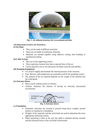
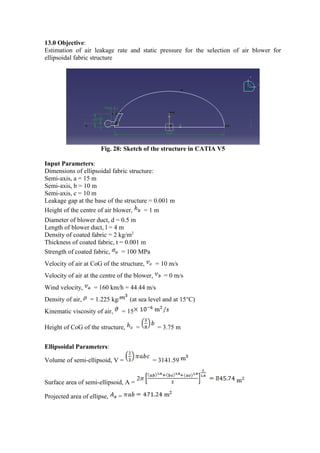
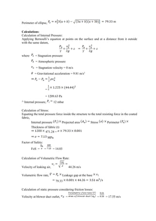
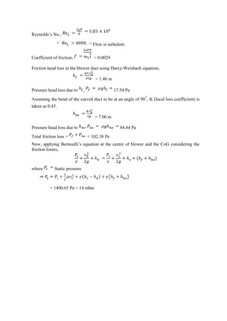
The summer vocational training report by Aayush Singhal details the estimation of air leakage rates and static pressure for selecting air blowers suitable for ellipsoidal fabric structures, conducted at the Aerial Delivery Research & Development Establishment (ADRDE), Agra. The report covers various aspects of air-supported structures, including their types, subsystems, materials, coating and sealing methods, and applications in different fields. The training experience was guided by Devendra Kumar and provided substantial knowledge regarding pneumatic structures and their functionalities.