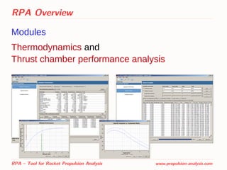
RPA is a computational tool for analyzing rocket propulsion systems in conceptual and preliminary design phases. It features modules for thermodynamics analysis, thrust chamber performance prediction, chamber sizing, nozzle contour design, and thermal analysis. The tool uses simplified physical models and semi-empirical relationships to rapidly analyze systems with minimum input parameters while providing sufficient accuracy for early design studies. RPA assists in education and allows variation of design parameters to assess impacts on performance.

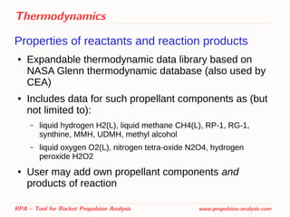
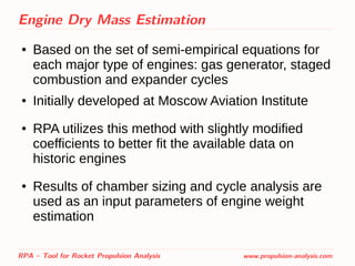
![Performance Analysis
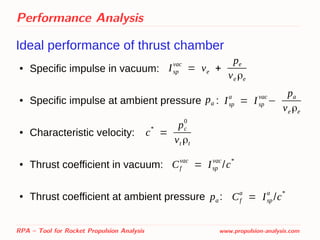
Delivered performance of thrust chamber
● Specific impulse in vacuum:
● Specific impulse at ambient pressure :
● Characteristic velocity:
● Thrust coefficient in vacuum:
● Thrust coefficient at ambient pressure :
Correction factors are obtained from semi-empirical relations [1]
[1] For more details see: Ponomarenko, A. RPA: Tool for Rocket Propulsion Analysis. Assessment of
Delivered Performance of Thrust Chamber. March 2013.
RPA – Tool for Rocket Propulsion Analysis www.propulsion-analysis.com
(Isp
vac
)d = ζc ζn Isp
vac
(Isp
a
)d=(Isp
vac
)d−
pa
ve ρe
(Cf
vac
)d = ζn Cf
vac
(Cf
a
)d = ζn Cf
a
(c*
)d = ζc c*
pa
pa](https://image.slidesharecdn.com/sp2014pres2967435ponomarenko-140522153109-phpapp01/85/RPA-Tool-for-Rocket-Propulsion-Analysis-14-320.jpg)
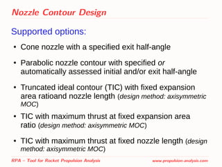
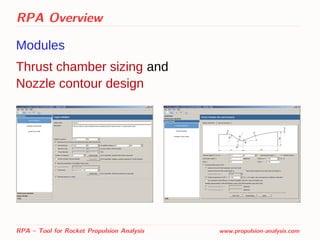
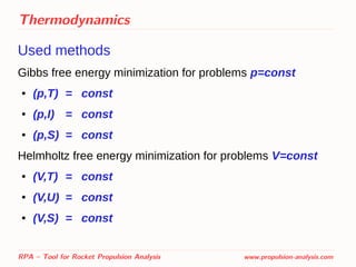
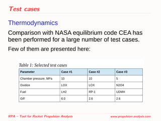
![Nozzle Contour Design
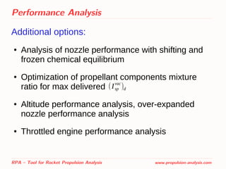
Direct optimization of nozzle contour
RPA – Tool for Rocket Propulsion Analysis www.propulsion-analysis.com
Cf = (Cf )2D (1−ζf ) → max
(Cf )2D = 2
Ae
At
∫
0
1
(1−
γ−1
γ+1
λ
2
)
1
γ−1
[1+λ
2 γ(2cos
2
β−1)+1
γ+1 ]̄r d̄r
To obtain the contour with the
maximum thrust coefficient at
specified conditions (area
ratio or nozzle length)
ζf = 1 −
2̄δe
**
1 +
1
γ Me
2
δ**
=
( 2
γ−1)
0.1
Rew0
0.2
(
0.015
̄Tw
0.5
)
0.8 (1+
γ−1
2
Mwe
2
)
γ+1
2(γ−1)
Mw
ν+1
̄S0.2
̄re
2
[∫
0
̄S
̄r1.25
M1+1.25ν
(1+
γ−1
2
Mw
2
)
1.36 γ−0.36
γ−1
d ̄S
]
0.8](https://image.slidesharecdn.com/sp2014pres2967435ponomarenko-140522153109-phpapp01/85/RPA-Tool-for-Rocket-Propulsion-Analysis-19-320.jpg)
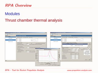
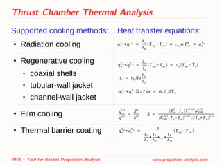
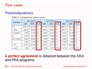
![Thrust Chamber Thermal Analysis
Supported methods to obtain gas-side heat flux:
● Radiation heat transfer:
● Convective heat transfer
Bartz method:
Ievlev method[1,2]
:
1. Lebedinsky E.V., Kalmykov G.P., et al. Working processes in liquid-propellant rocket engine and their simulation. Moscow,
Mashinostroenie, 2008
2. Vasiliev A.P., Kudryavtsev V.M. et al. Basics of theory and analysis of liquid-propellant rocket engines, vol.2. 4th Edition. Moscow,
Vyschaja Schkola, 1993
RPA – Tool for Rocket Propulsion Analysis www.propulsion-analysis.com
qr=εe σ(εr
T ∞
T∞
4
− εr
T w
Tw
4
)
εe=εw /[1−(1−εw)(1−εr
T w
)]
qw = αT (Taw−Tw) αT =
[0.026
Dt
0.2
(μ∞
0
)0.2
cp∞
0
(Pr∞
0
)
0.6 (pc
0
c
* )
0.8
(Dt
R )
0.1
] (At
A )
0.9
σ
σ=
[1
2
Tw
Tc
0 (1+
γ−1
2
M
2
)+
1
2]
−0.68
[1+
γ−1
2
M
2
]
−0.12
Taw=Tc
0
[1+Pr1/3
(γ−1
2 )M2
1+(γ−1
2 )M2
]
qw = αT ρx v∞(I∞
0
−Iw) αT =
( z
zT
)
0.089 Pr−0.56
(1−0.21
1−Pr
Pr
4/3
β
2
1− ̄Tw
)
0.9225
(307.8+54.8 log
2
( Pr
19.5))Pr
0.45
z
0.08
−650](https://image.slidesharecdn.com/sp2014pres2967435ponomarenko-140522153109-phpapp01/85/RPA-Tool-for-Rocket-Propulsion-Analysis-20-320.jpg)
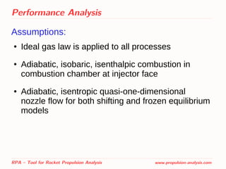
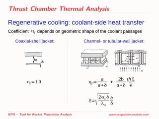
![Thrust Chamber Thermal Analysis
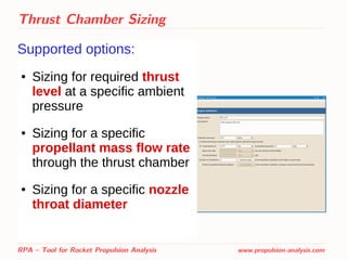
Regenerative cooling: coolant-side heat transfer
RPA – Tool for Rocket Propulsion Analysis www.propulsion-analysis.com
Nu = 0.021Rec
0.8
Prc
0.4
(0.64+0.36
T c
Twc
) for kerosene
[1]
for liquid hydrogen
[1]
for methane
[1]
for other coolants
[2]
Nu = 0.033Rec
0.8
Prc
0.4
(Tc
Twc
)
0.57
Nu = 0.0185 Rec
0.8
Prc
0.4
(Tc
T wc
)
0.1
Nu = 0.023Rec
0.8
Prc
0.4
1. Lebedinsky E.V., Kalmykov G.P., et al. Working processes in liquid-propellant rocket engine and their simulation. Moscow,
Mashinostroenie, 2008
2. Vasiliev A.P., Kudryavtsev V.M. et al. Basics of theory and analysis of liquid-propellant rocket engines, vol.2. 4th Edition. Moscow,
Vyschaja Schkola, 1993](https://image.slidesharecdn.com/sp2014pres2967435ponomarenko-140522153109-phpapp01/85/RPA-Tool-for-Rocket-Propulsion-Analysis-22-320.jpg)
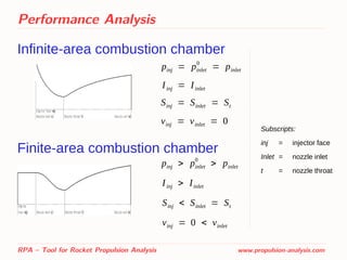
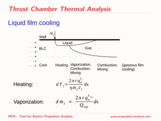
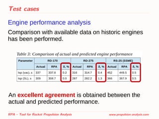
![Thrust Chamber Thermal Analysis
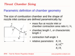
Gaseous film cooling
RPA – Tool for Rocket Propulsion Analysis www.propulsion-analysis.com
BLC
Core (O/F)core
, Tcore
(O/F)f
, Tf[(O/F)b
, Tb
]1
mf
.
[(O/F)b
, Tb
]2
Wall
Combustion,Mixing
At each point downstream of
injection point, the mixing rate is
a function of distance from the
injection point and the relative
mass flow rate of the film.](https://image.slidesharecdn.com/sp2014pres2967435ponomarenko-140522153109-phpapp01/85/RPA-Tool-for-Rocket-Propulsion-Analysis-24-320.jpg)
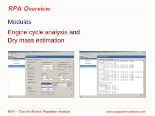
![Engine Cycle Analysis
Parameters of components
The pump shaft power:
The power developed by
gas turbine:
The power developed by
hydraulic turbine:
RPA – Tool for Rocket Propulsion Analysis www.propulsion-analysis.com
Np =
˙m
ηp
( pout− pin)
ρ
Nt = ˙mt ηt
γ
γ−1
R0
Tt in
0
[1−(1
δt
)
γ−1
γ
]
Nt = ˙mt ηt
( pout−pin)
ρ](https://image.slidesharecdn.com/sp2014pres2967435ponomarenko-140522153109-phpapp01/85/RPA-Tool-for-Rocket-Propulsion-Analysis-29-320.jpg)
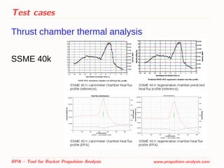
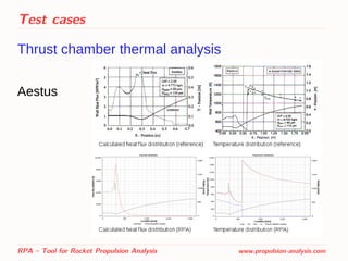
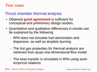
![Test cases
Thrust chamber thermal analysis
Comparison with available reference data has been
performed:
– SSME 40k [1]
– Aestus [2]
RPA – Tool for Rocket Propulsion Analysis www.propulsion-analysis.com
[1] Scaling Techniques for Design, Development, and Test.
Carol E. Dexter, Mark F. Fisher, James R. Hulka, Konstantin P. Denisov,
Alexander A. Shibanov, and Anatoliy F. Agarkov
[2] Simulation and Analysis of Thrust Chamber Flowfields: Storable Propellant Rockets.
Dieter Preclik, Oliver Knab, Denis Estublier, and Dag Wennerberg](https://image.slidesharecdn.com/sp2014pres2967435ponomarenko-140522153109-phpapp01/85/RPA-Tool-for-Rocket-Propulsion-Analysis-35-320.jpg)


![ANIMAL_CELL_,_TISSUE_AND_ORGAN_CULTURE[1].pptx](https://cdn.slidesharecdn.com/ss_thumbnails/animalcelltissueandorganculture1-260204172026-4462b440-thumbnail.jpg?width=640&height=640&fit=bounds)


