1 | P a g e 4s6ggs C Right
2 | P a g e 4s6ggs C Right
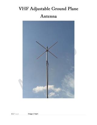
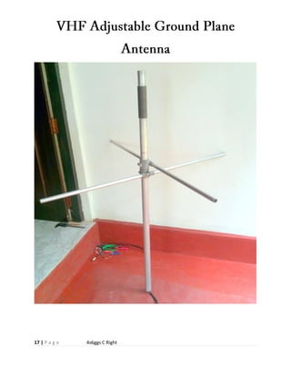
adjustable ground plane antenna designed primarily as a VHF base station antenna when a high gain
antenna is not required or justified. As it is adjustable over the entire VHF high band 144 to 174MHZ
The antenna is constructed of an aluminium mounting tube with the radiating element enclosed by a UV
stabilis,piece design. The antenna is DC grounded for lightning protection and reduction of static noise.
omnidirectional unity gain adjustable ground plane
quarter wave radiating element with the radials acting as a counterpoise.
Specifications
 Impedance at resonance: 50 ohms
 Resonant Frequency: 144-174 MHz (adjustable)
 Frequency range with SWR below 1.1.5 MHz (adjustable)
 Power handling capability: greater than 200 Watts
 Radiation Polarity: vertical
 Directionality: omnidirectional
 Angle of maximum radiation: approximately 45 degrees from horizontal
Materials
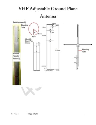
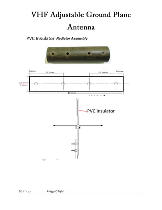
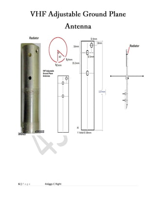
 1120mm length of 38mm T2mm Aluminum pipe, cut to resonance 1Nos.
Radiator
 137mm length of 38mm T2mm Aluminum pipe, cut to resonance 1Nos
Radiator
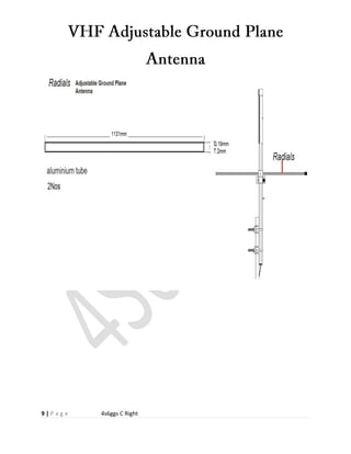
 1131mm length of 19mm T 2mm Aluminum pipe, cut to resonance 2Nos
Radials
 38mm Aluminum pipe end cap 1 No’s
 38mm I.D. compression pipe clamp 2 no’s for Radials
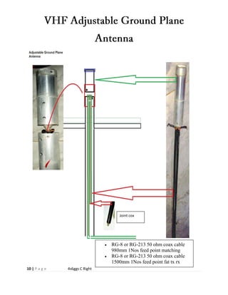
 RG-8 or RG-213 50 ohm coax cable 980mm 1Nos feed point matching
 RG-8 or RG-213 50 ohm coax cable 1500mm 1Nos feed point fat tx rx
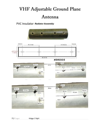
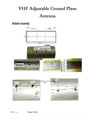
 PVC tube ID 38mm T 3mm L152mm insulator
3 | P a g e 4s6ggs C Right
Construction
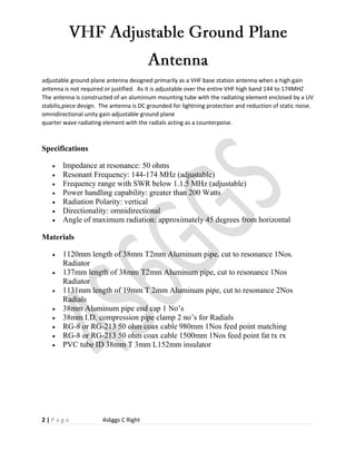
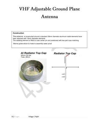
The antenna is constructed around a standard 38mm diameter aluminum radial elements have
been attached with 19mm diameter elements
The radiating element is fitted to coax center pin and positioned with two part coax matching
Marine grade silicon to make to assembly water proof.
4 | P a g e 4s6ggs C Right
5 | P a g e 4s6ggs C Right
6 | P a g e 4s6ggs C Right
7 | P a g e 4s6ggs C Right
8 | P a g e 4s6ggs C Right
9 | P a g e 4s6ggs C Right
10 | P a g e 4s6ggs C Right
 RG-8 or RG-213 50 ohm coax cable
980mm 1Nos feed point matching
 RG-8 or RG-213 50 ohm coax cable
1500mm 1Nos feed point fat tx rx
Joint cox
11 | P a g e 4s6ggs C Right
The actual impedance of the antenna at its center feed point varies with frequency and antenna
height.
The transmission line is a balanced conductor pair with a 50-Ω impedance. Coax cable with a 50-
Ω characteristic impedance (Zo)
Coax is an unbalanced line since RF current will flow on the outside of the coax shield, creating
some undesirable induced RF in nearby devices, although the antenna will work well enough.
The best feed method is to use
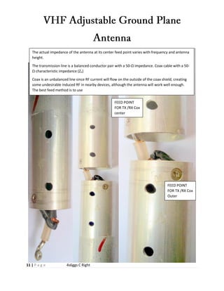
FEED POINT
FOR TX /RX Cox
center
FEED POINT
FOR TX /RX Cox
Outer
12 | P a g e 4s6ggs C Right
13 | P a g e 4s6ggs C Right
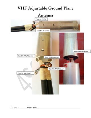
Feed for TX /RX
Feed for Machine
Machin
Feed for TX /RX center
Feed for TX /RX outer
Feed for Mac outer
Feed for Mac center
Feed for Mac center
14 | P a g e 4s6ggs C Right
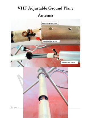
Feed for Mac center
Feed for Mac center
Feed for TX /RX center
15 | P a g e 4s6ggs C Right
16 | P a g e 4s6ggs C Right
17 | P a g e 4s6ggs C Right