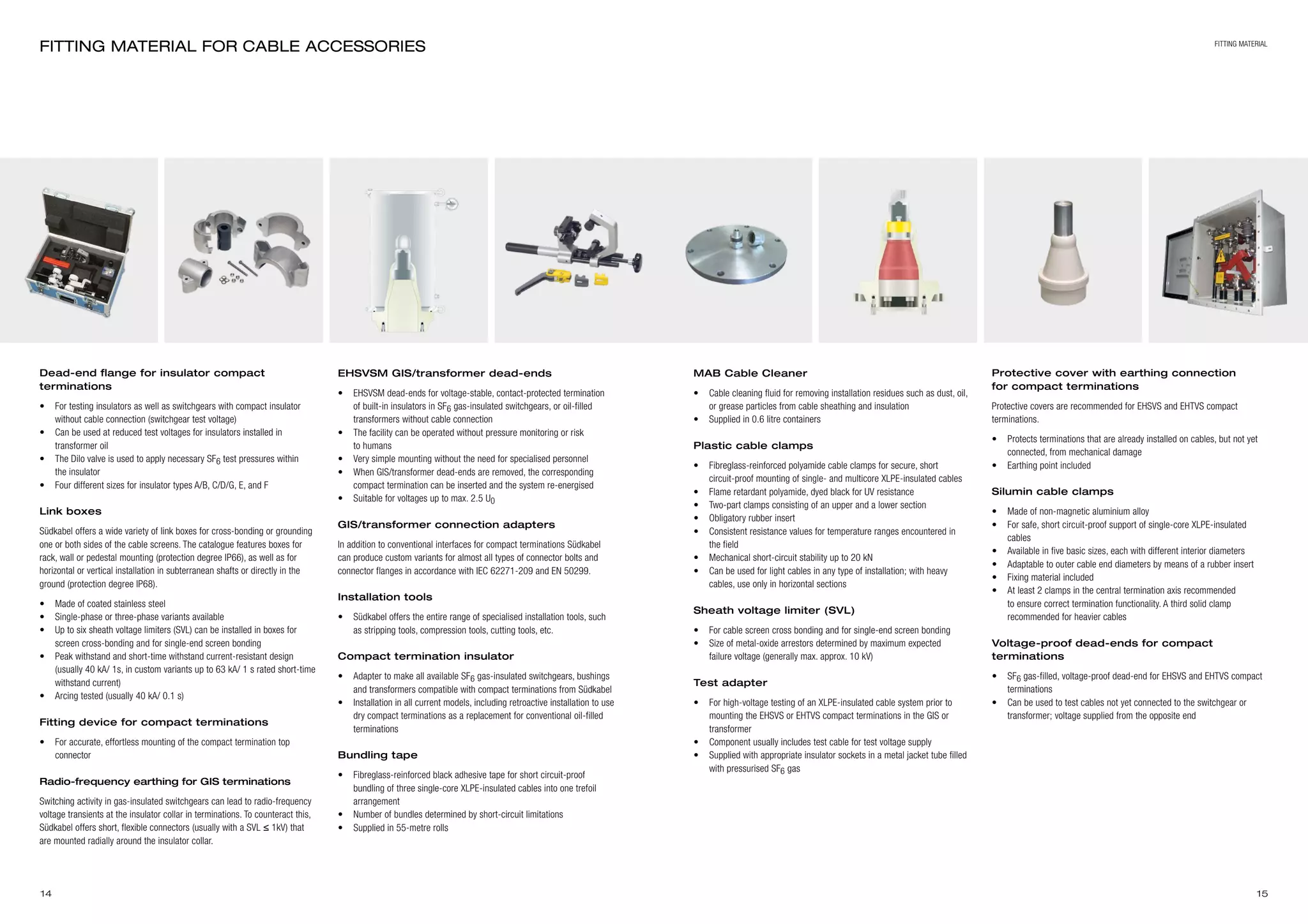
Downloaded 26 times

![8 9
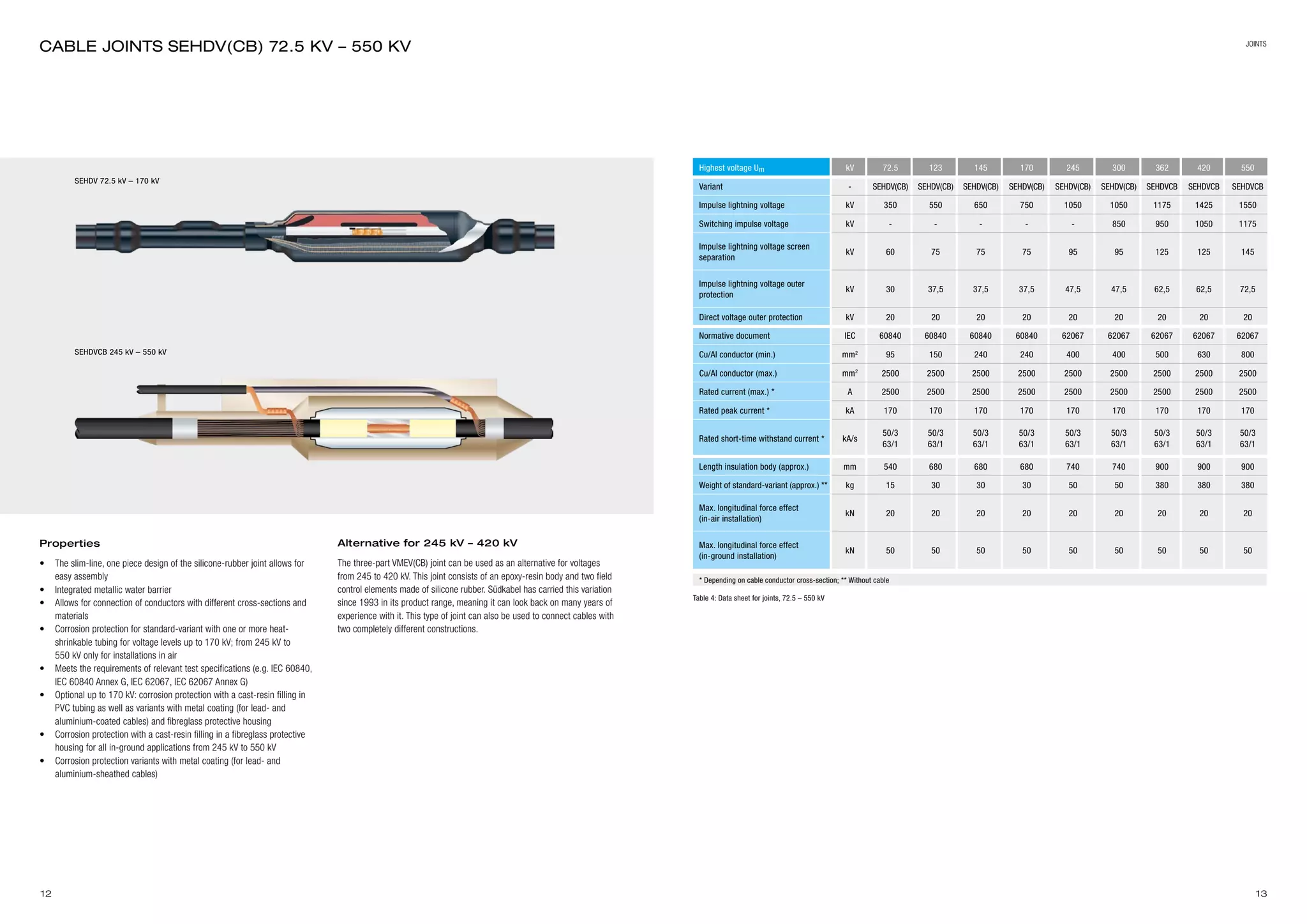
Variants EHFVC (with composite insulator)
and EHFV (with porcelain insulator)
• Primary component: composite insulator made of fibreglass-reinforced
plastic support tubing with integrally cast sheds of high-grade silicone
rubber, or with porcelain insulator
• Field control by means of a push-on stress cone made of silicone
rubber that also seals the base of the termination
• Filled with a synthetic insulating liquid (polyisobutylene)
• Optional equipment: flashover protective fittings (arcing horns)
• Also available: insulated installation with special cast-resin
post insulators
• Meets the requirements of relevant test specifications (e.g. IEC 60840,
IEC 62067, IEC 60815)
• Insulators with extended creepage paths for use in highly polluted
areas are available
• Cantilever load at conductor bolt dependent on type and length of
insulator
• Possible modification of external insulation to correct for atmospheric
conditions (for installations at altitudes > 1000 m) by increasing the
arcing distance with longer insulators or by using accessories with a
higher voltage level
• Short overall height insulator up to a maximum of 30° inclination
1. Top connector
2. Protection ring fitting
3. Composite insulator
4. Porcelain insulator
5. Insulation liquid
6. Stress cone
7. Base plate
8. Screen connection
EHFVC to 170 kV EHFV to 170 kV EHFVC to 550 kV EHFV to 550 kV
Table 2: Data sheet for outdoor terminations filled with liquid plate
Highest voltage Um kV 72.5 123 145 170 245 300 362 420 550
Variant with composite insulator - EHFVC EHFVC EHFVC EHFVC EHFVC EHFVC EHFVC EHFVC EHFVC
Variant with porcelain insulator - EHFV EHFV EHFV EHFV EHFV EHFV EHFV EHFV EHFV
Impulse lightning voltage kV 350 550 650 750 1050 1050 1175 1425 1550
Switching impulse voltage kV - - - - - 850 950 1050 1175
Normative document IEC
60840
60815
60840
60815
60840
60815
60840
60815
62067
60815
62067
60815
62067
60815
62067
60815
62067
60815
Cu/Al conductor (min.) mm² 95 150 240 240 400 400 500 630 800
Cu/Al conductor (max.) mm² 2500 2500 2500 2500 2500 2500 2500 2500 2500
Rated current (max.) * A 3150 3150 3150 3150 3150 3150 3150 3150 3150
Rated peak current * kA 170 170 170 170 170 170 170 170 170
Rated short-time withstand current * kA/s
50/3
63/1
50/3
63/1
50/3
63/1
50/3
63/1
50/3
63/1
50/3
63/1
50/3
63/1
50/3
63/1
50/3
63/1
Standard pollution class -
≥ d/III
heavy
≥ d/III
heavy
≥ d/III
heavy
≥ d/III
heavy
≥ d/III
heavy
≥ d/III
heavy
≥ d/III
heavy
≥ d/III
heavy
≥ d/III
heavy
Length with class d/III (approx.)
EHFVC/EHFV [L]
mm
1350/
1020
1710/
1490
1980/
1700
2290/
1950
2590/
2540
3070/
3040
3580/
-
4100/
-
5020/
5130
Weight with class d/III (approx.) EHFVC/EHFV ** kg
80/
-
90/
175
95/
195
105/
235
370/
470
390/
570
780/
-
960/
-
1100/
1400
Base plate dimensions [a] mm 420 420 420 420 600 600 700 700 700
Hole distance [b] mm 345 345 345 345 500 500 600 600 600
Hole diameter [Ø c] mm 18 18 18 18 23 23 23 23 23
Bolt diameter [Ø d] (≤1000 mm2
/>1000 mm2
) mm 30/50 30/50 30/50 30/50 30/50 30/50 30/50 30/50 30/50
Bolt length [I] mm 100 100 100 100 100 100 100 100 100
* Depending on cable conductor cross-section; ** Without cable
Outdoor TERMINATIONS FILLED WITH liquid INSULATION
a
a
b
b
Ø c
outdoor termination
Base plate dimensions](https://image.slidesharecdn.com/sudkabelehvxlpecableterminationscablejoints-150803085445-lva1-app6891/75/Sudkabel-EHV-XLPE-Cable-Terminations-Cable-Joints-5-2048.jpg)
![10 11
Table 3: Data sheet for gas-filled outdoor terminations
Base plate dimensionss
Highest voltage Um kV 245 300 362 420 550
Variant with composite insulator - EHFVCS EHFVCS EHFVCS EHFVCS EHFVCS
Impulse lightning voltage kV 1050 1050 1175 1425 1675
Switching impulse voltage kV - 850 950 1050 1240
Normative document IEC
62067
60815
62067
60815
62067
60815
62067
60815
62067
60815
Cu/Al conductor (min.) mm² 400 400 500 630 800
Cu/Al conductor (max.) mm² 2500 2500 2500 2500 2500
Rated current (max.) * A 3150 3150 3150 3150 3150
Rated peak current * kA 170 170 170 170 170
Rated short-time withstand current * kA/s
50/3
63/1
50/3
63/1
50/3
63/1
50/3
63/1
50/3
63/1
Standard pollution class -
≥ d/III
heavy
≥ d/III
heavy
≥ d/III
heavy
≥ d/III
heavy
≥ d/III
heavy
Length with class d/III (approx.) [L] mm 3120 3120 3650 5240 5240
Weight with class d/III (approx.) ** kg 350 350 650 800 800
Max. longitudinal power effect kN 2 2 2 2 2
Base plate dimensions [a] mm 600 600 800 800 800
Hole distance [b] mm 500 500 700 700 700
Hole diameter [Ø c] mm 23 23 23 23 23
Bolt diameter [Ø d] mm 60 60 60 60 60
Bolt length [I] mm 100 100 100 100 100
* Depending on cable conductor cross-section; ** Without cable
GAS-FILLED outdoor TERMINATIONS
a
a
b
b
Ø c
Advantages
• Considerably shorter on-site assembly time compared with terminations
filled with liquid insulation
• Very short cable length to work with
• Can be installed at any position depending on shed alignment
• Plug-in system allows for insulated assembly
Properties
• Composite insulation of fibreglass-reinforced plastic support tubing
with integrally cast sheds of high-grade silicone rubber
• Integrated compact termination as a component of the electric
field control
• The socket-type epoxy-resin insulator is fastened to the base plate of
the termination
• Permanent elastic field control made of silicone rubber connected to
the insulator via spring assemblies
• Filled with high-grade insulating gas
• Optional equipment: flashover protective fittings (arcing horns)
• Meets the requirements of relevant test specifications (e.g.
IEC 62067, IEC 60815)
• Insulators with extended creepage paths for use in highly polluted
areas
• Cantilever load at conductor bolt dependent on type and length of
insulator being used
• Possible modification of external insulation to correct for atmospheric
conditions (for installations at altitudes > 1000 m) by increasing the
arcing distance with longer insulators or by using higher-voltage
accessories
• Also available with optional heating system for use in very low-
temperature environments
EHFVCS to 550 kV
outdoor terminations
1. Top connector
2. Protection ring fitting
3. Composite insulation
4. Insulating gas
5. Compact termination
6. Screen connection](https://image.slidesharecdn.com/sudkabelehvxlpecableterminationscablejoints-150803085445-lva1-app6891/75/Sudkabel-EHV-XLPE-Cable-Terminations-Cable-Joints-6-2048.jpg)

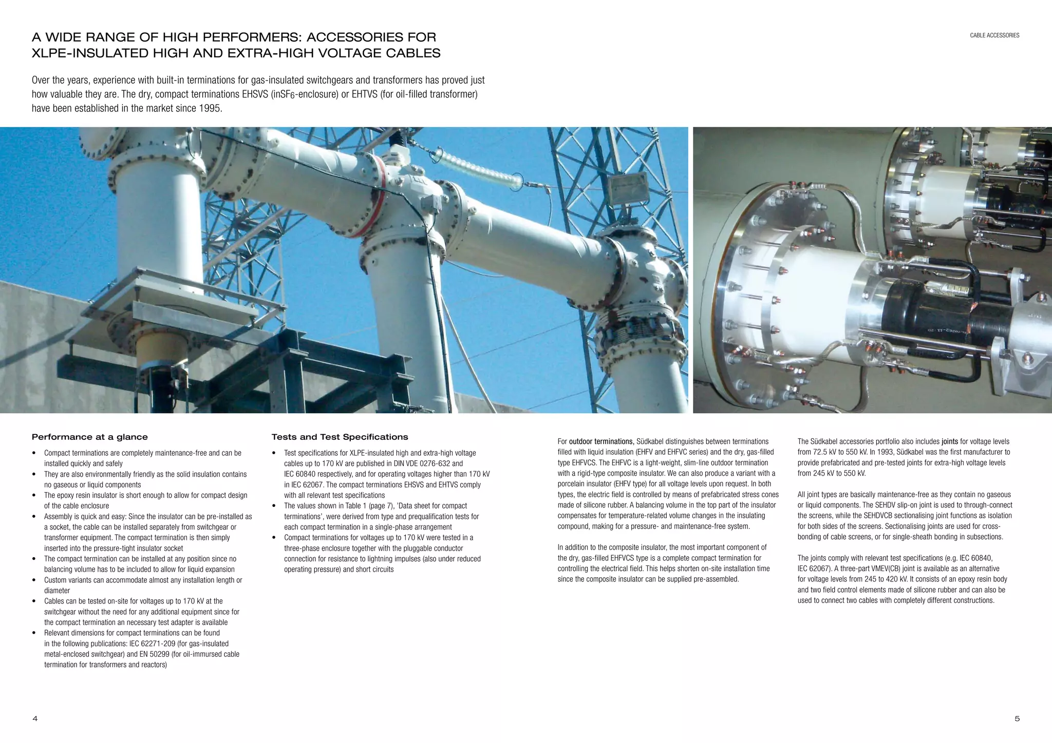
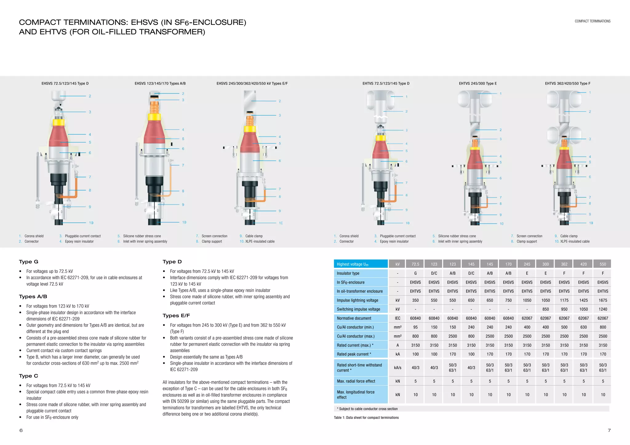
1. The document discusses Südkabel's range of accessories for XLPE-insulated high and extra-high voltage cables, including compact terminations, outdoor terminations, and joints. 2. Südkabel offers a variety of compact termination types for different voltage applications that are maintenance-free, quick to install, and can accommodate different cable designs. 3. Outdoor terminations can be filled with liquid insulation or use dry, gas-filled designs. They meet relevant test standards and are available with composite or porcelain insulators.