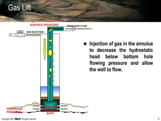
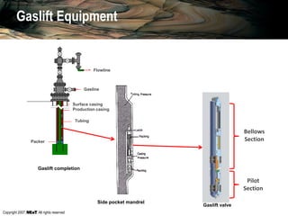
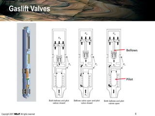
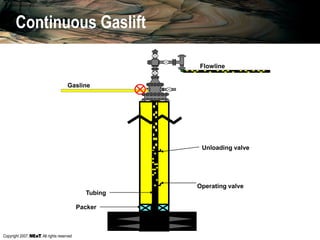
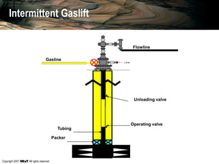
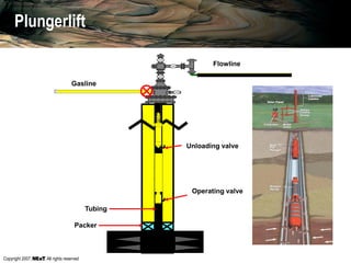
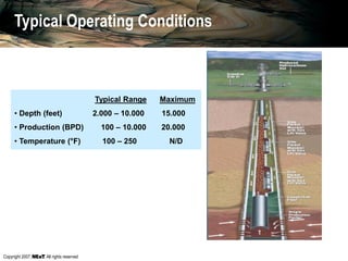
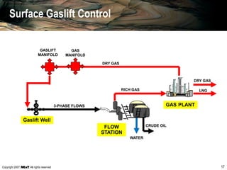
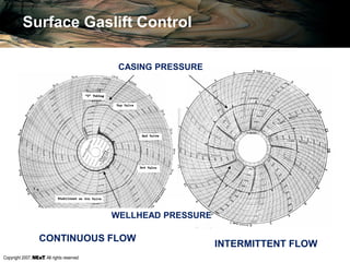
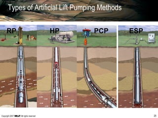
SlideShare a Scribd company logo
Copyright 2007, , All rights reserved
Artificial Lift
Overview of Methods, Equipment and Operation
Copyright 2007, , All rights reserved
.
Pe initial
PRESSUREPwh
DEPTH
Well pressure gradient
Inflow Performance
Pwf initial
Pe actual
Pwf actual
Copyright 2007, , All rights reserved
Gas Lift
Principle
Equipment
Types
Operation
Troubleshooting & Control
Advantages & disadvantages
Copyright 2007, , All rights reserved 4
GAS INJECTION
PRODUCED FLUIDSURFACE PRESSURE
SANDFACE
PRESSURE
BHFP
RESERVOIR
PRESSURE
Gas Lift
 Injection of gas in the annulus
to decrease the hydrostatic
head below bottom hole
flowing pressure and allow
the well to flow.
Copyright 2007, , All rights reserved
Gaslift Equipment
Gasline
Surface casing
Production casing
Tubing
Packer
Flowline
Side pocket mandrel
Bellows
Section
Pilot
Section
Gaslift valve
Gaslift completion
Copyright 2007, , All rights reserved 6
Bellows
Pilot
Gaslift Valves
Copyright 2007, , All rights reserved 7
Types of Gas Lift
 CONTINUOUS FLOW GAS LIFT Steady State Flow;
mechanisms are lowering density, expanding gas and
pushing to surface. P & T remain constant at process plant.
 INTERMITTENT GAS LIFT Batch Production; for low
productivity wells; process problems.
Copyright 2007, , All rights reserved
Continuous Gaslift
Gasline
Flowline
Unloading valve
Operating valve
Tubing
Packer
Copyright 2007, , All rights reserved
Pr
OPENING PRESSURE
.
Val. 1
Val. 2
Val. 3
A
B
C
Pwh
DEPTH
Gaslift Valve Operation
VIDEO
Copyright 2007, , All rights reserved 10
Unloading Gas Lift Valve
 Normally required during unloading phase only
 Open only when annulus and tubing pressures are high
enough to overcome valve set pressure
 Valve closes after transfer to next station
 May be spring or nitrogen charged
Copyright 2007, , All rights reserved 11
Operating Gas Lift Valve
 Typically an ‘orifice’ type Gas lift valve
 always open - allows gas across Passage whenever correct
differential exists
 Gas injection controlled by size and differential across
replaceable choke
 Back-check prevents reverse flow of well fluids from the
production conduit
Copyright 2007, , All rights reserved 12
Gas Injection Rate
DOWNSTREAM PRESSURE (PSI)
SUB-CRITICAL
FLOW
PCASING
PTUBING = 55%
ORIFICE FLOW
GASINJECTIONRATE(MMSCF/D)
Gas passage through the orifice valve
Copyright 2007, , All rights reserved
LIQUID PRODUCTION RATE (QL)
WELLFLOWINGPRESSURE(Pwf)
Well inflow
Pr
TASADEPRODUCCION(QL)
GAS INJECTION RATE(Qgi)
Optimum Economical
Maximum Production
Gaslift injection
Copyright 2007, , All rights reserved
Intermittent Gaslift
Gasline
Flowline
Unloading valve
Operating valve
Tubing
Packer
Copyright 2007, , All rights reserved
Gasline
Flowline
Unloading valve
Operating valve
Tubing
Packer
Plungerlift
Copyright 2007, , All rights reserved
Typical Range Maximum
• Depth (feet) 2.000 – 10.000 15.000
• Production (BPD) 100 – 10.000 20.000
• Temperature (°F) 100 – 250 N/D
Typical Operating Conditions
Copyright 2007, , All rights reserved 17
Gaslift Well
3-PHASE FLOWS
RICH GAS
DRY GAS
CRUDE OIL
DRY GAS
LNG
GAS
MANIFOLD
GAS PLANT
FLOW
STATION
WATER
GASLIFT
MANIFOLD
Surface Gaslift Control
Copyright 2007, , All rights reserved 18
Surface Gaslift Control
GASLIFT MANIFOLD
Manual Flow Control Valve
Actuated Flow Control Valve
Copyright 2007, , All rights reserved
Surface Gaslift Control
INDIRECT METERING OF GAS FLOW TO THE WELL
Copyright 2007, , All rights reserved
Connected to the
production casing valve
to record casing-tubing
annulus pressure.
Connected between the left
wing valve and the choke
box, to record WHP
Surface Gaslift Control
Copyright 2007, , All rights reserved
Surface Gaslift Control
CONTINUOUS FLOW
INTERMITTENT FLOW
CASING PRESSURE
WELLHEAD PRESSURE
Copyright 2007, , All rights reserved 22
Advantages of Gas Lift
 Low initial downhole equipment costs
 Low operational and maintenance cost
 Simplified well completions
 Flexibility - can handle rates from 10 to 50,000 bpd
 Can best handle sand / gas / well deviation
 Intervention relatively less expensive
Copyright 2007, , All rights reserved 23
Disadvantages of Gas Lift
 Must have a source of gas
– Imported from other fields
– Produced gas - may result in start up problems
 Possible high installation cost
– Top sides modifications to existing platforms
– Compressor installation
 Limited by available reservoir pressure and bottom hole
flowing pressure
 Efficiency decreases while BW&S increases
Copyright 2007, , All rights reserved 24
Summary of Gaslift Requirements
 Maximize oil production
 Minimize well intervention (especially in subsea wells)
 Maximize design flexibility without compromising production
 Maximize depth of injection
 Well stability
 Uncertainties in reservoir performance
 Range of reservoir pressures over well life
 Range of watercuts over well life
 Range of gas injection rates
 Valve port sizing and gas passage pressure drops in system
 Valve performance
Copyright 2007, , All rights reserved 25
Types of Artificial Lift Pumping Methods
RP HP PCP ESP
Copyright 2007, , All rights reserved
Principle
Equipment
Operation
Troubleshooting & Control
Advantages and disadvantages
Mechanical Pumping (Sucker Rod Pumps)
Copyright 2007, , All rights reserved
Mechanical Pumping (Sucker Rod Pumps)
Copyright 2007, , All rights reserved 28
Mechanical Pumps
 The first Artificial Lift method to be used and still very popular
 Simple combination of a cylinder, a piston, intake valve and discharge
valve
 Strokes from a few inches to less than 3,000 bopd
 Suitable for viscous oils (+400 cp)
 Main problems:
– low intake pressure
– high discharge pressure
– sand
– corrosion
– scales and deposits
– handling of gases and condensed vapors
Copyright 2007, , All rights reserved 29
Standing valve
Riding valve
Piston
Casing
Tubing
Rod string
Carrier Bar
Counter weight
Crank arm
Gearbox
Head
Elevator
Polished rod
Stuffing Box
Flow line
Gsa line
Sucker Rod Pumping
Copyright 2007, , All rights reserved 30
BARREL
RODS
PISTON
SETTING
BALLS
RIDING
VALVE
FLUID
Sucker Rod Pumping Equipment
Copyright 2007, , All rights reserved
Rod Pumping Troubleshooting and Control
31
Copyright 2007, , All rights reserved 32
DISPLACEMENT
LOAD
UPWARDS STROKE
DOWNWARDS
STROKE
NORMAL FUNCTIONING
ROD
PISTON
STANDIN
G VALVE
FLUID
DOWNWARD MOVEMENT UPWARD MOVEMENT
RIDING
VALVE
FLUID BARREL
Rod Pumping Troubleshooting and Control
Copyright 2007, , All rights reserved 33
Rod Pumping Troubleshooting and Control
Copyright 2007, , All rights reserved
Rod Pumping Typical Problems
34
Displacement
Load
Excessive Pumping Speed Restriction in the Well
Load
When a well is pumped at an
inadequate high speed in the beam’s
motor, it is observed in the chart that
the load decreases when beginning
the upwards piston stroke and
happens a closing in form of circle at
the end of this piston stroke.
Restrictions most of the cases reduce
the volume of fluid entering to the well
and causes in the chart an increasing
upwards load during the piston
stroke, but with excessive
displacement, which indicates little
work of the pump.
Displacement
Copyright 2007, , All rights reserved 35
Rod Pumping Typical Problems
Displacement
Load
Load
Displacement
The fluid blow happens when the
barrel of the pump does not fill
completely during the piston stroke
upwards and it is characterized by
a fast unloading at the end of the
downwards piston stroke.
The gas blow happens when the
pump fills partially with gas,
showing a chart’s shape very
similar to the one of the liquid lock,
but the unloading at the end of the
downwards piston stroke is less
pronounced.
Liquid Blow on the Pump Gas Blow on the Pump
Copyright 2007, , All rights reserved 36
Rod Pumping Typical Problems
Displacement
Load
Load
Displacement
Gas Blockade Full Drained
When the pump fills almost totally
with gas it is called gas blockade
and the chart is recognized
because the load decreases during
the upwards piston stroke and
shows very little work of the pump.
If there is no entrance of fluid to
the pump it generates a chart that
shows very few loads with normal
displacement, but without work of
the pump.
Copyright 2007, , All rights reserved
Electric Submersible Pumps (ESP)
Copyright 2007, , All rights reserved 38
Historical Perspective
 1927 - El Dorado Kansas First
ESP Installation
 Early 1930s - First Horizontal
Pumping Unit
 1960s - First Variable Speed
Applications
 1980s - First ESP Performance
Models
 1990s First Subsea Completed
Applications
Copyright 2007, , All rights reserved
Pwh
PUMP
Pwh
Pwf Pr
Pdn
Pup
ΔP
gas
Pwf
PdnPup
Pressure
Depth
Pup = Suction pressure of pump
Pdn = Unloading pressure of pump
ESP System Functioning
Pr
Copyright 2007, , All rights reserved
LIQUID PRODUCTION RATE, QL
WELLFLOWINGPRESSURE(Pwf)
0
0
ΔP ΔP
Unloading pressure, Pdn
Suction Pressure, Pup
ESP System Functioning
Copyright 2007, , All rights reserved
ESP System Components
Electrical transformer
Well
head
Flare
box
Switch board
Tubing
Drainage valve
Retention valve
Unloading head
Pump
Intake
Protector
Power cable
Motor
Motor base
Casing
Copyright 2007, , All rights reserved 42
ESP Downhole System Components
In wells of high GOR a rotary gas
separator removes the free gas from
the produced fluid through the
casing-tubing annulus, the separator
prevents problems with gas blow and
cavitations, increasing the life of the
equipment.
The motors are bipolar, three-phase
and come full with a very refined
mineral oil to provide dielectric
resistance, lubrication for seals and
thermal conductivity.
The pumps are centrifugal of
several stages. Each stage consists
of a revolving impeller and a fixed
diffuser. The used materials are of
special metallurgy for optimal
operation in corrosive and/or
abrasive environments.
Copyright 2007, , All rights reserved 43
ESP Downhole System Components
 Each "stage" consists of an
impeller and a diffuser. The
impeller takes the fluid and
imparts kinetic energy to it. The
diffuser converts this kinetic
energy into potential energy
(head).
Copyright 2007, , All rights reserved 44
Compliant Mounted Zirconia Radial Bearings
Head and Base Bearing
Stage Bearing
ESP Downhole System Components
Copyright 2007, , All rights reserved 45
ESP Downhole System Components
Typical fluid flow path in a
"mixed flow" stage.
Copyright 2007, , All rights reserved 46
ESP Downhole System Components
The next part of the system is the submergible motor. The motor
is a three phase, squirrel cage, two pole induction design.
PHASE 2
PHASE 3
PHASE 1
The three power phases are "Wye" connected within the motor
itself to establish a "neutral" point.
Copyright 2007, , All rights reserved 47
ESP Downhole System Components
Because of the way the stator is
wound, the three phase power
establishes a two pole magnetic
field within the stator.
The motor is called a squirrel
cage because this is what the
rotor looks like:
Copyright 2007, , All rights reserved 48
ESP Downhole System Components
 The next major component of the ESP system is
the "Protector". The Protector is placed between
the pump and connects the motor shaft to the
pump shaft.
 The Protector also houses the pump's upthrust
and downthrust bearings and provides for
pressure equalization between the outside of the
motor and the inside.
Unloading head
Pump
Intake w/ or wo/
Gas Separator
Protector
Motor
Motor base
Copyright 2007, , All rights reserved 49
ESP Downhole System Components
 Prevents Wellbore Fluids Entering
Motor
 Balances Pressure Between Motor &
Annulus
 Carries Thrust Load of Pump
Shaft bushing
Labyrinth Chamber
Shaft Seals
Thrust Bearing
Filter Screen
Shedder
Elastomer Bag
Protector
Copyright 2007, , All rights reserved 50
ESP Downhole System Components
Between the Protector and the pump is the
pump intake section. This can be either a
standard ported intake or, as shown here,
a centrifugal gas separator to eliminate
free gas from the pumped fluid allowing it
to be produced up the annulus.
Copyright 2007, , All rights reserved 51
ESP Downhole System Components
Another component of the ESP system is the power cable.
This particular cable shows an optional chemical injection line
which can be incorporated within the cable itself.
Copyright 2007, , All rights reserved
OPERATING CONDITIONS:
Typical Range Maximum
• Depth (feet) 1,000 – 10,000 15,000
• Production (BPD) 100 – 20,000 90,000
• Temperature (°F) 100 – 275 400
ADVANTAGES:
• High temperature resistant
• Highly efficient
• Positive displacement
• High liquid rates
DISADVANTAGES:
• High efficiency
• Affected by high GOR
• Little resistant to solids and sand
ESP Operation
Copyright 2007, , All rights reserved 53
The Basic ESP System
Equipment diameters from 3.38” -
(A) series to 11.25” - (P) series
Casing Sizes - 4 1/2” to 13 5/8”
Variable Speed Available
Metallurgies to Suit Applications.
Copyright 2007, , All rights reserved 54
ESP Downhole System Operation
A centrifugal pump produces "constant head". This means that,
regardless of the fluid being pumped, it will be lifted to the same height as
any other fluid for the same flow rate.
Propane Water Oil
Head: The height
to which the pump
will "lift" the fluid
Curves for centrifugal pumps
are normally shown as flow
versus head in feet, meters,
or some other consistent
unit.
Copyright 2007, , All rights reserved 55
ESP Downhole System Operation
From this curves we can determine the head produced, brake
horsepower required and hydraulic efficiency at any flow rate.
R E D
R e v . B
S N 2 6 0 0 6P u m p P- S p . G r . 1 . 0 0
O p t i m u m O p
N o m i n a l H o u
S h a f t D i a m e
S h a f t C r o s s
M i n i m u m C a
6 0 0 - 3 2 0 0
5 . 3 8
0 . 8 7 5
0 . 6 0 1
7 . 0 0 0
b p d
i n c h e s
i n c h e s
i n 2
i n c h e s
S h a f t B r
H o u s i n g
S t a n d
H i g h S
S t a n d
B u t t r e
W e l d e
2 5 6
4 1 0
N / A
6 0 0 0
6 0 0 0
H p
H p
p s i
p s i
p s i
05 0 01 , 0 0 01 , 5 0 02 , 0 0 02 , 5 0 03 , 0 0 03 , 5 0 04 , 0 0 0
R E D
R e v . B
S N 2 6 0 0 6P u m p P- S p . G r . 1 . 0 0
O p t i m u m O p
N o m i n a l H o u
S h a f t D i a m e
S h a f t C r o s s
M i n i m u m C a
6 0 0 - 3 2 0 0
5 . 3 8
0 . 8 7 5
0 . 6 0 1
7 . 0 0 0
b p d
i n c h e s
i n c h e s
i n 2
i n c h e s
S h a f t B r
H o u s i n g
S t a n d
H i g h S
S t a n d
B u t t r e
W e l d e
2 5 6
4 1 0
N / A
6 0 0 0
6 0 0 0
H p
H p
p s i
p s i
p s i
EffHpFeet
ty - Barrels p
1 0 %
2 0 %
3 0 %
4 0 %
5 0 %
6 0 %
B
Q= 2 5
H= 4 6
P= 1 .
E= 6 8
1 0
2 0
3 0
4 0
5 0
6 0
0 . 5 0
1 . 0 0
1 . 5 0
2 . 0 0
2 . 5 0
3 . 0 0
Copyright 2007, , All rights reserved
OPERATION CONDITIONS:
Typical Range Máximum
• Depth (feet) 2.000 – 4.500 6.000
• Volume (BPD) 5 – 2.200 4.500
• Temperature (°F) 75 – 150 225
ADVANTAGES:
• Low investment, operating and maintenence
costs
• High efficiency
• Positive displacement
• Small size surface equipment
DISADVANTAGES:
• Medium to low resistance to high temperatures
• Low resistance to solids
• Incompatibility elastomers - fluid
Progressive Cavity Pumps (PCP)
Copyright 2007, , All rights reserved 57
 Positive displacement pump without
valves
 Delivers a consistent flow
 Stator being stationary attached to
the tubing string
 Rotor rotates driven from the surface
through the rod string and the stator
is attached to the tubing string
 The rotor is a single threaded helix
and the stator is an elastomer lined
double threaded helical cavity.
The Progressive Cavity Pump
Copyright 2007, , All rights reserved
Opportunity of application:
• Deep wells that requires high
torque
• Horizontal and highly deviated
wells
• Rotating gas separator
Downhole Motor PCP
Copyright 2007, , All rights reserved
0
50
100
150
200
250
300
350
400
450
500
0 1000 2000 3000 4000 5000
HEAD (FT. WATER)
CAPACITY(BFPD)
0
2
4
6
8
10
12
14
16
18
HORSEPOWER(HP)
500 RPM
400 RPM
300 RPM
200 RPM
100 RPM
500 RPM
400 RPM
300 RPM
200 RPM
100 RPM
TYPICAL PERFORMANCE OF A PROGRESSIVE CAVITY PUMP
The Progressive Cavity Pump

More Related Content

What's hot

WELL COMPLETION, WELL INTERVENTION/ STIMULATION, AND WORKOVER
WELL COMPLETION, WELL INTERVENTION/ STIMULATION, AND WORKOVERWELL COMPLETION, WELL INTERVENTION/ STIMULATION, AND WORKOVER
WELL COMPLETION, WELL INTERVENTION/ STIMULATION, AND WORKOVER
Andi Anriansyah
 
Artificial Lift Selection Criterion
Artificial Lift Selection CriterionArtificial Lift Selection Criterion
Artificial Lift Selection Criterion
Balaji Chennakrishnan
 
Sucker Rod Pump (SRP)
Sucker Rod Pump (SRP)Sucker Rod Pump (SRP)
Sucker Rod Pump (SRP)
Rakesh Kumar
 
Well test analysis
Well test analysisWell test analysis
Well test analysis
petroleum engineer
 
Electric submersible pump(esp)
Electric submersible pump(esp)Electric submersible pump(esp)
Electric submersible pump(esp)
Win Nyunt Aung
 
Well control and blowout preventer
Well control  and blowout preventerWell control  and blowout preventer
Well control and blowout preventer
Shamim Akram
 
Well completion and stimulation
Well completion and stimulation Well completion and stimulation
Well completion and stimulation
kaleem ullah
 
Progressive Cavity Pump (PCP) Petroleum Production Engineering
Progressive Cavity Pump (PCP) Petroleum Production EngineeringProgressive Cavity Pump (PCP) Petroleum Production Engineering
Progressive Cavity Pump (PCP) Petroleum Production Engineering
Muhammad Hanif
 
Nodal analysis
Nodal analysisNodal analysis
Nodal analysis
Dessy S. Ayu
 
Gas Lift Design: Comparative Study of Continuous and Intermittent Gas Lift (C...
Gas Lift Design: Comparative Study of Continuous and Intermittent Gas Lift (C...Gas Lift Design: Comparative Study of Continuous and Intermittent Gas Lift (C...
Gas Lift Design: Comparative Study of Continuous and Intermittent Gas Lift (C...
Nicodeme Feuwo
 
Horizontal drilling
Horizontal drillingHorizontal drilling
Horizontal drilling
Mubarik Rao
 
Petroleum Production Engineering - Perforation
Petroleum Production Engineering - PerforationPetroleum Production Engineering - Perforation
Petroleum Production Engineering - Perforation
James Craig
 
Well test-procedures-manual
Well test-procedures-manualWell test-procedures-manual
Well test-procedures-manual
Narendra Kumar Dewangan
 
Artificial lift technology
Artificial lift technologyArtificial lift technology
Artificial lift technology
josepazv
 
Well Control and Well Monitoring Systems
Well Control and Well Monitoring SystemsWell Control and Well Monitoring Systems
Well Control and Well Monitoring Systems
AFATous
 
4 1 reservoir-drive_mechanisms
4 1 reservoir-drive_mechanisms4 1 reservoir-drive_mechanisms
4 1 reservoir-drive_mechanisms
Atils
 
Production optimization using gas lift technique
Production optimization using gas lift techniqueProduction optimization using gas lift technique
Production optimization using gas lift technique
Jarjis Mohammed
 
Drill stem test (mtm)
Drill stem test (mtm)Drill stem test (mtm)
Drill stem test (mtm)
majeed talal
 
Casing Seat depth and Basic casing design lecture 4.pdf
Casing Seat depth and Basic casing design  lecture 4.pdfCasing Seat depth and Basic casing design  lecture 4.pdf
Casing Seat depth and Basic casing design lecture 4.pdf
ssuserfec9d8
 
Enhanced oil recovery using steam
Enhanced oil recovery using steamEnhanced oil recovery using steam
Enhanced oil recovery using steam
Noaman Ahmed
 

What's hot (20)

WELL COMPLETION, WELL INTERVENTION/ STIMULATION, AND WORKOVER
WELL COMPLETION, WELL INTERVENTION/ STIMULATION, AND WORKOVERWELL COMPLETION, WELL INTERVENTION/ STIMULATION, AND WORKOVER
WELL COMPLETION, WELL INTERVENTION/ STIMULATION, AND WORKOVER
 
Artificial Lift Selection Criterion
Artificial Lift Selection CriterionArtificial Lift Selection Criterion
Artificial Lift Selection Criterion
 
Sucker Rod Pump (SRP)
Sucker Rod Pump (SRP)Sucker Rod Pump (SRP)
Sucker Rod Pump (SRP)
 
Well test analysis
Well test analysisWell test analysis
Well test analysis
 
Electric submersible pump(esp)
Electric submersible pump(esp)Electric submersible pump(esp)
Electric submersible pump(esp)
 
Well control and blowout preventer
Well control  and blowout preventerWell control  and blowout preventer
Well control and blowout preventer
 
Well completion and stimulation
Well completion and stimulation Well completion and stimulation
Well completion and stimulation
 
Progressive Cavity Pump (PCP) Petroleum Production Engineering
Progressive Cavity Pump (PCP) Petroleum Production EngineeringProgressive Cavity Pump (PCP) Petroleum Production Engineering
Progressive Cavity Pump (PCP) Petroleum Production Engineering
 
Nodal analysis
Nodal analysisNodal analysis
Nodal analysis
 
Gas Lift Design: Comparative Study of Continuous and Intermittent Gas Lift (C...
Gas Lift Design: Comparative Study of Continuous and Intermittent Gas Lift (C...Gas Lift Design: Comparative Study of Continuous and Intermittent Gas Lift (C...
Gas Lift Design: Comparative Study of Continuous and Intermittent Gas Lift (C...
 
Horizontal drilling
Horizontal drillingHorizontal drilling
Horizontal drilling
 
Petroleum Production Engineering - Perforation
Petroleum Production Engineering - PerforationPetroleum Production Engineering - Perforation
Petroleum Production Engineering - Perforation
 
Well test-procedures-manual
Well test-procedures-manualWell test-procedures-manual
Well test-procedures-manual
 
Artificial lift technology
Artificial lift technologyArtificial lift technology
Artificial lift technology
 
Well Control and Well Monitoring Systems
Well Control and Well Monitoring SystemsWell Control and Well Monitoring Systems
Well Control and Well Monitoring Systems
 
4 1 reservoir-drive_mechanisms
4 1 reservoir-drive_mechanisms4 1 reservoir-drive_mechanisms
4 1 reservoir-drive_mechanisms
 
Production optimization using gas lift technique
Production optimization using gas lift techniqueProduction optimization using gas lift technique
Production optimization using gas lift technique
 
Drill stem test (mtm)
Drill stem test (mtm)Drill stem test (mtm)
Drill stem test (mtm)
 
Casing Seat depth and Basic casing design lecture 4.pdf
Casing Seat depth and Basic casing design  lecture 4.pdfCasing Seat depth and Basic casing design  lecture 4.pdf
Casing Seat depth and Basic casing design lecture 4.pdf
 
Enhanced oil recovery using steam
Enhanced oil recovery using steamEnhanced oil recovery using steam
Enhanced oil recovery using steam
 

Similar to 13 artificial-lift

fdocuments.net_artificial-lift-564cd63eb3ce7.pdf
fdocuments.net_artificial-lift-564cd63eb3ce7.pdffdocuments.net_artificial-lift-564cd63eb3ce7.pdf
fdocuments.net_artificial-lift-564cd63eb3ce7.pdf
Moujahed Farés
 
3_Artificial_lift_systems.ppt
3_Artificial_lift_systems.ppt3_Artificial_lift_systems.ppt
3_Artificial_lift_systems.ppt
athifaputricaesar
 
Gas Turbine Training Power Point -Sample
Gas Turbine Training Power Point -SampleGas Turbine Training Power Point -Sample
Gas Turbine Training Power Point -Sample
Ali Rafiei
 
Gas-Lift-Production.ppt
Gas-Lift-Production.pptGas-Lift-Production.ppt
Gas-Lift-Production.ppt
TemitopeBello6
 
Multiphase Advanced Pumping System for Artificial Lift MAPS-AL
Multiphase Advanced Pumping System for Artificial Lift MAPS-ALMultiphase Advanced Pumping System for Artificial Lift MAPS-AL
Multiphase Advanced Pumping System for Artificial Lift MAPS-AL
YuriFairuzov
 
Compressor
CompressorCompressor
Compressor
ARUN VISHNU
 
Regenerative Turbine Chemical Process Pumps
Regenerative Turbine Chemical Process PumpsRegenerative Turbine Chemical Process Pumps
Regenerative Turbine Chemical Process Pumps
Mountain States Engineering and Controls
 
srp-161203072620.pptx
srp-161203072620.pptxsrp-161203072620.pptx
srp-161203072620.pptx
MuammerAlakary
 
1.1 Introduction to Art.lift.ppt
1.1  Introduction  to Art.lift.ppt1.1  Introduction  to Art.lift.ppt
1.1 Introduction to Art.lift.ppt
MichaelJackson115537
 
Prod. II Lectures.pptx
Prod. II Lectures.pptxProd. II Lectures.pptx
Prod. II Lectures.pptx
IbrahimHrari
 
SPE 172686 final
SPE 172686 finalSPE 172686 final
SPE 172686 final
Soham Agarwal
 
APT Hydraulic Pump Investor Pres Saxon Tech
APT Hydraulic Pump Investor Pres Saxon TechAPT Hydraulic Pump Investor Pres Saxon Tech
APT Hydraulic Pump Investor Pres Saxon Tech
mvb2597
 
The Piston Less Pump Working Explained in PPT
The Piston Less Pump Working Explained  in PPTThe Piston Less Pump Working Explained  in PPT
The Piston Less Pump Working Explained in PPT
lingarajrsat
 
2020-6_TechPres_Ball.pdf
2020-6_TechPres_Ball.pdf2020-6_TechPres_Ball.pdf
2020-6_TechPres_Ball.pdf
tuanvuthanh4
 
Steam turbine
Steam turbineSteam turbine
Steam turbine
Nathan
 
2018pumster company introduction
2018pumster company introduction2018pumster company introduction
2018pumster company introduction
pumster
 
Y2 PUMPS TRAINING FOR OIL AND GAS OPERATION.ppt
Y2 PUMPS TRAINING FOR OIL AND GAS OPERATION.pptY2 PUMPS TRAINING FOR OIL AND GAS OPERATION.ppt
Y2 PUMPS TRAINING FOR OIL AND GAS OPERATION.ppt
ssuser2ec709
 
2018 pumster english catalog
2018 pumster english catalog2018 pumster english catalog
2018 pumster english catalog
pumster
 
1666 CASE IH Axial - flow combine parts catalog
1666 CASE IH Axial - flow combine parts catalog1666 CASE IH Axial - flow combine parts catalog
1666 CASE IH Axial - flow combine parts catalog
PartCatalogs Net
 
TangentFlow Technical Paper FINAL 221015 OCT 22 2015
TangentFlow Technical Paper FINAL 221015 OCT 22 2015TangentFlow Technical Paper FINAL 221015 OCT 22 2015
TangentFlow Technical Paper FINAL 221015 OCT 22 2015
Corbin Coyes
 

Similar to 13 artificial-lift (20)

fdocuments.net_artificial-lift-564cd63eb3ce7.pdf
fdocuments.net_artificial-lift-564cd63eb3ce7.pdffdocuments.net_artificial-lift-564cd63eb3ce7.pdf
fdocuments.net_artificial-lift-564cd63eb3ce7.pdf
 
3_Artificial_lift_systems.ppt
3_Artificial_lift_systems.ppt3_Artificial_lift_systems.ppt
3_Artificial_lift_systems.ppt
 
Gas Turbine Training Power Point -Sample
Gas Turbine Training Power Point -SampleGas Turbine Training Power Point -Sample
Gas Turbine Training Power Point -Sample
 
Gas-Lift-Production.ppt
Gas-Lift-Production.pptGas-Lift-Production.ppt
Gas-Lift-Production.ppt
 
Multiphase Advanced Pumping System for Artificial Lift MAPS-AL
Multiphase Advanced Pumping System for Artificial Lift MAPS-ALMultiphase Advanced Pumping System for Artificial Lift MAPS-AL
Multiphase Advanced Pumping System for Artificial Lift MAPS-AL
 
Compressor
CompressorCompressor
Compressor
 
Regenerative Turbine Chemical Process Pumps
Regenerative Turbine Chemical Process PumpsRegenerative Turbine Chemical Process Pumps
Regenerative Turbine Chemical Process Pumps
 
srp-161203072620.pptx
srp-161203072620.pptxsrp-161203072620.pptx
srp-161203072620.pptx
 
1.1 Introduction to Art.lift.ppt
1.1  Introduction  to Art.lift.ppt1.1  Introduction  to Art.lift.ppt
1.1 Introduction to Art.lift.ppt
 
Prod. II Lectures.pptx
Prod. II Lectures.pptxProd. II Lectures.pptx
Prod. II Lectures.pptx
 
SPE 172686 final
SPE 172686 finalSPE 172686 final
SPE 172686 final
 
APT Hydraulic Pump Investor Pres Saxon Tech
APT Hydraulic Pump Investor Pres Saxon TechAPT Hydraulic Pump Investor Pres Saxon Tech
APT Hydraulic Pump Investor Pres Saxon Tech
 
The Piston Less Pump Working Explained in PPT
The Piston Less Pump Working Explained  in PPTThe Piston Less Pump Working Explained  in PPT
The Piston Less Pump Working Explained in PPT
 
2020-6_TechPres_Ball.pdf
2020-6_TechPres_Ball.pdf2020-6_TechPres_Ball.pdf
2020-6_TechPres_Ball.pdf
 
Steam turbine
Steam turbineSteam turbine
Steam turbine
 
2018pumster company introduction
2018pumster company introduction2018pumster company introduction
2018pumster company introduction
 
Y2 PUMPS TRAINING FOR OIL AND GAS OPERATION.ppt
Y2 PUMPS TRAINING FOR OIL AND GAS OPERATION.pptY2 PUMPS TRAINING FOR OIL AND GAS OPERATION.ppt
Y2 PUMPS TRAINING FOR OIL AND GAS OPERATION.ppt
 
2018 pumster english catalog
2018 pumster english catalog2018 pumster english catalog
2018 pumster english catalog
 
1666 CASE IH Axial - flow combine parts catalog
1666 CASE IH Axial - flow combine parts catalog1666 CASE IH Axial - flow combine parts catalog
1666 CASE IH Axial - flow combine parts catalog
 
TangentFlow Technical Paper FINAL 221015 OCT 22 2015
TangentFlow Technical Paper FINAL 221015 OCT 22 2015TangentFlow Technical Paper FINAL 221015 OCT 22 2015
TangentFlow Technical Paper FINAL 221015 OCT 22 2015
 

13 artificial-lift

  • 1. Copyright 2007, , All rights reserved Artificial Lift Overview of Methods, Equipment and Operation
  • 2. Copyright 2007, , All rights reserved . Pe initial PRESSUREPwh DEPTH Well pressure gradient Inflow Performance Pwf initial Pe actual Pwf actual
  • 3. Copyright 2007, , All rights reserved Gas Lift Principle Equipment Types Operation Troubleshooting & Control Advantages & disadvantages
  • 4. Copyright 2007, , All rights reserved 4 GAS INJECTION PRODUCED FLUIDSURFACE PRESSURE SANDFACE PRESSURE BHFP RESERVOIR PRESSURE Gas Lift  Injection of gas in the annulus to decrease the hydrostatic head below bottom hole flowing pressure and allow the well to flow.
  • 5. Copyright 2007, , All rights reserved Gaslift Equipment Gasline Surface casing Production casing Tubing Packer Flowline Side pocket mandrel Bellows Section Pilot Section Gaslift valve Gaslift completion
  • 6. Copyright 2007, , All rights reserved 6 Bellows Pilot Gaslift Valves
  • 7. Copyright 2007, , All rights reserved 7 Types of Gas Lift  CONTINUOUS FLOW GAS LIFT Steady State Flow; mechanisms are lowering density, expanding gas and pushing to surface. P & T remain constant at process plant.  INTERMITTENT GAS LIFT Batch Production; for low productivity wells; process problems.
  • 8. Copyright 2007, , All rights reserved Continuous Gaslift Gasline Flowline Unloading valve Operating valve Tubing Packer
  • 9. Copyright 2007, , All rights reserved Pr OPENING PRESSURE . Val. 1 Val. 2 Val. 3 A B C Pwh DEPTH Gaslift Valve Operation VIDEO
  • 10. Copyright 2007, , All rights reserved 10 Unloading Gas Lift Valve  Normally required during unloading phase only  Open only when annulus and tubing pressures are high enough to overcome valve set pressure  Valve closes after transfer to next station  May be spring or nitrogen charged
  • 11. Copyright 2007, , All rights reserved 11 Operating Gas Lift Valve  Typically an ‘orifice’ type Gas lift valve  always open - allows gas across Passage whenever correct differential exists  Gas injection controlled by size and differential across replaceable choke  Back-check prevents reverse flow of well fluids from the production conduit
  • 12. Copyright 2007, , All rights reserved 12 Gas Injection Rate DOWNSTREAM PRESSURE (PSI) SUB-CRITICAL FLOW PCASING PTUBING = 55% ORIFICE FLOW GASINJECTIONRATE(MMSCF/D) Gas passage through the orifice valve
  • 13. Copyright 2007, , All rights reserved LIQUID PRODUCTION RATE (QL) WELLFLOWINGPRESSURE(Pwf) Well inflow Pr TASADEPRODUCCION(QL) GAS INJECTION RATE(Qgi) Optimum Economical Maximum Production Gaslift injection
  • 14. Copyright 2007, , All rights reserved Intermittent Gaslift Gasline Flowline Unloading valve Operating valve Tubing Packer
  • 15. Copyright 2007, , All rights reserved Gasline Flowline Unloading valve Operating valve Tubing Packer Plungerlift
  • 16. Copyright 2007, , All rights reserved Typical Range Maximum • Depth (feet) 2.000 – 10.000 15.000 • Production (BPD) 100 – 10.000 20.000 • Temperature (°F) 100 – 250 N/D Typical Operating Conditions
  • 17. Copyright 2007, , All rights reserved 17 Gaslift Well 3-PHASE FLOWS RICH GAS DRY GAS CRUDE OIL DRY GAS LNG GAS MANIFOLD GAS PLANT FLOW STATION WATER GASLIFT MANIFOLD Surface Gaslift Control
  • 18. Copyright 2007, , All rights reserved 18 Surface Gaslift Control GASLIFT MANIFOLD Manual Flow Control Valve Actuated Flow Control Valve
  • 19. Copyright 2007, , All rights reserved Surface Gaslift Control INDIRECT METERING OF GAS FLOW TO THE WELL
  • 20. Copyright 2007, , All rights reserved Connected to the production casing valve to record casing-tubing annulus pressure. Connected between the left wing valve and the choke box, to record WHP Surface Gaslift Control
  • 21. Copyright 2007, , All rights reserved Surface Gaslift Control CONTINUOUS FLOW INTERMITTENT FLOW CASING PRESSURE WELLHEAD PRESSURE
  • 22. Copyright 2007, , All rights reserved 22 Advantages of Gas Lift  Low initial downhole equipment costs  Low operational and maintenance cost  Simplified well completions  Flexibility - can handle rates from 10 to 50,000 bpd  Can best handle sand / gas / well deviation  Intervention relatively less expensive
  • 23. Copyright 2007, , All rights reserved 23 Disadvantages of Gas Lift  Must have a source of gas – Imported from other fields – Produced gas - may result in start up problems  Possible high installation cost – Top sides modifications to existing platforms – Compressor installation  Limited by available reservoir pressure and bottom hole flowing pressure  Efficiency decreases while BW&S increases
  • 24. Copyright 2007, , All rights reserved 24 Summary of Gaslift Requirements  Maximize oil production  Minimize well intervention (especially in subsea wells)  Maximize design flexibility without compromising production  Maximize depth of injection  Well stability  Uncertainties in reservoir performance  Range of reservoir pressures over well life  Range of watercuts over well life  Range of gas injection rates  Valve port sizing and gas passage pressure drops in system  Valve performance
  • 25. Copyright 2007, , All rights reserved 25 Types of Artificial Lift Pumping Methods RP HP PCP ESP
  • 26. Copyright 2007, , All rights reserved Principle Equipment Operation Troubleshooting & Control Advantages and disadvantages Mechanical Pumping (Sucker Rod Pumps)
  • 27. Copyright 2007, , All rights reserved Mechanical Pumping (Sucker Rod Pumps)
  • 28. Copyright 2007, , All rights reserved 28 Mechanical Pumps  The first Artificial Lift method to be used and still very popular  Simple combination of a cylinder, a piston, intake valve and discharge valve  Strokes from a few inches to less than 3,000 bopd  Suitable for viscous oils (+400 cp)  Main problems: – low intake pressure – high discharge pressure – sand – corrosion – scales and deposits – handling of gases and condensed vapors
  • 29. Copyright 2007, , All rights reserved 29 Standing valve Riding valve Piston Casing Tubing Rod string Carrier Bar Counter weight Crank arm Gearbox Head Elevator Polished rod Stuffing Box Flow line Gsa line Sucker Rod Pumping
  • 30. Copyright 2007, , All rights reserved 30 BARREL RODS PISTON SETTING BALLS RIDING VALVE FLUID Sucker Rod Pumping Equipment
  • 31. Copyright 2007, , All rights reserved Rod Pumping Troubleshooting and Control 31
  • 32. Copyright 2007, , All rights reserved 32 DISPLACEMENT LOAD UPWARDS STROKE DOWNWARDS STROKE NORMAL FUNCTIONING ROD PISTON STANDIN G VALVE FLUID DOWNWARD MOVEMENT UPWARD MOVEMENT RIDING VALVE FLUID BARREL Rod Pumping Troubleshooting and Control
  • 33. Copyright 2007, , All rights reserved 33 Rod Pumping Troubleshooting and Control
  • 34. Copyright 2007, , All rights reserved Rod Pumping Typical Problems 34 Displacement Load Excessive Pumping Speed Restriction in the Well Load When a well is pumped at an inadequate high speed in the beam’s motor, it is observed in the chart that the load decreases when beginning the upwards piston stroke and happens a closing in form of circle at the end of this piston stroke. Restrictions most of the cases reduce the volume of fluid entering to the well and causes in the chart an increasing upwards load during the piston stroke, but with excessive displacement, which indicates little work of the pump. Displacement
  • 35. Copyright 2007, , All rights reserved 35 Rod Pumping Typical Problems Displacement Load Load Displacement The fluid blow happens when the barrel of the pump does not fill completely during the piston stroke upwards and it is characterized by a fast unloading at the end of the downwards piston stroke. The gas blow happens when the pump fills partially with gas, showing a chart’s shape very similar to the one of the liquid lock, but the unloading at the end of the downwards piston stroke is less pronounced. Liquid Blow on the Pump Gas Blow on the Pump
  • 36. Copyright 2007, , All rights reserved 36 Rod Pumping Typical Problems Displacement Load Load Displacement Gas Blockade Full Drained When the pump fills almost totally with gas it is called gas blockade and the chart is recognized because the load decreases during the upwards piston stroke and shows very little work of the pump. If there is no entrance of fluid to the pump it generates a chart that shows very few loads with normal displacement, but without work of the pump.
  • 37. Copyright 2007, , All rights reserved Electric Submersible Pumps (ESP)
  • 38. Copyright 2007, , All rights reserved 38 Historical Perspective  1927 - El Dorado Kansas First ESP Installation  Early 1930s - First Horizontal Pumping Unit  1960s - First Variable Speed Applications  1980s - First ESP Performance Models  1990s First Subsea Completed Applications
  • 39. Copyright 2007, , All rights reserved Pwh PUMP Pwh Pwf Pr Pdn Pup ΔP gas Pwf PdnPup Pressure Depth Pup = Suction pressure of pump Pdn = Unloading pressure of pump ESP System Functioning Pr
  • 40. Copyright 2007, , All rights reserved LIQUID PRODUCTION RATE, QL WELLFLOWINGPRESSURE(Pwf) 0 0 ΔP ΔP Unloading pressure, Pdn Suction Pressure, Pup ESP System Functioning
  • 41. Copyright 2007, , All rights reserved ESP System Components Electrical transformer Well head Flare box Switch board Tubing Drainage valve Retention valve Unloading head Pump Intake Protector Power cable Motor Motor base Casing
  • 42. Copyright 2007, , All rights reserved 42 ESP Downhole System Components In wells of high GOR a rotary gas separator removes the free gas from the produced fluid through the casing-tubing annulus, the separator prevents problems with gas blow and cavitations, increasing the life of the equipment. The motors are bipolar, three-phase and come full with a very refined mineral oil to provide dielectric resistance, lubrication for seals and thermal conductivity. The pumps are centrifugal of several stages. Each stage consists of a revolving impeller and a fixed diffuser. The used materials are of special metallurgy for optimal operation in corrosive and/or abrasive environments.
  • 43. Copyright 2007, , All rights reserved 43 ESP Downhole System Components  Each "stage" consists of an impeller and a diffuser. The impeller takes the fluid and imparts kinetic energy to it. The diffuser converts this kinetic energy into potential energy (head).
  • 44. Copyright 2007, , All rights reserved 44 Compliant Mounted Zirconia Radial Bearings Head and Base Bearing Stage Bearing ESP Downhole System Components
  • 45. Copyright 2007, , All rights reserved 45 ESP Downhole System Components Typical fluid flow path in a "mixed flow" stage.
  • 46. Copyright 2007, , All rights reserved 46 ESP Downhole System Components The next part of the system is the submergible motor. The motor is a three phase, squirrel cage, two pole induction design. PHASE 2 PHASE 3 PHASE 1 The three power phases are "Wye" connected within the motor itself to establish a "neutral" point.
  • 47. Copyright 2007, , All rights reserved 47 ESP Downhole System Components Because of the way the stator is wound, the three phase power establishes a two pole magnetic field within the stator. The motor is called a squirrel cage because this is what the rotor looks like:
  • 48. Copyright 2007, , All rights reserved 48 ESP Downhole System Components  The next major component of the ESP system is the "Protector". The Protector is placed between the pump and connects the motor shaft to the pump shaft.  The Protector also houses the pump's upthrust and downthrust bearings and provides for pressure equalization between the outside of the motor and the inside. Unloading head Pump Intake w/ or wo/ Gas Separator Protector Motor Motor base
  • 49. Copyright 2007, , All rights reserved 49 ESP Downhole System Components  Prevents Wellbore Fluids Entering Motor  Balances Pressure Between Motor & Annulus  Carries Thrust Load of Pump Shaft bushing Labyrinth Chamber Shaft Seals Thrust Bearing Filter Screen Shedder Elastomer Bag Protector
  • 50. Copyright 2007, , All rights reserved 50 ESP Downhole System Components Between the Protector and the pump is the pump intake section. This can be either a standard ported intake or, as shown here, a centrifugal gas separator to eliminate free gas from the pumped fluid allowing it to be produced up the annulus.
  • 51. Copyright 2007, , All rights reserved 51 ESP Downhole System Components Another component of the ESP system is the power cable. This particular cable shows an optional chemical injection line which can be incorporated within the cable itself.
  • 52. Copyright 2007, , All rights reserved OPERATING CONDITIONS: Typical Range Maximum • Depth (feet) 1,000 – 10,000 15,000 • Production (BPD) 100 – 20,000 90,000 • Temperature (°F) 100 – 275 400 ADVANTAGES: • High temperature resistant • Highly efficient • Positive displacement • High liquid rates DISADVANTAGES: • High efficiency • Affected by high GOR • Little resistant to solids and sand ESP Operation
  • 53. Copyright 2007, , All rights reserved 53 The Basic ESP System Equipment diameters from 3.38” - (A) series to 11.25” - (P) series Casing Sizes - 4 1/2” to 13 5/8” Variable Speed Available Metallurgies to Suit Applications.
  • 54. Copyright 2007, , All rights reserved 54 ESP Downhole System Operation A centrifugal pump produces "constant head". This means that, regardless of the fluid being pumped, it will be lifted to the same height as any other fluid for the same flow rate. Propane Water Oil Head: The height to which the pump will "lift" the fluid Curves for centrifugal pumps are normally shown as flow versus head in feet, meters, or some other consistent unit.
  • 55. Copyright 2007, , All rights reserved 55 ESP Downhole System Operation From this curves we can determine the head produced, brake horsepower required and hydraulic efficiency at any flow rate. R E D R e v . B S N 2 6 0 0 6P u m p P- S p . G r . 1 . 0 0 O p t i m u m O p N o m i n a l H o u S h a f t D i a m e S h a f t C r o s s M i n i m u m C a 6 0 0 - 3 2 0 0 5 . 3 8 0 . 8 7 5 0 . 6 0 1 7 . 0 0 0 b p d i n c h e s i n c h e s i n 2 i n c h e s S h a f t B r H o u s i n g S t a n d H i g h S S t a n d B u t t r e W e l d e 2 5 6 4 1 0 N / A 6 0 0 0 6 0 0 0 H p H p p s i p s i p s i 05 0 01 , 0 0 01 , 5 0 02 , 0 0 02 , 5 0 03 , 0 0 03 , 5 0 04 , 0 0 0 R E D R e v . B S N 2 6 0 0 6P u m p P- S p . G r . 1 . 0 0 O p t i m u m O p N o m i n a l H o u S h a f t D i a m e S h a f t C r o s s M i n i m u m C a 6 0 0 - 3 2 0 0 5 . 3 8 0 . 8 7 5 0 . 6 0 1 7 . 0 0 0 b p d i n c h e s i n c h e s i n 2 i n c h e s S h a f t B r H o u s i n g S t a n d H i g h S S t a n d B u t t r e W e l d e 2 5 6 4 1 0 N / A 6 0 0 0 6 0 0 0 H p H p p s i p s i p s i EffHpFeet ty - Barrels p 1 0 % 2 0 % 3 0 % 4 0 % 5 0 % 6 0 % B Q= 2 5 H= 4 6 P= 1 . E= 6 8 1 0 2 0 3 0 4 0 5 0 6 0 0 . 5 0 1 . 0 0 1 . 5 0 2 . 0 0 2 . 5 0 3 . 0 0
  • 56. Copyright 2007, , All rights reserved OPERATION CONDITIONS: Typical Range Máximum • Depth (feet) 2.000 – 4.500 6.000 • Volume (BPD) 5 – 2.200 4.500 • Temperature (°F) 75 – 150 225 ADVANTAGES: • Low investment, operating and maintenence costs • High efficiency • Positive displacement • Small size surface equipment DISADVANTAGES: • Medium to low resistance to high temperatures • Low resistance to solids • Incompatibility elastomers - fluid Progressive Cavity Pumps (PCP)
  • 57. Copyright 2007, , All rights reserved 57  Positive displacement pump without valves  Delivers a consistent flow  Stator being stationary attached to the tubing string  Rotor rotates driven from the surface through the rod string and the stator is attached to the tubing string  The rotor is a single threaded helix and the stator is an elastomer lined double threaded helical cavity. The Progressive Cavity Pump
  • 58. Copyright 2007, , All rights reserved Opportunity of application: • Deep wells that requires high torque • Horizontal and highly deviated wells • Rotating gas separator Downhole Motor PCP
  • 59. Copyright 2007, , All rights reserved 0 50 100 150 200 250 300 350 400 450 500 0 1000 2000 3000 4000 5000 HEAD (FT. WATER) CAPACITY(BFPD) 0 2 4 6 8 10 12 14 16 18 HORSEPOWER(HP) 500 RPM 400 RPM 300 RPM 200 RPM 100 RPM 500 RPM 400 RPM 300 RPM 200 RPM 100 RPM TYPICAL PERFORMANCE OF A PROGRESSIVE CAVITY PUMP The Progressive Cavity Pump