Downloaded 40 times

![DESIGN & ANALYSIS OF PRECAST DRIVEN PILE (450mm X 450mm SQ)
PROJECT TITLE: 2X660MW MAITREE SUPER THERMAL POWER PROJECT.
LOCATION:RAMPAL, BAGERHAT, BANGLADESH.
PAGE 2 OF 4
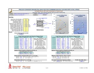
1.0 CHECK FOR DRIVING STRESS
Formula for use with Hydraulic Hammer:
Ru= [12efEn/ (s+0.5(C1+C2+C3)] x [(Wr+e Wp) / (Wr+Wp)] --------- (I)
Where,
Ru = ultimate carrying capacity of pile
(considered as ultimate resistance to
driving)
Wr= weight of falling mass, lb
En=Rated energy per blow, ft-lb
ef= hammer efficiency =100 percent for
hydraulic hammer.
Wp= weight of pile
L = length of pile, inch.
e = coefficient of restitution
s = set value
C1= temporary compression allowance
for pile head and cap.
C2= temporary compression of pile, inch.
= Ru L/ AE
C3= temporary compression allowance
for quake of ground
A= average cross section of pile, Sq.inch
E= modulus of elasticity for pile
material=57000√ f’c
Using the above equation,
Developed Stress on Concrete during driving = = 19.50 Mpa < 40 Mpa
[REFERENCE: APPENDIX-A]
HENCE SAFE FOR CONCRETE COMPRESSIVE STRENGTH AT DRIVING.
2.0 CHECK FOR LIFTING & PITCHING STRESS
Total dead weight of pile, W ' =[0.45x0.45x25x15] kN= 75.9375kN
Factored Dead Weight of Pile, W =1.4 x 81= 106.3125 kN [ACI-318-14: TABLE 5.3.1]
2.0.1. DURING PITCHING
For one point pitching at 3L/10, maximum developed moment = WL/22 ………… (II)
=106.3125 X 15/22 = 82.47 kN-m
Maximum Developed Moment, Mu=82.47 kN-m
2.0.1.1 MOMENT CAPACITY OF REINFORCED CONCRETE SECTION
Using 4 Nos 32mm-φ bar,
Moment Capacity of the section, Mc = 247.10 kN-m > 82.47 kN-m.
[APPENDIX-B –ANALYSIS ON SECTION CAPACITY.]](https://image.slidesharecdn.com/precastdrivenpile450x450-180415203910/85/Precast-driven-pile-450-x450-3-320.jpg)
![DESIGN & ANALYSIS OF PRECAST DRIVEN PILE (450mm X 450mm SQ)
PROJECT TITLE: 2X660MW MAITREE SUPER THERMAL POWER PROJECT.
LOCATION:RAMPAL, BAGERHAT, BANGLADESH.
PAGE 3 OF 4
HENCE SAFE FOR ONE POINT PITCHING (AT 0.3 L).
2.0.2 DURING LIFTING
For two point lifting at L/5, maximum developed moment = WL/40 < WL/22
HENCE SAFE FOR TWO-POINT LIFTING (AT 0.2 L).
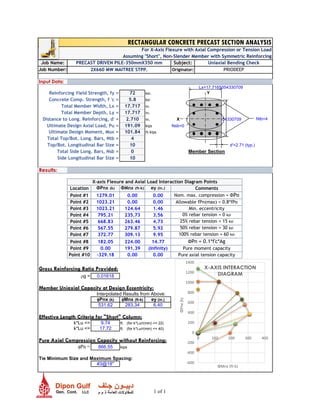
3.0 CHECK FOR AXIAL STRESS
According to ACI-318-14-10.3.6 & ACI-318-14-22.4.2,
Axial Capacity of Pile with Lateral Ties:
φPn = 0.80 φ [0.85 fC’(Ag-Ast) + fyAst]
φPn = 0.80 X 0.65 X [0.85 X40 X (202500-3216.99) +500 X 3216.99)]
= 4359.741 kN = 435.9 TON
4.0 CHECK FOR UPLIFT CAPACITY
According to ACI 543-R-4.3.3.1, the uplift capacity of the section can be determined from the
following equation,
Pup =0.5 x fy x Ast
Pup =0.5 x 500 x 3216.99=804.247 kN. = 80.43 Ton
5.0 CHECK FOR LATERAL CAPACITY
Here Vu=70 kN≈ 15.75 Kip (Design Maximum Lateral Load at Fixed Head Condition)
f’c=40 MPa=5800 psi
fy=500 MPa=72000 psi
According to ACI-318-14, lateral capacity of the section,
φVc= φ2√ f’c bw d
= (0.75×2√5800×17.71×15.12)/1000 [φ = 0.75 (ACI-318-14-21.2.1)]
=30.59 Kips>Vu
Smax =3 inches (ACI 318-02, Section 7.10.4.3)
Smin =1 inches (ACI 318-02, Section 7.10.4.3)
HENCE, PROVIDE 10 mm DIA BAR @ 75 mm C/C.](https://image.slidesharecdn.com/precastdrivenpile450x450-180415203910/85/Precast-driven-pile-450-x450-4-320.jpg)
![DESIGN & ANALYSIS OF PRECAST DRIVEN PILE (450mm X 450mm SQ)
PROJECT TITLE: 2X660MW MAITREE SUPER THERMAL POWER PROJECT.
LOCATION:RAMPAL, BAGERHAT, BANGLADESH.
PAGE 4 OF 4
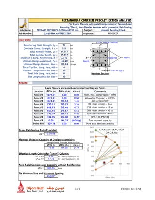
6.0 EVALUATION OF POINT OF FIXITY OF PILE
Considering Clayey Strata:
1.4 [Ep lw / Es] 0.25
= 1.4 x [4340.59 x 0.399/2.08]0.25
= 7.52 ft = 2.3m
Where,
Es = soil modulus for clays=2.08 [Ref: Table: C10.4.6.3-1, AASHTO- 2010]
Hence critical value of point of fixity at 2.30 m from top of pile has been
considered.
Maximum Bending Moment due to Lateral Load,
Mf = 138.00 kN-m.
RECOMMENDATIONS
From the above moment analysis, it is visible that, during 1-point pitching (at 0.3L
distance) the developed moment along pile, is higher than the moment developed during 2-
point lifting and shifting (at 0.2 L distance).
Hence although during lifting, the developed moment is less than the moment
developed during pitching, it is recommended to consider the developed moment during
pitching as the ultimate developed moment for safe lifting transferring, pitching and driving
of the pile.
2.30m
70 kN
0.2L 0.2L
Lifting & shifting technique Pitching technique
23.70m](https://image.slidesharecdn.com/precastdrivenpile450x450-180415203910/85/Precast-driven-pile-450-x450-5-320.jpg)
![www.priodeep.weebly.com
GRADE (MPA) GRADE (psi)
m m
PILE SIZE 0.45 0.45
LENGTH 11 m 500 72519
10000.00 lb
59000.00 lb-ft
100.00 %
12519.11
432.96 inches.
0.25 inches.
0.10
3.179E-07 X Ru
0.10
313.71 Sq.inches
4341559.45 psi
8.472E-08 X Ru
2
+ 0.35 = 0
= lbs
= N
19.50 MPa HENCE OK!!
3948147.426
Stress on concrete during driving(Ru/A) =
E= modulus of elasticity for pile material=57000√ f’c
So, placing the values in equation -I,
Ru -377375.7314
Solving the equation above:
Ru 887543.54
s = set value(minimum penetration for each blow)
C1= temporary compression allowance for pile head and cap
C2= temporary compression of pile, in= Ru L/ AE
C3= temporary compression allowance for quake of ground
A= average cross section of pile
Wr= weight of falling mass
En=Rated energy per blow
ef= hammer efficiency
Wp= weight of pile
L = length of pile
e = coefficient of restitution * 0.40
*[Pile Top Covered by steel plate during driving.]
Check for Driving Stress
Formula for use with HYDRAULIC HAMMER:
Ru= [12efEn/ (s+0.5(C1+C2+C3)] x [(Wr+e2
Wp) / (Wr+Wp)] ---------(I)
Ru = ultimate carrying capacity of pile (ultimate resistance to driving) TO BE CALCULATED
PILE SPECIFICATIONS MATERIAL STRENGTH PROPERTIES
CONCRETE CYLINDRICAL CRASHING STRENGTH, fc'
(28 days)
40 5802
YIELD STRNGTH OF STEEL,fy
ANALYSIS ON PRE-CAST DRIVEN PILE FOR DRIVING STRESS
1 1/1/2018](https://image.slidesharecdn.com/precastdrivenpile450x450-180415203910/85/Precast-driven-pile-450-x450-6-320.jpg)

![LATERALLY LOADED ELASTIC PILES ON
ELASTO-PLASTIC NODAL SPRINGS
Constant pile EI
Constant soil stiffness in each element
Constant element subdivision length
Loads and restraints on top node
Description
DRIVEN PRECAST PILE: 450 mm X 450 mm
PROJECT: MAITREE 2X660MW-STPP-RAMPAL
LOCATION: RAMPAL, BANGLADESH
GENERAL PARAMETERS
Pile length 26 m
Epile 2.97E+07 kPa
Ipile 3.42E-03 m4
Elements 52
Element length 0.5 m
Load steps 26
Max. iterations/step 30
TOP NODE MOMENT RESTRAINT (q=0:FIXED; q=1:FREE)
Node ux q
1 1 0
TOP NODE LOADS
Node
Fh M Top node reaction
[kNm][kN] [kNm]
1 70 0 138.80](https://image.slidesharecdn.com/precastdrivenpile450x450-180415203910/85/Precast-driven-pile-450-x450-8-320.jpg)
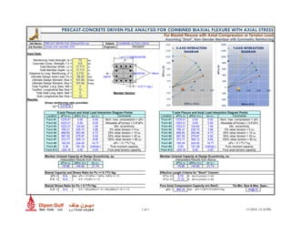
![0 5000 10000 15000 20000
1
3
5
7
9
11
13
15
17
19
21
23
25
27
29
31
33
35
37
39
41
SOIL STIFFNESS/ELEMENT
[KN/M2]
-30.00 -20.00 -10.00 0.00 10.00
1
3
5
7
9
11
13
15
17
19
21
23
25
27
29
31
33
35
37
39
41
AVERAGE SPRING FORCES
IN ELEMENTS [KN/M]
-21.00
-16.00
-11.00
-6.00
-1.00-0.002 0.000 0.002 0.004 0.006 0.008
HORIZONTAL
DISPLACEMENT [M]
-21.00
-16.00
-11.00
-6.00
-1.00
-50.0 0.0 50.0 100.0 150.0
BENDING MOMENT [KNM]
-21.00
-16.00
-11.00
-6.00
-1.00-20.0 0.0 20.0 40.0 60.0 80.0
SHEAR FORCE [KN]
0
0.2
0.4
0.6
0.8
1
0.001 0.002 0.003 0.004 0.005 0.006 0.007 0.008
LOAD FACTOR VS DISPLACEMENT OF TOP NODE
[M]
0
0.2
0.4
0.6
0.8
1
0.000 20.000 40.000 60.000 80.000 100.000 120.000 140.000 160.000
LOAD FACTOR VS MAX. BENDING MOMENT [KNM]](https://image.slidesharecdn.com/precastdrivenpile450x450-180415203910/85/Precast-driven-pile-450-x450-9-320.jpg)
![Soil properties Spring forces (last step) Pile forces (last step) Pile displacement and rotation (last step) Step-by-step results
k_soil F_max F_soil z F_soil z V M z ux q Fhstep ux,top |Mmax| NL Springs Iterations
Element [kN/m2
] [kN/m] Element [kNm] [m] [kN] [m] [kN] [kNm] [m] [m] [rad] Step [kN] [m] [kNm]
1 5000 5.0 1 -5.00 0.00 -1.3 0.00 70.0 138.8 0.00 0.007 0.0000 0.038462 2.69 0.0 4.023 12.0 2
2 5000 10.0 2 -10.00 -0.50 -3.8 -0.50 68.8 104.4 -0.50 0.007 -0.0006 0.076923 5.38 0.0 8.045 12.0 1
3 5000 15.0 3 -15.00 -1.00 -6.3 -1.00 65.0 71.9 -1.00 0.006 -0.0010 0.115385 8.08 0.0 12.068 12.0 1
4 5000 20.0 4 -20.00 -1.50 -8.8 -1.50 58.8 42.5 -1.50 0.006 -0.0013 0.153846 10.77 0.0 16.091 12.0 1
5 5000 25.0 5 -22.37 -2.00 -11.3 -2.00 50.0 17.5 -2.00 0.005 -0.0015 0.192308 13.46 0.0 20.114 12.0 1
6 5000 30.0 6 -20.38 -2.50 -11.1 -2.50 38.8 -1.8 -2.50 0.004 -0.0015 0.230769 16.15 0.0 24.290 13.0 2
7 5000 35.0 7 -16.76 -3.00 -9.3 -3.00 27.6 -15.6 -3.00 0.004 -0.0015 0.269231 18.85 0.0 28.678 13.0 1
8 5000 40.0 8 -13.38 -3.50 -7.5 -3.50 18.4 -24.8 -3.50 0.003 -0.0014 0.307692 21.54 0.0 33.065 13.0 1
9 5000 45.0 9 -10.33 -4.00 -5.9 -4.00 10.9 -30.3 -4.00 0.002 -0.0012 0.346154 24.23 0.0 37.903 14.0 2
10 5000 50.0 10 -7.67 -4.50 -4.4 -4.50 5.0 -32.8 -4.50 0.002 -0.0011 0.384615 26.92 0.0 42.965 14.0 1
11 5000 50.0 11 -5.40 -5.00 -3.2 -5.00 0.5 -33.0 -5.00 0.001 -0.0009 0.423077 29.62 0.0 48.026 14.0 1
12 5000 50.0 12 -3.53 -5.50 -2.2 -5.50 -2.7 -31.7 -5.50 0.001 -0.0007 0.461538 32.31 0.0 53.087 14.0 1
13 5000 50.0 13 -2.04 -6.00 -1.3 -6.00 -4.9 -29.3 -6.00 0.001 -0.0006 0.5 35.00 0.0 58.149 14.0 1
14 5000 50.0 14 -0.88 -6.50 -0.7 -6.50 -6.2 -26.2 -6.50 0.000 -0.0005 0.538462 37.69 0.0 63.602 15.0 2
15 5000 50.0 15 -0.02 -7.00 -0.2 -7.00 -6.9 -22.7 -7.00 0.000 -0.0003 0.576923 40.38 0.0 69.336 15.0 1
16 5000 50.0 16 0.57 -7.50 0.2 -7.50 -7.1 -19.2 -7.50 0.000 -0.0002 0.615385 43.08 0.0 75.070 15.0 1
17 5000 50.0 17 0.96 -8.00 0.4 -8.00 -6.9 -15.7 -8.00 0.000 -0.0002 0.653846 45.77 0.0 80.805 15.0 1
18 5000 50.0 18 1.17 -8.50 0.6 -8.50 -6.5 -12.4 -8.50 0.000 -0.0001 0.692308 48.46 0.0 86.539 15.0 1
19 5000 50.0 19 1.24 -9.00 0.6 -9.00 -6.0 -9.5 -9.00 0.000 0.0000 0.730769 51.15 0.0 92.562 16.0 2
20 5000 50.0 20 1.21 -9.50 0.6 -9.50 -5.3 -6.8 -9.50 0.000 0.0000 0.769231 53.85 0.0 98.969 16.0 1
21 5000 50.0 21 1.44 -10.00 0.6 -10.00 -4.7 -4.4 -10.00 0.000 0.0000 0.807692 56.54 0.0 105.376 16.0 1
22 11000 50.0 22 1.84 -10.50 0.8 -10.50 -4.1 -2.4 -10.50 0.000 0.0001 0.846154 59.2308 0.005456 111.8 16.0 1
23 11000 50.0 23 1.80 -11.00 1.0 -11.00 -3.3 -0.7 -11.00 0.000 0.0001 0.884615 61.9231 0.005813 118.2 16.0 1
24 11000 50.0 24 1.45 -11.50 0.8 -11.50 -2.3 0.4 -11.50 0.000 0.0001 0.923077 64.6154 0.006175 124.6 17.0 2
25 11000 50.0 25 1.11 -12.00 0.6 -12.00 -1.5 1.2 -12.00 0.000 0.0001 0.961538 67.3077 0.006615 131.7 17.0 1
26 11000 50.0 26 0.81 -12.50 0.5 -12.50 -0.8 1.6 -12.50 0.000 0.0001 1 70.0000 0.007055 138.8 17.0 1
27 11000 50.0 27 0.60 -13.00 0.3 -13.00 -0.4 1.8 -13.00 0.000 0.0000
28 15000 50.0 28 0.44 -13.50 0.3 -13.50 0.0 1.8 -13.50 0.000 0.0000
29 15000 50.0 29 0.26 -14.00 0.2 -14.00 0.2 1.7 -14.00 0.000 0.0000
30 15000 50.0 30 0.10 -14.50 0.1 -14.50 0.4 1.5 -14.50 0.000 0.0000
31 15000 50.0 31 -0.02 -15.00 0.0 -15.00 0.5 1.2 -15.00 0.000 0.0000
32 15000 50.0 32 -0.09 -15.50 0.0 -15.50 0.5 1.0 -15.50 0.000 0.0000
33 15000 50.0 33 -0.13 -16.00 -0.1 -16.00 0.5 0.7 -16.00 0.000 0.0000
34 15000 50.0 34 -0.15 -16.50 -0.1 -16.50 0.4 0.5 -16.50 0.000 0.0000
35 15000 50.0 35 -0.14 -17.00 -0.1 -17.00 0.3 0.4 -17.00 0.000 0.0000
36 15000 50.0 36 -0.13 -17.50 -0.1 -17.50 0.3 0.2 -17.50 0.000 0.0000
37 15000 50.0 37 -0.11 -18.00 -0.1 -18.00 0.2 0.1 -18.00 0.000 0.0000
38 15000 50.0 38 -0.09 -18.50 -0.1 -18.50 0.1 0.1 -18.50 0.000 0.0000
39 15000 50.0 39 -0.07 -19.00 0.0 -19.00 0.1 0.0 -19.00 0.000 0.0000
40 15000 50.0 40 -0.04 -19.50 0.0 -19.50 0.0 0.0 -19.50 0.000 0.0000
41 18000 41 -0.02 -20.00 0.0 -20.00 0.0 0.0 -20.00 0.000 0.0000
42 18000 42 0.00 -20.50 0.000 -20.50 0.0 0.0 -20.5000 1.2E-07 0.00
43 18000 43 0.00 -21.00 0.000 -21.00 0.0 0.0 -21.0000 -1.6E-06 0.00
44 18000 44 0.00 -21.50 0.00000 -21.50 0.0 0.0 -21.5000 -3.3E-06 0.00
45 18000 45 0.00 -22.00 0.000 -22.00 0.0 0.0 -22.0000 -5.1E-06 0.00
46 18000 46 0.00 -22.50 0.000 -22.50 0.0 0.0 -22.5000 -6.8E-06 0.00
47 18000 47 0.00 -23.00 0.000 -23.00 0.0 0.0 -23.0000 -8.5E-06 0.00
48 18000 48 0.00 -23.50 0.000 -23.50 0.0 0.0 -23.5000 -1E-05 0.00
49 18000 49 0.00 -24.00 0.000 -24.00 0.0 0.0 -24.0000 -1.2E-05 0.00
50 18000 50 0.00 -24.50 0.000 -24.50 0.0 0.0 -24.5000 -1.4E-05 0.00
51 18000 51 0.00 -25.00 0.000 -25.00 0.0 0.0 -25.0000 -1.5E-05 0.00
52 18000 52 0.00 -25.50 0.000 -25.50 0.0 0.0 -25.5000 -1.7E-05 0.00
-26.00 0.000 -26.00 0.0 0.0 -26.0000 -1.9E-05 0.00
Fhstep/ Fh](https://image.slidesharecdn.com/precastdrivenpile450x450-180415203910/85/Precast-driven-pile-450-x450-10-320.jpg)

This document provides the design and analysis of precast driven piles for a proposed 2x660MW thermal power project in Rampal, Bangladesh. It evaluates the pile for stresses during driving and lifting/pitching, and checks the axial, uplift, lateral and flexural capacities of the pile section. The analysis considers a 450mm x 450mm square precast pile with 26m length. It determines the pile can safely resist all assessed stresses and loads with the proposed reinforcement details.