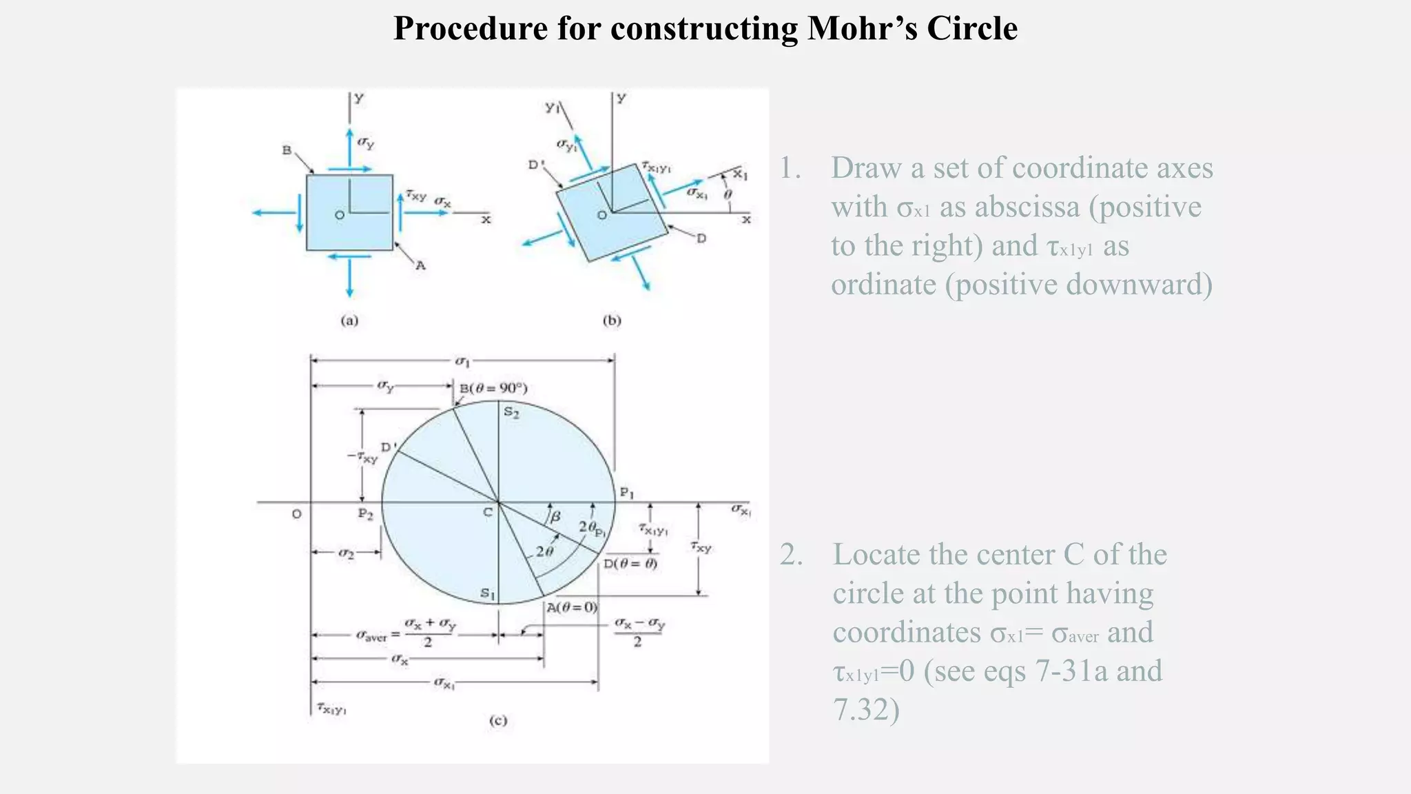
1) Mohr's circle is a graphical representation that can be used to analyze stresses and strains acting on inclined planes. It enables visualization of relationships between normal and shear stresses.
2) Using Mohr's circle, one can determine principal stresses, maximum shear stresses, and stresses on inclined planes given certain known stresses.
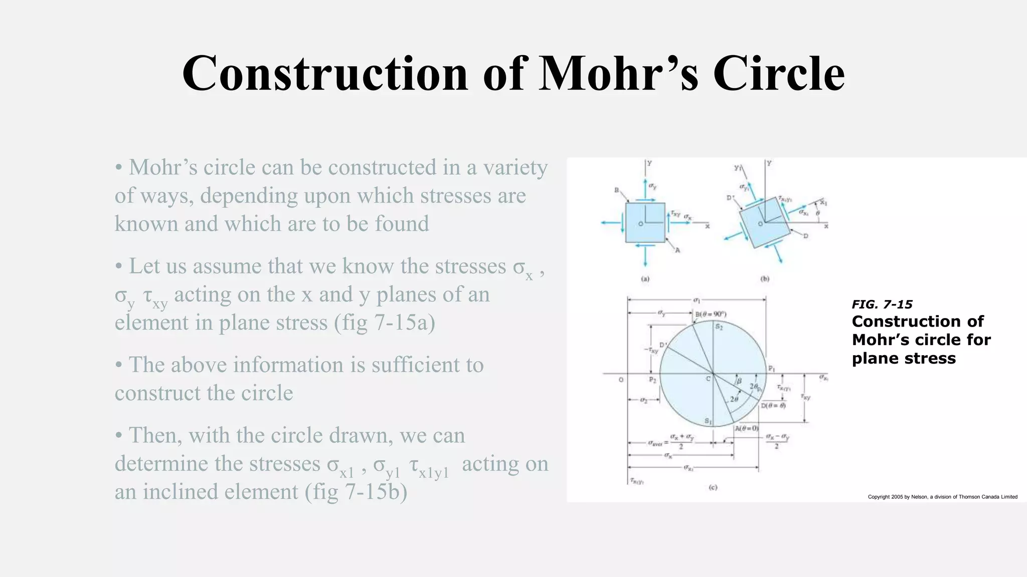
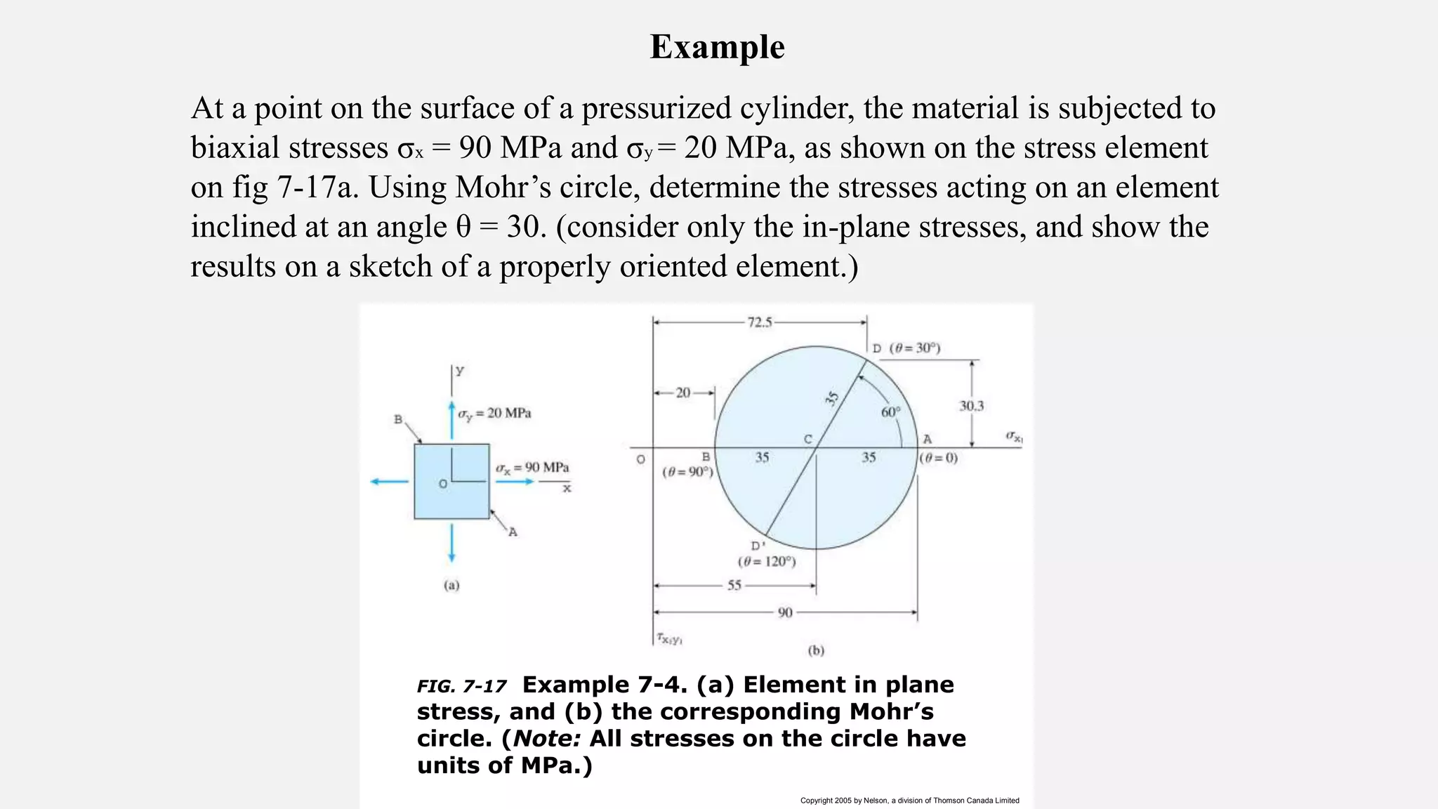
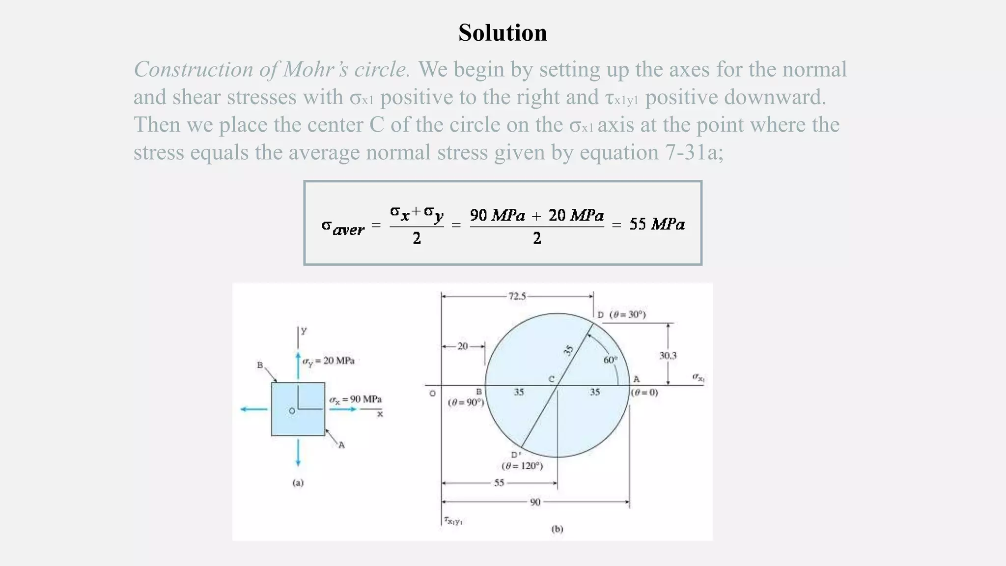
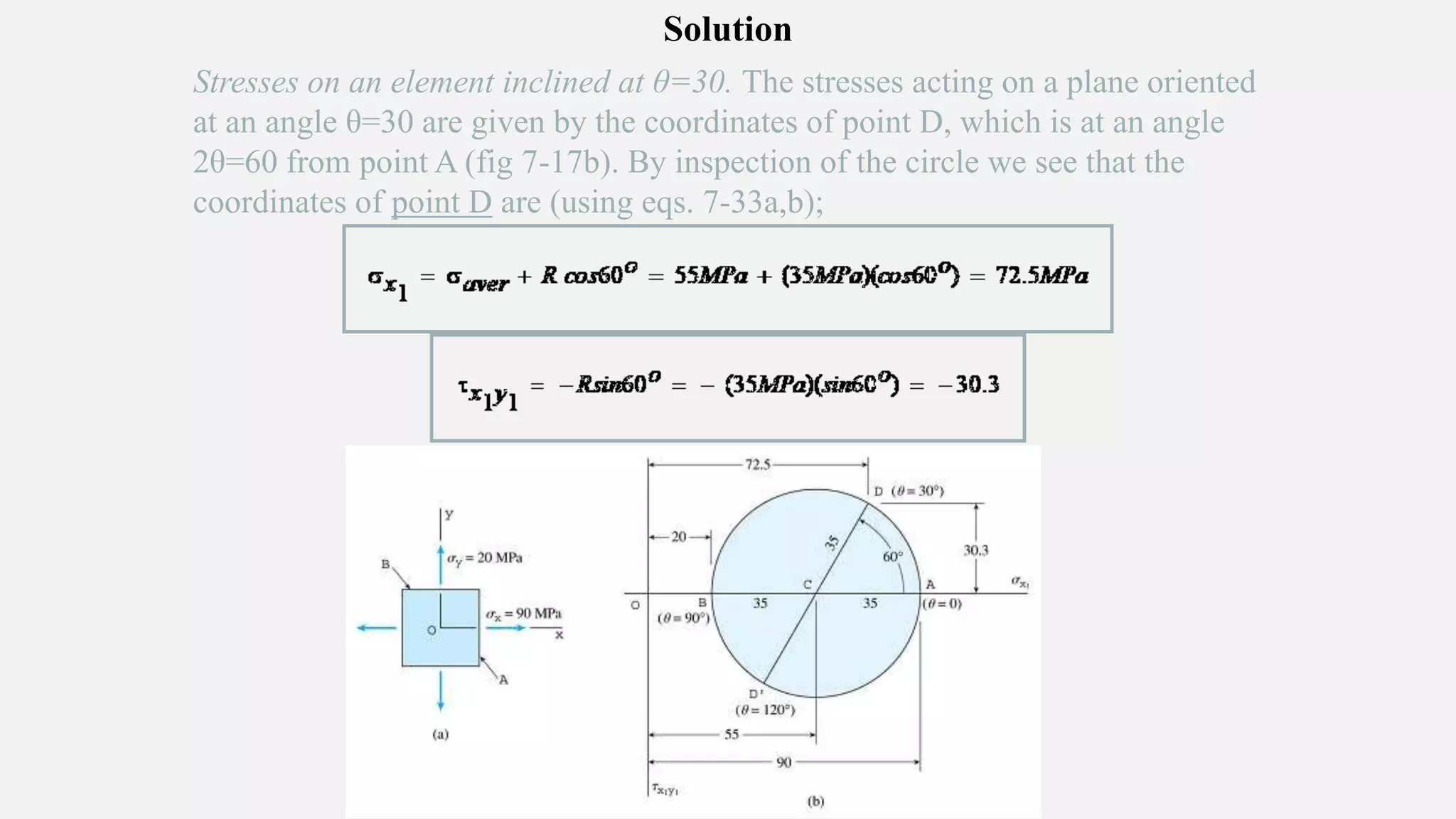
3) The document provides steps for constructing Mohr's circle to solve an example problem involving determining stresses on a plane inclined at 30 degrees, given principal stresses.