SlideShare a Scribd company logo
1 of 103
Download to read offline
Advanced Metal Forming Techniques
UNIT-1 INTRODUCTION TO THEORY OF PLASTICITY AND FORMING
The Plastic Deformation of Metal Crystals
Yield point (elastic limit)
Strain
Fig. 3.1, Verhoeven
When a material is stressed below its elastic limit:
When a material is stressed beyond its elastic limit:
Deep drawing of a cylindrical cup. (a) Before drawing; (b) after drawing
Yielding criteria
1. Criteria for yielding
(1) What is the meaning about yield criterion?
In this case the stress is un-axial and this point can readily be
determined. But what if there are several stress acting at a point in
different direction ?
⇒ The criteria for deciding which combination of multi-axial
stress will cause yielding are called criteria.
(2). Theory of yield criterion-
(A) Tresa criterion
Yielding will occur when the maximum shear stress reaches the
values of the maximum shear stress occurring under simple tension.
The maximum shear stress in multi-axial stress = the maximum
shear stress in simple tension
max
⎩
1
2
2 ,
1
2
3 ,
2
2
3
⎭

0
1
2
 





For pure shear (k )
1 2 0 ⇒ 1 −2 k 
1
2
2 1 2
又k 
1
2
2 
2
k
∴k 
2
⇒For pure shear(k) state, the yielding is happened if k 
2
(2)The von-Mises yield criterion

0
0
0
Yielding begin when the octahedral shear stress reaches the
octahedral shear stress at yield in simple tension.
Mohr’s Circle for Plane Stress
Transformation equations for plane stress. Procedure for constructing Mohr‘s circle. Stresses on an
inclined element.
Principal stresses and maximum shear stresses. Introduction to the stress tensor.
1
Stress Transformation Equations
σy
y
1
y
σ τy1x1
τyx
τx1y1
x
1
y1
τxy
y
σ
x1
σx
x
σx θ x
σ
x1
τ
xy
τ
x1y1
τ
y1x1
τ
yx
σy1
σx +σ y σx −σ y
σx1 = + cos 2θ + τxy sin 2θ2 2
τ
x1y1 = −
(σ x −σ y )
sin 2θ + τxy cos 2θ
2
If we vary θ from 0° to 360°, we will get all possible values of σ x1 and τx1y1 for a given stress state. It would be useful to represent
σx1 and τx1y1 as
functions of θ in graphical form.
To do this, we must re-write the transformation equations.
σ
x1 −
σx +σ y
=
σx −σ y
cos 2θ + τxy sin 2θ2 2
τ
x1y1 = −
(σ x −σ y )
sin 2θ + τxy cos 2θ
2
Eliminate θ by squaring both sides of each equation and adding the two equations together.
σ
x
+ σ
y
2
2
σ
x
−σ
y
2
2
− =σ
x1
2
+ τ
x1y1
2
+ τxy
Define σavg and R
σ
x
+σ
y
σ
x
−σ
2
2
σ
avg =
R =
y
2 2
+ τxy
3
Substitue for σavg and R to get
(σ x1 − σavg )2
+ τx1y1
2
= R2
which is the equation for a circle with centre (σavg,0) and radius R.
This circle is usually referred to as Mohr’s circle, after the German civil
engineer Otto Mohr (1835-1918). He developed the graphical technique for
drawing the circle in 1882.
The construction of Mohr‘s circle is one of the few graphical techniques
still used in engineering. It provides a simple and clear picture of an
otherwise complicated analysis.
4
Sign Convention for Mohr’s Circle
y1
y
(σx1 − σavg )
2 2
= R
2
+ τ
x1y1
σ τy1x1
τx1y1 x1
y1
2θx1
σ
θ
σavg
x
x1
R
σ
x1
τ
y1x1
τ
x1y1 σy1
τx1y1
Notice that shear stress is plotted as positive downward.
The reason for doing this is that 2θ is then positive counterclockwise, which agrees with the direction of 2θ used in the
derivation of the tranformation equations and the direction of θ on the stress element.
Notice that although 2θ appears in Mohr‘s circle, θ appears on the stress element.
5
Procedure for Constructing Mohr’s Circle
1. Draw a set of coordinate axes with σx1 as abscissa (positive to the right) and τx1y1 as ordinate (positive downward).
2. Locate the centre of the circle c at the point having coordinates σx1
= σavg and τx1y1 = 0.
3. Locate point A, representing the stress conditions on the x face of the element by plotting its coordinates σx1 = σx and
τx1y1 = τxy. Note that point A on the circle corresponds to θ = 0°.
4. Locate point B, representing the stress conditions on the y face of the element by plotting its coordinates σx1 = σy and
τx1y1 = −τxy. Note that point B on the circle corresponds to θ = 90°.
5. Draw a line from point A to point B, a diameter of the circle passing through point c. Points A and B (representing stresses
on planes at 90° to each other) are at opposite ends of the diameter (and therefore 180° apart on the circle).
6. Using point c as the centre, draw Mohr‘s circle through points A and B. This circle has radius R.
(based on Gere)
6
B
σy
τyx
σy
σx
y
x
τxy
σx
B (θ=90)
τxy A
-τxy τyx
c
σ
x1
R
τ
xy
A (θ=0)
σ
avg σ
x
τ
x1y1
7
Stresses on an Inclined Element
1. On Mohr‘s circle, measure an angle 2θ counterclockwise from radius cA, because point A corresponds to θ = 0
and hence is the reference point from which angles are measured.
2. The angle 2θ locates the point D on the circle, which has coordinates σx1 and τx1y1. Point D represents the stresses on
the x1 face of the inclined element.
3. Point E, which is diametrically opposite point D on the circle, is located at an angle 2θ + 180° from cA (and 180°
from cD). Thus point E gives the stress on the y1 face of the inclined element.
4. So, as we rotate the x1y1 axes counterclockwise by an angle θ, the point on Mohr‘s circle corresponding to the x1
face moves counterclockwise through an angle 2θ.
(based on Gere)
8
B
σy
τyx
σ
y1 y
τxy
B (θ=90)
σx
x
σx
τxy A
E (θ+90) 2θ+180
τyx
-τ
x1y1
σ
x1
τ
x1y1
c
D (θ)
R
y
2θ y1
τy1x1σ
τx1y1
x1A (θ=0)
y1
E
σ
x1
σ
x1
θ D
x
σ
x1 τ
y1x1
τ
x1y1
τ
x1y1
σy1
9
Principal Stresses B
σ
y
τyx
y
τxy
B (θ=90)
σx
x
σx
2θ
p2 τxy
τyx
A
σ2 c σ
1
σ
x1
R
2θ
p1 y
σ
2A (θ=0)
P2 σ1
θp2
P1 xθp1
σ1
τ
x1y1
σ2
aximum Shear Stress B
σy
τyx
y
τxy
B (θ=90) σx x σx
τ
min
2θs
τxy
τyx
A
c σ
x1 Note carefully the
y directions of the
τ
max R
shear forces.
σs
A (θ=0) τmax σ
s
σ
s
τmax θs τmax
x
σs τmax
τ
x1y1
σs
11
Example: The state of plane stress at a point is represented by the stress element below. Draw the Mohr‘s circle, determine the principal
stresses and the maximum shear stresses, and draw the corresponding stress elements.
c =σavg =
σx +σ y
=
−80 +50
= −15
σ
1,2 = c ± R
2 2
σ
1,2 = −15 ± 69.6
R = (50 −(− 15)) 2
+(25 )2
σ1 = 54.6 MPa
R = 65
2
+ 25
2
= 69.6 A (θ=0)
σ2 = −84.6 MPa
σ2 σ
c
1
σ
B
50 MPa R
B (θ=90)
80 MPa
y
80 MPax τ
max τmax = R = 69.6 MPa
A
50 MPa
25tan 2θ2 = = 0.3846
y
80 −15
2θ2 = 21.0°
80 MPa x 80 MPa
2θ1 = 21.0 +180° = 201°
25 MPa θ1 =100.5° θ2 =10.5°
50 MPa
A (θ=0)
σ2 σ
1
σ
y
2θ2 c
54.6 MPa R
B (θ=90)
84.6 MPa
2θ1
o
100.5
84.6 MPa
10.5o
x
2θ
54.6 MPa
τ
13
50 MPa
y
80 MPa x 80 MPa
2θ2 = 21.0°
2θs min = −(90 − 21.0) = −69.0° θs min = −34.5°
25 MPa
50 MPa
τ
min
taking sign convention into account
A (θ=0)
2θ
smin
y 2θ2 c
2θ
σ
15 MPa
15 MPa
2θ
smax
55.5o
x-34.5o
R
B (θ=90)
15 MPa
τmax
15 MPa
2θ2 = 21.0°
2θs max = 21.0 +90° =111.0°
69.6 MPa τ
θ
s max = 55.5°
14
Example: The state of plane stress at a point is represented by the stress element below. Find the stresses on an element inclined at
30° clockwise and draw the corresponding stress elements.
50 MPa
C (θ = -30°)y
80 MPa x 80 MPa
A (θ=0) -
25 MPa
50 MPa
y
y1 2θ2
25.8 MPa
4.15 MPa
D
-60+180°
x-30o
25.8 MPa D (θ = -30+90°)
4.15 MPa C x1
68.8 MPa
σx1 = c – R cos(2θ2+60) σy1 = c + R
cos(2θ2+60)
τx1y1= -R sin (2θ2+60) σx1 = - 26
σy1 = -4
τx1y1= -69
σ
B (θ=90)
2θ
θ = -30°
τ
2θ = -60°
15
Principal Stresses σ1 = 54.6 MPa, σ2 = -84.6 MPa But we have forgotten about the third
principal stress!
Since the element is in plane stress (σz = 0), the third principal stress is zero.
σ1 = 54.6 MPa
σ2 = 0 MPa
σ3 = -84.6 MPa
This means three Mohr‘s circles
can be drawn, each based on two
principal stresses:
σ1 and σ3 σ1 and
σ2 σ2 and σ3
A (θ=0)
σ
3 σ2 σ
1 σ
B (θ=90)
τ
16
σ3
σ σ1
1
σ3
σ3
σ3
σ1 σ
1σ
3
σ3
σ1 σ1
σ
3
σ2 σ
1 σ
τ
17
The stress element shown is in plane stress. B
σy
What is the maximum shear stress?
y
σx
x
B
τxy
τyx
σ
3 σ2 σ1
σ
x1
τ
max(1,2)
=
σ
1 −σ
2
2
A
τ
max(2,3)
=
σ2 −σ3
2
τyx
τxy
σx
A
= σ
2
2
overall maximum
τ
max(1,3) =
σ1 −σ3
=
σ
1
τ
x1y1
2 2
18
Introduction to the Stress Tensor
y
σ
yy
τ
yx
τ
yz
τ
xy
σ
xx τ
xy τ
xz
τ
zy τ
yx σ
yy τ yz
σ
xx
σ
xx x
τ τ σ
τ
zx τ
xz zx zy zz
σ
zz
Normal stresses on the diagonal
z
Shear stresses off diagaonal
σ
yy
τ
xy = τ
yx, τ
xz = τ
zx, τ
yz = τ
zy
The normal and shear stresses on a stress element in 3D can be assembled into a 3x3 matrix known as the stress tensor.
19
From our analyses so far, we know that for a given stress system, it is possible to find a set of three principal stresses. We also know
that if the principal stresses are acting, the shear stresses must be zero. In terms of the stress tensor,
σ τ
τ
xx
τ
xy
τ
xz
σ
1
0 0
yx
σ
yy
τ
yz
0 σ
2
0
zx τ
zy σ
zz 0 0 σ
3
In mathematical terms, this is the process of matrix diagonaliza-tion in which the eigenvalues of the original matrix are just the
principal stresses.
20
Example: The state of plane stress at a point is represented by the stress element below. Find the principal stresses.
50 MPa
80 MPa
y
80 MPax
25 MPa
50 MPa
σ
x
τ −80 − 25
xy
M = =
− 25 50
τ
yx σ
y
We must find the eigenvalues of this matrix.
Remember the general idea of eigenvalues. We are looking for values of λ such that:
Ar = λr where r is a vector, and A is a matrix.
Ar – λr = 0 or (A – λI) r = 0 where I is the identity matrix.
For this equation to be true, either r = 0 or det (A – λI) = 0. Solving the latter equation (the ―characteristic equation‖)
gives us the eigenvalues λ1 and λ2.
21
−80 –λ − 25
= 0det
− 25 50 −λ
(−80 −λ)(50 −λ) −(−25)(−25) = 0
λ2
+30λ − 4625 = 0
So, the principal stresses are –84.6 MPa and
λ = −84.6, 54.6 54.6 MPa, as before.
Knowing the eigenvalues, we can find the eigenvectors. These can be used to find the angles at which the principal stresses act.
To find the eigenvectors, we substitute the eigenvalues into the equation (A – λI ) r = 0 one at a time and solve for r.
−80 − λ − 25 x 0
=
− 25 050 −λ y
−80 −54.6 − 25 x 0
=
− 25 50 −54.6 0y
−134.6 − 25 x 0
=
− 25 − 4.64 0
y
x = −0.186 y
−0.186
is one eigenvector.1
22
−80 −λ − 25 x 0
=
− 25 50 −λ y 0
−80 −(−84.6) − 25 x 0
=
− 25 50 −(−84.6) 0y
4.6 −25 x 0
=
−25 134.6 0
y
x = 5.388 y
5.388
is the other eigenvector.
1
Before finding the angles at which the principal stresses act, we can check to see if the eigenvectors are correct.
54.6 0 −0.186 5.388 −80 −25
CD =
0 −84.6
=
1 1
M =
− 25 50
D = C−1
M C
C −1
=
1
AT
where A = matrix of co - factorsdet C
−1 −0.179 0.967
C =
0.179 0.033
−0.179 0.967−80 − 25 −0.186 5.388 54.6 0
D =
0.179 0.033 − 25 50 1 1
=
0 −84.6
To find the angles, we must calculate the unit eigenvectors:
−0.186 −0.183 5.388 0.938
→ →
1 0.983 1 0.183
And then assemble them into a rotation matrix R so that det R = +1.
0.983 −0.183
det R = (0.983)(0.983) −(0.183)(−0.183) =1R =
0.183 0.983
The rotation matrix has the form
Cosθ −sinθ
′ T
D = R M RR =
cosθSinθ
So θ = 10.5°, as we found earlier for one of the principal angles.
24
Using the rotation angle of 10.5°, the matrix M (representing the original stress state of the element) can be transformed to matrix
D’ (representing the principal stress state).
D′ = RT
M R
′
0.983 0.183 −80
D =
−0.183 0.983 −25
′
−84.6 0
D =
0 54.6
y
54.6 MPa
o 84.6 MPa
100.5
84.6 MPa
x10.5o
−25 0.983 −0.183
50 0.183 0.983
So, the transformation equations, Mohr‘s circle, and eigenvectors all give
the same result for the principal stress element.
54.6 MPa
25
Powder metallurgy (PM) is the production and utilization of metal powders. Powders are defined as particles
that are usually less than 1000 nm (1 mm) in size. Most of the metal particles used in PM are in the range of 5 to
200 mm (0.2 to 7.9 mils). To put this in context, a human hair is typically in the 100 mm (3.9 mils) range.
The history of PM has already been outlined in the article ―History of Powder Metallurgy‖ in this Volume.
This article reviews the various segments of the PM process from powder pro-duction and powder processing
through to the characterization of the materials and their prop-erties. It will cover processing methods for con-
solidating metal powders including options for processing to full density.
Powders have a high ratio of surface area to volume and this is taken advantage of in the use of metal powders
as catalysts or in various chemical and metallurgical reactions. While this article focuses on the use of powders
to make functional engineering components, many metal powders are used in their particulate form. This aspect
of PM is covered in the arti-cle ―Specialty Applications of Metal Powders‖ in this Volume.
Powder technologies are exciting to engi-neers because processing options permit the selective placement of
phases or pores to tailor the component for the application. The capabil-ity of press and sinter processing or
metal injec-tion molding (MIM) processing to replicate parts in high volumes is very attractive to design
engineers. The ability to fabricate complex shapes to final size and shape or to near-net shape is particularly
valuable. Powder metal-lurgy offers the potential to do this in high volumes and also for applications where the
volumes are not so large.
The three main reasons for using PM are eco-nomic, uniqueness, and captive applications, as shown in Fig. 1
(Ref 1). For some applications that require high volumes of parts with high precision, cost is the overarching
factor. A good example of this segment is parts for the auto-motive industry (where approximately 70% of
ferrous PM structural parts are used). Powder metallurgy parts are used in engine, transmis-sion, and chassis
applications. Sometimes it is a unique microstructure or property that leads to the use of PM processing: for
example, porous filters, self-lubricating bearings, dispersion-strengthened alloys, functionally graded materi-als
(e.g., titanium-hydroxyapatite), and cutting tools from tungsten carbide or diamond com-posites. Captive
applications of PM include materials that are difficult to process by other techniques, such as refractory metals
and reac-tive metals. Other examples in this category are special compounds such as molybdenum disili-cide and
titanium aluminide, or amorphous metals.
The metal powder industry is a recognized metal forming technology that competes dir-ectly with other
metalworking practices such as casting, forging, stamping (fine blanking),
Fig. 1 Three main reasons for choosing powder metallurgy shown in the form of a Venn diagram. The
intersection of the three circles represents
an ideal area for applying PM techniques. Source: Ref 1
and screw machining. The industry comprises powder suppliers and parts makers, plus the companies that
supply the mixing equipment, powder handling equipment, compacting presses, sintering furnaces, and so forth.
Powder metallurgy processing offers many advantages. The PM process is material and energy efficient
compared with other metal forming technologies. Powder metallurgy is cost effective for making complex-
shaped parts and minimizes the need for machining. A wide range of engineered materials is available, and
through appropriate material and process selec-tion the required microstructure may be devel-oped in the
material. Powder metallurgy parts have good surface finish and they may be heat treated to increase strength or
wear resistance. The PM process provides part-to-part reproduc-ibility and is suited to moderate-to-high volume
production. Where necessary, controlled micro-porosity can be provided for self-lubrication or filtration. While
dimensional precision is good, it typically does not match that of machined parts.
In the case of ferrous PM parts, they have lower ductility and reduced impact resistance compared with
wrought steels.
The majority of PM parts are porous and con-sideration must be given to this when performing finishing
operations.
Metal Powders
Metal powders come in many different shapes and sizes (Fig. 2). Their shape, size, and size dis-tribution
depend on the manner in which they were produced. Metal powder production is cov-ered in depth in various
articles in the Section, ―Metal Powder Production‖ in this Volume.
There are three main methods of powder production:
Mechanical, including machining, milling, and mechanical alloying
Chemical, including electrolytic deposition, decomposition of a solid by a gas, thermal
Introduction to Powder Metallurgy
5 μm 5 μm
Fig. 2 Example of the different particle shapes possible with metal powders
limited plasticity. Rigid die compaction is not suitable for consolidating such powders, and they must be
processed by other means such as hot pressing, extrusion, or hot isostatic pressing (HIP), described subsequently
in this article.
Highly reactive metal powders are also not suitable for rigid die compaction. They generally need to be
vacuum hot pressed, or encapsulated and extruded, or HIPed.
Rigid die compacted parts and MIM parts are thermally treated to increase their strength in a process known as
sintering. The parts are heated, generally in a reducing atmosphere, to a temperature that is below the melting
point of the primary constituent of the material, in order to form metallurgical bonds between the compacted
metal powder particles. Sintering is a ―shrinkage‖ process. The system tries to reduce its overall surface area via
various diffu-sion processes. Metallurgical bonds (micro-
decomposition, precipitation from a liquid, precipitation from a gas, solid-solid reactive synthesis
Physical, including atomization techniques
Most metals are available in powder form. Some may be made by many different methods, while for others
only a few options are possible. The characteristics of the powder are deter-mined by the method by which it is
produced. The shape, size, size distribution, surface area, apparent density, flow, angle of repose, com-
pressibility, and green strength depend on the powder production method. In-depth coverage of the sampling and
testing of metal powders is presented in the articles in the Section ―Metal Powder Characterization‖ in this
Volume.
Powder Processing
For the production of PM parts in high volumes, compaction is carried out in rigid dies. In most instances, the
metallic powders are mixed with a lubricant (e.g., ethylene bis-stearamide) to reduce interparticle friction dur-
ing compaction and to facilitate ejection of the compacted parts by reducing friction at the die-wall and core-rod
interfaces.
The metal powders may be elemental pow-ders; mixtures of elemental powders; or mix-tures of elemental
powders with master alloys or ferroalloys, prealloys, diffusion alloys, or hybrid alloys. See the article ―Ferrous
Powder Metallurgy Materials‖ in this Volume for an in-depth review of the alloying methods used in ferrous
PM. A consequence of the various alloying methods available is that only the PM materials made from
prealloyed powders are chemically homogeneous. The other alloying methods can result in chemically
inhomoge-neous materials. The hardenability is determined by the local chemical composition, and the resulting
microstructures are generally quite complex. Chemical analysis can be a challenge due to the inhomogeneous
nature of the materi-als. Guidelines for sample preparation for the
chemical analysis of the metallic elements in PM materials are provided in MPIF Standard 67 (Ref 2).
Complex, multilevel PM parts compacted in rigid dies will not have the same green density throughout. While
the objective is gen-erally to achieve a density as uniform as pos-sible throughout the compacted part, taller parts
and parts with multiple levels are subject to the presence of density differences between adjacent regions. This is
due to frictional effects and compacting tool deflections. Taller parts will have a neutral zone or density line—
the region of the compact that has experienced the least relative movement of powder. The position of the
neutral zone may be adjusted by varying the pressure exerted by the upper and lower punches.
Compaction in rigid dies is limited to part shapes that can be ejected from the die cavity. Parts with undercuts,
reverse tapers, threads, and so forth, are not generally practical. Such features are formed by postsintering
machining operations.
There are two main types of compacting press: mechanical and hydraulic. Some hybrid presses offer features
of both. A detailed treat-ment of compaction is provided in the Section ―Metal Powder Compaction‖ in this
Volume.
Some PM parts are molded (shaped) rather than compacted. Fine-particle-size metal pow-ders (5 to 20 mm, or
0.2 to 0.8 mils) are mixed with binders and plasticizers and processed to form a feedstock for MIM. Molding is
per-formed using machines similar to those used for plastic injection molding. Shrinkage during the subsequent
sintering operation is extensive (15 to 20%) due to the fine-particle-size pow-ders used and the high sintering
temperatures. Because the parts are molded and not com-pacted, they do not contain density gradients that lead
to distortion or problems with dimen-sional control. The process makes complex-shaped, small-to-medium sized
PM parts with high relative densities.
Some metal powders are not very compress-ible. The powder particles are hard and have
scopic weldments) form between adjacent metal particles (after oxides have been reduced on the surface of the
powder particles), pore surfaces become less irregularly shaped, and larger pores grow at the expense of the
smaller pores. Sintering is generally carried out using continuous mesh-belt furnaces. For higher temperatures
(1150 C, or 2100 F), pusher, roller hearth, or walking-beam furnaces may be used. Batch furnace processing is
used for special applications (e.g., pressure-assisted sintering). More information on sintering may be found in
the Section ―Sintering Basics‖ in this Volume.
Powder Metallurgy Material
Properties
The majority of PM parts contain pores (see options for processing metal powders to full density later in this
article). This is an advan-tage when metal powders are used to make self-lubricating bearings in which the
surface-connected pores of the parts are impregnated with oil. When the bearing surface heats up due to
frictional heat, oil is released from the pores. When the bearing cools, the oil is sucked back into the pore
channels by capillary action. The porosity in PM parts has an effect on the physical, mechanical, magnetic,
thermal, wear, and corrosion properties of the parts.
Thermophysical properties of sintered steels, in particular their coefficient of thermal expan-sion and their
thermal conductivity, are needed when designing parts and when modeling heat treatment processes. Opinions
differ in the PM community as to the effect of density on these properties. Danninger has shown, how-ever, that
the coefficient of thermal expansion up to 1000 C (1832 F), measured through dilatometry, is virtually
independent of porosity (density) over a density range from 5.97 to 7.53 g/cm3
(Ref 3). In addition, thermal con-
ductivity was determined in the same tempera-ture range by using laser flash to measure thermal diffusivity, and
specific heat, and then
Powder Metallurgy Methods and
Applications / 11
the thermal conductivity was calculated from these parameters and the density in accordance with:
a ¼ l rCp (Eq 1)
where a is thermal diffusivity, l is thermal conductivity, r is density, and Cp is specific heat at constant pressure.
Thermal conductivity was shown to depend on density. The effect of porosity in the tech-nically relevant
density range was, however, slightly less pronounced than the effect exerted by the alloying elements;
specifically, the vari-ation observed between different standard PM steel grades in the low-to-medium
temperature range. Both thermophysical properties are, therefore, significantly less influenced by poros-ity than
by chemical composition. Powder met-allurgy steels are more similar to wrought steels than was generally
assumed.
The elastic constants are also of interest to the design engineer. Young‘s modulus, Pois-son‘s ratio, and the
shear modulus are related according to:
E ¼ 2Gð1 þ nÞ (Eq 2)
where E is Young‘s modulus, G is shear modulus, and n is Poisson‘s ratio. E and n are determined by resonant
frequency and G is calculated from Eq 2.
Beiss (Ref 4) has shown that:
E ¼ E0ðr=r0Þm
(Eq 3)
where E0 is the Young‘s modulus of the pore-free material, r is the density of the material, r0 is the density of the
pore-free material, and the exponent m depends on the pore morphology and varies between 2.5 and 4.5.
Nevertheless, over the density range of interest for ferrous PM structural materials, 6.4 to 7.4 g/cm3
, Young‘s
modulus is essentially a linear function of density (Fig. 3) (Ref 5).
Poisson‘s ratio is a weak function of density, and for ferrous PM structural steels it can be taken as 0.27 ± 0.02.
The mechanical properties of PM materials are a function of density:
P=P0 ¼ ðr=r0Þm
(Eq 4)
where, P is the property of interest, P0 the value for the pore-free material, r is the density of the material, r0 is
the density of the pore-free material, and m is an exponent the value of which depends on a given property (Fig.
4) (Ref 6–7). While tensile strength increases in a linear fashion as density increases, tensile ductility is more
dependent on reducing the level of porosity. Fatigue performance is even more influenced by density with an
exponent m of between 3.5 and 4.5. Impact energy is the most dependent on density, with an expo-nent m of
approximately 12.
Magnetic properties of ferrous PM materials are affected by density. Induction and per-meability increase as
the density is increased. Permeability and coercive field strength are structure-sensitive properties that are
degraded by the presence of impurities. The sintering con-ditions are extremely important to keep carbon,
nitrogen, and oxygen contents to low levels (C = 0.03 wt% max; N = 0.01 wt% max; and O = 0.10 wt% max).
Residual stresses from operations such as sizing, machining, or shot peening degrade the magnetic properties.
The properties can be restored through an annealing treatment.
Processing Options to Consolidate Metal Powders
There are three basic approaches to the con-solidation of metal powders, as shown in Fig. 5 (Ref 8).
Pressure-based compaction establishes density via the compaction process then sinters
to develop strength in the compacts. Rigid die compaction falls into this category and is the most cost-effective
method for the high-volume production of PM structural parts. In order for this method to be viable, the metal
powders need an irregular shape and good flow character-istics, they must be compressible, and they must have
good ―green‖ strength. (Green is the term used to describe an as-pressed compact.) Extremely hard particles with
a spherical shape are not appropriate for use in rigid die compac-tion. Compaction takes place at high pressure in
confined dies (the dies are generally made from cold work tool steel or cemented carbide). Compacting pressures
for ferrous powders are generally in the range from 400 to 700 MPa (60 to 100 ksi), from 100 to 400 MPa (14.5
to 60 ksi) for aluminum and aluminum alloy pow-ders, and approximately 400 MPa (60 ksi) for copper and
copper-alloy powders.
The green density increases as the compact-ing pressure is increased and levels out at higher compacting
pressures. Powder particles work harden as the result of plastic deformation and it requires higher pressures to
cause further plastic flow. In addition, the lubricant that is typically admixed to aid particle rearrangement and to
reduce the fictional forces between the powder and the compacting tools eventually has no place to go because
all the voids between particles have been closed—either by metal flow or by the presence of lubricant. More
lubricant is beneficial at lower compact-ing pressures, but there is a transition point at which the additional
lubricant impedes further densification (Fig. 6) (Ref 9).
Warm compaction processing was developed to overcome the compressibility constraints of rigid-die
compaction (Ref 10). The powder mixture and the compacting tools are heated
52 7.5
51 7.4
Young‘smodulus,GPa
50 7.3
psi6
49 7.1
Young‘smod
ulus,10
48 7.0
47 6.8
46 6.7
45 6.5
44 6.4
6.4 6.6 6.8 7.0 7.2 7.4 7.6
Sintered
density, g/cm3
Fig. 3 Young‘s modulus as a function of sintered density. Data from Ref 5
Fig. 4 Effect of density on mechanical and physical properties of PM materials. Source: Ref 6
12 / Introduction to Powder
Metallurgy
Fig. 5 Three basic approaches to the consolidation of metal powders. Source: Ref 8
to approximately 120 C (250 F) and the powder is compacted in a single press stroke. Green densities of up to
7.3 g/cm3
are possible with highly compressible ferrous powders. This is approximately 98% of the pore-free
density of the powder mixture being compacted (The pore-free density of the powder mixture is the green
density that could be reached if all the porosity was removed from the material. It can be calculated for any
mixture based on the density and the amount of each constituent in the mixture and the volume they would
occupy in the pore-free condition.) Special lubricants and binder-treated premixes were developed for warm
compaction. The efficiency of the special lubricant enabled it to be reduced to 0.6 wt% from the 0.8 wt% more
typically used for rigid-die compaction: the pore-free density increases by 0.1 g/cm3
for each 0.2 wt% reduc-tion
in the amount of the admixed lubricant. Examples of warm compacted parts are shown in Fig. 7.
More recently, warm-die compaction has been introduced. In this instance, only the com-pacting tooling is
heated (the powder is not heated). The optimal die temperature varies according to the specific lubrication
system being used. The die temperature is set so that the surface temperature of the green compacts reaches the
desired range for the lubricant sys-tem in question. Warm-die compaction is ideal for small-to-medium size parts
that weigh less than 700 g (1.5 lb), are up to 32 mm (1.3 in.) high, and have wall thicknesses of up to 19 mm
(0.75 in.). For larger parts warm com-paction processing is required. Green densities of 7.45 g/cm3
have been
reached using warm-
Contacting
pressure, ksi
58.0 72.5 87.0 101.5 116.0
130.
5
7.
4
7.
3
3
7.
2
g/c
m
7.
1
Transi
tion pressure
density,
7.
0
Green
6.
9
Atomi
zed iron
6.
8
6.
7
500 600 700 800 900400
Compacting
pressure, MPa
0.5%
Zn St
0.75% Zn
St
1.0%
Zn St
Fig. 6 Effect of lubricant content on the compressibility of metal powders. Source: Ref 9
Fig. 7 Examples of warm compacted PM parts. (a) Torque converter hub. Courtesy of Chicago Powder Metal
Products. (b) Transmission output shaft hub. Courtesy of GKN Sinter Metals. (c) Hand tool parts.
Courtesy of PoriteTaiwan Co. Ltd.
die compaction with lubricant additions of approximately 0.3 wt% (Ref 11).
In sintering-based densification, the shape of the component is formed in a molding oper-ation (e.g., MIM) and
sintering is enhanced by the use of high temperatures and fine-particle-size powders. While extensive shrinkage
occurs during sintering, it is essentially isotropic in nature so that good tolerance can still be achieved. Metal
powder loading in the feed-stock used for MIM is approximately 60%. The binders and plasticizers added to
make the mixture moldable must be removed prior
to final sintering. This ―debinding‖ step is the rate-controlling phase of the MIM process. Other sintering-based
densification processes that involve the molding or shaping of powders are slip casting and tape casting.
Hybrid Densification. For some materials, a hybrid densification process is used in which pressure and
temperature are applied at the same time. As mentioned previously, some powders are not suitable for rigid-die
compaction; they are too hard, are spherical in shape, or are too reactive. In this instance, processes such as pow-
der extrusion (typically after encapsulation) or
HIP are used. Hot pressing (often in vacuum) or spark sintering may also be used.
Processing to Full Density
Options for processing metal powders to full density are mapped in Fig. 8 (Ref 12). The ver-tical axis relates to
relative stress (the applied pressure divided by the in situ yield strength of the material) and the horizontal axis
relative temperature (based on the melting temperature of the material).
Full-density processing requires the simulta-neous application of pressure and temperature. The approach
works because most materials soften as temperature is increased. They also become more ductile and deform
with less work hardening.
The processing options fall into the following categories:
Low-stress processes that operate at high temperatures and are dominated by diffusion
processes (e.g., liquid-phase sintering)
Processes that apply intermediate stress levels and operate at intermediate temperatures and
rely on diffusional creep processes (e.g., hot pressing or HIP)
High-stress routes that operate at high strain rates and lower temperatures (powder forging
or extrusion)
Routes that achieve high density via the application of ultrahigh-stress at ambient temperature (explosive
compaction)
Liquid-phase sintering results in a composite microstructure that consists of a skeleton of a high-melting-
temperature phase in a matrix of a solidified liquid—for example, W-Ni-Fe heavy alloys, WC-Co cemented
carbides.
Hot pressing is performed in a rigid die using uniaxially applied pressure: it is a low-strain-rate process.
Graphite dies may be used, in which case induction heating may be employed. Hot pressing cycle times are slow
compared with rigid-die compaction. Vacuum is sometimes used to minimize contamination of the compact.
Diamond-metal-composite cutting tools are often hot pressed. Spark sintering is a process related to hot pressing.
In spark sintering, direct resistance heating is applied to the punches, die, and powder mass during consolidation.
Hot isostatic pressing applies pressure from all directions simultaneously. In order to estab-lish a pressure
differential, powders must be processed to the point where they have no surface-connected, interconnected
porosity, or they need to be encapsulated prior to the HIP process. Prior to HIP, a container is filled with powder
and heated under vacuum to remove volatile contaminants. After evacuation and degassing, the container is
sealed. The con-tainer may be fabricated from any material that is soft and deformable at the consolidation tem-
perature, for example, glass, steel or stainless steel (the choice depends on compatibility with the powder that is
being compacted). A HIP vessel is illustrated in Fig. 9 and the sequence used to make a HIPed part is shown in
Fig. 10 (Ref 13).
Fig. 8 Options for processing metal powders to full density. Source: Ref 12
Vacuum sintering then backfilling the sin-tering furnace with pressurized gas to assist final densification is
employed in sinter-HIP processing (a pressure-assisted sintering pro-cess). A typical cycle is shown
schematically in Fig. 11 (Ref 14).
Fig. 9 (a) Typical hot isostatic pressing (HIP) vessel. (b) Schematic of the wire-wound
unit. Courtesy of Avure Technologies. Source: Ref 13
Powder forging bridges the gap between con-ventional pressing and sintering and
wrought steel technology. The process is illustrated schematically in Fig. 12 (Ref 15). A
PM pre-form is typically compacted, sintered, and then reheated before being forged in a
single stroke in confined dies. A detailed review of the pow-der forging of ferrous
materials is given in the Section ―Powder Metallurgy Carbon and Low-Alloy Steels‖ in
this Volume.
Extrusion is used to make some PM tool steels. These materials have better properties
than similar wrought tool steels because they contain a finer and more uniform
dispersion of carbides compared with the wrought tool steels. In the latter, the carbides
are often banded and in the form of stringers due to the rolling pro-cess used to make
them, as shown in Fig. 13 (Ref 16).
Freeform Fabrication
Thermal spraying of nickel-base and cobalt-base alloy powders to form wear-resistant coat-ings has been
practiced for many years. Spray forming is a consolidation process that captures a spray of molten metal or alloy
droplets on a moving substrate (Ref 17). Figure 14 illustrates billet formation in a vertical mode by spray
forming. The process can be used to form bil-lets, strip, and thick-walled tubing.
The term additive manufacturing of metals is used to describe freeform processes that offer the possibility to
produce complex-shaped PM parts without the design constraints of tradi-tional manufacturing routes (Ref 18).
The pro-cess relies on the transfer of a digital file to a machine that then builds the three-dimensional component
layer by layer from a metal powder using a laser or an electron beam to fuse the particles together. Schematic
illustrations of powder-bed and powder-fed systems are shown in Fig. 15 (Ref 19).
Finishing Operations
While PM is considered a net or near-net shaping process, many PM parts require finishing
Fig. 11 Schematic of pressure-assisted sintering process cycle. Source: Ref 14
operations. Sometimes parts need closer tolerances than can be held during the pressing and sintering operation;
they can be sized to reduce their dimensional variability.
The surface-connected, interconnected poros-ity in PM parts can be impregnated with oil, and this is the basis
for self-lubricating bearings (Ref 20). Conventional bearings can absorb from 10 to 30% by volume of oil.
Pressure tightness can be achieved in PM parts by sealing the surface-connected porosity by resin
impregnation. Vacuum processing is generally used to impregnate the PM parts. In addition to developing
pressure tightness, resin impregnation of PM parts permits plating (oth-erwise, plating solutions would be
trapped in the surface-connected pores). Resin impregna-tion significantly improves the drillability of PM parts,
as shown in Fig. 16 (Ref 21).
Machining parameters for PM parts are dif-ferent from those used for castings or wrought components. The
PM materials contain pores. Depending on the hardness of the material, the material in the vicinity of the cutting
tool will densify to a greater or lesser extent. As the amount of porosity decreases, PM parts machine more like
cast or wrought parts with a similar microstructure. Machinability aids such as manganese sulfide (MnS) may be
added to the PM material prior to compaction to enhance the machinability of the PM parts.
Powder metallurgy parts may be turned, milled, drilled, tapped, and ground. Machinabil-ity depends on the
density and the microstructure of the material. For a PM material of a given density and microstructure, the
machinability will depend on the type of cutting operation being performed, the cutting tool material, and the
feeds and speeds being used.
Examination of the cutting tool is one of the keys to understanding what is happening during the machining
process. Moving to a condition of abrasive wear will lead to greater consis-tency and predictability in the
machining oper-ation. A statistical approach to evaluating the
To preheat furnace
Eject from die
(a) Pre-HIP filled can weighing 2050 kg (4520 lb).
(b) Post-HIP. (c) Heat treated and sonic machined
HIPed part. Courtesy of Carpenter Technologies. Source: Ref 13
Fig. 12 Schematic of the powder forging process. Source: Ref 15
Powder Metallurgy Methods and
Applications / 15
Fig. 13 Extruded T15 tool steel. (a) Wrought. (b) PM. Notice the bands of carbides in the wrought tool steel
compared with the uniform dispersion of fine carbides in the PM tool steel. Source: Ref 16
Induction heated ladle
Particle injector
(optional)
Atomizer (nitrogen)
Round, spray-deposited billet
Spray chamber
Exhaust
Fig. 14 Billet formation in a vertical mode by spray forming. Source: Ref 17
―Sweet spot‖
Robust process, able to accept variation
Mac
hinin
g
proces
s
―Safe
zone‖
Noncatastr
ophic,
consistent
tool
performanc
e
Fig. 15 Schematic illustrations of (a) powder-bed and (b) powder-fed additive manufacturing. Source: Ref 18
Fig. 16 Relative drillability of various PM materials. Source: Ref 21
data is extremely beneficial. Abrasive wear is without the tool failing in a catastrophic man-
the common and natural mechanism of wear ner. This is the ―safe zone‖ for machining,
during machining—it is the desired mechanism. Fig. 17 (Ref 22).
There are combinations of machining para- Ferrous PM parts may be heat treated to
meters (cutting tool, feeds, speeds, etc.) that improve their hardness, strength, and wear resis-
result in consistent machining performance tance. Oil quenching and tempering may be used
Fig. 17 ―Sweet spot‖ for machinability. Source: Ref 22
for neutral hardening. Induction hardening of PM parts is also possible. Gaseous carburizing, nitriding,
carbonitriding, and nitrocarburizing processes are applicable. Care is required with ferrous parts at densities
below 7.1 g/cm3
(0.26 lb/in.3
), because gas penetration to the core of the part can lead to loss of toughness. The
use of salt baths is to be avoided because the salt would penetrate the surface-connected pores and lead to
subsequent corrosion problems. Microin-dentation hardness testing is used to determine the effective case depth
of surface-hardened PM parts (Ref 23). Where there is a clear difference between the hardened layer and the rest
of the part, such as with an induction-hardened part, a metallographic estimate may be made of the case depth
(Ref 24).
Powder metallurgy parts are often tumbled in an abrasive medium in rotating barrels or agitated in vibrating
tubs to clean them and remove burrs. They are generally resin or oil impregnated before tumbling to minimize
water absorption. Rust inhibitors should be added to the water. Parts may be spun dry or heated to dry.
Ferrous PM parts may be furnace blackened (steam oxide treated) for indoor corrosion resis-tance. Afterward,
they may be oil dipped for
16 / Introduction to Powder
Metallurgy
color as well as slightly greater corrosion resis-tance (a dry film oil is particularly suitable). Steam treating forms
a coating of magnetite (Fe3O4) in the surface-connected pores. Parts are heated to 480 to 570 C (896 to 1060 F)
and exposed to superheated steam under pres-sure. This improves the wear resistance of fer-rous PM parts and
improves their compressive strength. It does, however, degrade tensile prop-erties (Ref 25).
All types of plating processes may be applied to PM parts, but the parts should have surface-connected
porosity sealed by resin impregna-tion prior to plating. Electroless nickel plating is applicable to nonimpregnated
PM parts.
Most conventional welding methods are applicable to PM parts (Ref 26). Care must be taken to avoid residual
lubricants, quench oils, machining coolants, plating solutions, impregnat-ing materials, cleaning or tumbling
agents, and free graphite or residual ash. An example of a PM weldment is shown in Fig. 18 (Ref 27). Care must
be taken with lower-density PM parts, particularly during fusion welding. Subsequent solidification causes high
stresses that often result in cracks.
Furnace brazing can be used to join PM parts. When choosing a brazing alloy, the capil-larity of the pores
imposes a special condition. Standard brazing compounds will infiltrate the adjacent pores, leaving insufficient
material to form a sound brazed joint. A special brazing sys-tem has been developed for PM materials that
restricts brazing alloy penetration to the imme-diately adjacent areas of the part (Ref 28). An example of a
brazed carrier and one-way rocker clutch assembly is provided in Fig. 19.
Applications of Powder
Metallurgy Parts
The following examples have been selected to illustrate the wide diversity of the parts made
using PM processes. They are taken from parts that have won awards at the MPIF Design Excellence
Competition, which is held annually to highlight the advances made in PM part pro-duction (Ref 29).
The carrier and one-way rocker clutch assembly shown in Fig. 19 are used in the Ford Super Duty TorqShift
six-speed automatic transmission. The hybrid assembly contains five PM steel parts weighing a total of 7.7 kg
(17 lb). The sinter-brazed subassembly consists of four multilevel PM parts, of which three parts (cage, spider,
and carrier plate) are made to a density of 6.8 g/cm3
. In addition, there are 17 compacted brazing pellets. The
rocker plate is sinter hardened during the sinter-brazing phase and has a density of 7.0 g/cm3
. The assembly also
has a doubled-pressed and double-sintered cam plate made to 7.3 g/cm3
density with an ultimate tensile strength
of 1170 MPa (170 ksi) and a mean tempered hard-ness exceeding 40 HRC. To form the parts and maintain
precision tolerances, innovative tooling was developed and used in conjunction with unconventional press
motions. Ford subjected the assembly to stringent durability testing: ulti-mate torsional torque loading at a
minimum of 10.8 kN m (7970 lbf.ft) and fatigue testing at a minimum of 299,000 cycles at 2.3 kN m (1700
lbf.ft). The application provided an esti-mated 20% cost savings over competing pro-cesses and represents a new
era in the scope and size of PM parts.
A ball-ramp actuator consisting of a sector gear and a fixed ring is illustrated in Fig. 20. The actu-ator applies
torque to the front wheels in the BMW high-performance X-Drive transfer case that goes into various BMW
platforms. Warm compacted from a hybrid low-alloy steel, the parts have a density of 7.2 g/cm3
in the ball ramps
and 7.0 g/cm3
between ramps and on teeth, a typical tensile strength of 1330 MPa (190 ksi), typical yield
strength of 1144 MPa (166 ksi), and a sur-face hardness of 50 HRC on the ball ramp surface. The parts replaced
forged components that had
been used in an earlier transfer case design and provided 35% cost savings over the forgings.
The variable valve timing (VVT) rotor shown in Fig. 21 consists of an assembly of a PM steel rotor and an
adapter. The parts are joined by an adhesive, which joins them during the machining of cross-holes and other
features on the inside diameter, and seals the joint bet-ween them. The assembly, used in a Chrysler
Fig. 19 Carrier and one-way rocker clutch assembly. GKN Sinter Metals LLC, courtesy of MPIF
Fig. 20 Sector gear and fixed ring. Cloyes Gear  Products Inc., courtesy of MPIF
409 Cb wrought tube
409 Cb wrought tube
V-6 engine, is mounted to the engine camshaft. Formed to a density of 6.8 g/cm3
, the rotor has an ultimate
tensile strength of 415 MPa (60 ksi), yield strength of 380 MPa (55 ksi), and a 160 MPa (23 ksi) fatigue limit.
The adapter is formed to a density of 6.9 g/cm3
, has a minimum ultimate tensile strength of 400 MPa (58 ksi),
and has a yield strength of 365 MPa (53 ksi). After sizing and grinding, there is no other machining performed
on the rotor. The adapter is not machined prior to assembly and is made to net shape with vertical slots for oil
feeding. The cus-tomer, however, machines the cross-holes for the oil feed.
Figure 22 shows a complex PM steel two-stage helical gear and spur pinion used in a power lift-gate actuator.
Made to a nominal density of 6.85 g/cm3
, the combined helical gear-and-pinion design features precision jour-
nals for precise orientation in the actuator assembly. The part has a tensile strength of 450 MPa (65 ksi) and
yield strength of 380 MPa (55 ksi). The precise elemental gear data tolerances enable quiet gear performance,
decreasing noise, vibration, and harshness.
Four metal injection molded (MIM) parts (a blank discharge check, stop discharge check valve, valve
discharge check, and CRV spring seat) that go into a device that controls fuel flow in gasoline direct-injection
pumps are shown in Fig. 23. Three of the parts are made of 440C stainless steel, while the fourth is
Fig. 22 Helical gear and spur pinion. Capstan Atlantic, courtesy of MPIF
made of 17-4 PH. The extremely complex geometry of the blank discharge check, with the intercrossing of
holes, required tooling with six side cores, three of which move at different timings. The parts have a minimum
density of 7.65 g/cm3
, an ultimate tensile strength of 480 MPa (70 ksi), yield strength of 150 MPa (22 ksi), an
elongation of 45%, and a 100 HRB maximum hardness. This design was judged by the fabricator to be perhaps
the most complex high-volume part ever made by MIM. The customer realized cost savings of close to 35%,
while the pump performance was improved by modifying the geometry of the holes to enhance flow dynamics,
with the result being a 10 to 20% fuel economy boost.
Another automotive application is shown in Fig. 24. It is a PM aluminum camshaft-bearing cap used in GM‘s
high-feature V6 engine. Designed originally for PM, the caps—two of which go into each engine—operate in
engines that go into various GM brands, including the Cadillac CTS, SRX, and CTX; Buick LaCrosse and
Rendezvous; and Saab 9-3. It is the first dual overhead cam engine using a single cap across both camshafts. The
cap maintains the camshaft position, radially and axially, while providing integral oil channels for cam lubrica-
tion and hydraulic control of the variable cam timing (VCT) system. Made to a net shape, the multiple-level part
has a tensile strength of 117 MPa (17 ksi) and a hardness range of 85 to 90 HRH. Choosing PM over an alterna-
tive manufacturing process, such as die casting, provided an estimated 50% cost saving by elim-inating
preassembly machining steps. The PM caps require only one line-boring step during installation.
In addition to being used in automotive appli-cations, PM parts are also chosen for lawn and garden use. The
parking/emergency brake piston shown in Fig. 25 is used in hydraulic transmis-sions in zero-turn-radius lawn
maintenance equipment. Made from an FC-0208 iron-copper steel, the piston is compacted with three features
on top and six on the bottom, using two upper and three lower punches plus a die shelf. The piston has a density
of 6.9 g/cm3
, a tensile
strength of 565 MPa (82 ksi), yield strength of 450 MPa (65 ksi), and a hardness of 80 HRB before steam oxide
treatment. The part is an original design for PM, because its shape makes it impractical for traditional metal
cutting meth-ods. It is pressed and sintered to net shape, requiring no postsintering machining operations.
An example of small, intricate PM parts is provided in Fig. 26. The three parts—bracket, slide, and removable
drop-in hook—used in the Damon 3MX self-ligation orthodontic tooth-positioning system are made via MIM
proces-sing. One bracket and one slide go on each tooth, with the hook an option for approximately 5% of the
teeth. The very tiny, intricate parts are made by MIM from 17-4 PH stainless steel pow-der to a density of 7.5
g/cm3
. They have impres-sive physical properties: a tensile strength of 1190 MPa (173 ksi) and yield strength of
1090 MPa (158 ksi). All of the parts are made to a net shape. The customer tumble polishes them and performs a
brazing operation before assembly.
Fig. 25 Brake piston for hydraulic transmission used in zero-turn-radius lawn maintenance equipment. Lovejoy
Powder Metal Group, courtesy of MPIF
18 / Introduction to Powder
Metallurgy
Another example of MIM parts is provided in Fig. 27. It is a high-compression jaw
used in laparoscopic vessel fusion. The jaw design has top and bottom jaws, an
anchor, and an I-beam. All four components are made from 17-4 PH metal powder
and have as-sintered densities greater than 7.6 g/cm3
. The parts have very thin walls
and highly complex geometries, making them difficult to manufacture economically
by any other technology. Top and bottom jaws pivot at the lobes that provide the
fulcrum for the assembly. The cutting mechanism on the laparoscopic device is in the
shape of an I-beam. Very high compression is maintained as the blade is advanced
from the proximal to the distal end of the jaw. The SurgRx system incorporates smart
electrotechnology in a high-compression jaw design to provide rapid vessel fusion
without thermal effects.
A sound tube used in a hearing aid, the func-tion of which is to enhance sound
frequency and improve hearing, is shown in Fig. 28. Fab-ricated via MIM using 316
stainless steel, the highly complex part achieves all its features in the as-sintered
condition, with only glass-bead blasting for a better finish performed as a secondary
operation. The tube has a minimum density of 7.65 g/cm3
, an ultimate tensile strength
of 480 MPa (70 ksi), yield strength of 150 MPa (22 ksi), an elongation of 45%, and a
hardness of 100 HRB max. An original design for MIM, it is estimated the part
provides 20% cost savings over competing forming processes.
A three-piece assembly (nozzle interface, outer nozzle, and metal collar) that goes
into high-end sound-isolating earphones that enable user-customizable frequency
responses is shown in Fig. 29. Made via MIM from 316L stainless steel, the
components met the objec-tive of producing final net-shape parts that not only
satisfied the cost demands of the highly competitive professional-audio market but
also maintained a cosmetically perfect surface so critical in a consumer product with
a clear exte-rior. The parts have a density 7.6 g/cm3
, an ultimate tensile strength of
520 MPa (75 ksi), yield strength of 175 MPa (25 ksi), an elonga-tion of 50%, and an
apparent hardness of 67 HRB. Metal injection molding was the ideal choice because
alternative fabrication methods, such as die casting or machining, could neither have
provided the precision needed at a reason-able cost nor been able to provide the
required material performance.
At the other end of the spectrum are much larger examples. An end cover used in
the Large Hadron Collider, the world‘s largest and highest-energy subatomic particle
accelerator, is shown in Fig. 30. Made from 316LN stain-less steel powder, the part is
hot isostatically pressed to full density. The superconducting dipole-cryomagnets
operate in a cryogenic environment at –268 C (–450 F). As HIPed to a near-net shape
of 115 kg (253 lb), the fin-ished end cover weighs 69.5 kg (153 lb). The fabricator
incorporated finite-element analysis, computer-aided design, numerically controlled
Fig. 27 Laparoscopic jaws. Parmatech Corporation, courtesy of MPIF
Fig. 28 Hearing aid sound tube. Indo-US MIM Tec Pvt. Ltd., courtesy of MPIF
sheet metal cutting technology, and cutting-edge robotic welding and part
manipulation to produce the end covers. This resulted in an increase of more than 50
times over the typical production rate of fully dense, HIPed PM near-net shapes—an
unprecedented breakthrough in productivity. Approximately 2700 end covers have
been delivered to the European Organiza-tion for Nuclear Research (CERN). The
design of the part features several complex configura-tions. For example, both the
inner and outer surface of the broad face are radiused with the inner surface
approximately parallel to the outer surface. The exterior of the curved surface has
either eight or ten projections, depending on which version of the part is produced.
The design differs slightly depending on which side of the dipole magnet it is located.
The PM HIPed part meets the equivalent mechanical properties of 316LN wrought
stainless steel, including internal toughness and high ductility.
A final example (Fig. 31) is a manifold used in offshore oil and gas production.
Formed by HIPing from a duplex stainless steel material, the manifold weighs
approximately 10,000 kg (22,050 lb). Hot isostatic pressing replaced
Fig. 29 Nozzle assembly for high-end sound-insulating headphones. Flomet LLC,
courtesy of MPIF
Fig. 30 Dipole cryomagnet end cover. Bodycote HIP-Surahammar, courtesy of MPIF
Fig. 31 Manifold used in offshore oil and gas produc-tion. Metso Powdermet AB,
courtesy of MPIF
forging and conventional machining of these very large parts, providing an 8% cost
savings. Hot isostatic pressing also reduced the need for extensive welding. The
manifolds are formed close to net shape. The only machining required is preparing
weld bevels for circumferential welds of the header outside diameter and sealing
areas of the connecting flanges.
All modern manufacturing industries focus on a higher economy,
increased productivity and enhanced quality in their manufacturing processes. To
enhance the material performance, a high energy rate forming technique is of great
importance to industry, which relies on a long and trouble free forming process.
High energy rate forming (HERF) is the shaping of materials by rapidly
conveying energy to them for short time durations. There are a number of methods of
HERF, based mainly on the source of energy used for obtaining high velocities
(Wilson Frank 1964). Common methods of HERF are explosive forming, electro
hydraulic forming (EHF) and electromagnetic forming (EMF). Among these
techniques, electromagnetic forming is a high-speed process, using a pulsed magnetic
field to form the work piece, made of metals such as copper and aluminum alloys
with high electrical conductivity, which results in increased deformation, higher
hardness, reduced corrosion rate and good formability. Reduction of weight is one of
the major concerns in the automotive industry. Aluminium and its alloys have a wide
range of applications, especially in the fabrication industries, aerospace, automobile
and other structural applications, due to their low density and high strength to weight
ratio, higher ductility and good corrosive resistance (Kleiner et al 1993).
2
Wrought aluminum alloys are of two types: non-heat treatable (i.e., the
1xxx, 3xxx, 4xxx, and 5xxx series) and heat treatable (the 2xxx, 6xxx, and 7xxx
series). Aluminum alloys are either thermally treated or mechanically treated to
obtain the desired balanced mechanical properties required for consistent component
service performance (Polmear 1995). The heat treatable alloys achieve their strength
by precipitation hardening after thermal treatment. The aluminum alloys
corresponding to the 6xxx series are heat treatable. The mechanical strength of these
alloys is increased by the addition of magnesium to accelerate the precipitation
hardening as well as to achieve benefits from natural aging effects (ASM Handbook
1993). Aluminium alloys AA6101 are typically used in the automotive, aerospace,
electrical and construction industries.
1.2 HIGH ENERGY RATE FORMING
High energy rate forming methods are gaining popularity due to the
various advantages associated with them. They overcome the limitations of
conventional forming and make it possible to form metals with low formability into
complex shapes. This, in turn, has high economic and environmental advantages
linked due to potential weight savings in vehicles (Wilson Frank 1964). In
conventional forming conditions, inertia is neglected, as the velocity of forming is
typically less than 5 m/s, while typical high velocity forming operations are carried
out at work-piece velocities of about 100 m/s (Daehn Glenn 2003).
1.2.1 Explosive Forming
Explosive forming is distinguished from conventional forming in that the
punch or diaphragm is replaced by an explosive charge. The explosives used are
generally high – explosive chemicals, gaseous mixtures, or
3
propellants. There are two type of techniques of high – explosive forming:
(i) the stand – off technique (ii) the contact technique (Davis and Austin 1970).
Standoff Technique: The sheet metal blank is clamped over a die and the
assembly is lowered into a tank filled with water. The air in the die is pumped out.
The explosive charge is placed at some predetermined distance from the work piece
(Figure 1.1). On detonation of the explosive, a pressure pulse of very high intensity is
produced. A gas bubble is also produced, which expands spherically and then
collapses. When the pressure pulse impinges against the work piece, the metal is
deformed into the die with a velocity as high as 120 m/s (ASTME 1964). The use of
water as the energy transfer medium ensures a uniform transmission of energy and
muffles the sound of the explosive blast. The process is versatile – a large variety of
shape can be formed, there is virtually no limit to the size of the work piece, and it is
suitable for low – quantity production as well (Ezra 1973). The process has been
successfully used to form steel plates 0f 25 mm thick and 400 mm length and to bulge
steel tubes with thickers as high as 25 mm.
Figure 1.1 Sequence of underwater explosive forming operations.
(i) explosive charge is set in position (ii) formation of pressure
pulse during detonation of charge
(iii) work piece deformation and (iv) gas bubbles vent at the
surface of the water (nptel).
4
Contact Technique: The explosive charge in the form of a cartridge is
held in direct contact with the work piece while the detonation is initiated. The
detonation builds up extremely high pressures (upto 30,000MPa) on the surface of the
work piece, resulting in metal deformation, and possible fracture. The process is used
for bulging tubes locally. (Figure 1.2).
Figure 1.2 Schematic Illustration of contact technique of explosive forming
(nptel)
1.2.2 Electro Hydraulic Forming
Electro hydraulic forming (EHF), also known as electro spark forming, is
a process in which electrical energy is converted into mechanical energy for the
forming of metallic parts. A bank of capacitors is first charged with high voltage, and
then discharged across a gap between two electrodes, causing explosions inside the
hollow work piece, which is filled with some suitable medium, generally water, as
shown in Figure 1.3. These explosions produce shock waves that travel radially in all
directions at high velocity until they meet some obstruction. If the discharge energy is
sufficiently high, the hollow work piece is deformed (Wilson Frank 1964 and Noland
Micheal 1967). The rate of deformation can be controlled by applying external
restraints in the form of die or by varying the amount of energy released.
5
(a) (b)
Figure 1.3 Electro-hydraulic forming process (nptel) - (a) Unrestrained
expansion (b) Restrained expansion
1.2.3 Gun Forming
There is considerable evidence in the literature about the use of free flying
projectiles to penetrate, perforate and even weld metal plates. However, there have
been very few attempts to use this process as a practical metal forming process. G.G
Corbett et al 1996 effectively summarized the recent research in the wide range of
projectile-target configurations in the field of impact dynamics. The work of a large
number of people in the area of dynamic loading of plates and shells has been
reported. Typically they involve tests in which plates are struck by hard steel spheres
at velocities ranging from 150-2700 m/s ; spot welding of different materials by high-
speed water jets; use of polymeric projectiles for impact spot welding of thick and
very high strength plates with an industrial stud driver gun at impact velocity around
750 m/s . The effect of projectile nose geometry on the weld interface has also been
studied by the use of different nose geometries. High velocity projectiles
6
launched with a rifle gun have also been used for spot impact welding of aluminum –
steel sheets wherein it has been demonstrated that the strength of the joint is even
higher than parent material. Seth mala (2002), used the similar rifle for forming high
strength steel sheets against a die with a hemispherical cavity.
1.2.4 Electro Magnetic Forming
1.2.4.1 Fundamental of electromagnetic forming
The process is also called magnetic pulse forming, and is mainly used for
swaging type operations, such as fastening fittings on the ends of tubes and crimping
the terminal ends of cables. Other applications of the process are blanking, forming,
embossing, and drawing. The work coils needed for different applications may vary
although the same power source is be used.
The principle of electromagnetic forming of a tubular work piece is shown
in Figureb1.4. The work piece is placed into or enveloping a coil. A high charging
voltage is supplied for a short time to a bank of capacitors connected in parallel. The
amount of electrical energy stored in the bank can be increased either by adding
capacitors to the bank or by increasing the voltage. When the charging is complete,
which takes very little time, a high voltage switch triggers the stored electrical energy
through the coil. A high – intensity magnetic field is established which induces eddy
currents into the conductive work piece, resulting in the establishment of another
magnetic field. The forces produced by the two magnetic fields oppose each other
with the consequence, that there is a repelling force between the coil and the tubular
work piece that causes permanent deformation of the work piece (nptel).
Either permanent or expandable coils may be used. Since the repelling
force acts on the coil as well the work, the coil itself and the insulation on it must be
capable of withstanding the force, or else they will be
7
destroyed. The expandable coils are less costly, and are also preferred when a high
energy level is needed (Daehn Glenn 1999). Electro Magnetic forming can be
accomplished in any of the following three types of coils used, depending upon the
operation and requirements.
Figure 1.4 Various applications of electromagnetic forming process (nptel). (i)
Compression (ii) Expansion and (iii) Sheet metal forming.
A coil used for ring compression is shown in Figure 1.4. (i) This coil
is similar in geometry to an expansion coil. However, during the
forming operation, the coil is placed surrounding the tube to be
compressed.
8
A coil used for tube expansion is shown in Figure 1.4. (ii); for an
expansion operation, the coil is placed inside the tube to be
expanded.
A flat coil which consists of a metal strip wound spirally in a plane is
shown in Figure 1.4. (iii); Coils of this type are used for forming of
sheet metal.
Two types of deformations can be obtained generally in electromagnetic
forming system: (i) compression (shrinking) and (ii) expansion (bulging) of hollow
circular cylindrical work pieces. When the work piece is placed inside the forming
coil, it is subjected to compression (shrinking) and its diameter decreases during the
deformation process. When the work piece is placed outside the forming coil, it is
subjected to expansion (bulging) and its diameter increases during the deformation
process. Either compression, or expansion, and even a combination of both to attain
final shapes can be obtained, with a typical electromagnetic forming system for
shaping hollow cylindrical objects. In order to get more insight into the
electromagnetic forming process that can lead to such shapes, an investigation is
required of the electromagnetic forming of hollow circular cylindrical objects in
detail.
The electromagnetic forming technology has unique advantages in the
forming, joining and assembly of light weight metals such as aluminum because of
the improved formability and mechanical properties, strain distribution, reduction in
wrinkling, active control of spring back, minimization of distortions at local features,
local coining and simple die (Daehn et al 2003, Kamal 2005 and Seth et al 2005). The
applications of electromagnetic tube compression include, shape joints between a
metallic tube and an internal metallic mandrel for axial or torsional loading, friction
joints between a metallic tube and a wire rope or a non-metallic internal mandrel,
solid state welding between a tube and an internal mandrel of dissimilar metallic
9
materials, tow poles, aircraft torque tubes, chassis components and dynamic
compaction of many kinds of powders (Chelluri 1994 and Mamlis et al 2004).
1.2.4.2 Some important features of electromagnetic forming
Some important characteristic process features that make the
electromagnetic forming different from other forming processes are:
(1) Sheet metal in electromagnetic forming must be conductive enough
to allow the sufficient induced eddy currents. The efficiency of
electromagnetic forming is directly related to the conductivity of the
metal sheet. Metals with poor conductivity can only be formed
effectively if an auxiliary driver sheet with high conductivity is used
to push the metal sheet (George Dieter 1986 and Richard Gedney
2002). Aluminum alloys are good electrical conductors with higher
conductivity compared to plain carbon steel (Lee and Huh 1997).
Aluminum alloys are generally suitable for electromagnetic forming.
(2) The discharge time of electromagnetic forming is very short,
generally very short in the order of 10 microseconds (Vincent
Vohnout 1998). The conventional sheet stamping usually takes a few
seconds. The current in coil and sheet metal are damped
sinusoidally, and the most deformation work is done within the first
half cycle. Therefore, electromagnetic forming is a transient event
compared with conventional sheet stamping.
(3) As mentioned before, the distribution of electromagnetic pressure
can be directly controlled by the spatial configuration of the coil.
The magnitude of electromagnetic pressure can be controlled by the
stored charge in the capacitor bank.
10
Electromagnetic forming is easy to apply and control, making it very
suitable to be combined with conventional sheet stamping. The
practical coil can be designed to deal with the different requirements
of each forming operation.
1.2.4.3 Benefits of electromagnetic forming
Electromagnetic forming usually is used to accelerate the sheet metal at
velocities up to a few hundred meters per second, which are 100 to 1000 times greater
than the deformation rates of conventional quasi-static forming such as the sheet
metal stamping (~0.1m/s to ~100m/s). It is well known that high deformation velocity
(over about 50m/s) can significantly increase the formability of metals by several
times, compared with those obtained in conventional quasi-static forming (Glenn et al
1999 and Amit et al 1996). The extended formability is available over a broad range
of deformation velocities, which is kind of material dependent but generally lies over
50m/s (Glenn et al 1999).
A complete understanding of how formability is affected by high
deformation velocity is still lacking. However, some issues about the improvement of
formability are clear now and will be briefly discussed. The effect of inertia on a neck
is the most straightforward way to explain the improved formability in high velocity
forming. Several researchers have shown that failure in a tensile sample is delayed
when inertial forces are relatively large (X.Hu and Glenn 1996). Hu and Daehn
believed that the velocity gradient in the necking area leads to non-uniform inertia
forces. Further the inertia forces produce the additional tensile stress and strain at the
areas outside of necking.
The second reason for improved formability is due to inertial ironing. The
sheet metal with high velocity impacts the stationary hard die, and
11
produces a very large through-thickness compressive stress. This is termed as inertial
ironing (Glenn et al 1999). This compressive stress can be much larger than the flow
stress of the metal, and produced significal effect on the deformation modes. There
are some other issues on the formability in high velocity forming, such as boundary
conditions, constitutive equation changes at high velocity.
The EMF process has several advantages over conventional forming processes. Some
of these advantages are common to all the high rate processes while some are unique
to electromagnetic forming. The advantages include:
Improved formability.
Wrinkling can be greatly eliminated.
Forming process can be combined with joining and assembling even
with the dissimilar components including glass, plastic, composites
and other metals.
Close dimensional tolerances are possible as spring back can be
significantly reduced.
Use of single sided dies reduces the tooling costs.
Applications of lubricants are greatly reduced or even unnecessary;
so, forming can be used in clean room conditions.
The process provides better reproducibility, as the current passing
through the forming coils is the only variable need to be controlled
for a given forming set-up. This is controlled by the amount of
energy discharged.
12
Since there is no physical contact between the work piece and die as
compared to the use of a punch in conventional forming process, the
surface finish can be improved.
High production rates are possible. The attribute that essentially
control the production rate would be the time taken for the capacitor
bank to get charged.
It is an environmentally clean process as no lubricants are necessary.
1.2.4.4 Applications of electromagnetic forming
Electromagnetic forming is a process that has been applied since the
1960‘s, but it is still to the developing stage. Its common applications include, the
assembly operations to form axisymmetric parts, using compression or expansion
solenoid type forming coils. Most of the applications are for the swaging of tubular
components onto coaxial mating parts for assembly. The method is also used, though
not commonly in forming of shallow shells from flat sheets using flat spiral coils
(John A. Waller 1978, Paul 1966 and Bruno 1968).
A recent industrial application of electromagnetic forming is shown in
Figure. 1.5. High-lift wing panels in the 777 (and retrofit in other Boeing aircraft) are
manufactured with EM forming. These products shown have lifetime fatigue
resistance and are manufactured with permanent coils (Glenn 2003).
13
Figure 1.5 Torque tubes used in Boeing 777 showing the behavior of a tube
subjected to torque overload testing. Failure is outside the joint
region (Glenn 2003).
Novel Applications of EM Forming
The EM forming technique provides an interesting tool that expands work
material in the working limits. The newest and most innovative applications where
researches have focused are detailed below.
a) EM Hemming
Hemming is the one of the latest, operations of the stamping line. It is a
forming process used to join vehicle skin components in most of the cases. For this
reason it has a critical influence on performance and the perceived quality of
automotive assemblies. Aluminum sheet is more difficult to hem because of its
susceptibility to strain localization during the hemming process. This phenomenon
produces cracking on the hemmed edge (Carsley 2005).
b) EM Warm Magnesium Forming
Magnesium is believed to have the best ability to decrease the weight of
thin-wall structures because of its low density, which is about 4.5 times lower than
that of steel. This could lead to a decrease in weight for the automotive and transport
sector components. The disadvantage of sheet magnesium alloys is their poor
formability at room temperature due to their
14
hexagonal microstructure. Magnesium alloys need to be heated to over 200°C in
order to increase their formability substantially. New approaches have been
developed on warm EM forming of magnesium by enhancing EM formability with
the warming effect (Kamal 2005 and Uhlmann 2004).
c) Magnetic Pulse Welding (MPW)
The magnetic pulse welding (MPW) is a cold welding process used in
conductive metals which may either be similar or dissimilar. The main benefit it
presents is its potential application onto many different materials which is not
attainable in some of the conventional material joining processes (Aizawa 2005).
1.3 ROLL FORMING
Roll forming is one of the most common techniques used in the forming
process, to obtain a product as per the desired shape. The roll forming process is
mainly used due to its ease to be formed into useful shapes from tubes, rods, and
sheets. In this process, sheet metal, tubes, strips are fed between successive pairs of
rolls, that progressively bent and formed, until the desired shape and cross section are
attained. The roll forming process adds strength and rigidity to lightweight materials,
such as aluminum, brass, copper and zinc, composites, some heavier ferrous metals,
specialized alloys and other exotic metals (Anne Marie Habrken 2007). Roll forming
processes are successfully used for materials that are difficult to form by other
conventional methods because of the spring back, as this process achieves plastic
deformation without the spring back. In addition, the roll forming improves the
mechanical properties of the material, especially, its hardness, grain size, and also
increases the corrosion rate. The deformation behaviour plays an important role to
achieve dimensional accuracy of the roll formed parts. The purpose of conducting this
roll forming process is to compare the results with
15
those of electromagnetic tube compression forming, through experiments and
simulations using the finite element analysis.
1.4 ADVANTAGES AND CHALLENGES ON USING
ALUMINUM ALLOYS
Conventional forming processes are often limited by ‗forming window‘
due to problems like wrinkling, spring back and low formability of materials. Thin
sheets are particularly difficult to form via the conventional route as even small
compressive stresses in the plane of the sheet produces wrinkling. Thus difficult to
form materials like high strength steels and some aluminum alloys, create problems
when formed conventionally.
1.4.1 Advantages of Using Al Alloys Vehicles
The use of aluminum alloys over some heavy steels, in the automobile
sector can lead to various advantages:
Aluminum parts can be twice as thick as steel but still 40% lighter
and 60% stiffer. Their lower mass leads to improved fuel economy,
acceleration, and braking performance. Up to 8% fuel savings can be
realized for every 10% reduction in weight from substituting
aluminum for heavier metals (Graf and Hosford 1989). For example,
the Audi A2 has been designed to use 3 liters of fuel per 100
kilometers. Its body weight is 43% less than a conventional steel
body (Gupta et al 2001).
Aluminum parts have excellent collision energy management
characteristics and can be designed to absorb the same energy as
steel at only 55% of the weight thereby leading to safety in
automobiles in the instance of a crash (Graf and Hosford 1989).
16
Aluminum‘s unique combination of lightweight, high-strength and
corrosion- resistance characteristics make it the ideal alloy for
developing marine applications like high-speed aluminum ferries,
Bicycle frames, baseball bats, golf clubs etc. (Gurduru et al 2002).
Aluminum alloys also have superior recycling ability which becomes increasingly
important in terms of the total life cost of vehicles.
1.4.2 Challenges Associated with Using Al Alloys with Conventional
Forming
Formability of aluminum is poor in conventional stamping methods. There
is a cost penalty associated with using aluminum alloys compared to steels. There is a
100% to 200% cost premium for weight reduction of 20% to 40% in vehicles (Han
and Tvergaard 1995) due to the following:
rd
• Al alloys have low formability (approximately 2/3 ) in comparison to
most steels. They have a tendency to neck and tear at relatively low
strain levels, making it difficult to use them to make geometrically
complex parts conventionally. It also leads to high scrap rate
expectancy.
• The press forming of aluminum alloys has problems in comparison
to steel principally due to material parameters like low strain rate
hardening, normal anisotropy, strain rate sensitivity; and a high
galling tendency.
• In addition to that, in conventional process the tryout with mating
male and female dies are generally slow and expensive. Expensive
tooling involving large number of press operations
17
adds to the cost. The typical die design and tryout time with Al
alloys is 50% higher than that of steel.
• Al alloys have high spring back due to a low elastic modulus
rd
(approximately 1/3 of steels). This in turn adds to the die tryout time and cost.
Due to all these factors, virtually an all Al vehicle construction so far has been of
relatively low volume. Audi A2 and A8 are the only Al intensive vehicles in mass production.
Low volume vehicles include the Lotus Elise, Acura NSX and Plymouth Prowler.
1.5 SIMULATION OF EMF AND ROLL FORMING
EMF is a complex process, which involves the interaction of magnetic and structural
analyses. Due to its complexity, the analytical and numerical models are very useful to
completely understand the process even before conducting the experiments. The analytical
method is carried out for the electromagnetic tube compression process, using MATLAB 2010 to
evaluate the reduction in the diameter of the tube.
Numerical methods such as the finite difference, finite element and finite volume
methods are generally used to evaluate the deformation and Von misses stresses. Among these,
the finite element method is employed in predicting the deformation of the tube. The finite
element analysis is carried out for electromagnetic forming, using the transient coupled magnetic
structural analysis, and also for roll forming using the transient structural analysis.
1.6 OVERVIEW OF THE THESIS
The objective of this research is to study electromagnetic and roll forming techniques
under various energy and pressure levels through numerical modelling and experimental
investigation. The understanding and designing of the forming process will be improved through
finite element modelling. Meanwhile, the forming feasibility and strength were tested through
experiments. The thesis is comprised of six chapters and the outline of each chapter is detailed as
follows.
Chapter 2 provides a comprehensive study of the literature on electromagnetic and
roll forming processes.
In Chapter 3, the electromagnetic tube compression and roll forming experiments
have been presented. Various tools are used to investigate the effect of energy and pressure on
the surface hardness, corrosion rate, formability, surface roughness, micro structure and
deformed grain size.
Chapter 4 deals with the numerical analysis of the electromagnetic and roll forming
processes. An optimization study is presented by considering the energy level, number of turns,
air gap between the work piece and the electromagnetic coil as three variable process parameters.
The mathematical analysis of an electromagnetic tube compression forming was presented to
determine the deformation of the tube using MATLAB. The Finite Element Analysis study was
carried out correlating the experiments of Vivek et al (2011).The APDL script was proposed to
automate the entire preprocessing activity in FEA. The simulations carried out for the transient
analyses of electromagnetic tube compression and roll forming processes are presented in this
chapter. Further, the simulations carried out for the transient analyses of the electromagnetic and
roll expansion of tubes are also included in this chapter.
In Chapter 5, Results and discussions on the effects of the energy levels used in EMF
on tube compression, post electromagnetically formed hardness, corrosion rate, formability,
surface roughness, micro structure and deformed grain size are presented. The effects of the
pressure levels used in roll forming on tube compression, post forming hardness, corrosion rate,
formability, surface roughness, micro structure and deformed grain size are also presented. The
results of the numerical analysis of the electromagnetic and roll forming processes are also
included.
Chapter 6 lists the conclusions of the different studies undertaken. The scope for
future work to be carried out is also included.
In the Annexure, the MATLAB Code to find the deformation of the tube, and APDL
Script used to automate the entire preprocessing activity in FEA are included.
In the References part, all the publications referred to during the course of study from
International / National Journals, International / National Conferences are included.

More Related Content

What's hot

3 capitulo-iii-matriz-asociada-sem-15-t-l-e
3 capitulo-iii-matriz-asociada-sem-15-t-l-e3 capitulo-iii-matriz-asociada-sem-15-t-l-e
3 capitulo-iii-matriz-asociada-sem-15-t-l-eFernandoDanielMamani1
 
Study Material Numerical Differentiation and Integration
Study Material Numerical Differentiation and IntegrationStudy Material Numerical Differentiation and Integration
Study Material Numerical Differentiation and IntegrationMeenakshisundaram N
 
Another possibility
Another possibilityAnother possibility
Another possibilityCss Founder
 
Finite difference method
Finite difference methodFinite difference method
Finite difference methodDivyansh Verma
 
3 capitulo-iii-matriz-asociada-sem-13-t-l-c
3 capitulo-iii-matriz-asociada-sem-13-t-l-c3 capitulo-iii-matriz-asociada-sem-13-t-l-c
3 capitulo-iii-matriz-asociada-sem-13-t-l-cFernandoDanielMamani1
 
Mathematics and History of Complex Variables
Mathematics and History of Complex VariablesMathematics and History of Complex Variables
Mathematics and History of Complex VariablesSolo Hermelin
 
Partial Differentiation & Application
Partial Differentiation & Application Partial Differentiation & Application
Partial Differentiation & Application Yana Qlah
 
Series solutions at ordinary point and regular singular point
Series solutions at ordinary point and regular singular pointSeries solutions at ordinary point and regular singular point
Series solutions at ordinary point and regular singular pointvaibhav tailor
 
Engineering Mathematics-IV_B.Tech_Semester-IV_Unit-I
Engineering Mathematics-IV_B.Tech_Semester-IV_Unit-IEngineering Mathematics-IV_B.Tech_Semester-IV_Unit-I
Engineering Mathematics-IV_B.Tech_Semester-IV_Unit-IRai University
 
Cauchy integral theorem & formula (complex variable & numerical method )
Cauchy integral theorem & formula (complex variable & numerical method )Cauchy integral theorem & formula (complex variable & numerical method )
Cauchy integral theorem & formula (complex variable & numerical method )Digvijaysinh Gohil
 
Complex analysis notes
Complex analysis notesComplex analysis notes
Complex analysis notesPrakash Dabhi
 
Engg. math 1 question bank by mohammad imran
Engg. math  1 question bank by mohammad imran Engg. math  1 question bank by mohammad imran
Engg. math 1 question bank by mohammad imran Mohammad Imran
 
Partial differentiation
Partial differentiationPartial differentiation
Partial differentiationTanuj Parikh
 
Complex analysis
Complex analysisComplex analysis
Complex analysissujathavvv
 
Study Material Numerical Solution of Odinary Differential Equations
Study Material Numerical Solution of Odinary Differential EquationsStudy Material Numerical Solution of Odinary Differential Equations
Study Material Numerical Solution of Odinary Differential EquationsMeenakshisundaram N
 
Calculus of variation problems
Calculus of variation   problemsCalculus of variation   problems
Calculus of variation problemsSolo Hermelin
 

What's hot (20)

3 capitulo-iii-matriz-asociada-sem-15-t-l-e
3 capitulo-iii-matriz-asociada-sem-15-t-l-e3 capitulo-iii-matriz-asociada-sem-15-t-l-e
3 capitulo-iii-matriz-asociada-sem-15-t-l-e
 
Study Material Numerical Differentiation and Integration
Study Material Numerical Differentiation and IntegrationStudy Material Numerical Differentiation and Integration
Study Material Numerical Differentiation and Integration
 
Another possibility
Another possibilityAnother possibility
Another possibility
 
Finite difference method
Finite difference methodFinite difference method
Finite difference method
 
3 capitulo-iii-matriz-asociada-sem-13-t-l-c
3 capitulo-iii-matriz-asociada-sem-13-t-l-c3 capitulo-iii-matriz-asociada-sem-13-t-l-c
3 capitulo-iii-matriz-asociada-sem-13-t-l-c
 
Unit1
Unit1Unit1
Unit1
 
Mathematics and History of Complex Variables
Mathematics and History of Complex VariablesMathematics and History of Complex Variables
Mathematics and History of Complex Variables
 
Partial Differentiation & Application
Partial Differentiation & Application Partial Differentiation & Application
Partial Differentiation & Application
 
Series solutions at ordinary point and regular singular point
Series solutions at ordinary point and regular singular pointSeries solutions at ordinary point and regular singular point
Series solutions at ordinary point and regular singular point
 
Engineering Mathematics-IV_B.Tech_Semester-IV_Unit-I
Engineering Mathematics-IV_B.Tech_Semester-IV_Unit-IEngineering Mathematics-IV_B.Tech_Semester-IV_Unit-I
Engineering Mathematics-IV_B.Tech_Semester-IV_Unit-I
 
Cauchy integral theorem & formula (complex variable & numerical method )
Cauchy integral theorem & formula (complex variable & numerical method )Cauchy integral theorem & formula (complex variable & numerical method )
Cauchy integral theorem & formula (complex variable & numerical method )
 
Complex analysis notes
Complex analysis notesComplex analysis notes
Complex analysis notes
 
Engg. math 1 question bank by mohammad imran
Engg. math  1 question bank by mohammad imran Engg. math  1 question bank by mohammad imran
Engg. math 1 question bank by mohammad imran
 
Partial differentiation
Partial differentiationPartial differentiation
Partial differentiation
 
Complex analysis
Complex analysisComplex analysis
Complex analysis
 
Study Material Numerical Solution of Odinary Differential Equations
Study Material Numerical Solution of Odinary Differential EquationsStudy Material Numerical Solution of Odinary Differential Equations
Study Material Numerical Solution of Odinary Differential Equations
 
Complex variables
Complex variablesComplex variables
Complex variables
 
U unit3 vm
U unit3 vmU unit3 vm
U unit3 vm
 
NUMERICAL METHODS
NUMERICAL METHODSNUMERICAL METHODS
NUMERICAL METHODS
 
Calculus of variation problems
Calculus of variation   problemsCalculus of variation   problems
Calculus of variation problems
 

Similar to ED7008 AMFT_notes

Stress5_ht08.pdf
Stress5_ht08.pdfStress5_ht08.pdf
Stress5_ht08.pdfFikadu19
 
Mohr circle
Mohr circleMohr circle
Mohr circleShobbbe
 
Happy Birthday to you dear sir please find the attachment of my past but I
Happy Birthday to you dear sir please find the attachment of my past but IHappy Birthday to you dear sir please find the attachment of my past but I
Happy Birthday to you dear sir please find the attachment of my past but Ivishalyadavreso1111
 
STRENGTH OF MATERIALS for beginners
STRENGTH OF MATERIALS for  beginnersSTRENGTH OF MATERIALS for  beginners
STRENGTH OF MATERIALS for beginnersmusadoto
 
Solution manual for introduction to finite element analysis and design nam ...
Solution manual for introduction to finite element analysis and design   nam ...Solution manual for introduction to finite element analysis and design   nam ...
Solution manual for introduction to finite element analysis and design nam ...Salehkhanovic
 
Applications of Differential Calculus in real life
Applications of Differential Calculus in real life Applications of Differential Calculus in real life
Applications of Differential Calculus in real life OlooPundit
 
Stress Mohr's circle
Stress Mohr's circleStress Mohr's circle
Stress Mohr's circleKingJyeWong
 
Mohr circle (Complete Soil Mech. Undestanding Pakage: ABHAY)
Mohr circle (Complete Soil Mech. Undestanding Pakage: ABHAY)Mohr circle (Complete Soil Mech. Undestanding Pakage: ABHAY)
Mohr circle (Complete Soil Mech. Undestanding Pakage: ABHAY)Abhay Kumar
 
solution-manual-3rd-ed-metal-forming-mechanics-and-metallurgy-chapter-1-3
 solution-manual-3rd-ed-metal-forming-mechanics-and-metallurgy-chapter-1-3 solution-manual-3rd-ed-metal-forming-mechanics-and-metallurgy-chapter-1-3
solution-manual-3rd-ed-metal-forming-mechanics-and-metallurgy-chapter-1-3dean129
 
STRESS ANALYSIS OF TRACTOR’S FRONT-END BUCKET USING MOHR'S CIRCLE
STRESS ANALYSIS OF TRACTOR’S FRONT-END BUCKET  USING MOHR'S CIRCLESTRESS ANALYSIS OF TRACTOR’S FRONT-END BUCKET  USING MOHR'S CIRCLE
STRESS ANALYSIS OF TRACTOR’S FRONT-END BUCKET USING MOHR'S CIRCLEWahid Dino Samo
 
Theory of elasticity and plasticity (Equations sheet part 01) Att 8676
Theory of elasticity and plasticity (Equations sheet part 01) Att 8676Theory of elasticity and plasticity (Equations sheet part 01) Att 8676
Theory of elasticity and plasticity (Equations sheet part 01) Att 8676Shekh Muhsen Uddin Ahmed
 
Principle stresses and planes
Principle stresses and planesPrinciple stresses and planes
Principle stresses and planesPRAJWAL SHRIRAO
 
conference_poster_5_UCSB
conference_poster_5_UCSBconference_poster_5_UCSB
conference_poster_5_UCSBXining Li
 
Lesson 12 centroid of an area
Lesson 12 centroid of an areaLesson 12 centroid of an area
Lesson 12 centroid of an areaLawrence De Vera
 
Last+minute+revision(+Final)+(1) (1).pptx
Last+minute+revision(+Final)+(1) (1).pptxLast+minute+revision(+Final)+(1) (1).pptx
Last+minute+revision(+Final)+(1) (1).pptxAryanMishra860130
 
Matrix 2 d
Matrix 2 dMatrix 2 d
Matrix 2 dxyz120
 

Similar to ED7008 AMFT_notes (20)

Moh'r circle2
Moh'r circle2Moh'r circle2
Moh'r circle2
 
Stress5_ht08.pdf
Stress5_ht08.pdfStress5_ht08.pdf
Stress5_ht08.pdf
 
UDA 5 - P.pdf
UDA 5 - P.pdfUDA 5 - P.pdf
UDA 5 - P.pdf
 
Mohr_Circle.pdf
Mohr_Circle.pdfMohr_Circle.pdf
Mohr_Circle.pdf
 
Mohr circle
Mohr circleMohr circle
Mohr circle
 
Happy Birthday to you dear sir please find the attachment of my past but I
Happy Birthday to you dear sir please find the attachment of my past but IHappy Birthday to you dear sir please find the attachment of my past but I
Happy Birthday to you dear sir please find the attachment of my past but I
 
STRENGTH OF MATERIALS for beginners
STRENGTH OF MATERIALS for  beginnersSTRENGTH OF MATERIALS for  beginners
STRENGTH OF MATERIALS for beginners
 
Solution manual for introduction to finite element analysis and design nam ...
Solution manual for introduction to finite element analysis and design   nam ...Solution manual for introduction to finite element analysis and design   nam ...
Solution manual for introduction to finite element analysis and design nam ...
 
Applications of Differential Calculus in real life
Applications of Differential Calculus in real life Applications of Differential Calculus in real life
Applications of Differential Calculus in real life
 
Complex stresses
Complex stressesComplex stresses
Complex stresses
 
Stress Mohr's circle
Stress Mohr's circleStress Mohr's circle
Stress Mohr's circle
 
Mohr circle (Complete Soil Mech. Undestanding Pakage: ABHAY)
Mohr circle (Complete Soil Mech. Undestanding Pakage: ABHAY)Mohr circle (Complete Soil Mech. Undestanding Pakage: ABHAY)
Mohr circle (Complete Soil Mech. Undestanding Pakage: ABHAY)
 
solution-manual-3rd-ed-metal-forming-mechanics-and-metallurgy-chapter-1-3
 solution-manual-3rd-ed-metal-forming-mechanics-and-metallurgy-chapter-1-3 solution-manual-3rd-ed-metal-forming-mechanics-and-metallurgy-chapter-1-3
solution-manual-3rd-ed-metal-forming-mechanics-and-metallurgy-chapter-1-3
 
STRESS ANALYSIS OF TRACTOR’S FRONT-END BUCKET USING MOHR'S CIRCLE
STRESS ANALYSIS OF TRACTOR’S FRONT-END BUCKET  USING MOHR'S CIRCLESTRESS ANALYSIS OF TRACTOR’S FRONT-END BUCKET  USING MOHR'S CIRCLE
STRESS ANALYSIS OF TRACTOR’S FRONT-END BUCKET USING MOHR'S CIRCLE
 
Theory of elasticity and plasticity (Equations sheet part 01) Att 8676
Theory of elasticity and plasticity (Equations sheet part 01) Att 8676Theory of elasticity and plasticity (Equations sheet part 01) Att 8676
Theory of elasticity and plasticity (Equations sheet part 01) Att 8676
 
Principle stresses and planes
Principle stresses and planesPrinciple stresses and planes
Principle stresses and planes
 
conference_poster_5_UCSB
conference_poster_5_UCSBconference_poster_5_UCSB
conference_poster_5_UCSB
 
Lesson 12 centroid of an area
Lesson 12 centroid of an areaLesson 12 centroid of an area
Lesson 12 centroid of an area
 
Last+minute+revision(+Final)+(1) (1).pptx
Last+minute+revision(+Final)+(1) (1).pptxLast+minute+revision(+Final)+(1) (1).pptx
Last+minute+revision(+Final)+(1) (1).pptx
 
Matrix 2 d
Matrix 2 dMatrix 2 d
Matrix 2 d
 

More from KIT-Kalaignar Karunanidhi Institute of Technology

More from KIT-Kalaignar Karunanidhi Institute of Technology (20)

Unit 1 automotive engine auxiliary systems
Unit 1 automotive engine auxiliary systemsUnit 1 automotive engine auxiliary systems
Unit 1 automotive engine auxiliary systems
 
Unconventional machining processes
Unconventional machining processesUnconventional machining processes
Unconventional machining processes
 
TOTAL QUALITY MANAGEMENT
TOTAL QUALITY MANAGEMENTTOTAL QUALITY MANAGEMENT
TOTAL QUALITY MANAGEMENT
 
PROCESS PLANNING AND COST ESTIMATION
PROCESS PLANNING AND COST ESTIMATIONPROCESS PLANNING AND COST ESTIMATION
PROCESS PLANNING AND COST ESTIMATION
 
INTRODUCTION TO ROBOTICS
INTRODUCTION TO ROBOTICSINTRODUCTION TO ROBOTICS
INTRODUCTION TO ROBOTICS
 
Cmm
CmmCmm
Cmm
 
Basic of metrology
Basic of metrology Basic of metrology
Basic of metrology
 
ME6403 - ENGINEERING MATERIALS AND METALLURGY BY Mr.ARIVUMANI RAVANAN /AP/MEC...
ME6403 - ENGINEERING MATERIALS AND METALLURGY BY Mr.ARIVUMANI RAVANAN /AP/MEC...ME6403 - ENGINEERING MATERIALS AND METALLURGY BY Mr.ARIVUMANI RAVANAN /AP/MEC...
ME6403 - ENGINEERING MATERIALS AND METALLURGY BY Mr.ARIVUMANI RAVANAN /AP/MEC...
 
ME6302 MANUFACTURING TECHNOLOGY – I BY Mr.K.SIVAKUMAR /AP/MECH/KIT/CBE
ME6302 MANUFACTURING TECHNOLOGY – I BY Mr.K.SIVAKUMAR /AP/MECH/KIT/CBEME6302 MANUFACTURING TECHNOLOGY – I BY Mr.K.SIVAKUMAR /AP/MECH/KIT/CBE
ME6302 MANUFACTURING TECHNOLOGY – I BY Mr.K.SIVAKUMAR /AP/MECH/KIT/CBE
 
ME2036- ENGINEERING THERMODYNAMICS BY Mr.P.SATHISH
ME2036- ENGINEERING THERMODYNAMICS BY Mr.P.SATHISHME2036- ENGINEERING THERMODYNAMICS BY Mr.P.SATHISH
ME2036- ENGINEERING THERMODYNAMICS BY Mr.P.SATHISH
 
ME2041 ADVANCED I.C. ENGINES BY Mr.P.BALAKRISHNAN/AP/MECH/KIT/CBE
ME2041 ADVANCED I.C. ENGINES BY Mr.P.BALAKRISHNAN/AP/MECH/KIT/CBEME2041 ADVANCED I.C. ENGINES BY Mr.P.BALAKRISHNAN/AP/MECH/KIT/CBE
ME2041 ADVANCED I.C. ENGINES BY Mr.P.BALAKRISHNAN/AP/MECH/KIT/CBE
 
ME6004 - UNCONVENTIONAL MACHINING PROCESS BY Mr.P.HARIPRASAD/AP/MECH/KIT/CBE
ME6004 - UNCONVENTIONAL MACHINING PROCESS BY Mr.P.HARIPRASAD/AP/MECH/KIT/CBEME6004 - UNCONVENTIONAL MACHINING PROCESS BY Mr.P.HARIPRASAD/AP/MECH/KIT/CBE
ME6004 - UNCONVENTIONAL MACHINING PROCESS BY Mr.P.HARIPRASAD/AP/MECH/KIT/CBE
 
ME 2029 - DESIGN OF JIGS AND FIXTURES NOTES BY Mr.K.SATHISHKUMAR/AP/MECH/KIT/CBE
ME 2029 - DESIGN OF JIGS AND FIXTURES NOTES BY Mr.K.SATHISHKUMAR/AP/MECH/KIT/CBEME 2029 - DESIGN OF JIGS AND FIXTURES NOTES BY Mr.K.SATHISHKUMAR/AP/MECH/KIT/CBE
ME 2029 - DESIGN OF JIGS AND FIXTURES NOTES BY Mr.K.SATHISHKUMAR/AP/MECH/KIT/CBE
 
Mech ma6452 snm_notes
Mech ma6452 snm_notesMech ma6452 snm_notes
Mech ma6452 snm_notes
 
Mech GE6351 ESE_notes
Mech GE6351 ESE_notesMech GE6351 ESE_notes
Mech GE6351 ESE_notes
 
Mech GE6075 PEE_notes
Mech GE6075 PEE_notesMech GE6075 PEE_notes
Mech GE6075 PEE_notes
 
Mech EE6365 EE lab_manual
Mech EE6365 EE lab_manualMech EE6365 EE lab_manual
Mech EE6365 EE lab_manual
 
Mech EE6351 EDC_notes
Mech EE6351 EDC_notesMech EE6351 EDC_notes
Mech EE6351 EDC_notes
 
Mech CE6461 FMM lab_manual
Mech CE6461 FMM lab_manualMech CE6461 FMM lab_manual
Mech CE6461 FMM lab_manual
 
Mech CE6451 fmm_notes
Mech CE6451 fmm_notesMech CE6451 fmm_notes
Mech CE6451 fmm_notes
 

Recently uploaded

Influencing policy (training slides from Fast Track Impact)
Influencing policy (training slides from Fast Track Impact)Influencing policy (training slides from Fast Track Impact)
Influencing policy (training slides from Fast Track Impact)Mark Reed
 
Introduction to ArtificiaI Intelligence in Higher Education
Introduction to ArtificiaI Intelligence in Higher EducationIntroduction to ArtificiaI Intelligence in Higher Education
Introduction to ArtificiaI Intelligence in Higher Educationpboyjonauth
 
Framing an Appropriate Research Question 6b9b26d93da94caf993c038d9efcdedb.pdf
Framing an Appropriate Research Question 6b9b26d93da94caf993c038d9efcdedb.pdfFraming an Appropriate Research Question 6b9b26d93da94caf993c038d9efcdedb.pdf
Framing an Appropriate Research Question 6b9b26d93da94caf993c038d9efcdedb.pdfUjwalaBharambe
 
Computed Fields and api Depends in the Odoo 17
Computed Fields and api Depends in the Odoo 17Computed Fields and api Depends in the Odoo 17
Computed Fields and api Depends in the Odoo 17Celine George
 
DATA STRUCTURE AND ALGORITHM for beginners
DATA STRUCTURE AND ALGORITHM for beginnersDATA STRUCTURE AND ALGORITHM for beginners
DATA STRUCTURE AND ALGORITHM for beginnersSabitha Banu
 
ACC 2024 Chronicles. Cardiology. Exam.pdf
ACC 2024 Chronicles. Cardiology. Exam.pdfACC 2024 Chronicles. Cardiology. Exam.pdf
ACC 2024 Chronicles. Cardiology. Exam.pdfSpandanaRallapalli
 
ECONOMIC CONTEXT - PAPER 1 Q3: NEWSPAPERS.pptx
ECONOMIC CONTEXT - PAPER 1 Q3: NEWSPAPERS.pptxECONOMIC CONTEXT - PAPER 1 Q3: NEWSPAPERS.pptx
ECONOMIC CONTEXT - PAPER 1 Q3: NEWSPAPERS.pptxiammrhaywood
 
Judging the Relevance and worth of ideas part 2.pptx
Judging the Relevance  and worth of ideas part 2.pptxJudging the Relevance  and worth of ideas part 2.pptx
Judging the Relevance and worth of ideas part 2.pptxSherlyMaeNeri
 
Gas measurement O2,Co2,& ph) 04/2024.pptx
Gas measurement O2,Co2,& ph) 04/2024.pptxGas measurement O2,Co2,& ph) 04/2024.pptx
Gas measurement O2,Co2,& ph) 04/2024.pptxDr.Ibrahim Hassaan
 
MULTIDISCIPLINRY NATURE OF THE ENVIRONMENTAL STUDIES.pptx
MULTIDISCIPLINRY NATURE OF THE ENVIRONMENTAL STUDIES.pptxMULTIDISCIPLINRY NATURE OF THE ENVIRONMENTAL STUDIES.pptx
MULTIDISCIPLINRY NATURE OF THE ENVIRONMENTAL STUDIES.pptxAnupkumar Sharma
 
Keynote by Prof. Wurzer at Nordex about IP-design
Keynote by Prof. Wurzer at Nordex about IP-designKeynote by Prof. Wurzer at Nordex about IP-design
Keynote by Prof. Wurzer at Nordex about IP-designMIPLM
 
Romantic Opera MUSIC FOR GRADE NINE pptx
Romantic Opera MUSIC FOR GRADE NINE pptxRomantic Opera MUSIC FOR GRADE NINE pptx
Romantic Opera MUSIC FOR GRADE NINE pptxsqpmdrvczh
 
What is Model Inheritance in Odoo 17 ERP
What is Model Inheritance in Odoo 17 ERPWhat is Model Inheritance in Odoo 17 ERP
What is Model Inheritance in Odoo 17 ERPCeline George
 
Employee wellbeing at the workplace.pptx
Employee wellbeing at the workplace.pptxEmployee wellbeing at the workplace.pptx
Employee wellbeing at the workplace.pptxNirmalaLoungPoorunde1
 
Difference Between Search & Browse Methods in Odoo 17
Difference Between Search & Browse Methods in Odoo 17Difference Between Search & Browse Methods in Odoo 17
Difference Between Search & Browse Methods in Odoo 17Celine George
 
Field Attribute Index Feature in Odoo 17
Field Attribute Index Feature in Odoo 17Field Attribute Index Feature in Odoo 17
Field Attribute Index Feature in Odoo 17Celine George
 
AmericanHighSchoolsprezentacijaoskolama.
AmericanHighSchoolsprezentacijaoskolama.AmericanHighSchoolsprezentacijaoskolama.
AmericanHighSchoolsprezentacijaoskolama.arsicmarija21
 

Recently uploaded (20)

Influencing policy (training slides from Fast Track Impact)
Influencing policy (training slides from Fast Track Impact)Influencing policy (training slides from Fast Track Impact)
Influencing policy (training slides from Fast Track Impact)
 
Introduction to ArtificiaI Intelligence in Higher Education
Introduction to ArtificiaI Intelligence in Higher EducationIntroduction to ArtificiaI Intelligence in Higher Education
Introduction to ArtificiaI Intelligence in Higher Education
 
Framing an Appropriate Research Question 6b9b26d93da94caf993c038d9efcdedb.pdf
Framing an Appropriate Research Question 6b9b26d93da94caf993c038d9efcdedb.pdfFraming an Appropriate Research Question 6b9b26d93da94caf993c038d9efcdedb.pdf
Framing an Appropriate Research Question 6b9b26d93da94caf993c038d9efcdedb.pdf
 
Computed Fields and api Depends in the Odoo 17
Computed Fields and api Depends in the Odoo 17Computed Fields and api Depends in the Odoo 17
Computed Fields and api Depends in the Odoo 17
 
DATA STRUCTURE AND ALGORITHM for beginners
DATA STRUCTURE AND ALGORITHM for beginnersDATA STRUCTURE AND ALGORITHM for beginners
DATA STRUCTURE AND ALGORITHM for beginners
 
TataKelola dan KamSiber Kecerdasan Buatan v022.pdf
TataKelola dan KamSiber Kecerdasan Buatan v022.pdfTataKelola dan KamSiber Kecerdasan Buatan v022.pdf
TataKelola dan KamSiber Kecerdasan Buatan v022.pdf
 
Model Call Girl in Bikash Puri Delhi reach out to us at 🔝9953056974🔝
Model Call Girl in Bikash Puri  Delhi reach out to us at 🔝9953056974🔝Model Call Girl in Bikash Puri  Delhi reach out to us at 🔝9953056974🔝
Model Call Girl in Bikash Puri Delhi reach out to us at 🔝9953056974🔝
 
ACC 2024 Chronicles. Cardiology. Exam.pdf
ACC 2024 Chronicles. Cardiology. Exam.pdfACC 2024 Chronicles. Cardiology. Exam.pdf
ACC 2024 Chronicles. Cardiology. Exam.pdf
 
ECONOMIC CONTEXT - PAPER 1 Q3: NEWSPAPERS.pptx
ECONOMIC CONTEXT - PAPER 1 Q3: NEWSPAPERS.pptxECONOMIC CONTEXT - PAPER 1 Q3: NEWSPAPERS.pptx
ECONOMIC CONTEXT - PAPER 1 Q3: NEWSPAPERS.pptx
 
Judging the Relevance and worth of ideas part 2.pptx
Judging the Relevance  and worth of ideas part 2.pptxJudging the Relevance  and worth of ideas part 2.pptx
Judging the Relevance and worth of ideas part 2.pptx
 
Gas measurement O2,Co2,& ph) 04/2024.pptx
Gas measurement O2,Co2,& ph) 04/2024.pptxGas measurement O2,Co2,& ph) 04/2024.pptx
Gas measurement O2,Co2,& ph) 04/2024.pptx
 
MULTIDISCIPLINRY NATURE OF THE ENVIRONMENTAL STUDIES.pptx
MULTIDISCIPLINRY NATURE OF THE ENVIRONMENTAL STUDIES.pptxMULTIDISCIPLINRY NATURE OF THE ENVIRONMENTAL STUDIES.pptx
MULTIDISCIPLINRY NATURE OF THE ENVIRONMENTAL STUDIES.pptx
 
Keynote by Prof. Wurzer at Nordex about IP-design
Keynote by Prof. Wurzer at Nordex about IP-designKeynote by Prof. Wurzer at Nordex about IP-design
Keynote by Prof. Wurzer at Nordex about IP-design
 
Romantic Opera MUSIC FOR GRADE NINE pptx
Romantic Opera MUSIC FOR GRADE NINE pptxRomantic Opera MUSIC FOR GRADE NINE pptx
Romantic Opera MUSIC FOR GRADE NINE pptx
 
What is Model Inheritance in Odoo 17 ERP
What is Model Inheritance in Odoo 17 ERPWhat is Model Inheritance in Odoo 17 ERP
What is Model Inheritance in Odoo 17 ERP
 
Employee wellbeing at the workplace.pptx
Employee wellbeing at the workplace.pptxEmployee wellbeing at the workplace.pptx
Employee wellbeing at the workplace.pptx
 
Difference Between Search & Browse Methods in Odoo 17
Difference Between Search & Browse Methods in Odoo 17Difference Between Search & Browse Methods in Odoo 17
Difference Between Search & Browse Methods in Odoo 17
 
9953330565 Low Rate Call Girls In Rohini Delhi NCR
9953330565 Low Rate Call Girls In Rohini  Delhi NCR9953330565 Low Rate Call Girls In Rohini  Delhi NCR
9953330565 Low Rate Call Girls In Rohini Delhi NCR
 
Field Attribute Index Feature in Odoo 17
Field Attribute Index Feature in Odoo 17Field Attribute Index Feature in Odoo 17
Field Attribute Index Feature in Odoo 17
 
AmericanHighSchoolsprezentacijaoskolama.
AmericanHighSchoolsprezentacijaoskolama.AmericanHighSchoolsprezentacijaoskolama.
AmericanHighSchoolsprezentacijaoskolama.
 

ED7008 AMFT_notes

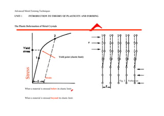
  • 1. Advanced Metal Forming Techniques UNIT-1 INTRODUCTION TO THEORY OF PLASTICITY AND FORMING The Plastic Deformation of Metal Crystals Yield point (elastic limit) Strain Fig. 3.1, Verhoeven When a material is stressed below its elastic limit: When a material is stressed beyond its elastic limit:
  • 2. Deep drawing of a cylindrical cup. (a) Before drawing; (b) after drawing
  • 3. Yielding criteria 1. Criteria for yielding (1) What is the meaning about yield criterion? In this case the stress is un-axial and this point can readily be determined. But what if there are several stress acting at a point in different direction ? ⇒ The criteria for deciding which combination of multi-axial stress will cause yielding are called criteria. (2). Theory of yield criterion- (A) Tresa criterion Yielding will occur when the maximum shear stress reaches the values of the maximum shear stress occurring under simple tension. The maximum shear stress in multi-axial stress = the maximum shear stress in simple tension max ⎩ 1 2 2 , 1 2 3 , 2 2 3 ⎭  0 1 2      
  • 4. For pure shear (k ) 1 2 0 ⇒ 1 −2 k  1 2 2 1 2 又k  1 2 2  2 k ∴k  2 ⇒For pure shear(k) state, the yielding is happened if k  2 (2)The von-Mises yield criterion 0 0 0
  • 5. Yielding begin when the octahedral shear stress reaches the octahedral shear stress at yield in simple tension. Mohr’s Circle for Plane Stress Transformation equations for plane stress. Procedure for constructing Mohr‘s circle. Stresses on an inclined element. Principal stresses and maximum shear stresses. Introduction to the stress tensor. 1
  • 6. Stress Transformation Equations σy y 1 y σ τy1x1 τyx τx1y1 x 1 y1 τxy y σ x1 σx x σx θ x σ x1 τ xy τ x1y1 τ y1x1 τ yx σy1 σx +σ y σx −σ y σx1 = + cos 2θ + τxy sin 2θ2 2 τ x1y1 = − (σ x −σ y ) sin 2θ + τxy cos 2θ 2 If we vary θ from 0° to 360°, we will get all possible values of σ x1 and τx1y1 for a given stress state. It would be useful to represent σx1 and τx1y1 as
  • 7. functions of θ in graphical form.
  • 8. To do this, we must re-write the transformation equations. σ x1 − σx +σ y = σx −σ y cos 2θ + τxy sin 2θ2 2 τ x1y1 = − (σ x −σ y ) sin 2θ + τxy cos 2θ 2 Eliminate θ by squaring both sides of each equation and adding the two equations together. σ x + σ y 2 2 σ x −σ y 2 2 − =σ x1 2 + τ x1y1 2 + τxy Define σavg and R σ x +σ y σ x −σ 2 2 σ avg = R = y 2 2 + τxy 3
  • 9. Substitue for σavg and R to get (σ x1 − σavg )2 + τx1y1 2 = R2 which is the equation for a circle with centre (σavg,0) and radius R. This circle is usually referred to as Mohr’s circle, after the German civil engineer Otto Mohr (1835-1918). He developed the graphical technique for drawing the circle in 1882. The construction of Mohr‘s circle is one of the few graphical techniques still used in engineering. It provides a simple and clear picture of an otherwise complicated analysis. 4
  • 10. Sign Convention for Mohr’s Circle y1 y (σx1 − σavg ) 2 2 = R 2 + τ x1y1 σ τy1x1 τx1y1 x1 y1 2θx1 σ θ σavg x x1 R σ x1 τ y1x1 τ x1y1 σy1 τx1y1 Notice that shear stress is plotted as positive downward. The reason for doing this is that 2θ is then positive counterclockwise, which agrees with the direction of 2θ used in the derivation of the tranformation equations and the direction of θ on the stress element. Notice that although 2θ appears in Mohr‘s circle, θ appears on the stress element. 5
  • 11. Procedure for Constructing Mohr’s Circle 1. Draw a set of coordinate axes with σx1 as abscissa (positive to the right) and τx1y1 as ordinate (positive downward). 2. Locate the centre of the circle c at the point having coordinates σx1 = σavg and τx1y1 = 0. 3. Locate point A, representing the stress conditions on the x face of the element by plotting its coordinates σx1 = σx and τx1y1 = τxy. Note that point A on the circle corresponds to θ = 0°. 4. Locate point B, representing the stress conditions on the y face of the element by plotting its coordinates σx1 = σy and τx1y1 = −τxy. Note that point B on the circle corresponds to θ = 90°. 5. Draw a line from point A to point B, a diameter of the circle passing through point c. Points A and B (representing stresses on planes at 90° to each other) are at opposite ends of the diameter (and therefore 180° apart on the circle). 6. Using point c as the centre, draw Mohr‘s circle through points A and B. This circle has radius R. (based on Gere) 6
  • 12. B σy τyx σy σx y x τxy σx B (θ=90) τxy A -τxy τyx c σ x1 R τ xy A (θ=0) σ avg σ x τ x1y1
  • 13. 7
  • 14. Stresses on an Inclined Element 1. On Mohr‘s circle, measure an angle 2θ counterclockwise from radius cA, because point A corresponds to θ = 0 and hence is the reference point from which angles are measured. 2. The angle 2θ locates the point D on the circle, which has coordinates σx1 and τx1y1. Point D represents the stresses on the x1 face of the inclined element. 3. Point E, which is diametrically opposite point D on the circle, is located at an angle 2θ + 180° from cA (and 180° from cD). Thus point E gives the stress on the y1 face of the inclined element. 4. So, as we rotate the x1y1 axes counterclockwise by an angle θ, the point on Mohr‘s circle corresponding to the x1 face moves counterclockwise through an angle 2θ. (based on Gere) 8
  • 15. B σy τyx σ y1 y τxy B (θ=90) σx x σx τxy A E (θ+90) 2θ+180 τyx -τ x1y1 σ x1 τ x1y1 c D (θ) R y 2θ y1 τy1x1σ τx1y1 x1A (θ=0) y1 E σ x1 σ x1 θ D x σ x1 τ y1x1
  • 16. τ x1y1 τ x1y1 σy1 9 Principal Stresses B σ y τyx y τxy B (θ=90) σx x σx 2θ p2 τxy τyx A σ2 c σ 1 σ x1 R 2θ p1 y σ 2A (θ=0)
  • 17. P2 σ1 θp2 P1 xθp1 σ1 τ x1y1 σ2 aximum Shear Stress B σy τyx y τxy B (θ=90) σx x σx τ min 2θs τxy τyx A c σ x1 Note carefully the y directions of the
  • 18. τ max R shear forces. σs A (θ=0) τmax σ s σ s τmax θs τmax x σs τmax τ x1y1 σs 11
  • 19. Example: The state of plane stress at a point is represented by the stress element below. Draw the Mohr‘s circle, determine the principal stresses and the maximum shear stresses, and draw the corresponding stress elements. c =σavg = σx +σ y = −80 +50 = −15 σ 1,2 = c ± R 2 2 σ 1,2 = −15 ± 69.6 R = (50 −(− 15)) 2 +(25 )2 σ1 = 54.6 MPa R = 65 2 + 25 2 = 69.6 A (θ=0) σ2 = −84.6 MPa σ2 σ c 1 σ B 50 MPa R B (θ=90) 80 MPa y 80 MPax τ max τmax = R = 69.6 MPa
  • 20. A
  • 21. 50 MPa 25tan 2θ2 = = 0.3846 y 80 −15 2θ2 = 21.0° 80 MPa x 80 MPa 2θ1 = 21.0 +180° = 201° 25 MPa θ1 =100.5° θ2 =10.5° 50 MPa A (θ=0) σ2 σ 1 σ y 2θ2 c 54.6 MPa R B (θ=90) 84.6 MPa 2θ1 o 100.5 84.6 MPa 10.5o x 2θ
  • 23. 50 MPa y 80 MPa x 80 MPa 2θ2 = 21.0° 2θs min = −(90 − 21.0) = −69.0° θs min = −34.5° 25 MPa 50 MPa τ min taking sign convention into account A (θ=0) 2θ smin y 2θ2 c 2θ σ 15 MPa 15 MPa 2θ smax 55.5o x-34.5o R B (θ=90) 15 MPa τmax 15 MPa 2θ2 = 21.0° 2θs max = 21.0 +90° =111.0° 69.6 MPa τ θ s max = 55.5° 14
  • 24. Example: The state of plane stress at a point is represented by the stress element below. Find the stresses on an element inclined at 30° clockwise and draw the corresponding stress elements. 50 MPa C (θ = -30°)y 80 MPa x 80 MPa A (θ=0) - 25 MPa 50 MPa y y1 2θ2 25.8 MPa 4.15 MPa D -60+180° x-30o 25.8 MPa D (θ = -30+90°) 4.15 MPa C x1 68.8 MPa σx1 = c – R cos(2θ2+60) σy1 = c + R cos(2θ2+60) τx1y1= -R sin (2θ2+60) σx1 = - 26 σy1 = -4 τx1y1= -69 σ B (θ=90) 2θ θ = -30° τ 2θ = -60° 15
  • 25. Principal Stresses σ1 = 54.6 MPa, σ2 = -84.6 MPa But we have forgotten about the third principal stress! Since the element is in plane stress (σz = 0), the third principal stress is zero. σ1 = 54.6 MPa σ2 = 0 MPa σ3 = -84.6 MPa This means three Mohr‘s circles can be drawn, each based on two principal stresses: σ1 and σ3 σ1 and σ2 σ2 and σ3 A (θ=0) σ 3 σ2 σ 1 σ B (θ=90) τ 16
  • 28. The stress element shown is in plane stress. B σy What is the maximum shear stress? y σx x B τxy τyx σ 3 σ2 σ1 σ x1 τ max(1,2) = σ 1 −σ 2 2 A τ max(2,3) = σ2 −σ3 2
  • 29. τyx τxy σx A = σ 2 2 overall maximum τ max(1,3) = σ1 −σ3 = σ 1 τ x1y1 2 2 18
  • 30. Introduction to the Stress Tensor y σ yy τ yx τ yz τ xy σ xx τ xy τ xz τ zy τ yx σ yy τ yz σ xx σ xx x τ τ σ τ zx τ xz zx zy zz σ zz Normal stresses on the diagonal z Shear stresses off diagaonal σ yy τ xy = τ yx, τ xz = τ zx, τ yz = τ zy The normal and shear stresses on a stress element in 3D can be assembled into a 3x3 matrix known as the stress tensor. 19
  • 31. From our analyses so far, we know that for a given stress system, it is possible to find a set of three principal stresses. We also know that if the principal stresses are acting, the shear stresses must be zero. In terms of the stress tensor, σ τ τ xx τ xy τ xz σ 1 0 0 yx σ yy τ yz 0 σ 2 0 zx τ zy σ zz 0 0 σ 3 In mathematical terms, this is the process of matrix diagonaliza-tion in which the eigenvalues of the original matrix are just the principal stresses. 20
  • 32. Example: The state of plane stress at a point is represented by the stress element below. Find the principal stresses. 50 MPa 80 MPa y 80 MPax 25 MPa 50 MPa σ x τ −80 − 25 xy M = = − 25 50 τ yx σ y We must find the eigenvalues of this matrix. Remember the general idea of eigenvalues. We are looking for values of λ such that: Ar = λr where r is a vector, and A is a matrix. Ar – λr = 0 or (A – λI) r = 0 where I is the identity matrix. For this equation to be true, either r = 0 or det (A – λI) = 0. Solving the latter equation (the ―characteristic equation‖) gives us the eigenvalues λ1 and λ2. 21
  • 33. −80 –λ − 25 = 0det − 25 50 −λ (−80 −λ)(50 −λ) −(−25)(−25) = 0 λ2 +30λ − 4625 = 0 So, the principal stresses are –84.6 MPa and λ = −84.6, 54.6 54.6 MPa, as before. Knowing the eigenvalues, we can find the eigenvectors. These can be used to find the angles at which the principal stresses act. To find the eigenvectors, we substitute the eigenvalues into the equation (A – λI ) r = 0 one at a time and solve for r. −80 − λ − 25 x 0 = − 25 050 −λ y −80 −54.6 − 25 x 0 = − 25 50 −54.6 0y −134.6 − 25 x 0 = − 25 − 4.64 0 y x = −0.186 y −0.186 is one eigenvector.1 22
  • 34. −80 −λ − 25 x 0 = − 25 50 −λ y 0 −80 −(−84.6) − 25 x 0 = − 25 50 −(−84.6) 0y 4.6 −25 x 0 = −25 134.6 0 y x = 5.388 y 5.388 is the other eigenvector. 1 Before finding the angles at which the principal stresses act, we can check to see if the eigenvectors are correct. 54.6 0 −0.186 5.388 −80 −25 CD = 0 −84.6 = 1 1 M = − 25 50 D = C−1 M C C −1 = 1 AT where A = matrix of co - factorsdet C −1 −0.179 0.967 C = 0.179 0.033
  • 35.
  • 36. −0.179 0.967−80 − 25 −0.186 5.388 54.6 0 D = 0.179 0.033 − 25 50 1 1 = 0 −84.6 To find the angles, we must calculate the unit eigenvectors: −0.186 −0.183 5.388 0.938 → → 1 0.983 1 0.183 And then assemble them into a rotation matrix R so that det R = +1. 0.983 −0.183 det R = (0.983)(0.983) −(0.183)(−0.183) =1R = 0.183 0.983 The rotation matrix has the form Cosθ −sinθ ′ T D = R M RR = cosθSinθ So θ = 10.5°, as we found earlier for one of the principal angles. 24
  • 37. Using the rotation angle of 10.5°, the matrix M (representing the original stress state of the element) can be transformed to matrix D’ (representing the principal stress state). D′ = RT M R ′ 0.983 0.183 −80 D = −0.183 0.983 −25 ′ −84.6 0 D = 0 54.6 y 54.6 MPa o 84.6 MPa 100.5 84.6 MPa x10.5o −25 0.983 −0.183 50 0.183 0.983 So, the transformation equations, Mohr‘s circle, and eigenvectors all give the same result for the principal stress element. 54.6 MPa
  • 38. 25 Powder metallurgy (PM) is the production and utilization of metal powders. Powders are defined as particles that are usually less than 1000 nm (1 mm) in size. Most of the metal particles used in PM are in the range of 5 to 200 mm (0.2 to 7.9 mils). To put this in context, a human hair is typically in the 100 mm (3.9 mils) range. The history of PM has already been outlined in the article ―History of Powder Metallurgy‖ in this Volume. This article reviews the various segments of the PM process from powder pro-duction and powder processing through to the characterization of the materials and their prop-erties. It will cover processing methods for con- solidating metal powders including options for processing to full density. Powders have a high ratio of surface area to volume and this is taken advantage of in the use of metal powders as catalysts or in various chemical and metallurgical reactions. While this article focuses on the use of powders to make functional engineering components, many metal powders are used in their particulate form. This aspect of PM is covered in the arti-cle ―Specialty Applications of Metal Powders‖ in this Volume. Powder technologies are exciting to engi-neers because processing options permit the selective placement of phases or pores to tailor the component for the application. The capabil-ity of press and sinter processing or metal injec-tion molding (MIM) processing to replicate parts in high volumes is very attractive to design engineers. The ability to fabricate complex shapes to final size and shape or to near-net shape is particularly valuable. Powder metal-lurgy offers the potential to do this in high volumes and also for applications where the volumes are not so large. The three main reasons for using PM are eco-nomic, uniqueness, and captive applications, as shown in Fig. 1 (Ref 1). For some applications that require high volumes of parts with high precision, cost is the overarching factor. A good example of this segment is parts for the auto-motive industry (where approximately 70% of
  • 39. ferrous PM structural parts are used). Powder metallurgy parts are used in engine, transmis-sion, and chassis applications. Sometimes it is a unique microstructure or property that leads to the use of PM processing: for example, porous filters, self-lubricating bearings, dispersion-strengthened alloys, functionally graded materi-als (e.g., titanium-hydroxyapatite), and cutting tools from tungsten carbide or diamond com-posites. Captive applications of PM include materials that are difficult to process by other techniques, such as refractory metals and reac-tive metals. Other examples in this category are special compounds such as molybdenum disili-cide and titanium aluminide, or amorphous metals. The metal powder industry is a recognized metal forming technology that competes dir-ectly with other metalworking practices such as casting, forging, stamping (fine blanking),
  • 40. Fig. 1 Three main reasons for choosing powder metallurgy shown in the form of a Venn diagram. The intersection of the three circles represents an ideal area for applying PM techniques. Source: Ref 1
  • 41. and screw machining. The industry comprises powder suppliers and parts makers, plus the companies that supply the mixing equipment, powder handling equipment, compacting presses, sintering furnaces, and so forth. Powder metallurgy processing offers many advantages. The PM process is material and energy efficient compared with other metal forming technologies. Powder metallurgy is cost effective for making complex- shaped parts and minimizes the need for machining. A wide range of engineered materials is available, and through appropriate material and process selec-tion the required microstructure may be devel-oped in the material. Powder metallurgy parts have good surface finish and they may be heat treated to increase strength or wear resistance. The PM process provides part-to-part reproduc-ibility and is suited to moderate-to-high volume production. Where necessary, controlled micro-porosity can be provided for self-lubrication or filtration. While dimensional precision is good, it typically does not match that of machined parts. In the case of ferrous PM parts, they have lower ductility and reduced impact resistance compared with wrought steels. The majority of PM parts are porous and con-sideration must be given to this when performing finishing operations. Metal Powders Metal powders come in many different shapes and sizes (Fig. 2). Their shape, size, and size dis-tribution depend on the manner in which they were produced. Metal powder production is cov-ered in depth in various articles in the Section, ―Metal Powder Production‖ in this Volume. There are three main methods of powder production: Mechanical, including machining, milling, and mechanical alloying Chemical, including electrolytic deposition, decomposition of a solid by a gas, thermal Introduction to Powder Metallurgy
  • 42. 5 μm 5 μm Fig. 2 Example of the different particle shapes possible with metal powders
  • 43. limited plasticity. Rigid die compaction is not suitable for consolidating such powders, and they must be processed by other means such as hot pressing, extrusion, or hot isostatic pressing (HIP), described subsequently in this article. Highly reactive metal powders are also not suitable for rigid die compaction. They generally need to be vacuum hot pressed, or encapsulated and extruded, or HIPed. Rigid die compacted parts and MIM parts are thermally treated to increase their strength in a process known as sintering. The parts are heated, generally in a reducing atmosphere, to a temperature that is below the melting point of the primary constituent of the material, in order to form metallurgical bonds between the compacted metal powder particles. Sintering is a ―shrinkage‖ process. The system tries to reduce its overall surface area via various diffu-sion processes. Metallurgical bonds (micro- decomposition, precipitation from a liquid, precipitation from a gas, solid-solid reactive synthesis Physical, including atomization techniques Most metals are available in powder form. Some may be made by many different methods, while for others only a few options are possible. The characteristics of the powder are deter-mined by the method by which it is produced. The shape, size, size distribution, surface area, apparent density, flow, angle of repose, com- pressibility, and green strength depend on the powder production method. In-depth coverage of the sampling and testing of metal powders is presented in the articles in the Section ―Metal Powder Characterization‖ in this Volume. Powder Processing For the production of PM parts in high volumes, compaction is carried out in rigid dies. In most instances, the metallic powders are mixed with a lubricant (e.g., ethylene bis-stearamide) to reduce interparticle friction dur- ing compaction and to facilitate ejection of the compacted parts by reducing friction at the die-wall and core-rod interfaces. The metal powders may be elemental pow-ders; mixtures of elemental powders; or mix-tures of elemental powders with master alloys or ferroalloys, prealloys, diffusion alloys, or hybrid alloys. See the article ―Ferrous Powder Metallurgy Materials‖ in this Volume for an in-depth review of the alloying methods used in ferrous PM. A consequence of the various alloying methods available is that only the PM materials made from prealloyed powders are chemically homogeneous. The other alloying methods can result in chemically inhomoge-neous materials. The hardenability is determined by the local chemical composition, and the resulting microstructures are generally quite complex. Chemical analysis can be a challenge due to the inhomogeneous nature of the materi-als. Guidelines for sample preparation for the
  • 44. chemical analysis of the metallic elements in PM materials are provided in MPIF Standard 67 (Ref 2). Complex, multilevel PM parts compacted in rigid dies will not have the same green density throughout. While the objective is gen-erally to achieve a density as uniform as pos-sible throughout the compacted part, taller parts and parts with multiple levels are subject to the presence of density differences between adjacent regions. This is due to frictional effects and compacting tool deflections. Taller parts will have a neutral zone or density line— the region of the compact that has experienced the least relative movement of powder. The position of the neutral zone may be adjusted by varying the pressure exerted by the upper and lower punches. Compaction in rigid dies is limited to part shapes that can be ejected from the die cavity. Parts with undercuts, reverse tapers, threads, and so forth, are not generally practical. Such features are formed by postsintering machining operations. There are two main types of compacting press: mechanical and hydraulic. Some hybrid presses offer features of both. A detailed treat-ment of compaction is provided in the Section ―Metal Powder Compaction‖ in this Volume. Some PM parts are molded (shaped) rather than compacted. Fine-particle-size metal pow-ders (5 to 20 mm, or 0.2 to 0.8 mils) are mixed with binders and plasticizers and processed to form a feedstock for MIM. Molding is per-formed using machines similar to those used for plastic injection molding. Shrinkage during the subsequent sintering operation is extensive (15 to 20%) due to the fine-particle-size pow-ders used and the high sintering temperatures. Because the parts are molded and not com-pacted, they do not contain density gradients that lead to distortion or problems with dimen-sional control. The process makes complex-shaped, small-to-medium sized PM parts with high relative densities. Some metal powders are not very compress-ible. The powder particles are hard and have
  • 45. scopic weldments) form between adjacent metal particles (after oxides have been reduced on the surface of the powder particles), pore surfaces become less irregularly shaped, and larger pores grow at the expense of the smaller pores. Sintering is generally carried out using continuous mesh-belt furnaces. For higher temperatures (1150 C, or 2100 F), pusher, roller hearth, or walking-beam furnaces may be used. Batch furnace processing is used for special applications (e.g., pressure-assisted sintering). More information on sintering may be found in the Section ―Sintering Basics‖ in this Volume. Powder Metallurgy Material Properties The majority of PM parts contain pores (see options for processing metal powders to full density later in this article). This is an advan-tage when metal powders are used to make self-lubricating bearings in which the surface-connected pores of the parts are impregnated with oil. When the bearing surface heats up due to frictional heat, oil is released from the pores. When the bearing cools, the oil is sucked back into the pore channels by capillary action. The porosity in PM parts has an effect on the physical, mechanical, magnetic, thermal, wear, and corrosion properties of the parts. Thermophysical properties of sintered steels, in particular their coefficient of thermal expan-sion and their thermal conductivity, are needed when designing parts and when modeling heat treatment processes. Opinions differ in the PM community as to the effect of density on these properties. Danninger has shown, how-ever, that the coefficient of thermal expansion up to 1000 C (1832 F), measured through dilatometry, is virtually independent of porosity (density) over a density range from 5.97 to 7.53 g/cm3 (Ref 3). In addition, thermal con- ductivity was determined in the same tempera-ture range by using laser flash to measure thermal diffusivity, and specific heat, and then
  • 46. Powder Metallurgy Methods and Applications / 11 the thermal conductivity was calculated from these parameters and the density in accordance with: a ¼ l rCp (Eq 1) where a is thermal diffusivity, l is thermal conductivity, r is density, and Cp is specific heat at constant pressure. Thermal conductivity was shown to depend on density. The effect of porosity in the tech-nically relevant density range was, however, slightly less pronounced than the effect exerted by the alloying elements; specifically, the vari-ation observed between different standard PM steel grades in the low-to-medium temperature range. Both thermophysical properties are, therefore, significantly less influenced by poros-ity than by chemical composition. Powder met-allurgy steels are more similar to wrought steels than was generally assumed. The elastic constants are also of interest to the design engineer. Young‘s modulus, Pois-son‘s ratio, and the shear modulus are related according to: E ¼ 2Gð1 þ nÞ (Eq 2) where E is Young‘s modulus, G is shear modulus, and n is Poisson‘s ratio. E and n are determined by resonant frequency and G is calculated from Eq 2. Beiss (Ref 4) has shown that: E ¼ E0ðr=r0Þm (Eq 3) where E0 is the Young‘s modulus of the pore-free material, r is the density of the material, r0 is the density of the pore-free material, and the exponent m depends on the pore morphology and varies between 2.5 and 4.5. Nevertheless, over the density range of interest for ferrous PM structural materials, 6.4 to 7.4 g/cm3 , Young‘s modulus is essentially a linear function of density (Fig. 3) (Ref 5).
  • 47. Poisson‘s ratio is a weak function of density, and for ferrous PM structural steels it can be taken as 0.27 ± 0.02. The mechanical properties of PM materials are a function of density: P=P0 ¼ ðr=r0Þm (Eq 4) where, P is the property of interest, P0 the value for the pore-free material, r is the density of the material, r0 is the density of the pore-free material, and m is an exponent the value of which depends on a given property (Fig. 4) (Ref 6–7). While tensile strength increases in a linear fashion as density increases, tensile ductility is more dependent on reducing the level of porosity. Fatigue performance is even more influenced by density with an exponent m of between 3.5 and 4.5. Impact energy is the most dependent on density, with an expo-nent m of approximately 12. Magnetic properties of ferrous PM materials are affected by density. Induction and per-meability increase as the density is increased. Permeability and coercive field strength are structure-sensitive properties that are degraded by the presence of impurities. The sintering con-ditions are extremely important to keep carbon, nitrogen, and oxygen contents to low levels (C = 0.03 wt% max; N = 0.01 wt% max; and O = 0.10 wt% max). Residual stresses from operations such as sizing, machining, or shot peening degrade the magnetic properties. The properties can be restored through an annealing treatment. Processing Options to Consolidate Metal Powders There are three basic approaches to the con-solidation of metal powders, as shown in Fig. 5 (Ref 8). Pressure-based compaction establishes density via the compaction process then sinters
  • 48. to develop strength in the compacts. Rigid die compaction falls into this category and is the most cost-effective method for the high-volume production of PM structural parts. In order for this method to be viable, the metal powders need an irregular shape and good flow character-istics, they must be compressible, and they must have good ―green‖ strength. (Green is the term used to describe an as-pressed compact.) Extremely hard particles with a spherical shape are not appropriate for use in rigid die compac-tion. Compaction takes place at high pressure in confined dies (the dies are generally made from cold work tool steel or cemented carbide). Compacting pressures for ferrous powders are generally in the range from 400 to 700 MPa (60 to 100 ksi), from 100 to 400 MPa (14.5 to 60 ksi) for aluminum and aluminum alloy pow-ders, and approximately 400 MPa (60 ksi) for copper and copper-alloy powders. The green density increases as the compact-ing pressure is increased and levels out at higher compacting pressures. Powder particles work harden as the result of plastic deformation and it requires higher pressures to cause further plastic flow. In addition, the lubricant that is typically admixed to aid particle rearrangement and to reduce the fictional forces between the powder and the compacting tools eventually has no place to go because all the voids between particles have been closed—either by metal flow or by the presence of lubricant. More lubricant is beneficial at lower compact-ing pressures, but there is a transition point at which the additional lubricant impedes further densification (Fig. 6) (Ref 9). Warm compaction processing was developed to overcome the compressibility constraints of rigid-die compaction (Ref 10). The powder mixture and the compacting tools are heated 52 7.5 51 7.4 Young‘smodulus,GPa 50 7.3 psi6 49 7.1 Young‘smod ulus,10 48 7.0 47 6.8 46 6.7 45 6.5 44 6.4 6.4 6.6 6.8 7.0 7.2 7.4 7.6
  • 49. Sintered density, g/cm3 Fig. 3 Young‘s modulus as a function of sintered density. Data from Ref 5 Fig. 4 Effect of density on mechanical and physical properties of PM materials. Source: Ref 6
  • 50. 12 / Introduction to Powder Metallurgy Fig. 5 Three basic approaches to the consolidation of metal powders. Source: Ref 8 to approximately 120 C (250 F) and the powder is compacted in a single press stroke. Green densities of up to 7.3 g/cm3 are possible with highly compressible ferrous powders. This is approximately 98% of the pore-free density of the powder mixture being compacted (The pore-free density of the powder mixture is the green density that could be reached if all the porosity was removed from the material. It can be calculated for any mixture based on the density and the amount of each constituent in the mixture and the volume they would occupy in the pore-free condition.) Special lubricants and binder-treated premixes were developed for warm compaction. The efficiency of the special lubricant enabled it to be reduced to 0.6 wt% from the 0.8 wt% more typically used for rigid-die compaction: the pore-free density increases by 0.1 g/cm3 for each 0.2 wt% reduc-tion in the amount of the admixed lubricant. Examples of warm compacted parts are shown in Fig. 7. More recently, warm-die compaction has been introduced. In this instance, only the com-pacting tooling is heated (the powder is not heated). The optimal die temperature varies according to the specific lubrication system being used. The die temperature is set so that the surface temperature of the green compacts reaches the desired range for the lubricant sys-tem in question. Warm-die compaction is ideal for small-to-medium size parts that weigh less than 700 g (1.5 lb), are up to 32 mm (1.3 in.) high, and have wall thicknesses of up to 19 mm (0.75 in.). For larger parts warm com-paction processing is required. Green densities of 7.45 g/cm3 have been reached using warm-
  • 51. Contacting pressure, ksi 58.0 72.5 87.0 101.5 116.0 130. 5 7. 4 7. 3 3 7. 2 g/c m 7. 1 Transi tion pressure density, 7. 0 Green 6. 9 Atomi zed iron 6. 8 6. 7 500 600 700 800 900400 Compacting pressure, MPa 0.5% Zn St 0.75% Zn St 1.0% Zn St
  • 52. Fig. 6 Effect of lubricant content on the compressibility of metal powders. Source: Ref 9 Fig. 7 Examples of warm compacted PM parts. (a) Torque converter hub. Courtesy of Chicago Powder Metal Products. (b) Transmission output shaft hub. Courtesy of GKN Sinter Metals. (c) Hand tool parts. Courtesy of PoriteTaiwan Co. Ltd. die compaction with lubricant additions of approximately 0.3 wt% (Ref 11). In sintering-based densification, the shape of the component is formed in a molding oper-ation (e.g., MIM) and sintering is enhanced by the use of high temperatures and fine-particle-size powders. While extensive shrinkage occurs during sintering, it is essentially isotropic in nature so that good tolerance can still be achieved. Metal powder loading in the feed-stock used for MIM is approximately 60%. The binders and plasticizers added to make the mixture moldable must be removed prior to final sintering. This ―debinding‖ step is the rate-controlling phase of the MIM process. Other sintering-based densification processes that involve the molding or shaping of powders are slip casting and tape casting. Hybrid Densification. For some materials, a hybrid densification process is used in which pressure and temperature are applied at the same time. As mentioned previously, some powders are not suitable for rigid-die compaction; they are too hard, are spherical in shape, or are too reactive. In this instance, processes such as pow- der extrusion (typically after encapsulation) or HIP are used. Hot pressing (often in vacuum) or spark sintering may also be used. Processing to Full Density
  • 53. Options for processing metal powders to full density are mapped in Fig. 8 (Ref 12). The ver-tical axis relates to relative stress (the applied pressure divided by the in situ yield strength of the material) and the horizontal axis relative temperature (based on the melting temperature of the material). Full-density processing requires the simulta-neous application of pressure and temperature. The approach works because most materials soften as temperature is increased. They also become more ductile and deform with less work hardening. The processing options fall into the following categories: Low-stress processes that operate at high temperatures and are dominated by diffusion processes (e.g., liquid-phase sintering) Processes that apply intermediate stress levels and operate at intermediate temperatures and rely on diffusional creep processes (e.g., hot pressing or HIP) High-stress routes that operate at high strain rates and lower temperatures (powder forging or extrusion) Routes that achieve high density via the application of ultrahigh-stress at ambient temperature (explosive compaction) Liquid-phase sintering results in a composite microstructure that consists of a skeleton of a high-melting- temperature phase in a matrix of a solidified liquid—for example, W-Ni-Fe heavy alloys, WC-Co cemented carbides.
  • 54. Hot pressing is performed in a rigid die using uniaxially applied pressure: it is a low-strain-rate process. Graphite dies may be used, in which case induction heating may be employed. Hot pressing cycle times are slow compared with rigid-die compaction. Vacuum is sometimes used to minimize contamination of the compact. Diamond-metal-composite cutting tools are often hot pressed. Spark sintering is a process related to hot pressing. In spark sintering, direct resistance heating is applied to the punches, die, and powder mass during consolidation. Hot isostatic pressing applies pressure from all directions simultaneously. In order to estab-lish a pressure differential, powders must be processed to the point where they have no surface-connected, interconnected porosity, or they need to be encapsulated prior to the HIP process. Prior to HIP, a container is filled with powder and heated under vacuum to remove volatile contaminants. After evacuation and degassing, the container is sealed. The con-tainer may be fabricated from any material that is soft and deformable at the consolidation tem- perature, for example, glass, steel or stainless steel (the choice depends on compatibility with the powder that is being compacted). A HIP vessel is illustrated in Fig. 9 and the sequence used to make a HIPed part is shown in Fig. 10 (Ref 13). Fig. 8 Options for processing metal powders to full density. Source: Ref 12 Vacuum sintering then backfilling the sin-tering furnace with pressurized gas to assist final densification is employed in sinter-HIP processing (a pressure-assisted sintering pro-cess). A typical cycle is shown schematically in Fig. 11 (Ref 14).
  • 55. Fig. 9 (a) Typical hot isostatic pressing (HIP) vessel. (b) Schematic of the wire-wound unit. Courtesy of Avure Technologies. Source: Ref 13 Powder forging bridges the gap between con-ventional pressing and sintering and wrought steel technology. The process is illustrated schematically in Fig. 12 (Ref 15). A PM pre-form is typically compacted, sintered, and then reheated before being forged in a single stroke in confined dies. A detailed review of the pow-der forging of ferrous materials is given in the Section ―Powder Metallurgy Carbon and Low-Alloy Steels‖ in this Volume. Extrusion is used to make some PM tool steels. These materials have better properties than similar wrought tool steels because they contain a finer and more uniform dispersion of carbides compared with the wrought tool steels. In the latter, the carbides are often banded and in the form of stringers due to the rolling pro-cess used to make them, as shown in Fig. 13 (Ref 16).
  • 56. Freeform Fabrication Thermal spraying of nickel-base and cobalt-base alloy powders to form wear-resistant coat-ings has been practiced for many years. Spray forming is a consolidation process that captures a spray of molten metal or alloy droplets on a moving substrate (Ref 17). Figure 14 illustrates billet formation in a vertical mode by spray forming. The process can be used to form bil-lets, strip, and thick-walled tubing. The term additive manufacturing of metals is used to describe freeform processes that offer the possibility to produce complex-shaped PM parts without the design constraints of tradi-tional manufacturing routes (Ref 18). The pro-cess relies on the transfer of a digital file to a machine that then builds the three-dimensional component layer by layer from a metal powder using a laser or an electron beam to fuse the particles together. Schematic illustrations of powder-bed and powder-fed systems are shown in Fig. 15 (Ref 19). Finishing Operations While PM is considered a net or near-net shaping process, many PM parts require finishing Fig. 11 Schematic of pressure-assisted sintering process cycle. Source: Ref 14
  • 57. operations. Sometimes parts need closer tolerances than can be held during the pressing and sintering operation; they can be sized to reduce their dimensional variability. The surface-connected, interconnected poros-ity in PM parts can be impregnated with oil, and this is the basis for self-lubricating bearings (Ref 20). Conventional bearings can absorb from 10 to 30% by volume of oil. Pressure tightness can be achieved in PM parts by sealing the surface-connected porosity by resin impregnation. Vacuum processing is generally used to impregnate the PM parts. In addition to developing pressure tightness, resin impregnation of PM parts permits plating (oth-erwise, plating solutions would be trapped in the surface-connected pores). Resin impregna-tion significantly improves the drillability of PM parts, as shown in Fig. 16 (Ref 21). Machining parameters for PM parts are dif-ferent from those used for castings or wrought components. The PM materials contain pores. Depending on the hardness of the material, the material in the vicinity of the cutting tool will densify to a greater or lesser extent. As the amount of porosity decreases, PM parts machine more like cast or wrought parts with a similar microstructure. Machinability aids such as manganese sulfide (MnS) may be added to the PM material prior to compaction to enhance the machinability of the PM parts. Powder metallurgy parts may be turned, milled, drilled, tapped, and ground. Machinabil-ity depends on the density and the microstructure of the material. For a PM material of a given density and microstructure, the machinability will depend on the type of cutting operation being performed, the cutting tool material, and the feeds and speeds being used. Examination of the cutting tool is one of the keys to understanding what is happening during the machining process. Moving to a condition of abrasive wear will lead to greater consis-tency and predictability in the machining oper-ation. A statistical approach to evaluating the To preheat furnace Eject from die (a) Pre-HIP filled can weighing 2050 kg (4520 lb). (b) Post-HIP. (c) Heat treated and sonic machined HIPed part. Courtesy of Carpenter Technologies. Source: Ref 13 Fig. 12 Schematic of the powder forging process. Source: Ref 15
  • 58. Powder Metallurgy Methods and Applications / 15 Fig. 13 Extruded T15 tool steel. (a) Wrought. (b) PM. Notice the bands of carbides in the wrought tool steel compared with the uniform dispersion of fine carbides in the PM tool steel. Source: Ref 16
  • 59. Induction heated ladle Particle injector (optional) Atomizer (nitrogen) Round, spray-deposited billet Spray chamber Exhaust Fig. 14 Billet formation in a vertical mode by spray forming. Source: Ref 17 ―Sweet spot‖ Robust process, able to accept variation Mac hinin g proces s ―Safe zone‖ Noncatastr ophic, consistent tool performanc e
  • 60. Fig. 15 Schematic illustrations of (a) powder-bed and (b) powder-fed additive manufacturing. Source: Ref 18 Fig. 16 Relative drillability of various PM materials. Source: Ref 21 data is extremely beneficial. Abrasive wear is without the tool failing in a catastrophic man- the common and natural mechanism of wear ner. This is the ―safe zone‖ for machining, during machining—it is the desired mechanism. Fig. 17 (Ref 22). There are combinations of machining para- Ferrous PM parts may be heat treated to meters (cutting tool, feeds, speeds, etc.) that improve their hardness, strength, and wear resis- result in consistent machining performance tance. Oil quenching and tempering may be used
  • 61. Fig. 17 ―Sweet spot‖ for machinability. Source: Ref 22 for neutral hardening. Induction hardening of PM parts is also possible. Gaseous carburizing, nitriding, carbonitriding, and nitrocarburizing processes are applicable. Care is required with ferrous parts at densities below 7.1 g/cm3 (0.26 lb/in.3 ), because gas penetration to the core of the part can lead to loss of toughness. The use of salt baths is to be avoided because the salt would penetrate the surface-connected pores and lead to subsequent corrosion problems. Microin-dentation hardness testing is used to determine the effective case depth of surface-hardened PM parts (Ref 23). Where there is a clear difference between the hardened layer and the rest of the part, such as with an induction-hardened part, a metallographic estimate may be made of the case depth (Ref 24). Powder metallurgy parts are often tumbled in an abrasive medium in rotating barrels or agitated in vibrating tubs to clean them and remove burrs. They are generally resin or oil impregnated before tumbling to minimize water absorption. Rust inhibitors should be added to the water. Parts may be spun dry or heated to dry. Ferrous PM parts may be furnace blackened (steam oxide treated) for indoor corrosion resis-tance. Afterward, they may be oil dipped for
  • 62. 16 / Introduction to Powder Metallurgy color as well as slightly greater corrosion resis-tance (a dry film oil is particularly suitable). Steam treating forms a coating of magnetite (Fe3O4) in the surface-connected pores. Parts are heated to 480 to 570 C (896 to 1060 F) and exposed to superheated steam under pres-sure. This improves the wear resistance of fer-rous PM parts and improves their compressive strength. It does, however, degrade tensile prop-erties (Ref 25). All types of plating processes may be applied to PM parts, but the parts should have surface-connected porosity sealed by resin impregna-tion prior to plating. Electroless nickel plating is applicable to nonimpregnated PM parts. Most conventional welding methods are applicable to PM parts (Ref 26). Care must be taken to avoid residual lubricants, quench oils, machining coolants, plating solutions, impregnat-ing materials, cleaning or tumbling agents, and free graphite or residual ash. An example of a PM weldment is shown in Fig. 18 (Ref 27). Care must be taken with lower-density PM parts, particularly during fusion welding. Subsequent solidification causes high stresses that often result in cracks. Furnace brazing can be used to join PM parts. When choosing a brazing alloy, the capil-larity of the pores imposes a special condition. Standard brazing compounds will infiltrate the adjacent pores, leaving insufficient material to form a sound brazed joint. A special brazing sys-tem has been developed for PM materials that restricts brazing alloy penetration to the imme-diately adjacent areas of the part (Ref 28). An example of a brazed carrier and one-way rocker clutch assembly is provided in Fig. 19. Applications of Powder Metallurgy Parts The following examples have been selected to illustrate the wide diversity of the parts made
  • 63. using PM processes. They are taken from parts that have won awards at the MPIF Design Excellence Competition, which is held annually to highlight the advances made in PM part pro-duction (Ref 29). The carrier and one-way rocker clutch assembly shown in Fig. 19 are used in the Ford Super Duty TorqShift six-speed automatic transmission. The hybrid assembly contains five PM steel parts weighing a total of 7.7 kg (17 lb). The sinter-brazed subassembly consists of four multilevel PM parts, of which three parts (cage, spider, and carrier plate) are made to a density of 6.8 g/cm3 . In addition, there are 17 compacted brazing pellets. The rocker plate is sinter hardened during the sinter-brazing phase and has a density of 7.0 g/cm3 . The assembly also has a doubled-pressed and double-sintered cam plate made to 7.3 g/cm3 density with an ultimate tensile strength of 1170 MPa (170 ksi) and a mean tempered hard-ness exceeding 40 HRC. To form the parts and maintain precision tolerances, innovative tooling was developed and used in conjunction with unconventional press motions. Ford subjected the assembly to stringent durability testing: ulti-mate torsional torque loading at a minimum of 10.8 kN m (7970 lbf.ft) and fatigue testing at a minimum of 299,000 cycles at 2.3 kN m (1700 lbf.ft). The application provided an esti-mated 20% cost savings over competing pro-cesses and represents a new era in the scope and size of PM parts. A ball-ramp actuator consisting of a sector gear and a fixed ring is illustrated in Fig. 20. The actu-ator applies torque to the front wheels in the BMW high-performance X-Drive transfer case that goes into various BMW platforms. Warm compacted from a hybrid low-alloy steel, the parts have a density of 7.2 g/cm3 in the ball ramps and 7.0 g/cm3 between ramps and on teeth, a typical tensile strength of 1330 MPa (190 ksi), typical yield strength of 1144 MPa (166 ksi), and a sur-face hardness of 50 HRC on the ball ramp surface. The parts replaced forged components that had
  • 64. been used in an earlier transfer case design and provided 35% cost savings over the forgings. The variable valve timing (VVT) rotor shown in Fig. 21 consists of an assembly of a PM steel rotor and an adapter. The parts are joined by an adhesive, which joins them during the machining of cross-holes and other features on the inside diameter, and seals the joint bet-ween them. The assembly, used in a Chrysler Fig. 19 Carrier and one-way rocker clutch assembly. GKN Sinter Metals LLC, courtesy of MPIF Fig. 20 Sector gear and fixed ring. Cloyes Gear Products Inc., courtesy of MPIF 409 Cb wrought tube 409 Cb wrought tube
  • 65. V-6 engine, is mounted to the engine camshaft. Formed to a density of 6.8 g/cm3 , the rotor has an ultimate tensile strength of 415 MPa (60 ksi), yield strength of 380 MPa (55 ksi), and a 160 MPa (23 ksi) fatigue limit. The adapter is formed to a density of 6.9 g/cm3 , has a minimum ultimate tensile strength of 400 MPa (58 ksi), and has a yield strength of 365 MPa (53 ksi). After sizing and grinding, there is no other machining performed on the rotor. The adapter is not machined prior to assembly and is made to net shape with vertical slots for oil feeding. The cus-tomer, however, machines the cross-holes for the oil feed. Figure 22 shows a complex PM steel two-stage helical gear and spur pinion used in a power lift-gate actuator. Made to a nominal density of 6.85 g/cm3 , the combined helical gear-and-pinion design features precision jour- nals for precise orientation in the actuator assembly. The part has a tensile strength of 450 MPa (65 ksi) and yield strength of 380 MPa (55 ksi). The precise elemental gear data tolerances enable quiet gear performance, decreasing noise, vibration, and harshness. Four metal injection molded (MIM) parts (a blank discharge check, stop discharge check valve, valve discharge check, and CRV spring seat) that go into a device that controls fuel flow in gasoline direct-injection pumps are shown in Fig. 23. Three of the parts are made of 440C stainless steel, while the fourth is Fig. 22 Helical gear and spur pinion. Capstan Atlantic, courtesy of MPIF
  • 66. made of 17-4 PH. The extremely complex geometry of the blank discharge check, with the intercrossing of holes, required tooling with six side cores, three of which move at different timings. The parts have a minimum density of 7.65 g/cm3 , an ultimate tensile strength of 480 MPa (70 ksi), yield strength of 150 MPa (22 ksi), an elongation of 45%, and a 100 HRB maximum hardness. This design was judged by the fabricator to be perhaps the most complex high-volume part ever made by MIM. The customer realized cost savings of close to 35%, while the pump performance was improved by modifying the geometry of the holes to enhance flow dynamics, with the result being a 10 to 20% fuel economy boost. Another automotive application is shown in Fig. 24. It is a PM aluminum camshaft-bearing cap used in GM‘s high-feature V6 engine. Designed originally for PM, the caps—two of which go into each engine—operate in engines that go into various GM brands, including the Cadillac CTS, SRX, and CTX; Buick LaCrosse and Rendezvous; and Saab 9-3. It is the first dual overhead cam engine using a single cap across both camshafts. The cap maintains the camshaft position, radially and axially, while providing integral oil channels for cam lubrica- tion and hydraulic control of the variable cam timing (VCT) system. Made to a net shape, the multiple-level part has a tensile strength of 117 MPa (17 ksi) and a hardness range of 85 to 90 HRH. Choosing PM over an alterna- tive manufacturing process, such as die casting, provided an estimated 50% cost saving by elim-inating preassembly machining steps. The PM caps require only one line-boring step during installation. In addition to being used in automotive appli-cations, PM parts are also chosen for lawn and garden use. The parking/emergency brake piston shown in Fig. 25 is used in hydraulic transmis-sions in zero-turn-radius lawn maintenance equipment. Made from an FC-0208 iron-copper steel, the piston is compacted with three features on top and six on the bottom, using two upper and three lower punches plus a die shelf. The piston has a density of 6.9 g/cm3 , a tensile
  • 67. strength of 565 MPa (82 ksi), yield strength of 450 MPa (65 ksi), and a hardness of 80 HRB before steam oxide treatment. The part is an original design for PM, because its shape makes it impractical for traditional metal cutting meth-ods. It is pressed and sintered to net shape, requiring no postsintering machining operations. An example of small, intricate PM parts is provided in Fig. 26. The three parts—bracket, slide, and removable drop-in hook—used in the Damon 3MX self-ligation orthodontic tooth-positioning system are made via MIM proces-sing. One bracket and one slide go on each tooth, with the hook an option for approximately 5% of the teeth. The very tiny, intricate parts are made by MIM from 17-4 PH stainless steel pow-der to a density of 7.5 g/cm3 . They have impres-sive physical properties: a tensile strength of 1190 MPa (173 ksi) and yield strength of 1090 MPa (158 ksi). All of the parts are made to a net shape. The customer tumble polishes them and performs a brazing operation before assembly. Fig. 25 Brake piston for hydraulic transmission used in zero-turn-radius lawn maintenance equipment. Lovejoy Powder Metal Group, courtesy of MPIF
  • 68. 18 / Introduction to Powder Metallurgy
  • 69. Another example of MIM parts is provided in Fig. 27. It is a high-compression jaw used in laparoscopic vessel fusion. The jaw design has top and bottom jaws, an anchor, and an I-beam. All four components are made from 17-4 PH metal powder and have as-sintered densities greater than 7.6 g/cm3 . The parts have very thin walls and highly complex geometries, making them difficult to manufacture economically by any other technology. Top and bottom jaws pivot at the lobes that provide the fulcrum for the assembly. The cutting mechanism on the laparoscopic device is in the shape of an I-beam. Very high compression is maintained as the blade is advanced from the proximal to the distal end of the jaw. The SurgRx system incorporates smart electrotechnology in a high-compression jaw design to provide rapid vessel fusion without thermal effects. A sound tube used in a hearing aid, the func-tion of which is to enhance sound frequency and improve hearing, is shown in Fig. 28. Fab-ricated via MIM using 316 stainless steel, the highly complex part achieves all its features in the as-sintered condition, with only glass-bead blasting for a better finish performed as a secondary operation. The tube has a minimum density of 7.65 g/cm3 , an ultimate tensile strength of 480 MPa (70 ksi), yield strength of 150 MPa (22 ksi), an elongation of 45%, and a hardness of 100 HRB max. An original design for MIM, it is estimated the part provides 20% cost savings over competing forming processes. A three-piece assembly (nozzle interface, outer nozzle, and metal collar) that goes into high-end sound-isolating earphones that enable user-customizable frequency responses is shown in Fig. 29. Made via MIM from 316L stainless steel, the components met the objec-tive of producing final net-shape parts that not only satisfied the cost demands of the highly competitive professional-audio market but also maintained a cosmetically perfect surface so critical in a consumer product with a clear exte-rior. The parts have a density 7.6 g/cm3 , an ultimate tensile strength of 520 MPa (75 ksi), yield strength of 175 MPa (25 ksi), an elonga-tion of 50%, and an apparent hardness of 67 HRB. Metal injection molding was the ideal choice because alternative fabrication methods, such as die casting or machining, could neither have provided the precision needed at a reason-able cost nor been able to provide the required material performance. At the other end of the spectrum are much larger examples. An end cover used in the Large Hadron Collider, the world‘s largest and highest-energy subatomic particle accelerator, is shown in Fig. 30. Made from 316LN stain-less steel powder, the part is hot isostatically pressed to full density. The superconducting dipole-cryomagnets operate in a cryogenic environment at –268 C (–450 F). As HIPed to a near-net shape of 115 kg (253 lb), the fin-ished end cover weighs 69.5 kg (153 lb). The fabricator incorporated finite-element analysis, computer-aided design, numerically controlled
  • 70. Fig. 27 Laparoscopic jaws. Parmatech Corporation, courtesy of MPIF
  • 71. Fig. 28 Hearing aid sound tube. Indo-US MIM Tec Pvt. Ltd., courtesy of MPIF sheet metal cutting technology, and cutting-edge robotic welding and part manipulation to produce the end covers. This resulted in an increase of more than 50 times over the typical production rate of fully dense, HIPed PM near-net shapes—an unprecedented breakthrough in productivity. Approximately 2700 end covers have been delivered to the European Organiza-tion for Nuclear Research (CERN). The design of the part features several complex configura-tions. For example, both the inner and outer surface of the broad face are radiused with the inner surface approximately parallel to the outer surface. The exterior of the curved surface has either eight or ten projections, depending on which version of the part is produced. The design differs slightly depending on which side of the dipole magnet it is located. The PM HIPed part meets the equivalent mechanical properties of 316LN wrought stainless steel, including internal toughness and high ductility. A final example (Fig. 31) is a manifold used in offshore oil and gas production. Formed by HIPing from a duplex stainless steel material, the manifold weighs approximately 10,000 kg (22,050 lb). Hot isostatic pressing replaced
  • 72. Fig. 29 Nozzle assembly for high-end sound-insulating headphones. Flomet LLC, courtesy of MPIF Fig. 30 Dipole cryomagnet end cover. Bodycote HIP-Surahammar, courtesy of MPIF
  • 73. Fig. 31 Manifold used in offshore oil and gas produc-tion. Metso Powdermet AB, courtesy of MPIF forging and conventional machining of these very large parts, providing an 8% cost savings. Hot isostatic pressing also reduced the need for extensive welding. The manifolds are formed close to net shape. The only machining required is preparing weld bevels for circumferential welds of the header outside diameter and sealing areas of the connecting flanges. All modern manufacturing industries focus on a higher economy, increased productivity and enhanced quality in their manufacturing processes. To enhance the material performance, a high energy rate forming technique is of great importance to industry, which relies on a long and trouble free forming process.
  • 74. High energy rate forming (HERF) is the shaping of materials by rapidly conveying energy to them for short time durations. There are a number of methods of HERF, based mainly on the source of energy used for obtaining high velocities (Wilson Frank 1964). Common methods of HERF are explosive forming, electro hydraulic forming (EHF) and electromagnetic forming (EMF). Among these techniques, electromagnetic forming is a high-speed process, using a pulsed magnetic field to form the work piece, made of metals such as copper and aluminum alloys with high electrical conductivity, which results in increased deformation, higher hardness, reduced corrosion rate and good formability. Reduction of weight is one of the major concerns in the automotive industry. Aluminium and its alloys have a wide range of applications, especially in the fabrication industries, aerospace, automobile and other structural applications, due to their low density and high strength to weight ratio, higher ductility and good corrosive resistance (Kleiner et al 1993).
  • 75. 2 Wrought aluminum alloys are of two types: non-heat treatable (i.e., the 1xxx, 3xxx, 4xxx, and 5xxx series) and heat treatable (the 2xxx, 6xxx, and 7xxx series). Aluminum alloys are either thermally treated or mechanically treated to obtain the desired balanced mechanical properties required for consistent component service performance (Polmear 1995). The heat treatable alloys achieve their strength by precipitation hardening after thermal treatment. The aluminum alloys corresponding to the 6xxx series are heat treatable. The mechanical strength of these alloys is increased by the addition of magnesium to accelerate the precipitation hardening as well as to achieve benefits from natural aging effects (ASM Handbook 1993). Aluminium alloys AA6101 are typically used in the automotive, aerospace, electrical and construction industries. 1.2 HIGH ENERGY RATE FORMING High energy rate forming methods are gaining popularity due to the various advantages associated with them. They overcome the limitations of conventional forming and make it possible to form metals with low formability into complex shapes. This, in turn, has high economic and environmental advantages linked due to potential weight savings in vehicles (Wilson Frank 1964). In conventional forming conditions, inertia is neglected, as the velocity of forming is typically less than 5 m/s, while typical high velocity forming operations are carried out at work-piece velocities of about 100 m/s (Daehn Glenn 2003). 1.2.1 Explosive Forming
  • 76. Explosive forming is distinguished from conventional forming in that the punch or diaphragm is replaced by an explosive charge. The explosives used are generally high – explosive chemicals, gaseous mixtures, or
  • 77. 3 propellants. There are two type of techniques of high – explosive forming: (i) the stand – off technique (ii) the contact technique (Davis and Austin 1970). Standoff Technique: The sheet metal blank is clamped over a die and the assembly is lowered into a tank filled with water. The air in the die is pumped out. The explosive charge is placed at some predetermined distance from the work piece (Figure 1.1). On detonation of the explosive, a pressure pulse of very high intensity is produced. A gas bubble is also produced, which expands spherically and then collapses. When the pressure pulse impinges against the work piece, the metal is deformed into the die with a velocity as high as 120 m/s (ASTME 1964). The use of water as the energy transfer medium ensures a uniform transmission of energy and muffles the sound of the explosive blast. The process is versatile – a large variety of shape can be formed, there is virtually no limit to the size of the work piece, and it is suitable for low – quantity production as well (Ezra 1973). The process has been successfully used to form steel plates 0f 25 mm thick and 400 mm length and to bulge steel tubes with thickers as high as 25 mm.
  • 78. Figure 1.1 Sequence of underwater explosive forming operations. (i) explosive charge is set in position (ii) formation of pressure pulse during detonation of charge (iii) work piece deformation and (iv) gas bubbles vent at the surface of the water (nptel).
  • 79. 4 Contact Technique: The explosive charge in the form of a cartridge is held in direct contact with the work piece while the detonation is initiated. The detonation builds up extremely high pressures (upto 30,000MPa) on the surface of the work piece, resulting in metal deformation, and possible fracture. The process is used for bulging tubes locally. (Figure 1.2). Figure 1.2 Schematic Illustration of contact technique of explosive forming (nptel) 1.2.2 Electro Hydraulic Forming
  • 80. Electro hydraulic forming (EHF), also known as electro spark forming, is a process in which electrical energy is converted into mechanical energy for the forming of metallic parts. A bank of capacitors is first charged with high voltage, and then discharged across a gap between two electrodes, causing explosions inside the hollow work piece, which is filled with some suitable medium, generally water, as shown in Figure 1.3. These explosions produce shock waves that travel radially in all directions at high velocity until they meet some obstruction. If the discharge energy is sufficiently high, the hollow work piece is deformed (Wilson Frank 1964 and Noland Micheal 1967). The rate of deformation can be controlled by applying external restraints in the form of die or by varying the amount of energy released.
  • 81. 5 (a) (b) Figure 1.3 Electro-hydraulic forming process (nptel) - (a) Unrestrained expansion (b) Restrained expansion 1.2.3 Gun Forming
  • 82. There is considerable evidence in the literature about the use of free flying projectiles to penetrate, perforate and even weld metal plates. However, there have been very few attempts to use this process as a practical metal forming process. G.G Corbett et al 1996 effectively summarized the recent research in the wide range of projectile-target configurations in the field of impact dynamics. The work of a large number of people in the area of dynamic loading of plates and shells has been reported. Typically they involve tests in which plates are struck by hard steel spheres at velocities ranging from 150-2700 m/s ; spot welding of different materials by high- speed water jets; use of polymeric projectiles for impact spot welding of thick and very high strength plates with an industrial stud driver gun at impact velocity around 750 m/s . The effect of projectile nose geometry on the weld interface has also been studied by the use of different nose geometries. High velocity projectiles
  • 83. 6 launched with a rifle gun have also been used for spot impact welding of aluminum – steel sheets wherein it has been demonstrated that the strength of the joint is even higher than parent material. Seth mala (2002), used the similar rifle for forming high strength steel sheets against a die with a hemispherical cavity. 1.2.4 Electro Magnetic Forming 1.2.4.1 Fundamental of electromagnetic forming The process is also called magnetic pulse forming, and is mainly used for swaging type operations, such as fastening fittings on the ends of tubes and crimping the terminal ends of cables. Other applications of the process are blanking, forming, embossing, and drawing. The work coils needed for different applications may vary although the same power source is be used. The principle of electromagnetic forming of a tubular work piece is shown in Figureb1.4. The work piece is placed into or enveloping a coil. A high charging voltage is supplied for a short time to a bank of capacitors connected in parallel. The amount of electrical energy stored in the bank can be increased either by adding capacitors to the bank or by increasing the voltage. When the charging is complete, which takes very little time, a high voltage switch triggers the stored electrical energy through the coil. A high – intensity magnetic field is established which induces eddy currents into the conductive work piece, resulting in the establishment of another magnetic field. The forces produced by the two magnetic fields oppose each other with the consequence, that there is a repelling force between the coil and the tubular work piece that causes permanent deformation of the work piece (nptel).
  • 84. Either permanent or expandable coils may be used. Since the repelling force acts on the coil as well the work, the coil itself and the insulation on it must be capable of withstanding the force, or else they will be
  • 85. 7 destroyed. The expandable coils are less costly, and are also preferred when a high energy level is needed (Daehn Glenn 1999). Electro Magnetic forming can be accomplished in any of the following three types of coils used, depending upon the operation and requirements.
  • 86. Figure 1.4 Various applications of electromagnetic forming process (nptel). (i) Compression (ii) Expansion and (iii) Sheet metal forming. A coil used for ring compression is shown in Figure 1.4. (i) This coil is similar in geometry to an expansion coil. However, during the forming operation, the coil is placed surrounding the tube to be compressed.
  • 87. 8 A coil used for tube expansion is shown in Figure 1.4. (ii); for an expansion operation, the coil is placed inside the tube to be expanded. A flat coil which consists of a metal strip wound spirally in a plane is shown in Figure 1.4. (iii); Coils of this type are used for forming of sheet metal. Two types of deformations can be obtained generally in electromagnetic forming system: (i) compression (shrinking) and (ii) expansion (bulging) of hollow circular cylindrical work pieces. When the work piece is placed inside the forming coil, it is subjected to compression (shrinking) and its diameter decreases during the deformation process. When the work piece is placed outside the forming coil, it is subjected to expansion (bulging) and its diameter increases during the deformation process. Either compression, or expansion, and even a combination of both to attain final shapes can be obtained, with a typical electromagnetic forming system for shaping hollow cylindrical objects. In order to get more insight into the electromagnetic forming process that can lead to such shapes, an investigation is required of the electromagnetic forming of hollow circular cylindrical objects in detail. The electromagnetic forming technology has unique advantages in the forming, joining and assembly of light weight metals such as aluminum because of the improved formability and mechanical properties, strain distribution, reduction in wrinkling, active control of spring back, minimization of distortions at local features, local coining and simple die (Daehn et al 2003, Kamal 2005 and Seth et al 2005). The applications of electromagnetic tube compression include, shape joints between a metallic tube and an internal metallic mandrel for axial or torsional loading, friction joints between a metallic tube and a wire rope or a non-metallic internal mandrel, solid state welding between a tube and an internal mandrel of dissimilar metallic
  • 88. 9 materials, tow poles, aircraft torque tubes, chassis components and dynamic compaction of many kinds of powders (Chelluri 1994 and Mamlis et al 2004). 1.2.4.2 Some important features of electromagnetic forming Some important characteristic process features that make the electromagnetic forming different from other forming processes are: (1) Sheet metal in electromagnetic forming must be conductive enough to allow the sufficient induced eddy currents. The efficiency of electromagnetic forming is directly related to the conductivity of the metal sheet. Metals with poor conductivity can only be formed effectively if an auxiliary driver sheet with high conductivity is used to push the metal sheet (George Dieter 1986 and Richard Gedney 2002). Aluminum alloys are good electrical conductors with higher conductivity compared to plain carbon steel (Lee and Huh 1997). Aluminum alloys are generally suitable for electromagnetic forming. (2) The discharge time of electromagnetic forming is very short, generally very short in the order of 10 microseconds (Vincent Vohnout 1998). The conventional sheet stamping usually takes a few seconds. The current in coil and sheet metal are damped sinusoidally, and the most deformation work is done within the first half cycle. Therefore, electromagnetic forming is a transient event compared with conventional sheet stamping. (3) As mentioned before, the distribution of electromagnetic pressure can be directly controlled by the spatial configuration of the coil.
  • 89. The magnitude of electromagnetic pressure can be controlled by the stored charge in the capacitor bank.
  • 90. 10 Electromagnetic forming is easy to apply and control, making it very suitable to be combined with conventional sheet stamping. The practical coil can be designed to deal with the different requirements of each forming operation. 1.2.4.3 Benefits of electromagnetic forming Electromagnetic forming usually is used to accelerate the sheet metal at velocities up to a few hundred meters per second, which are 100 to 1000 times greater than the deformation rates of conventional quasi-static forming such as the sheet metal stamping (~0.1m/s to ~100m/s). It is well known that high deformation velocity (over about 50m/s) can significantly increase the formability of metals by several times, compared with those obtained in conventional quasi-static forming (Glenn et al 1999 and Amit et al 1996). The extended formability is available over a broad range of deformation velocities, which is kind of material dependent but generally lies over 50m/s (Glenn et al 1999). A complete understanding of how formability is affected by high deformation velocity is still lacking. However, some issues about the improvement of formability are clear now and will be briefly discussed. The effect of inertia on a neck is the most straightforward way to explain the improved formability in high velocity forming. Several researchers have shown that failure in a tensile sample is delayed when inertial forces are relatively large (X.Hu and Glenn 1996). Hu and Daehn believed that the velocity gradient in the necking area leads to non-uniform inertia forces. Further the inertia forces produce the additional tensile stress and strain at the areas outside of necking. The second reason for improved formability is due to inertial ironing. The sheet metal with high velocity impacts the stationary hard die, and
  • 91. 11 produces a very large through-thickness compressive stress. This is termed as inertial ironing (Glenn et al 1999). This compressive stress can be much larger than the flow stress of the metal, and produced significal effect on the deformation modes. There are some other issues on the formability in high velocity forming, such as boundary conditions, constitutive equation changes at high velocity. The EMF process has several advantages over conventional forming processes. Some of these advantages are common to all the high rate processes while some are unique to electromagnetic forming. The advantages include: Improved formability. Wrinkling can be greatly eliminated. Forming process can be combined with joining and assembling even with the dissimilar components including glass, plastic, composites and other metals. Close dimensional tolerances are possible as spring back can be significantly reduced. Use of single sided dies reduces the tooling costs. Applications of lubricants are greatly reduced or even unnecessary; so, forming can be used in clean room conditions.
  • 92. The process provides better reproducibility, as the current passing through the forming coils is the only variable need to be controlled for a given forming set-up. This is controlled by the amount of energy discharged.
  • 93. 12 Since there is no physical contact between the work piece and die as compared to the use of a punch in conventional forming process, the surface finish can be improved. High production rates are possible. The attribute that essentially control the production rate would be the time taken for the capacitor bank to get charged. It is an environmentally clean process as no lubricants are necessary. 1.2.4.4 Applications of electromagnetic forming Electromagnetic forming is a process that has been applied since the 1960‘s, but it is still to the developing stage. Its common applications include, the assembly operations to form axisymmetric parts, using compression or expansion solenoid type forming coils. Most of the applications are for the swaging of tubular components onto coaxial mating parts for assembly. The method is also used, though not commonly in forming of shallow shells from flat sheets using flat spiral coils (John A. Waller 1978, Paul 1966 and Bruno 1968). A recent industrial application of electromagnetic forming is shown in Figure. 1.5. High-lift wing panels in the 777 (and retrofit in other Boeing aircraft) are manufactured with EM forming. These products shown have lifetime fatigue resistance and are manufactured with permanent coils (Glenn 2003).
  • 94. 13 Figure 1.5 Torque tubes used in Boeing 777 showing the behavior of a tube subjected to torque overload testing. Failure is outside the joint region (Glenn 2003). Novel Applications of EM Forming The EM forming technique provides an interesting tool that expands work material in the working limits. The newest and most innovative applications where researches have focused are detailed below. a) EM Hemming Hemming is the one of the latest, operations of the stamping line. It is a forming process used to join vehicle skin components in most of the cases. For this reason it has a critical influence on performance and the perceived quality of automotive assemblies. Aluminum sheet is more difficult to hem because of its
  • 95. susceptibility to strain localization during the hemming process. This phenomenon produces cracking on the hemmed edge (Carsley 2005). b) EM Warm Magnesium Forming Magnesium is believed to have the best ability to decrease the weight of thin-wall structures because of its low density, which is about 4.5 times lower than that of steel. This could lead to a decrease in weight for the automotive and transport sector components. The disadvantage of sheet magnesium alloys is their poor formability at room temperature due to their
  • 96. 14 hexagonal microstructure. Magnesium alloys need to be heated to over 200°C in order to increase their formability substantially. New approaches have been developed on warm EM forming of magnesium by enhancing EM formability with the warming effect (Kamal 2005 and Uhlmann 2004). c) Magnetic Pulse Welding (MPW) The magnetic pulse welding (MPW) is a cold welding process used in conductive metals which may either be similar or dissimilar. The main benefit it presents is its potential application onto many different materials which is not attainable in some of the conventional material joining processes (Aizawa 2005). 1.3 ROLL FORMING Roll forming is one of the most common techniques used in the forming process, to obtain a product as per the desired shape. The roll forming process is mainly used due to its ease to be formed into useful shapes from tubes, rods, and sheets. In this process, sheet metal, tubes, strips are fed between successive pairs of rolls, that progressively bent and formed, until the desired shape and cross section are attained. The roll forming process adds strength and rigidity to lightweight materials, such as aluminum, brass, copper and zinc, composites, some heavier ferrous metals, specialized alloys and other exotic metals (Anne Marie Habrken 2007). Roll forming processes are successfully used for materials that are difficult to form by other conventional methods because of the spring back, as this process achieves plastic deformation without the spring back. In addition, the roll forming improves the mechanical properties of the material, especially, its hardness, grain size, and also increases the corrosion rate. The deformation behaviour plays an important role to
  • 97. achieve dimensional accuracy of the roll formed parts. The purpose of conducting this roll forming process is to compare the results with
  • 98. 15 those of electromagnetic tube compression forming, through experiments and simulations using the finite element analysis. 1.4 ADVANTAGES AND CHALLENGES ON USING ALUMINUM ALLOYS Conventional forming processes are often limited by ‗forming window‘ due to problems like wrinkling, spring back and low formability of materials. Thin sheets are particularly difficult to form via the conventional route as even small compressive stresses in the plane of the sheet produces wrinkling. Thus difficult to form materials like high strength steels and some aluminum alloys, create problems when formed conventionally. 1.4.1 Advantages of Using Al Alloys Vehicles The use of aluminum alloys over some heavy steels, in the automobile sector can lead to various advantages: Aluminum parts can be twice as thick as steel but still 40% lighter and 60% stiffer. Their lower mass leads to improved fuel economy, acceleration, and braking performance. Up to 8% fuel savings can be realized for every 10% reduction in weight from substituting aluminum for heavier metals (Graf and Hosford 1989). For example, the Audi A2 has been designed to use 3 liters of fuel per 100
  • 99. kilometers. Its body weight is 43% less than a conventional steel body (Gupta et al 2001). Aluminum parts have excellent collision energy management characteristics and can be designed to absorb the same energy as steel at only 55% of the weight thereby leading to safety in automobiles in the instance of a crash (Graf and Hosford 1989).
  • 100. 16 Aluminum‘s unique combination of lightweight, high-strength and corrosion- resistance characteristics make it the ideal alloy for developing marine applications like high-speed aluminum ferries, Bicycle frames, baseball bats, golf clubs etc. (Gurduru et al 2002). Aluminum alloys also have superior recycling ability which becomes increasingly important in terms of the total life cost of vehicles. 1.4.2 Challenges Associated with Using Al Alloys with Conventional Forming Formability of aluminum is poor in conventional stamping methods. There is a cost penalty associated with using aluminum alloys compared to steels. There is a 100% to 200% cost premium for weight reduction of 20% to 40% in vehicles (Han and Tvergaard 1995) due to the following: rd • Al alloys have low formability (approximately 2/3 ) in comparison to most steels. They have a tendency to neck and tear at relatively low strain levels, making it difficult to use them to make geometrically complex parts conventionally. It also leads to high scrap rate expectancy. • The press forming of aluminum alloys has problems in comparison to steel principally due to material parameters like low strain rate hardening, normal anisotropy, strain rate sensitivity; and a high galling tendency. • In addition to that, in conventional process the tryout with mating male and female dies are generally slow and expensive. Expensive tooling involving large number of press operations
  • 101. 17 adds to the cost. The typical die design and tryout time with Al alloys is 50% higher than that of steel. • Al alloys have high spring back due to a low elastic modulus rd (approximately 1/3 of steels). This in turn adds to the die tryout time and cost. Due to all these factors, virtually an all Al vehicle construction so far has been of relatively low volume. Audi A2 and A8 are the only Al intensive vehicles in mass production. Low volume vehicles include the Lotus Elise, Acura NSX and Plymouth Prowler. 1.5 SIMULATION OF EMF AND ROLL FORMING EMF is a complex process, which involves the interaction of magnetic and structural analyses. Due to its complexity, the analytical and numerical models are very useful to completely understand the process even before conducting the experiments. The analytical method is carried out for the electromagnetic tube compression process, using MATLAB 2010 to evaluate the reduction in the diameter of the tube. Numerical methods such as the finite difference, finite element and finite volume methods are generally used to evaluate the deformation and Von misses stresses. Among these, the finite element method is employed in predicting the deformation of the tube. The finite element analysis is carried out for electromagnetic forming, using the transient coupled magnetic structural analysis, and also for roll forming using the transient structural analysis. 1.6 OVERVIEW OF THE THESIS The objective of this research is to study electromagnetic and roll forming techniques under various energy and pressure levels through numerical modelling and experimental investigation. The understanding and designing of the forming process will be improved through finite element modelling. Meanwhile, the forming feasibility and strength were tested through
  • 102. experiments. The thesis is comprised of six chapters and the outline of each chapter is detailed as follows. Chapter 2 provides a comprehensive study of the literature on electromagnetic and roll forming processes. In Chapter 3, the electromagnetic tube compression and roll forming experiments have been presented. Various tools are used to investigate the effect of energy and pressure on the surface hardness, corrosion rate, formability, surface roughness, micro structure and deformed grain size. Chapter 4 deals with the numerical analysis of the electromagnetic and roll forming processes. An optimization study is presented by considering the energy level, number of turns, air gap between the work piece and the electromagnetic coil as three variable process parameters. The mathematical analysis of an electromagnetic tube compression forming was presented to determine the deformation of the tube using MATLAB. The Finite Element Analysis study was carried out correlating the experiments of Vivek et al (2011).The APDL script was proposed to automate the entire preprocessing activity in FEA. The simulations carried out for the transient analyses of electromagnetic tube compression and roll forming processes are presented in this chapter. Further, the simulations carried out for the transient analyses of the electromagnetic and roll expansion of tubes are also included in this chapter. In Chapter 5, Results and discussions on the effects of the energy levels used in EMF on tube compression, post electromagnetically formed hardness, corrosion rate, formability, surface roughness, micro structure and deformed grain size are presented. The effects of the pressure levels used in roll forming on tube compression, post forming hardness, corrosion rate, formability, surface roughness, micro structure and deformed grain size are also presented. The results of the numerical analysis of the electromagnetic and roll forming processes are also included.
  • 103. Chapter 6 lists the conclusions of the different studies undertaken. The scope for future work to be carried out is also included. In the Annexure, the MATLAB Code to find the deformation of the tube, and APDL Script used to automate the entire preprocessing activity in FEA are included. In the References part, all the publications referred to during the course of study from International / National Journals, International / National Conferences are included.