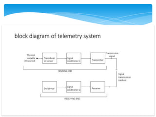
Telemetry System
Telemetry System
❖Introduction
❖Block diagram of Telemetry System
❖Factor influencing Telemetry System Design
❖Classification of Telemetry System
▪ Landline Telemetry System
▪ RF Telemetry System
❖Merits of land line telemetry
❖Demerits of landline telemetry
CONTENTS
* Telemetry is a process of measurement at a long distance.
* Telemetry are used to monitor the physical quantity such as-
temperature, speed, flow rate, liquid level, water level.
* In Greek words the meaning of telemetry is---
* TELE=REMOTE, METER=MEASUREMENT
* Telemetry involves three steps-
1) Converting measured quantity to signal.
2) Transmission of that signal over proper channel.
3) Its reconversion to actual data for recording, displaying(CRT), for
graphical analysis and further computation.
⮚ E.g.- Doctor analysing data of patient from remote location.
INTRODUCTION
▪ Primary criteria for choice and design is accuracy.
▪ System is decided whether transmitted data is in
Analog or Digital domain.
▪ For digital data to be transmitted, error detection,
recognition and correction capability make system
accurate.
▪ Selection of apt. bandwidth for data channel and data
link to avoid crosstalk.
▪ Power level must be low to reduce noise generation.
FACTORS INFLUENCING
TELEMETRY SYSTEM DESIGN
1. Landline Telemetry System—
▪ The telemetry system in which the signal is transmitted through communication cable
like copper, aluminium pair, fiber, cable etc.
▪ The physical link between the transmitter and receiver in landline telemetry system is
in the form of wire that has its characteristics to transmit the signal from transmitter
to receiver .
▪ Power Lines, Telephone lines and Electrical Wires. Distance ranges from 50m to 1km
e.g. : Labs, Industry .
▪ TYPES – Current and Voltage.
2. RADIO FREQUENCY OR WIRE LESS TELEMETRY-
* Radio links from 1km to 50km at 4MHz. For distance >50km microwave links are
used 890MHz to 30GHz. Repeaters are installed after every 30 to 60 km for
long distance transmission.
CLASSIFICATION OF
TELEMETRY SYSTEM
TYPES OF LANDLINE
TELEMETRY SYSTEM-
1- Voltage Telemetry System
2- Current Telemetry System
• Measured variable is transmitted in form of voltage.
• At transmitting end, slide wire is connected in series with battery.
• Slide wire is further connected to Bourdon tube for pressure
measurement.
• When pressure changes, slider actuates the slider of potentiometer.
Thus, change in voltage is transmitted to receiver.
VOLTAGE TELEMETRY SYSTEM
* MERITS -
* Effective for short distance measurement.
* V and I can be easily transmitted.
* Circuitry required is simple.
* Wide variety of primary sensing elements are available to measure required
variable.
* DEMERITS -
* Is difficult to calibrate.
* Need to be protected from EMI ,noises and distortions in the channel.
* Multiplexing is difficult.
* Limited frequency response.
MERITS and DEMERITS OF
LANDLINE TELEMETRY
* No physical link between telemetry transmitter and
receiver .
* Link is established through radio links.
* Examples : in spacecraft, rockets and missiles.
corrective actions can be taken from stations with
help of R.F. links.
* In Instrumentation the output of transducer is
considered as modulating signal.
RF TELEMETRY SYSTEM
* The output of transducer and single conditioner modulates the frequency of a voltage
controlled subcarrier oscillator. Many oscillators, each operating in a dedicated part of the
frequency spectrum, are mixed for radio transmission. As each voltage controlled oscillator
is assigned with a separate frequency of separate frequency spectrum, so each signal can
be transmitted without interfering with other signals.
* At the receiving station, discriminator is tuned to the frequency of each subcarrier. Thus
when measurement value change at source, the output voltage of discriminator change
accordingly.
* THE DISADVANTAGE OF FM TELEMETRY SYSTEM IS CAPACITY OF CHANNELS OFFERED IS
LESS
Explanation OF BLOCK DIAGRAM
THANK YOU

Telemetry system

  • 1.
  • 2.
  • 3.
    ❖Introduction ❖Block diagram ofTelemetry System ❖Factor influencing Telemetry System Design ❖Classification of Telemetry System ▪ Landline Telemetry System ▪ RF Telemetry System ❖Merits of land line telemetry ❖Demerits of landline telemetry CONTENTS
  • 4.
    * Telemetry isa process of measurement at a long distance. * Telemetry are used to monitor the physical quantity such as- temperature, speed, flow rate, liquid level, water level. * In Greek words the meaning of telemetry is--- * TELE=REMOTE, METER=MEASUREMENT * Telemetry involves three steps- 1) Converting measured quantity to signal. 2) Transmission of that signal over proper channel. 3) Its reconversion to actual data for recording, displaying(CRT), for graphical analysis and further computation. ⮚ E.g.- Doctor analysing data of patient from remote location. INTRODUCTION
  • 6.
    ▪ Primary criteriafor choice and design is accuracy. ▪ System is decided whether transmitted data is in Analog or Digital domain. ▪ For digital data to be transmitted, error detection, recognition and correction capability make system accurate. ▪ Selection of apt. bandwidth for data channel and data link to avoid crosstalk. ▪ Power level must be low to reduce noise generation. FACTORS INFLUENCING TELEMETRY SYSTEM DESIGN
  • 7.
    1. Landline TelemetrySystem— ▪ The telemetry system in which the signal is transmitted through communication cable like copper, aluminium pair, fiber, cable etc. ▪ The physical link between the transmitter and receiver in landline telemetry system is in the form of wire that has its characteristics to transmit the signal from transmitter to receiver . ▪ Power Lines, Telephone lines and Electrical Wires. Distance ranges from 50m to 1km e.g. : Labs, Industry . ▪ TYPES – Current and Voltage. 2. RADIO FREQUENCY OR WIRE LESS TELEMETRY- * Radio links from 1km to 50km at 4MHz. For distance >50km microwave links are used 890MHz to 30GHz. Repeaters are installed after every 30 to 60 km for long distance transmission. CLASSIFICATION OF TELEMETRY SYSTEM
  • 8.
    TYPES OF LANDLINE TELEMETRYSYSTEM- 1- Voltage Telemetry System 2- Current Telemetry System
  • 9.
    • Measured variableis transmitted in form of voltage. • At transmitting end, slide wire is connected in series with battery. • Slide wire is further connected to Bourdon tube for pressure measurement. • When pressure changes, slider actuates the slider of potentiometer. Thus, change in voltage is transmitted to receiver. VOLTAGE TELEMETRY SYSTEM
  • 11.
    * MERITS - *Effective for short distance measurement. * V and I can be easily transmitted. * Circuitry required is simple. * Wide variety of primary sensing elements are available to measure required variable. * DEMERITS - * Is difficult to calibrate. * Need to be protected from EMI ,noises and distortions in the channel. * Multiplexing is difficult. * Limited frequency response. MERITS and DEMERITS OF LANDLINE TELEMETRY
  • 12.
    * No physicallink between telemetry transmitter and receiver . * Link is established through radio links. * Examples : in spacecraft, rockets and missiles. corrective actions can be taken from stations with help of R.F. links. * In Instrumentation the output of transducer is considered as modulating signal. RF TELEMETRY SYSTEM
  • 14.
    * The outputof transducer and single conditioner modulates the frequency of a voltage controlled subcarrier oscillator. Many oscillators, each operating in a dedicated part of the frequency spectrum, are mixed for radio transmission. As each voltage controlled oscillator is assigned with a separate frequency of separate frequency spectrum, so each signal can be transmitted without interfering with other signals. * At the receiving station, discriminator is tuned to the frequency of each subcarrier. Thus when measurement value change at source, the output voltage of discriminator change accordingly. * THE DISADVANTAGE OF FM TELEMETRY SYSTEM IS CAPACITY OF CHANNELS OFFERED IS LESS Explanation OF BLOCK DIAGRAM
  • 15.