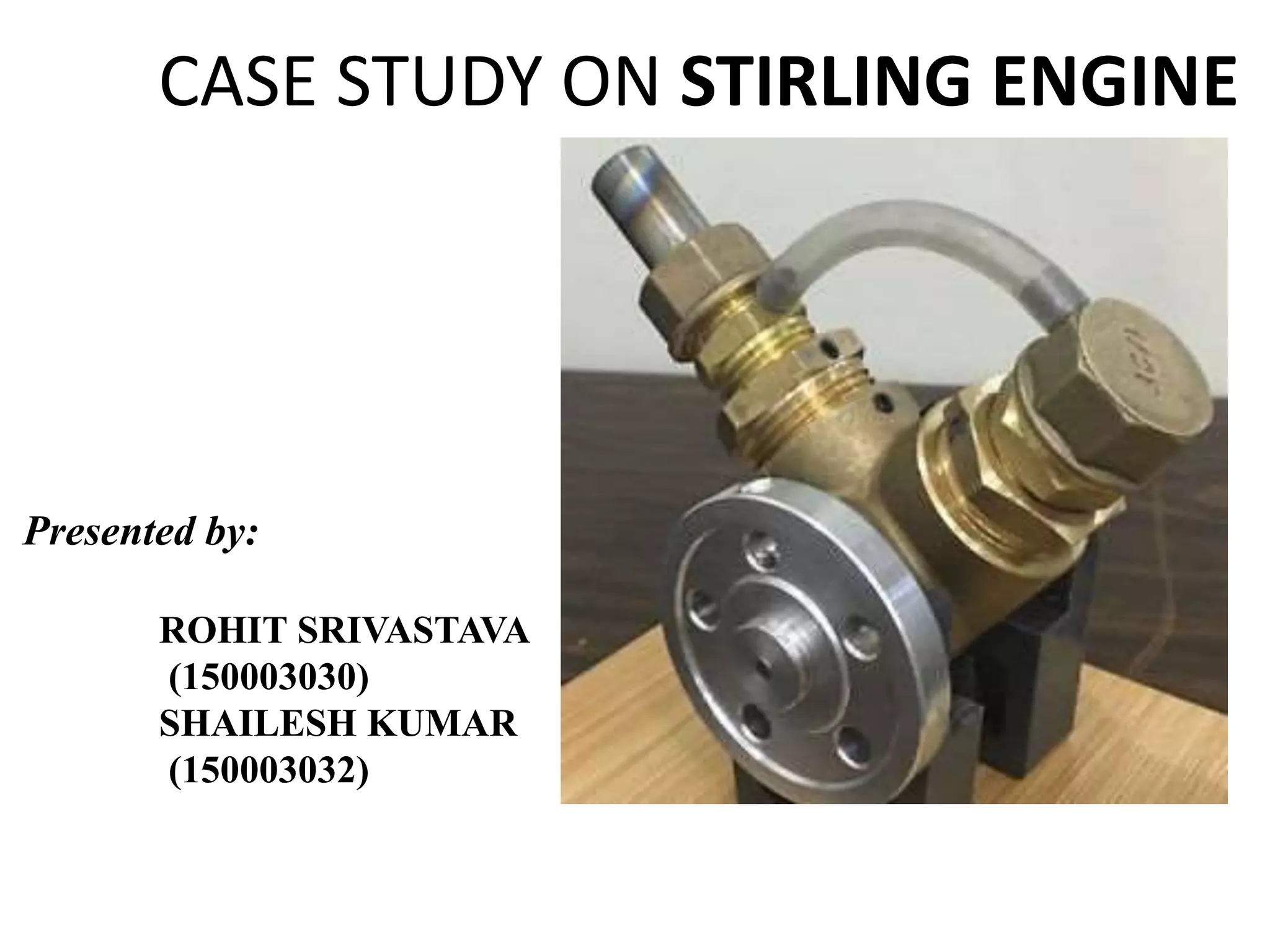
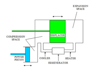
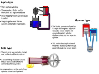
This document provides an overview of Stirling engines, including:
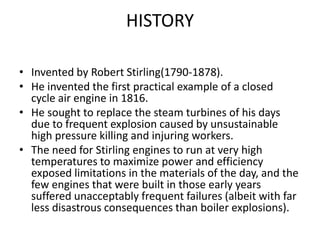
- A brief history of their invention in the 18th century by Robert Stirling.
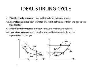
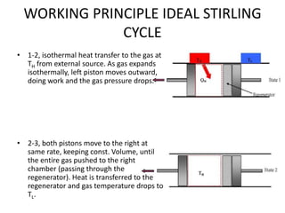
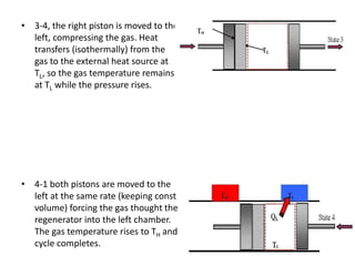
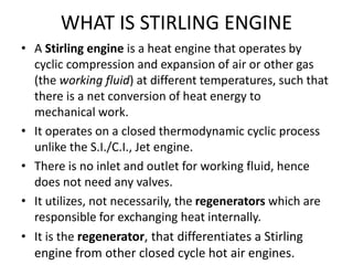
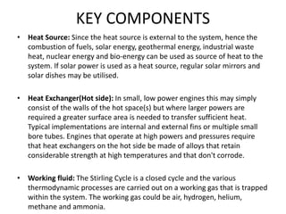
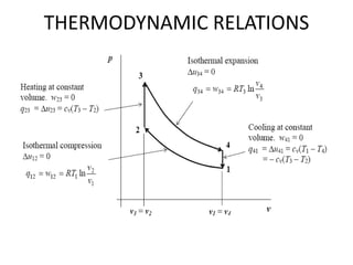
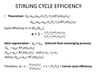
- An explanation of the Stirling cycle and ideal working principles.
- Descriptions of the key components of Stirling engines like the heat source, displacer, regenerator and their functions.
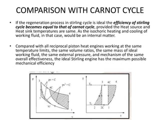
- Comparisons of Stirling engines to Carnot engines and internal combustion engines in terms of efficiency and practical issues.
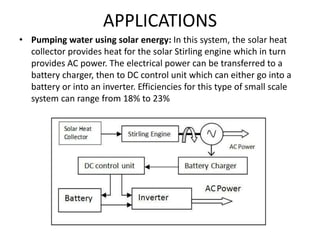
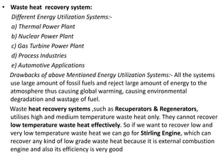
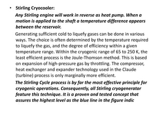
- Examples of applications like waste heat recovery, solar power pumping, and Stirling cryocoolers.