Downloaded 29 times
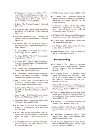
![Stirling engine
For the adiabatic Stirling cycle, see Stirling cycle.
A Stirling engine is a heat engine that operates by
Alpha type Stirling engine. There are two cylinders. The expan-
sion cylinder (red) is maintained at a high temperature while the
compression cylinder (blue) is cooled. The passage between the
two cylinders contains the regenerator.
cyclic compression and expansion of air or other gas
(the working fluid) at different temperatures, such that
there is a net conversion of heat energy to mechani-
cal work.[1][2]
More specifically, the Stirling engine is
a closed-cycle regenerative heat engine with a perma-
nently gaseous working fluid. Closed-cycle, in this con-
text, means a thermodynamic system in which the work-
ing fluid is permanently contained within the system, and
regenerative describes the use of a specific type of in-
ternal heat exchanger and thermal store, known as the
regenerator. The inclusion of a regenerator differentiates
the Stirling engine from other closed cycle hot air engines.
Originally conceived in 1816 as an industrial prime mover
to rival the steam engine, its practical use was largely
confined to low-power domestic applications for over a
century.[3]
The Stirling engine is noted for high efficiency compared
to steam engines,[4]
quiet operation, and its ability to use
almost any heat source. The heat energy source is gen-
erated external to the Stirling engine rather than by in-
ternal combustion as with the Otto cycle or Diesel cycle
engines. Because the Stirling engine is compatible with
alternative and renewable energy sources it could become
increasingly significant as the price of conventional fuels
rises, and also in light of concerns such as peak oil and
Beta type Stirling engine. There is only one cylinder, hot at one
end and cold at the other. A loose-fitting displacer shunts the air
between the hot and cold ends of the cylinder. A power piston at
the end of the cylinder drives the flywheel.
climate change. This engine is currently exciting inter-
est as the core component of micro combined heat and
power (CHP) units, in which it is more efficient and safer
than a comparable steam engine.[5][6]
However, it has a
low power-to-weight ratio [4]
rendering it more suitable
for use in static installations where space and weight are
not at a premium.
1](https://image.slidesharecdn.com/stirlingengine-170228165434/85/Stirling-engine-1-320.jpg)
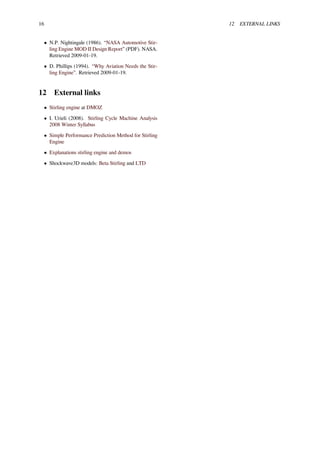
![2 2 HISTORY
1 Name and classification
Stirling engine running.
Robert Stirling was a Scottish minister who invented the
first practical example of a closed cycle air engine in
1816, and it was suggested by Fleeming Jenkin as early
as 1884 that all such engines should therefore generi-
cally be called Stirling engines. This naming proposal
found little favour, and the various types on the market
continued to be known by the name of their individual
designers or manufacturers, e.g., Rider’s, Robinson’s, or
Heinrici’s (hot) air engine. In the 1940s, the Philips com-
pany was seeking a suitable name for its own version of
the 'air engine', which by that time had been tested with
working fluids other than air, and decided upon 'Stir-
ling engine' in April 1945.[7]
However, nearly thirty years
later, Graham Walker still had cause to bemoan the fact
such terms as 'hot air engine' remained interchangeable
with 'Stirling engine', which itself was applied widely and
indiscriminately;[8]
a situation that continues.[9]
Like the steam engine, the Stirling engine is tradition-
ally classified as an external combustion engine, as all
heat transfers to and from the working fluid take place
through a solid boundary (heat exchanger) thus isolating
the combustion process and any contaminants it may pro-
duce from the working parts of the engine. This contrasts
with an internal combustion engine where heat input is by
combustion of a fuel within the body of the working fluid.
Most of the many possible implementations of the Stir-
ling engine fall into the category of reciprocating piston
engine.
2 History
2.1 Invention and early development
The Stirling engine (or Stirling’s air engine as it was
known at the time) was invented and patented by Robert
Stirling in 1816.[10]
It followed earlier attempts at mak-
ing an air engine but was probably the first put to prac-
tical use when, in 1818, an engine built by Stirling was
employed pumping water in a quarry.[11]
The main sub-
Illustration from Robert Stirling’s 1816 patent application of the
air engine design which later came to be known as the Stirling
Engine
ject of Stirling’s original patent was a heat exchanger,
which he called an "economiser" for its enhancement of
fuel economy in a variety of applications. The patent
also described in detail the employment of one form
of the economiser in his unique closed-cycle air engine
design[12]
in which application it is now generally known
as a "regenerator". Subsequent development by Robert
Stirling and his brother James, an engineer, resulted in
patents for various improved configurations of the origi-
nal engine including pressurization, which by 1843, had
sufficiently increased power output to drive all the ma-
chinery at a Dundee iron foundry.[13]
Though it has been disputed,[14]
it is widely supposed that
as well as saving fuel, the inventors were motivated to cre-
ate a safer alternative to the steam engines of the time,[15]
whose boilers frequently exploded, causing many injuries
and fatalities.[16][17]
The need for Stirling engines to run at very high temper-
atures to maximize power and efficiency exposed limi-
tations in the materials of the day, and the few engines
that were built in those early years suffered unaccept-
ably frequent failures (albeit with far less disastrous con-
sequences than a boiler explosion[18]
) — for example, the
Dundee foundry engine was replaced by a steam engine
after three hot cylinder failures in four years.[19]
2.2 Later nineteenth century
Subsequent to the failure of the Dundee foundry engine
there is no record of the Stirling brothers having any fur-
ther involvement with air engine development and the
Stirling engine never again competed with steam as an
industrial scale power source (steam boilers were becom-
ing safer[20]
and steam engines more efficient, thus pre-
senting less of a target to rival prime movers). However,
from about 1860, smaller engines of the Stirling/hot air
type were produced in substantial numbers finding ap-
plications wherever a reliable source of low to medium](https://image.slidesharecdn.com/stirlingengine-170228165434/85/Stirling-engine-2-320.jpg)
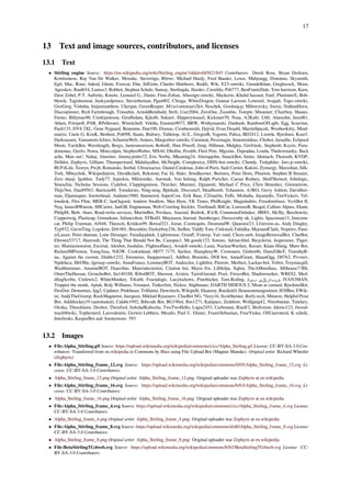
![2.3 Twentieth century revival 3
A typical late nineteenth/early twentieth century water pumping
engine by the Rider-Ericsson Engine Company
power was required, such as raising water or providing air
for church organs.[21]
These generally operated at lower
temperatures so as not to tax available materials, so were
relatively inefficient. Their selling point was that, unlike
a steam engine, they could be operated safely by anybody
capable of managing a fire.[22]
Several types remained in
production beyond the end of the century, but apart from
a few minor mechanical improvements the design of the
Stirling engine in general stagnated during this period.[23]
2.3 Twentieth century revival
During the early part of the twentieth century the role of
the Stirling engine as a “domestic motor”[24]
was gradu-
ally taken over by electric motors and small internal com-
bustion engines. By the late 1930s, it was largely forgot-
ten, only produced for toys and a few small ventilating
fans.[25]
Around that time, Philips was seeking to expand sales of
its radios into parts of the world where electricity and
batteries were not consistently available. Philips’ man-
agement decided that offering a low-power portable gen-
erator would facilitate such sales and asked a group of
engineers at the company’s research lab in Eindhoven to
evaluate alternative ways of achieving this aim. After a
systematic comparison of various prime movers, the team
decided to go forward with the Stirling engine, citing its
quiet operation (both audibly and in terms of radio inter-
ference) and ability to run on a variety of heat sources
(common lamp oil – “cheap and available everywhere” –
was favored).[26]
They were also aware that, unlike steam
and internal combustion engines, virtually no serious de-
velopment work had been carried out on the Stirling en-
gine for many years and asserted that modern materials
and know-how should enable great improvements.[27]
Philips MP1002CA Stirling generator of 1951
By 1951, the 180/200 W generator set designated
MP1002CA (known as the “Bungalow set”) was ready
for production and an initial batch of 250 was planned,
but soon it became clear that they could not be made
at a competitive price. Additionally, the advent of tran-
sistor radios and their much lower power requirements
meant that the original rationale for the set was disap-
pearing. Approximately 150 of these sets were eventu-
ally produced.[28]
Some found their way into university
and college engineering departments around the world[29]
giving generations of students a valuable introduction to
the Stirling engine.
In parallel with the Bungalow set, Philips developed ex-
perimental Stirling engines for a wide variety of appli-
cations and continued to work in the field until the late
1970s, but only achieved commercial success with the
“reversed Stirling engine” cryocooler. However, they
filed a large number of patents and amassed a wealth of
information, which they licensed to other companies and
which formed the basis of much of the development work
in the modern era.[30]
In 1996, the Swedish navy commissioned three Gotland-
class submarines. On the surface, these boats are pro-
pelled by marine diesel engines. However when sub-
merged, they use a Stirling-driven generator to recharge
batteries or provide electrical power for propulsion. A
supply of liquid oxygen is carried to support burning of
diesel fuel to power the engine. Stirling engines are also
fitted to the Swedish Södermanland-class submarines.
Swedish shipbuilder Kockums has also supplied Stirling
engines to Japan, which intendes to fit them to all its
new submarines. In a submarine application, the Stirling
engine offers the advantage of being exceptionally quiet
when running.
Stirling engines are at the heart of Concentrated Solar](https://image.slidesharecdn.com/stirlingengine-170228165434/85/Stirling-engine-3-320.jpg)
![4 3 FUNCTIONAL DESCRIPTION
Power technology, known as CSP Dish-Stirling. Several
companies such as Cleanergy, Ripasso Energy and United
Sun Systems International are involved in this technology.
3 Functional description
The engine is designed so that the working gas is gener-
ally compressed in the colder portion of the engine and
expanded in the hotter portion resulting in a net conver-
sion of heat into work.[2]
An internal regenerative heat ex-
changer increases the Stirling engine’s thermal efficiency
compared to simpler hot air engines lacking this feature.
3.1 Key components
As a consequence of closed cycle operation, the heat driv-
ing a Stirling engine must be transmitted from a heat
source to the working fluid by heat exchangers and finally
to a heat sink. A Stirling engine system has at least one
heat source, one heat sink and up to five heat exchangers.
Some types may combine or dispense with some of these.
3.1.1 Heat source
Point focus parabolic mirror with Stirling engine at its center and
its solar tracker at Plataforma Solar de Almería (PSA) in Spain
The heat source may be provided by the combustion of
a fuel and, since the combustion products do not mix
with the working fluid and hence do not come into con-
tact with the internal parts of the engine, a Stirling engine
can run on fuels that would damage other engines type’s
internals, such as landfill gas, which may contain siloxane
which can deposit abrasive silicon dioxide in conventional
engines.[31]
Other suitable heat sources include concentrated solar en-
ergy, geothermal energy, nuclear energy, waste heat and
bioenergy. If solar power is used as a heat source, regular
solar mirrors and solar dishes may be utilised. The use of
Fresnel lenses and mirrors has also been advocated, for
example in planetary surface exploration.[32]
Solar pow-
ered Stirling engines are increasingly popular as they of-
Dish Stirling from SES
fer an environmentally sound option for producing power
while some designs are economically attractive in devel-
opment projects.[33]
3.1.2 Heater / hot side heat exchanger
In small, low power engines this may simply consist of
the walls of the hot space(s) but where larger powers are
required a greater surface area is needed to transfer suffi-
cient heat. Typical implementations are internal and ex-
ternal fins or multiple small bore tubes.
Designing Stirling engine heat exchangers is a balance be-
tween high heat transfer with low viscous pumping losses
and low dead space (unswept internal volume). Engines
that operate at high powers and pressures require that heat
exchangers on the hot side be made of alloys that retain
considerable strength at temperature and that don't cor-
rode or creep.
3.1.3 Regenerator
Main article: Regenerative heat exchanger
In a Stirling engine, the regenerator is an internal heat ex-
changer and temporary heat store placed between the hot
and cold spaces such that the working fluid passes through
it first in one direction then the other, taking heat from the
fluid in one direction, and returning it in the other. It can
be as simple as metal mesh or foam, and benefits from
high surface area, high heat capacity, low conductivity
and low flow friction.[34]
Its function is to retain within
the system that heat that would otherwise be exchanged
with the environment at temperatures intermediate to the
maximum and minimum cycle temperatures,[35]
thus en-
abling the thermal efficiency of the cycle to approach the
limiting Carnot efficiency.
The primary effect of regeneration in a Stirling engine](https://image.slidesharecdn.com/stirlingengine-170228165434/85/Stirling-engine-4-320.jpg)
![3.2 Configurations 5
is to increase the thermal efficiency by 'recycling' in-
ternal heat that would otherwise pass through the en-
gine irreversibly. As a secondary effect, increased ther-
mal efficiency yields a higher power output from a given
set of hot and cold end heat exchangers. These usually
limit the engine’s heat throughput. In practice this addi-
tional power may not be fully realized as the additional
“dead space” (unswept volume) and pumping loss inher-
ent in practical regenerators reduces the potential effi-
ciency gains from regeneration.
The design challenge for a Stirling engine regenerator is
to provide sufficient heat transfer capacity without intro-
ducing too much additional internal volume ('dead space')
or flow resistance. These inherent design conflicts are one
of many factors that limit the efficiency of practical Stir-
ling engines. A typical design is a stack of fine metal wire
meshes, with low porosity to reduce dead space, and with
the wire axes perpendicular to the gas flow to reduce con-
duction in that direction and to maximize convective heat
transfer.[36]
The regenerator is the key component invented by Robert
Stirling and its presence distinguishes a true Stirling en-
gine from any other closed cycle hot air engine. Many
small 'toy' Stirling engines, particularly low-temperature
difference (LTD) types, do not have a distinct regenera-
tor component and might be considered hot air engines,
however a small amount of regeneration is provided by
the surface of the displacer itself and the nearby cylinder
wall, or similarly the passage connecting the hot and cold
cylinders of an alpha configuration engine.
3.1.4 Cooler / cold side heat exchanger
In small, low power engines this may simply consist of
the walls of the cold space(s), but where larger powers
are required a cooler using a liquid like water is needed
to transfer sufficient heat.
3.1.5 Heat sink
The heat sink is typically the environment at ambient
temperature. In the case of medium to high power en-
gines, a radiator is required to transfer the heat from the
engine to the ambient air. Marine engines can use the
ambient water. In the case of combined heat and power
systems, the engine’s cooling water is used directly or in-
directly for heating purposes.
Alternatively, heat may be supplied at ambient temper-
ature and the heat sink maintained at a lower tempera-
ture by such means as cryogenic fluid (see Liquid nitrogen
economy) or iced water.
3.1.6 Displacer
The displacer is a special-purpose piston, used in Beta
and Gamma type Stirling engines, to move the working
gas back and forth between the hot and cold heat exchang-
ers. Depending on the type of engine design, the displacer
may or may not be sealed to the cylinder, i.e. it may be
a loose fit within the cylinder, allowing the working gas
to pass around it as it moves to occupy the part of the
cylinder beyond.
3.2 Configurations
There are three major types of Stirling engines, that are
distinguished by the way they move the air between the
hot and cold areas:
1. The alpha configuration has two power pistons, one
in a hot cylinder, one in a cold cylinder, and the gas is
driven between the two by the pistons; it is typically
in a V-formation with the pistons joined at the same
point on a crankshaft.
2. The beta configuration has a single cylinder with a
hot end and a cold end, containing a power piston
and a 'displacer' that drives the gas between the hot
and cold ends. It is typically used with a rhombic
drive to achieve the phase difference between the
displacer and power pistons, but they can be joined
90 degrees out of phase on a crankshaft.
3. The gamma configuration has two cylinders: one
containing a displacer, with a hot and a cold end, and
one for the power piston; they are joined to form a
single space with the same pressure in both cylin-
ders; the pistons are typically in parallel and joined
90 degrees out of phase on a crankshaft.
3.2.1 Alpha configuration operation
An alpha Stirling contains two power pistons in sepa-
rate cylinders, one hot and one cold. The hot cylinder is
situated inside the high temperature heat exchanger and
the cold cylinder is situated inside the low temperature
heat exchanger. This type of engine has a high power-to-
volume ratio but has technical problems due to the usually
high temperature of the hot piston and the durability of
its seals.[37]
In practice, this piston usually carries a large
insulating head to move the seals away from the hot zone
at the expense of some additional dead space. The crank
angle has a major effect on efficiency and the best angle
frequently has to be found experimentally. An angle of
90° frequently locks.
The following diagrams do not show internal heat ex-
changers in the compression and expansion spaces, which
are needed to produce power. A regenerator would be
placed in the pipe connecting the two cylinders.](https://image.slidesharecdn.com/stirlingengine-170228165434/85/Stirling-engine-5-320.jpg)
![6 3 FUNCTIONAL DESCRIPTION
3.2.2 Beta configuration operation
A beta Stirling has a single power piston arranged within
the same cylinder on the same shaft as a displacer piston.
The displacer piston is a loose fit and does not extract any
power from the expanding gas but only serves to shuttle
the working gas between the hot and cold heat exchang-
ers. When the working gas is pushed to the hot end of the
cylinder it expands and pushes the power piston. When
it is pushed to the cold end of the cylinder it contracts
and the momentum of the machine, usually enhanced by
a flywheel, pushes the power piston the other way to com-
press the gas. Unlike the alpha type, the beta type avoids
the technical problems of hot moving seals.[38]
Again, the following diagrams do not show any internal
heat exchangers or a regenerator, which would be placed
in the gas path around the displacer. If a regenerator is
used in a beta engine, it is usually in the position of the
displacer and moving, often as a volume of wire mesh.
3.2.3 Gamma configuration operation
A gamma Stirling is simply a beta Stirling in which the
power piston is mounted in a separate cylinder alongside
the displacer piston cylinder, but is still connected to the
same flywheel. The gas in the two cylinders can flow
freely between them and remains a single body. This con-
figuration produces a lower compression ratio because of
the volume of the connection between the two but is me-
chanically simpler and often used in multi-cylinder Stir-
ling engines.
3.2.4 Other types
Other Stirling configurations continue to interest engi-
neers and inventors.
The rotary Stirling engine seeks to convert power from
the Stirling cycle directly into torque, similar to the rotary
combustion engine. No practical engine has yet been built
but a number of concepts, models and patents have been
produced for example the Quasiturbine engine.[39]
The hybrid between piston and rotary configuration is a
double acting engine. This design rotates the displacers
on either side of the power piston
Another alternative is the Fluidyne engine (Fluidyne
heat pump), which uses hydraulic pistons to implement
the Stirling cycle. The work produced by a Fluidyne en-
gine goes into pumping the liquid. In its simplest form,
the engine contains a working gas, a liquid and two non-
return valves.
Top view of two rotating displacer powering the horizontal piston.
Regenerators and radiator removed for clarity
The Ringbom engine concept published in 1907 has no
rotary mechanism or linkage for the displacer. This is
instead driven by a small auxiliary piston, usually a thick
displacer rod, with the movement limited by stops.[40][41]
The two-cylinder Stirling with Ross yoke is a two-
cylinder stirling engine (not positioned at 90°, but at
0°) connected with a special yoke. The engine config-
uration/yoke setup was invented by Andy Ross (engi-
neer).[42]
The Franchot engine is a double acting engine invented
by ‘Franchot’ in the nineteenth century. A double acting
engine is one where both sides of the piston are acted
upon by the pressure of the working fluid. One of the
simplest forms of a double acting machine, the Franchot
engine consists of two pistons and two cylinders and acts
like two separate alpha machines. In the Franchot engine,
each piston acts in two gas phases, which makes more
efficient use of the mechanical components than a single
acting alpha machine. However, a disadvantage of this
machine is that one connecting rod must have a sliding
seal at the hot side of the engine, which is a difficult task
when dealing with high pressures and high temperatures.
3.2.5 Free piston Stirling engines
“Free piston” Stirling engines include those with liquid
pistons and those with diaphragms as pistons. In a “free
piston” device, energy may be added or removed by an
electrical linear alternator, pump or other coaxial device.
This avoids the need for a linkage, and reduces the num-
ber of moving parts. In some designs, friction and wear
are nearly eliminated by the use of non-contact gas bear-
ings or very precise suspension through planar springs.
Four basic steps in the cycle of a “free piston” Stirling
engine are:
1. The power piston is pushed outwards by the expand-
ing gas thus doing work. Gravity plays no role in the
cycle.
2. The gas volume in the engine increases and therefore](https://image.slidesharecdn.com/stirlingengine-170228165434/85/Stirling-engine-6-320.jpg)
![3.2 Configurations 7
Various free-piston Stirling configurations... F."free cylinder”, G.
Fluidyne, H. “double-acting” Stirling (typically 4 cylinders)
the pressure reduces, which causes a pressure differ-
ence across the displacer rod to force the displacer
towards the hot end. When the displacer moves
the piston is almost stationary and therefore the gas
volume is almost constant. This step results in the
constant volume cooling process, which reduces the
pressure of the gas.
3. The reduced pressure now arrests the outward mo-
tion of the piston and it begins to accelerate towards
the hot end again and by its own inertia, compresses
the now cold gas, which is mainly in the cold space.
4. As the pressure increases, a point is reached where
the pressure differential across the displacer rod be-
comes large enough to begin to push the displacer
rod (and therefore also the displacer) towards the
piston and thereby collapsing the cold space and
transferring the cold, compressed gas towards the
hot side in an almost constant volume process. As
the gas arrives in the hot side the pressure increases
and begins to move the piston outwards to initiate
the expansion step as explained in (1).
In the early 1960s, W.T. Beale invented a free piston ver-
sion of the Stirling engine to overcome the difficulty of
lubricating the crank mechanism.[43]
While the invention
of the basic free piston Stirling engine is generally at-
tributed to Beale, independent inventions of similar types
of engines were made by E.H. Cooke-Yarborough and C.
West at the Harwell Laboratories of the UKAERE.[44]
G.M. Benson also made important early contributions
and patented many novel free-piston configurations.[45]
The first known mention of a Stirling cycle machine us-
ing freely moving components is a British patent disclo-
sure in 1876.[46]
This machine was envisaged as a refrig-
erator (i.e., the reversed Stirling cycle). The first con-
sumer product to utilize a free piston Stirling device was
a portable refrigerator manufactured by Twinbird Cor-
poration of Japan and offered in the US by Coleman in
2004.
Cutaway of the flat Stirling engine: 10.Hot cylinder 11.A vol-
ume of hot cylinder 12.B volume of hot cylinder 17.Warm pis-
ton diaphragm 18.Heating medium 19.Piston rod 20.Cold cylin-
der 21.A Volume of cold cylinder 22.B Volume of cold cylin-
der 27.Cold piston diaphragm 28.Coolant medium 30.Working
cylinder 31.A volume of working cylinder 32.B volume of work-
ing cylinder 37.Working piston diaphragm 41.Regenerator mass
of A volume 42.Regenerator mass of B volume 48.Heat accu-
mulator 50.Thermal insulation 60.Generator 63.Magnetic circuit
64.Electrical winding 70.Channel connecting warm and working
cylinders
Flat Stirling engine Design of the flat double-acting
Stirling engine solves the drive of a displacer with the help
of the fact that areas of the hot and cold pistons of the dis-
placer are different. The drive does so without any me-
chanical transmission . Using diaphragms eliminates fric-
tion and need for lubricants. When the displacer is in mo-
tion, the generator holds the working piston in the limit
position, which brings the engine working cycle close to
an ideal Stirling cycle. The ratio of the area of the heat
exchangers to the volume of the machine increases by the
implementation of a flat design. Flat design of the work-
ing cylinder approximates thermal process of the expan-
sion and compression closer to the isothermal one. The
disadvantage is a large area of the thermal insulation be-
tween the hot and cold space. [47]
Thermoacoustic cycle Thermoacoustic devices are
very different from Stirling devices, although the indi-
vidual path travelled by each working gas molecule does
follow a real Stirling cycle. These devices include the
thermoacoustic engine and thermoacoustic refrigerator.
High-amplitude acoustic standing waves cause compres-
sion and expansion analogous to a Stirling power piston,
while out-of-phase acoustic travelling waves cause dis-
placement along a temperature gradient, analogous to a
Stirling displacer piston. Thus a thermoacoustic device
typically does not have a displacer, as found in a beta or
gamma Stirling.](https://image.slidesharecdn.com/stirlingengine-170228165434/85/Stirling-engine-7-320.jpg)
![8 4 THEORY
3.3 Other developments
Starting in 1986, Infinia Corporation began develop-
ing both highly reliable pulsed free-piston Stirling en-
gines, and thermoacoustic coolers using related technol-
ogy. The published design uses flexural bearings and her-
metically sealed Helium gas cycles, to achieve tested re-
liabilities exceeding 20 years. As of 2010, the corpora-
tion had amassed more than 30 patents, and developed a
number of commercial products for both combined heat
and power, and solar power.[48]
More recently, NASA has
considered nuclear-decay heated Stirling Engines for ex-
tended missions to the outer solar system.[49]
At the recent
Cable-Tec Expo put on by the Society of Cable Telecom-
munications Engineers, Dean Kamen took the stage with
Time Warner Cable Chief Technology Officer Mike La-
Joie to announce a new initiative between his company
Deka Research and the SCTE. Kamen refers to it as a
Stirling engine.[50][51]
4 Theory
Main article: Stirling cycle
The idealised Stirling cycle consists of four
A pressure/volume graph of the idealized Stirling cycle
thermodynamic processes acting on the working
fluid:
1. Isothermal expansion. The expansion-space and as-
sociated heat exchanger are maintained at a con-
stant high temperature, and the gas undergoes near-
isothermal expansion absorbing heat from the hot
source.
2. Constant-volume (known as isovolumetric or
isochoric) heat-removal. The gas is passed through
the regenerator, where it cools, transferring heat to
the regenerator for use in the next cycle.
3. Isothermal compression. The compression space
and associated heat exchanger are maintained at a
constant low temperature so the gas undergoes near-
isothermal compression rejecting heat to the cold
sink
4. Constant-volume (known as isovolumetric or
isochoric) heat-addition. The gas passes back
through the regenerator where it recovers much of
the heat transferred in 2, heating up on its way to
the expansion space.
Theoretical thermal efficiency equals that of the hypo-
thetical Carnot cycle - i.e. the highest efficiency attain-
able by any heat engine. However, though it is useful
for illustrating general principles, the ideal cycle deviates
substantially from practical Stirling engines. It has been
argued that its indiscriminate use in many standard books
on engineering thermodynamics has done a disservice to
the study of Stirling engines in general.[52][53]
Other real-world issues reduce the efficiency of actual
engines, due to limits of convective heat transfer, and
viscous flow (friction). There are also practical mechan-
ical considerations, for instance a simple kinematic link-
age may be favoured over a more complex mechanism
needed to replicate the idealized cycle, and limitations
imposed by available materials such as non-ideal prop-
erties of the working gas, thermal conductivity, tensile
strength, creep, rupture strength, and melting point. A
question that often arises is whether the ideal cycle with
isothermal expansion and compression is in fact the cor-
rect ideal cycle to apply to the Stirling engine. Profes-
sor C. J. Rallis has pointed out that it is very difficult to
imagine any condition where the expansion and compres-
sion spaces may approach isothermal behavior and it is
far more realistic to imagine these spaces as adiabatic.[54]
An ideal analysis where the expansion and compression
spaces are taken to be adiabatic with isothermal heat ex-
changers and perfect regeneration was analyzed by Rallis
and presented as a better ideal yardstick for Stirling ma-
chinery. He called this cycle the 'pseudo-Stirling cycle'
or 'ideal adiabatic Stirling cycle'. An important conse-
quence of this ideal cycle is that it does not predict Carnot
efficiency. A further conclusion of this ideal cycle is that
maximum efficiencies are found at lower compression ra-
tios, a characteristic observed in real machines. In an in-
dependent work, T. Finkelstein also assumed adiabatic
expansion and compression spaces in his analysis of Stir-
ling machinery [55]
4.1 Operation
Since the Stirling engine is a closed cycle, it contains a
fixed mass of gas called the “working fluid”, most com-
monly air, hydrogen or helium. In normal operation, the
engine is sealed and no gas enters or leaves the engine.
No valves are required, unlike other types of piston en-
gines. The Stirling engine, like most heat engines, cycles](https://image.slidesharecdn.com/stirlingengine-170228165434/85/Stirling-engine-8-320.jpg)
![4.2 Pressurization 9
through four main processes: cooling, compression, heat-
ing and expansion. This is accomplished by moving the
gas back and forth between hot and cold heat exchangers,
often with a regenerator between the heater and cooler.
The hot heat exchanger is in thermal contact with an ex-
ternal heat source, such as a fuel burner, and the cold heat
exchanger being in thermal contact with an external heat
sink, such as air fins. A change in gas temperature causes
a corresponding change in gas pressure, while the motion
of the piston causes the gas to be alternately expanded
and compressed.
The gas follows the behaviour described by the gas
laws that describe how a gas’ pressure, temperature and
volume are related. When the gas is heated, because it is
in a sealed chamber, the pressure rises and this then acts
on the power piston to produce a power stroke. When the
gas is cooled the pressure drops and this means that less
work needs to be done by the piston to compress the gas
on the return stroke, thus yielding a net power output.
The ideal Stirling cycle is unattainable in the real world,
as with any heat engine; efficiencies of 50% have been
reached,[4]
similar to the maximum figure for Diesel cy-
cle engines.[56]
The efficiency of Stirling machines is also
linked to the environmental temperature; a higher effi-
ciency is obtained when the weather is cooler, thus mak-
ing this type of engine less interesting in places with
warmer climates. As with other external combustion en-
gines, Stirling engines can use heat sources other than
from combustion of fuels.
When one side of the piston is open to the atmosphere,
the operation is slightly different. As the sealed volume
of working gas comes in contact with the hot side, it ex-
pands, doing work on both the piston and on the atmo-
sphere. When the working gas contacts the cold side, its
pressure drops below atmospheric pressure and the atmo-
sphere pushes on the piston and does work on the gas.
To summarize, the Stirling engine uses the temperature
difference between its hot end and cold end to establish
a cycle of a fixed mass of gas, heated and expanded, and
cooled and compressed, thus converting thermal energy
into mechanical energy. The greater the temperature dif-
ference between the hot and cold sources, the greater the
thermal efficiency. The maximum theoretical efficiency
is equivalent to the Carnot cycle, however the efficiency
of real engines is less than this value due to friction and
other losses.
Very low-power engines have been built that run on a tem-
perature difference of as little as 0.5 K.[57]
In a displacer
type stirling engine you have one piston and one dis-
placer. A temperature difference is required between the
top and bottom of the large cylinder to run the engine. In
the case of the low-temperature difference (LTD) stir-
ling engine, temperature difference between your hand
and the surrounding air can be enough to run the engine.
The power piston in the displacer type stirling engine, is
tightly sealed and is controlled to move up and down as
Video showing the compressor and displacer of a very small Stir-
ling Engine in action
the gas inside expands. The displacer on the other hand is
very loosely fitted so that air can move freely between the
hot and cold sections of the engine as the piston moves up
and down. The displacer moves up and down to control
the heating and cooling of the gas in the engine.
There are two positions:
1. When the displacer is near the top of the large cylin-
der; inside the engine most of the gas has been
heated by the heat source and it expands. This in-
creases the pressure, which forces the piston up.
2. When the displacer is near the bottom of the large
cylinder; most of the gas in the engine has now
cooled and contracts causing the pressure to de-
crease, which in turn allows the piston to move down
and compress the gas.
4.2 Pressurization
In most high power Stirling engines, both the minimum
pressure and mean pressure of the working fluid are above
atmospheric pressure. This initial engine pressurization
can be realized by a pump, or by filling the engine from
a compressed gas tank, or even just by sealing the en-
gine when the mean temperature is lower than the mean
operating temperature. All of these methods increase
the mass of working fluid in the thermodynamic cycle.
All of the heat exchangers must be sized appropriately to
supply the necessary heat transfer rates. If the heat ex-
changers are well designed and can supply the heat flux
needed for convective heat transfer, then the engine, in
a first approximation, produces power in proportion to
the mean pressure, as predicted by the West number, and
Beale number. In practice, the maximum pressure is also
limited to the safe pressure of the pressure vessel. Like
most aspects of Stirling engine design, optimization is
multivariate, and often has conflicting requirements.[58]
A difficulty of pressurization is that while it improves the
power, the heat required increases proportionately to the](https://image.slidesharecdn.com/stirlingengine-170228165434/85/Stirling-engine-9-320.jpg)
![10 5 ANALYSIS
increased power. This heat transfer is made increasingly
difficult with pressurization since increased pressure also
demands increased thicknesses of the walls of the engine,
which, in turn, increase the resistance to heat transfer.
4.3 Lubricants and friction
A modern Stirling engine and generator set with 55 kW electrical
output, for combined heat and power applications
At high temperatures and pressures, the oxygen in air-
pressurized crankcases, or in the working gas of hot air
engines, can combine with the engine’s lubricating oil
and explode. At least one person has died in such an
explosion.[59]
Lubricants can also clog heat exchangers, especially the
regenerator. For these reasons, designers prefer non-
lubricated, low-coefficient of friction materials (such as
rulon or graphite), with low normal forces on the mov-
ing parts, especially for sliding seals. Some designs avoid
sliding surfaces altogether by using diaphragms for sealed
pistons. These are some of the factors that allow Stir-
ling engines to have lower maintenance requirements and
longer life than internal-combustion engines.
5 Analysis
5.1 Comparison with internal combustion
engines
In contrast to internal combustion engines, Stirling en-
gines have the potential to use renewable heat sources
more easily, to be quieter, and to be more reliable with
lower maintenance. They are preferred for applications
that value these unique advantages, particularly if the cost
per unit energy generated is more important than the cap-
ital cost per unit power. On this basis, Stirling engines are
cost competitive up to about 100 kW.[60]
Compared to an internal combustion engine of the same
power rating, Stirling engines currently have a higher
capital cost and are usually larger and heavier. How-
ever, they are more efficient than most internal combus-
tion engines.[61]
Their lower maintenance requirements
make the overall energy cost comparable. The thermal
efficiency is also comparable (for small engines), ranging
from 15% to 30%.[60]
For applications such as micro-
CHP, a Stirling engine is often preferable to an inter-
nal combustion engine. Other applications include water
pumping, astronautics, and electrical generation from
plentiful energy sources that are incompatible with the
internal combustion engine, such as solar energy, and
biomass such as agricultural waste and other waste such
as domestic refuse. Stirlings are also used as a marine en-
gine in Swedish Gotland-class submarines.[62]
However,
Stirling engines are generally not price-competitive as an
automobile engine, due to high cost per unit power, low
power density, and high material costs.
Basic analysis is based on the closed-form Schmidt
analysis.[63][64]
5.1.1 Advantages
• Stirling engines can run directly on any available
heat source, not just one produced by combustion,
so they can run on heat from solar, geothermal, bio-
logical, nuclear sources or waste heat from industrial
processes.
• A continuous combustion process can be used to
supply heat, so those emissions associated with the
intermittent combustion processes of a reciprocat-
ing internal combustion engine can be reduced.
• Some types of Stirling engines have the bearings and
seals on the cool side of the engine, where they re-
quire less lubricant and last longer than equivalents
on other reciprocating engine types.
• The engine mechanisms are in some ways simpler
than other reciprocating engine types. No valves are
needed, and the burner system can be relatively sim-
ple. Crude Stirling engines can be made using com-
mon household materials.[65]
• A Stirling engine uses a single-phase working fluid
that maintains an internal pressure close to the de-
sign pressure, and thus for a properly designed sys-
tem the risk of explosion is low. In comparison, a
steam engine uses a two-phase gas/liquid working
fluid, so a faulty overpressure relief valve can cause
an explosion.
• In some cases, low operating pressure allows the use
of lightweight cylinders.
• They can be built to run quietly and without an air
supply, for air-independent propulsion use in sub-
marines.](https://image.slidesharecdn.com/stirlingengine-170228165434/85/Stirling-engine-10-320.jpg)
![5.1 Comparison with internal combustion engines 11
• They start easily (albeit slowly, after warmup) and
run more efficiently in cold weather, in contrast
to the internal combustion, which starts quickly in
warm weather, but not in cold weather.
• A Stirling engine used for pumping water can be
configured so that the water cools the compression
space. This increases efficiency when pumping cold
water.
• They are extremely flexible. They can be used as
CHP (combined heat and power) in the winter and
as coolers in summer.
• Waste heat is easily harvested (compared to waste
heat from an internal combustion engine), mak-
ing Stirling engines useful for dual-output heat and
power systems.
5.1.2 Disadvantages
Size and cost issues
• Stirling engine designs require heat exchangers for
heat input and for heat output, and these must con-
tain the pressure of the working fluid, where the
pressure is proportional to the engine power output.
In addition, the expansion-side heat exchanger is of-
ten at very high temperature, so the materials must
resist the corrosive effects of the heat source, and
have low creep. Typically these material require-
ments substantially increase the cost of the engine.
The materials and assembly costs for a high temper-
ature heat exchanger typically accounts for 40% of
the total engine cost.[59]
• All thermodynamic cycles require large temperature
differentials for efficient operation. In an external
combustion engine, the heater temperature always
equals or exceeds the expansion temperature. This
means that the metallurgical requirements for the
heater material are very demanding. This is similar
to a Gas turbine, but is in contrast to an Otto engine
or Diesel engine, where the expansion temperature
can far exceed the metallurgical limit of the engine
materials, because the input heat source is not con-
ducted through the engine, so engine materials oper-
ate closer to the average temperature of the working
gas. The Stirling cycle is not actually achievable, the
real cycle in Stirling machines is less efficient than
the theoretical Stirling cycle, also the efficiency of
the Stirling cycle is lower where the ambient temper-
atures are mild, while it would give its best results in
a cool environment, such as northern countries’ win-
ters.
• Dissipation of waste heat is especially complicated
because the coolant temperature is kept as low as
possible to maximize thermal efficiency. This in-
creases the size of the radiators, which can make
packaging difficult. Along with materials cost, this
has been one of the factors limiting the adoption
of Stirling engines as automotive prime movers.
For other applications such as ship propulsion and
stationary microgeneration systems using combined
heat and power (CHP) high power density is not
required.[66]
Power and torque issues
• Stirling engines, especially those that run on small
temperature differentials, are quite large for the
amount of power that they produce (i.e., they have
low specific power). This is primarily due to the heat
transfer coefficient of gaseous convection, which
limits the heat flux that can be attained in a typ-
ical cold heat exchanger to about 500 W/(m2
·K),
and in a hot heat exchanger to about 500–5000
W/(m2
·K).[58]
Compared with internal combustion
engines, this makes it more challenging for the en-
gine designer to transfer heat into and out of the
working gas. Because of the thermal efficiency the
required heat transfer grows with lower tempera-
ture difference, and the heat exchanger surface (and
cost) for 1 kW output grows with second power of
1/deltaT. Therefore the specific cost of very low
temperature difference engines is very high. In-
creasing the temperature differential and/or pres-
sure allows Stirling engines to produce more power,
assuming the heat exchangers are designed for the
increased heat load, and can deliver the convected
heat flux necessary.
• A Stirling engine cannot start instantly; it literally
needs to “warm up”. This is true of all external com-
bustion engines, but the warm up time may be longer
for Stirlings than for others of this type such as steam
engines. Stirling engines are best used as constant
speed engines.
• Power output of a Stirling tends to be constant and
to adjust it can sometimes require careful design and
additional mechanisms. Typically, changes in out-
put are achieved by varying the displacement of the
engine (often through use of a swashplate crankshaft
arrangement), or by changing the quantity of work-
ing fluid, or by altering the piston/displacer phase
angle, or in some cases simply by altering the engine
load. This property is less of a drawback in hybrid
electric propulsion or “base load” utility generation
where constant power output is actually desirable.
Gas choice issues The gas used should have a low heat
capacity, so that a given amount of transferred heat leads
to a large increase in pressure. Considering this issue, he-
lium would be the best gas because of its very low heat
capacity. Air is a viable working fluid,[67]
but the oxygen](https://image.slidesharecdn.com/stirlingengine-170228165434/85/Stirling-engine-11-320.jpg)
![12 9 REFERENCES
in a highly pressurized air engine can cause fatal acci-
dents caused by lubricating oil explosions.[59]
Following
one such accident Philips pioneered the use of other gases
to avoid such risk of explosions.
• Hydrogen's low viscosity and high thermal conduc-
tivity make it the most powerful working gas, pri-
marily because the engine can run faster than with
other gases. However, due to hydrogen absorption,
and given the high diffusion rate associated with this
low molecular weight gas, particularly at high tem-
peratures, H2 leaks through the solid metal of the
heater. Diffusion through carbon steel is too high to
be practical, but may be acceptably low for metals
such as aluminum, or even stainless steel. Certain
ceramics also greatly reduce diffusion. Hermetic
pressure vessel seals are necessary to maintain pres-
sure inside the engine without replacement of lost
gas. For high temperature differential (HTD) en-
gines, auxiliary systems may need to be added to
maintain high pressure working fluid. These sys-
tems can be a gas storage bottle or a gas generator.
Hydrogen can be generated by electrolysis of water,
the action of steam on red hot carbon-based fuel,
by gasification of hydrocarbon fuel, or by the reac-
tion of acid on metal. Hydrogen can also cause the
embrittlement of metals. Hydrogen is a flammable
gas, which is a safety concern if released from the
engine.
• Most technically advanced Stirling engines, like
those developed for United States government labs,
use helium as the working gas, because it functions
close to the efficiency and power density of hydro-
gen with fewer of the material containment issues.
Helium is inert, and hence not flammable. Helium
is relatively expensive, and must be supplied as bot-
tled gas. One test showed hydrogen to be 5% (ab-
solute) more efficient than helium (24% relatively)
in the GPU-3 Stirling engine.[68]
The researcher Al-
lan Organ demonstrated that a well-designed air en-
gine is theoretically just as efficient as a helium or
hydrogen engine, but helium and hydrogen engines
are several times more powerful per unit volume.
• Some engines use air or nitrogen as the working
fluid. These gases have much lower power density
(which increases engine costs), but they are more
convenient to use and they minimize the problems of
gas containment and supply (which decreases costs).
The use of compressed air in contact with flammable
materials or substances such as lubricating oil intro-
duces an explosion hazard, because compressed air
contains a high partial pressure of oxygen. However,
oxygen can be removed from air through an oxida-
tion reaction or bottled nitrogen can be used, which
is nearly inert and very safe.
• Other possible lighter-than-air gases include:
methane, and ammonia.
6 Applications
Main article: Applications of the Stirling engine
Applications of the Stirling engine range from heating
and cooling to underwater power systems. A Stirling en-
gine can function in reverse as a heat pump for heating
or cooling. Other uses include combined heat and power,
solar power generation, Stirling cryocoolers, heat pump,
marine engines, low power aviation engines,[69]
and low
temperature difference engines.
7 Alternatives
Alternative thermal energy harvesting devices include the
thermogenerator. Thermogenerators allow less efficient
conversion (5-10%) but may be useful in situations where
the end product must be electricity, and where a small
conversion device is a critical factor.
8 See also
• Beale number
• Bore
• Cogeneration
• Distributed generation
• Fluidyne engine
• Quasiturbine
• Relative cost of electricity generated by different
sources
• Schmidt number
• Stirling radioisotope generator
• Stroke
• Thermomechanical generator
• West Number
9 References
[1] “Stirling Engines”, G. Walker (1980), Clarenden Press,
Oxford, page 1: “A Stirling engine is a mechanical de-
vice which operates on a *closed* regenerative thermo-
dynamic cycle, with cyclic compression and expansion of
the working fluid at different temperature levels.”
[2] W.R. Martini (1983), p.6
[3] T. Finkelstein; A.J. Organ (2001), Chapters 2&3](https://image.slidesharecdn.com/stirlingengine-170228165434/85/Stirling-engine-12-320.jpg)
![13
[4] Stirling engines have reached 50% efficiency
[5] Sleeve notes from A.J. Organ (2007)
[6] F. Starr (2001)
[7] C.M. Hargreaves (1991), Chapter 2.5
[8] Graham Walker (1971) Lecture notes for Stirling engine
symposium at Bath University. Page 1.1 “Nomenclture”
[9] http://www.stirlingbuilder.com/survey/survey-results
[10] R. Sier (1999)
[11] T. Finkelsteinl; A.J. Organ (2001), Chapter 2.2
[12] English patent 4081 of 1816 Improvements for diminish-
ing the consumption of fuel and in particular an engine ca-
pable of being applied to the moving (of) machinery on a
principle entirely new. as reproduced in part in C.M. Har-
greaves (1991), Appendix B, with full transcription of text
in R. Sier (1995), p.??
[13] R. Sier (1995), p. 93
[14] A.J. Organ (2008a)
[15] Excerpt from a paper presented by James Stirling in June
1845 to the Institute of Civil Engineers. As reproduced in
R. Sier (1995), p.92.
[16] A. Nesmith (1985)
[17] R. Chuse; B. Carson (1992), Chapter 1
[18] R. Sier (1995), p.94
[19] T. Finkelstein; A.J. Organ (2001), p.30
[20] Hartford Steam Boiler (a)
[21] T. Finkelstein; A.J. Organ (2001), Chapter 2.4
[22] The 1906 Rider-Ericsson Engine Co. catalog claimed
that “any gardener or ordinary domestic can operate these
engines and no licensed or experienced engineer is re-
quired”.
[23] T. Finkelstein; A.J. Organ (2001), p.64
[24] T. Finkelstein; A. J. Organ (2001), p. 34
[25] T. Finkelstein; A. J. Organ (2001), p. 55
[26] C. M. Hargreaves (1991), p. 28–30
[27] Philips Technical Review (1947), Vol. 9, No. 4, p. 97.
[28] C. M. Hargreaves (1991), p. 61
[29] Letter dated March 1961 from Research and Control In-
struments Ltd. London WC1 to North Devon Technical
College, offering “remaining stocks... to institutions such
as yourselves... at a special price of £75 nett”
[30] C. M. Hargreaves (1991), p. 77
[31] Dudek, Jerzy; Klimek, Piotr; Kołodziejak, Grze-
gorz; Niemczewska, Joanna; Zaleska-Bartosz, Joanna
(2010). “Landfill Gas Energy Technologies” (PDF).
Global Methane Initiative. Instytut Nafty i Gazu / US En-
vironmental Protection Agency. Retrieved 2015-07-24.
[32] W.H. Brandhorst; J.A. Rodiek (2005)
[33] B. Kongtragool; S. Wongwises (2003)
[34] http://e-futures.group.shef.ac.uk/publications/pdf/140_
4%20Erardo%20Elizondo.pdf
[35] A.J. Organ (1992), p.58
[36] K. Hirata (1998)
[37] M.Keveney (2000a)
[38] M. Keveney (2000b)
[39] Quasiturbine Agence (a)
[40] “Ringbom Stirling Engines”, James R. Senft, 1993, Ox-
ford University Press
[41] Ossian Ringbom (of Borgå, Finland) “Hot-air engine”
U.S. Patent no. 856,102 (filed: 17 July 1905; issued: 4
June 1907).
[42] Two-cylinder stirling with Ross yoke
[43] “Free-Piston Stirling Engines”, G. Walker et al.,Springer
1985, reprinted by Stirling Machine World, West Rich-
land WA
[44] “The Thermo-mechanical Generator...”, E.H. Cooke-
Yarborough, (1967) Harwell Memorandum No. 1881 and
(1974) Proc. I.E.E., Vol. 7, pp. 749-751
[45] G.M. Benson (1973 and 1977)
[46] D. Postle (1873)
[47] "DOUBLE ACTING DISPLACER WITH SEPARATE
HOT AND COLD SPACE AND THE HEAT EN-
GINE WITH A DOUBLE ACTING DISPLACE"
WO/2012/062231 PCT/CZ2011/000108
[48] Infinia web site, accessed 2010-12-29
[49] Schimdt, George. Radio Isotope Power Systems for the
New Frontier. Presentation to New Frontiers Program
Pre-proposal Conference. 13 November 2003. (Accessed
2012-Feb-3)
[50] http://www.smartplanet.com/blog/report/
new-alliance-could-make-cable-a-catalyst-for-cleaner-power/
364?tag=search-river
[51] http://www.dekaresearch.com/stirling.shtml
[52] T. Finkelstein; A.J. Organ (2001), Page 66 & 229
[53] A.J. Organ (1992), Chapter 3.1 - 3.2
[54] Rallis C. J., Urieli I. and Berchowitz D.M. A New Ported
Constant Volume External Heat Supply Regenerative Cy-
cle, 12th IECEC, Washington DC, 1977, pp 1534-1537.
[55] Finkelstein, T. Generalized Thermodynamic Analysis of
Stirling Engines. Paper 118B, Society of Automotive En-
gineers, 1960.
[56] http://www.mpoweruk.com/piston_engines.htm Section
heading “Energy Conversion Efficiency”](https://image.slidesharecdn.com/stirlingengine-170228165434/85/Stirling-engine-13-320.jpg)
![14 10 BIBLIOGRAPHY
[57] “An Introduction to Low Temperature Differential Stirling
Engines”, James R. Senft, 1996, Moriya Press
[58] A.J. Organ (1997), p.??
[59] C.M. Hargreaves (1991), p.??
[60] WADE (a)
[61] Krupp and Horn. Earth: The Sequel. p. 57
[62] Kockums (a)
[63] Z. Herzog (2008)
[64] K. Hirata (1997)
[65] MAKE: Magazine (2006)
[66] BBC News (2003), “The boiler is based on the Stirling en-
gine, dreamed up by the Scottish inventor Robert Stirling
in 1816. [...] The technical name given to this particular
use is Micro Combined Heat and Power or Micro CHP.”
[67] A.J. Organ (2008b)
[68] L.G. Thieme (1981)
[69] Mcconaghy, Robert (1986). “Design of a Stirling Engine
for Model Aircraft”. IECEC: 490–493.
10 Bibliography
• S. Backhaus; G. Swift (2003). “Acoustic Stir-
ling Heat Engine: More Efficient than Other No-
Moving-Parts Heat Engines”. Los Alamos National
Laboratory. Archived from the original on 2008-
08-01. Retrieved 2009-01-19.
• BBC News (2003-10-31). “Power from the people”.
Retrieved 2009-01-19.
• W.T. Beale (1971). “Stirling Cycle Type Thermal
Device”, US patent 3552120. Granted to Research
Corp, 5 January 1971.
• G.M. Benson (1977). “Thermal Oscillators”, US
patent 4044558. Granted to New Process Ind, 30
August 1977 .
• G.M. Benson (1973). “Thermal Oscillators”. Pro-
ceedings of the 8th IECEC. Philadelphia: American
Society of Mechanical Engineers. pp. 182–189.
• H.W. Brandhorst; J.A. Rodiek (2005). “A 25 kW
Solar Stirling Concept for Lunar Surface Explo-
ration” (PDF). In International Astronautics Federa-
tion. Proceedings of the 56th International Astronau-
tical Congress. IAC-05-C3.P.05. Retrieved 2012-
03-18.
• Carbon Trust (2007). “Micro-CHP Accelerator —
Interim Report — Executive summary”. Retrieved
March 19, 2012.
• E.H. Cooke-Yarborough; E. Franklin; J. Geisow;
R. Howlett; C.D. West (1974). “Harwell Thermo-
Mechanical Generator”. Proceedings of the
9th IECEC. San Francisco: American Society
of Mechanical Engineers. pp. 1132–1136.
Bibcode:1974iece.conf.1132C.
• E.H. Cooke-Yarborough (1970). “Heat Engines”,
US patent 3548589. Granted to Atomic Energy Au-
thority UK, 22 December 1970.
• E.H. Cooke-Yarborough (1967). “A Proposal for
a Heat-Powered Nonrotating Electrical Alternator”,
Harwell Memorandum AERE-M881.
• R. Chuse; B. Carson (1992). Pressure Vessels, The
ASME Code Simplified. McGraw–Hill. ISBN 0-07-
010939-7.
• T. Finkelstein; A.J. Organ (2001). Air Engines. Pro-
fessional Engineering Publishing. ISBN 1-86058-
338-5.
• C.M. Hargreaves (1991). The Philips Stirling En-
gine. Elsevier Science. ISBN 0-444-88463-7.
• J. Harrison (2008). “What is micro generation?".
Claverton Energy Research Group. Retrieved 2009-
01-19.
• Hartford Steam Boiler. “Hartford Steam Boiler:
Steam Power and the Industrial Revolution”. Re-
trieved 2009-01-18.
• J. Hasci (2008). “Modified Stirling Engine With
Greater Power Density”. Create the Future Design
Contest. NASA & SolidWorks. Retrieved 2009-01-
19.
• Z. Herzog (2008). “Schmidt Analysis”. Retrieved
2009-01-18.
• K. Hirata (1998). “Design and manufacturing of a
prototype engine”. National Maritime Research In-
stitute. Retrieved 2009-01-18.
• K. Hirata (1997). “Schmidt Theory For Stirling En-
gines”. Retrieved 2009-01-18.
• K. Hirata. “Palm Top Stirling Engine”. Retrieved
2009-01-18.
• M. Keveney (2000a). “Two Cylinder Stirling En-
gine”. animatedengines.com. Retrieved 2009-01-
18.
• M. Keveney (2000b). “Single Cylinder Stirling En-
gine”. animatedengines.com. Retrieved 2009-01-
18.
• Kockums. “The Stirling Engine: An Engine for the
Future”. Retrieved 2009-01-18.](https://image.slidesharecdn.com/stirlingengine-170228165434/85/Stirling-engine-14-320.jpg)

The document provides information about the Stirling engine, including: 1) It is a heat engine that converts heat energy into mechanical work through the cyclic compression and expansion of a gas using different heat sources and sinks. 2) It was invented in 1816 by Robert Stirling but saw limited use until the 20th century when Philips revived interest in it for portable generators. 3) The key components are a heat source, heater, regenerator, cooler, and heat sink to transfer heat into the working gas and convert it to mechanical work through pistons.


![DESIGN AND FABRICATION OF THE IBM 90-90 SEAT BELT CLAMP KIA VEHICLE[1].pptx 2...](https://cdn.slidesharecdn.com/ss_thumbnails/designandfabricationoftheibm90-90seatbeltclampkiavehicle1-260116160442-70ff67fc-thumbnail.jpg?width=640&height=640&fit=bounds)


