Downloaded 421 times


![Page-1
1 CHAPTER ONE: INTRODUCTION
1.1 a Stirling engine?
A Stirling engine is a heat engine operating by cyclic compression and expansion of air at
different temperature levels such that there is a net conversion of heat energy to mechanical
work.
Like the steam engine, the Stirling engine is traditionally classified as an external combustion
engine, as all heat transfers to and from the working fluid take place through the engine wall.
This contrasts with an internal combustion engine where heat input is by combustion of a fuel
within the bod
engine encloses a fixed quantity of air [1].
As is the case with other heat engines, the general cycle consists of compressing cool gas,
heating the gas, expanding the hot gas, and finally cooling the gas before repeating the cycle.
The efficiency of the process is narrowly restricted by the efficiency of the Carnot cycle, which
depends on the temperature between the hot and cold reservoir.
The Stirling engine is exceptional for of its high efficiency compared to steam engines, quiet in
operation and the ease with which it can use almost any heat source. This is especially significant
as
Competition from Internal combustion
the nail on the coffin for the
Stirling type of engine because it generated more power and proved to be more practical in the
automobile industry.
Due to the rigorous solar energy exploration taking place in the developed economies, this old
technology is being given a newer and fresher approach.
In jordan scenario, the Stirling engine hopes to offer energy to rural and marginalized areas
where the most common sources of energy include:](https://image.slidesharecdn.com/seminarreportonstirlingengine-170213183747/85/Seminar-report-on-stirling-engine-8-320.jpg)
![Page-2
Biomass fuel from burning of charcoal, firewood, rice husks, coal, maize cobs among
others
Biogas- which has become of great use in the rural areas for both cooking and lighting
Solar heating- which has made its debut in the rural areas as an alternative means of
cooking energy through use of solar concentrators.
1.2 A brief History of the Stirling engine:
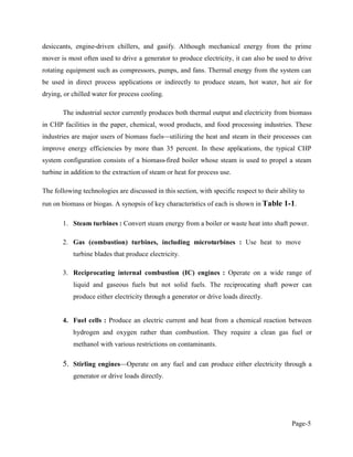
Reverend Robert Stirling
On September 27, 1816, Church of Scotland minister Robert Stirling applied for a patent for his
economizer in Edinburgh, Scotland. The device was in the form of an inverted heat engine, and
incorporated the characteristic phase shift between the displacer and piston that we see in all
Stirling Engines today[2].
The engine also featured the cyclic heating and cooling of the internal gas by means of an
external heat source, but the device was not yet known as a Stirling Engine. That name was
coined nearly one hundred years later by Dutch engineer Rolf Meijer to describe all types of
closed cycle regenerative gas engines.
Stirling originally regarded his engine as a perpetual motion machine of the second kind (i.e. all
heat supplied would be converted into work even though his original hot air engine did not
include a cooling system.
Due to the invention of the more powerful internal combustion engine at the middle of the 19th
century, the Stirling technology was abandoned. But even so, the Stirling engine had an extra
advantage over the steam engine due to its low operating cost. Also, the steam engine was prone
to major failures like explosions. The only major problem with the Stirling engine was its
tendency to fail when the cylinder being heated became too hot.](https://image.slidesharecdn.com/seminarreportonstirlingengine-170213183747/85/Seminar-report-on-stirling-engine-9-320.jpg)
![Page-3
Although improvements were made to curb up the problem, stiff competition from the internal
combustion engine forced the hot air engine out of the commercial scene.
Over the years, researchers have continued on Stirling engines, working out many of the design
solutions that are used today in low temperature differential Stirling engines.
1.3 Why design a Stirling Engine?
There are several reasons to use a Stirling Engine [3] :
1 .
cylinder there are no explosions needed to run the pistons like in an Otto or
Diesel engine. There are no ignitions, no carburetion because you only need
one kind of gas and no valve train because there are no valves. This was a big
advantage to the steam engines in the days when Stirling invented his engine
because it was much less dangerous to work next to a Sterling Engine than to a
common steam engine.
2. Inside the pistons can
have to refill it because it uses always the same body of gas.
3. To produce heat you can use whatever you want: fuel, oil, gas, nuclear power
and of course renewable energies like solar, biomass or geothermal heat.
4. The external combustion process can be designed as a continuous process, so
the most types of emissions can be reduced.
5. If heat comes from a renewable energy source they produce no emissions.
6](https://image.slidesharecdn.com/seminarreportonstirlingengine-170213183747/85/Seminar-report-on-stirling-engine-10-320.jpg)
![Page-4
used a lot in submarines. E.g. in the Royal Swedish Navy.
7. They can be constructed to run very quiet and practically without any
vibration.
8. They can run with a small temperature difference, e.g. with the heat of your
hand or from a cup of hot coffee. They can be used as little engines for work
which needs only low power.
9. They can run for a very long time because the bearings and seals can be placed
at the cool side of the engine
be checked very often ( longer period between the overhauls ).
10. They are extremely flexible. The engine can run as a CHP (combined heat and
power) because the heat which is produced to run it can easilybe collected. Or
in summers they can be used as coolers.
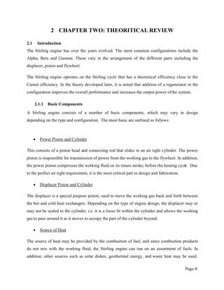
1.4 Power Generation Technologies and Stirling engine ( CHP SYSTEM ) [4] :
CHP is the sequential or simultaneous generation of multiple forms of useful energy
(usually mechanical and thermal) in a single, integrated system. CHP systems consist of a
number of individual components prime mover (heat engine), generator, heat recovery, and
electrical interconnection configured into an integrated whole.
The type of equipment that drives the overall system (i.e., the prime mover) typically
identifies the CHP system. Prime movers for CHP systems include steam turbines, gas turbines
(also called combustion turbines), spark ignition engines, diesel engines, microturbines, and fuel
cells.
These prime movers are capable of burning a variety of fuels, including biomass/biogas,
natural gas, or coal to produce shaft power or mechanical energy. Additional technologies are
also used in configuring a complete CHP system, including boilers, absorption chillers,](https://image.slidesharecdn.com/seminarreportonstirlingengine-170213183747/85/Seminar-report-on-stirling-engine-11-320.jpg)
![Page-7
1.5 Stirling engine as a prime mover [5]
in the near term at least, the Stirling engine is the best of the available options. But there are
many myths that surround this type of prime mover. One intention of this review is to inject a
measure of objectivity into the claims that are often made for Stirling engines. Another is to
consider why the time is ripe for CHP system and how, in the longer term, it could provide a
secure basis for power generation .
converts the fuel or solar energy to electrical or mechanical power, should be logical and
realisti
Achilles heel.
Stirling engines generally are small in size, ranging from 1-25 kW although some can be up to
500 kW. The Stirling engines are 15-30% efficient in converting heat energy to electricity, with
many reporting a range of 25 to 30% . The efficiency of modern Stirling generators is more than
40% .Stirling engines are expected to run 50000 hours between overhauls, and free-piston
Stirling engines may last up to 100000 hours . The cost of 1 kWh of power from a cogeneration
system is 3 4 times less than for centralized power systems, and the heat generated is essentially
free .
1.6 Scope of design
The Stirling engine we designed and fabricated was in two pieces: a normal Stirling engine that
could be heated externally using an open flame and a detachable solar concentrator that could be
placed in front of the Stirling engine to take advantage of solar heat. A gamma configuration of
the engine was chosen, whose working shall be explained further in this report.
The aim of choosing this design was to make the manufacturing cost of this engine low and keep
it simple. The design and fabrication of the engine are also documented in this report.](https://image.slidesharecdn.com/seminarreportonstirlingengine-170213183747/85/Seminar-report-on-stirling-engine-14-320.jpg)
![Page-9
Solar powered Stirling engines are becoming increasingly popular as they are a very
environmentally friendly option for power production.
Flywheel
The flywheel is connected to the output power of the power piston, and is used to store energy,
and provide momentum for smooth running of the engine. It is made of heavy material such as
steel, for optimum energy storage.
Heat Sink
The heat sink is typically the environment at ambient temperature. For small heat engines, finned
heat exchangers in the ambient air suffice as a heat sink. In the case of medium to high power
engines, a radiator may be required to transfer heat from the engine.
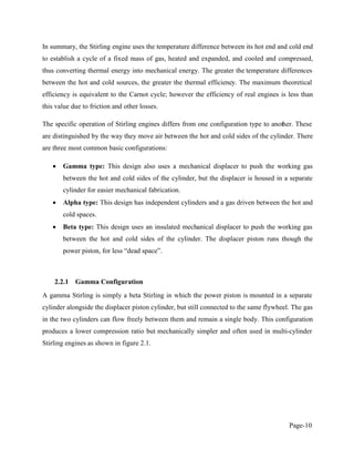
2.2 Operation and Configuration [6]
Since the Stirling engine is a closed cycle, it contains a fixed mass of gas called the "working
fluid", most commonly air, hydrogen or helium. In normal operation, the engine is sealed and no
gas enters or leaves the engine. No valves are required, unlike other types of piston engines. The
Stirling engine, like most heat engines, cycles through four main processes: cooling,
compression, heating and expansion. This is accomplished by moving the gas back and forth
between hot and cold heat exchangers, often with a regenerator between the heater and cooler.
The hot heat exchanger is in thermal contact with an external heat source, such as a fuel burner,
and the cold heat exchanger being in thermal contact with an external heat sink, such as air fins.
A change in gas temperature will cause a corresponding change in gas pressure, while the motion
of the piston causes the gas to be alternately expanded and compressed.
When the gas is heated, because it is in a sealed chamber, the pressure rises and this then acts on
the power piston to produce a power stroke. When the gas is cooled the pressure drops and this
means that less work needs to be done by the piston to compress the gas on the return stroke,
thus yielding a net power output.](https://image.slidesharecdn.com/seminarreportonstirlingengine-170213183747/85/Seminar-report-on-stirling-engine-16-320.jpg)
![Page-14
2.3 Carnot Cycle [7]
Carnot, a French Scientist showed that the most efficient possible cycle is one in which all the
heat supplied is at one fixed temperature, and all the heat rejected is rejected at a lower
temperature. The cycle therefore consists of two isothermal processes joined by two adiabatic
processes. Since all processes are reversible, then the adiabatic processes in the cycle are also
isentropic. The cycle is most conveniently represented on a T-S diagram as shown below (figure
2.4).
Figure 2.4: The Carnot cycle on a T-S diagram
(2.1)
2.4 The Stirling Cycle [8]
2.4.1 Basic Stirling cycle
The Stirling cycle comes closest to the Carnot cycle efficiency while having a higher work ratio.
Despite the fact that the efficiency may not be practical in real fabrication and testing, the
Stirling engine gives the best output.
The idealized Stirling cycle consists of four thermodynamic processes acting on the network of
the fluid; as shown blew in (figure 2.5):
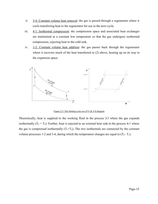
i. 2-3: Isothermal expansion: the expansion space and associated heat exchanger are
maintained at a constant high temperature and the gas undergoes isothermal
expansion absorbing heat from the heat source.](https://image.slidesharecdn.com/seminarreportonstirlingengine-170213183747/85/Seminar-report-on-stirling-engine-21-320.jpg)

This document is a seminar report submitted by Shivam Kushwah in partial fulfillment of the requirements for a Bachelor of Technology degree in Mechanical Engineering from Rajasthan Technical University, Kota. The report focuses on Stirling engines and provides an introduction to Stirling engines, a brief history, reasons for their design, and applications for power generation. It includes sections on the theoretical background of Stirling engines and discusses components, configurations, the Carnot cycle, and the Stirling cycle.


