Downloaded 409 times

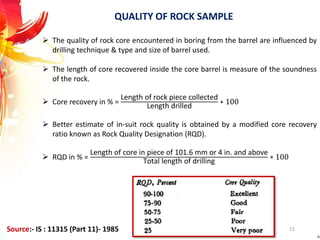
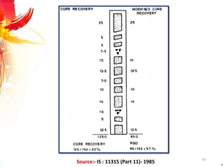
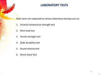

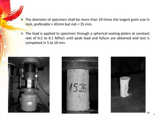
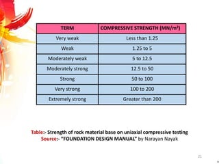
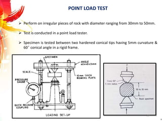
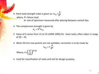


The document provides a comprehensive overview of rock drilling, sampling, and testing methods essential for geological exploration and construction purposes. It covers various techniques including test pits, percussion drilling, and rotary drilling, as well as the processes and quality assessments involved in obtaining and analyzing rock samples. Laboratory testing methods such as uniaxial compressive strength tests, point load tests, and slake durability tests are highlighted to evaluate rock properties and integrity.